JP5669552B2 - Surveillance video generator - Google Patents
Surveillance video generator Download PDFInfo
- Publication number
- JP5669552B2 JP5669552B2 JP2010278238A JP2010278238A JP5669552B2 JP 5669552 B2 JP5669552 B2 JP 5669552B2 JP 2010278238 A JP2010278238 A JP 2010278238A JP 2010278238 A JP2010278238 A JP 2010278238A JP 5669552 B2 JP5669552 B2 JP 5669552B2
- Authority
- JP
- Japan
- Prior art keywords
- video
- display
- information
- coordinates
- monitoring
- Prior art date
- Legal status (The legal status is an assumption and is not a legal conclusion. Google has not performed a legal analysis and makes no representation as to the accuracy of the status listed.)
- Expired - Fee Related
Links
Images


Landscapes
- Closed-Circuit Television Systems (AREA)
Description
本発明は、例えば広域な撮像範囲の映像に監視対象物の情報を重畳して画面上に表示させる監視映像生成装置に関するものである。 The present invention relates to a monitoring video generation apparatus that superimposes information of a monitoring target on a video in a wide imaging range and displays the information on a screen, for example.
従来の監視映像生成装置としては、例えば特許文献1のような情報表示方法が開示されている。例えば、特許文献1の情報表示方法によれば、固定された情報を表示する固定表示部を背景映像とし、可変な情報を表示する複数の可変表示部の映像を指定された順に合成して表示映像を生成している。このような情報表示方法においては、表示映像を生成する際、固定表示部の表示情報の座標に対応させて可変情報の表示情報を一定の大きさで配置し、可変表示部の映像毎に固定化してから合成している。
また、多数の情報を表示するための方法が、例えば特許文献2に開示されている。特許文献2によれば、多数の情報データをカードデータとして管理し、一定の大きさのカードデータをスタック状に表示する映像を生成することで、限られた表示領域上に重なり度合いがわかるように表示させている。また、閲覧者が表示映像上の各カードデータをマウスにより選択して移動させることで各情報データの表示位置を変更できるよう構成されている。
As a conventional monitoring video generation device, for example, an information display method as disclosed in
Further, for example, Patent Document 2 discloses a method for displaying a large amount of information. According to Patent Document 2, a large amount of information data is managed as card data, and by generating a video that displays a certain amount of card data in a stack, the degree of overlap can be seen on a limited display area. Is displayed. Further, the display position of each information data can be changed by the viewer selecting and moving each card data on the display video with a mouse.
しかしながら、特許文献1,2においては、表示領域上の各情報データを一定の大きさで表示しているため、閲覧者が着目する情報データと他の情報データとの判別を容易に行えないという課題があった。また、特許文献2においては、閲覧者がスタック状に重ねられた多数の情報データの中からマウスを用いて複数回の操作を行って着目する情報データを取り出す必要があり、操作が煩雑であるという課題があった。
However, in
この発明は、上記のような課題を解決するためになされたもので、閲覧者が少ない操作で多数の情報データの中から、着目する情報データを他の情報データと分離して判別を容易に行うことができる監視映像生成装置を提供することを目的とする。 The present invention has been made to solve the above-described problems, and enables easy discrimination by separating the focused information data from other information data from among a large number of information data with a small number of viewers. It is an object of the present invention to provide a monitoring video generation apparatus that can be performed.
この発明に係る監視映像生成装置は、旋回ズーム制御可能な撮像手段と、撮像手段の旋回ズームを制御して旋回ズーム制御値を出力する画角制御手段と、旋回ズーム制御値に対応した撮像対象物毎の位置および内容を含む対象物情報を格納するデータベースと、画角制御手段が出力した旋回ズーム制御値に対応する対象物情報をデータベースから読み出し、外部の入力装置により示される撮像範囲内の座標に基づいて、該座標を含む一定範囲内に存在する撮像対象物の対象物情報をそれぞれ重ならない座標に配置するとともに該対象物情報の表示形態を強調する情報表示制御手段と、撮像手段からの映像に情報表示制御手段からの対象物情報を重畳表示する映像出力手段とを備えたものである。 According to the present invention the monitoring image generating apparatus includes a swivel zoom controllable imaging means, and the angle control means for outputting a turning zoom control value control to the turning zooming of the imaging means, the imaging target that corresponds to turning the zoom control value reading a database for storing object information including the position and content of each object, the object information corresponding to the turning zoom control value angle control means is output from the database, the imaging range indicated by the input device of the external An information display control means for arranging the object information of the imaging object existing within a certain range including the coordinates at coordinates that do not overlap with each other, and for emphasizing the display form of the object information, and the imaging means is obtained by an image output unit that shows superimposed table object information from the information display control means to the image from.
この発明に係る監視映像生成装置によれば、上記構成により、表示映像上の指示記号の近傍に位置する監視対象物の情報データを閲覧しやすいよう動的に配置して表示することができる。その結果、閲覧者が着目する情報データを他の情報データと分離して容易に判別することができる。また、閲覧者による少ない操作で多数の情報データの中から所望の情報データを判別することができる。 According to the monitoring video generation apparatus according to the present invention, with the above configuration, it is possible to dynamically arrange and display the information data of the monitoring target located in the vicinity of the instruction symbol on the display video so as to be easily browsed. As a result, it is possible to easily determine the information data focused on by the viewer by separating it from other information data. Further, desired information data can be determined from a large number of information data with a few operations by the viewer.
以下、この発明の実施の形態を、図面を参照しながら詳細に説明する。
実施の形態1.
図1は、実施の形態1に係る監視映像生成装置を含む映像監視表示システムの構成を示している。
映像監視表示システム1は、図1に示すように、監視映像生成装置10、表示装置80、操作入力装置90で構成されている。
Hereinafter, embodiments of the present invention will be described in detail with reference to the drawings.
FIG. 1 shows a configuration of a video surveillance display system including a surveillance video generation device according to the first embodiment.
As shown in FIG. 1, the video
表示装置80は、後述する監視映像生成装置10で生成された監視映像を表示するものであり、例えばディスプレイで構成される。
The
操作入力装置90は、閲覧者(外部)による操作により、表示装置80の監視映像上に重畳表示された指示記号を操作させる操作信号を監視映像生成装置10へ出力するものであり、例えば監視映像上の指示記号としてのマウスカーソルを操作するマウスやキーボードで構成される。
The
監視映像生成装置10は、図1に示すように、カメラ11、映像入力手段12、画角制御手段13、データベース14、情報表示制御手段15、映像出力手段16で構成されている。
カメラ11は、既知の技術を用いて横方向に旋回するパン動作、縦方向に旋回するチルト動作、ズーム制御可能であり、撮像可能な全範囲からパン・チルト・ズーム動作(旋回・ズーム動作)による画角に応じた範囲(撮像範囲)内の監視対象物を撮像する。カメラ11は、撮像した映像の信号を垂直または水平同期信号とともに監視映像生成装置10へ出力するよう構成されている。
As shown in FIG. 1, the monitoring
The
映像入力手段12は、カメラ11で撮像された映像を、垂直/水平同期信号を含むアナログの映像信号で入力し、垂直/水平同期信号に基づき映像信号を映像フレーム毎にA/D(アナログ/デジタル)変換するよう構成されている。
映像入力手段12は、フレーム毎にデジタル化した映像信号の輝度値と色信号値からRGB信号を得て、内蔵のメモリ(図示せず)に格納するとともに映像出力手段16に出力する。
The video input means 12 inputs the video imaged by the
The video input means 12 obtains an RGB signal from the luminance value and color signal value of the video signal digitized for each frame, stores it in a built-in memory (not shown), and outputs it to the video output means 16.
画角制御手段13は、閲覧者から図示しないグラフィカルユーザインタフェースの操作により与えられた指示Aにしたがってカメラ11のパン・チルト・ズーム(旋回・ズーム)を制御する。画角制御手段13は、情報表示制御手段15からの要求に応じてカメラ11の制御値としてのパン・チルト・ズーム値(以下、PTZ値)を出力する。
The angle-of-view control means 13 controls pan / tilt / zoom (turn / zoom) of the
データベース14は、予め監視対象物毎に、カメラ11のPTZ値に対応して表示する情報データ14aを格納している。情報データ14aは、カメラ11が撮像可能な全範囲内の監視対象物毎に対応する情報であり、例えば各監視対象物を識別するための名称情報、監視対象物毎の異常発生を示すアラーム情報、監視対象物毎の状態を示す状態情報が該当する。情報データ14aには付属情報として、カメラ11が撮像可能な全撮像範囲(全方位座標空間)に対する監視対象物の相対座標(登録座標)を示す位置情報と、情報データ14aの表示サイズ、形状、色等の表示形態を示す表示属性情報が付加されている。
データベース14は、要求に応じて情報データ14aを情報表示制御手段15へ出力する。
The
The
情報表示制御手段15は、閲覧者からの操作入力に基づいて該閲覧者に提示する情報データと付属データをデータベースから読み出し、閲覧者が外部の操作入力装置90から指定した座標に基づき、閲覧者が指定した座標近傍の情報データの表示形態を動的に変更するとともに、該情報データが重ならないよう表示座標を配置して出力するよう機能する。
具体的には、情報表示制御手段15は、画角制御手段13から入力したPTZ値に基づきカメラ11の撮像範囲を算出し、データベース14の情報データ14aに含まれる位置情報を参照して撮像範囲内に含まれる監視対象物に対応する情報データ14aをデータベース14から取得する。情報表示制御手段15は、情報データ14aに含まれる位置情報とカメラ11の撮像範囲に基づき、監視映像表示領域としてのカメラ11の撮像範囲における情報データ14aの表示座標を算出し、情報データ14aに表示座標を付加して映像出力手段16へ出力して監視映像の表示を指示する。
また、情報表示制御手段15は、操作入力装置90から後述する映像出力手段16を介して、監視映像上に重畳表示された指示記号としてのマウスカーソルの座標(指示記号座標)を取得し、このマウスカーソル座標と情報データ14aの表示座標に基づきマウスカーソルの近傍領域(指示記号近傍領域)に表示される情報データ14aを抽出する。情報表示制御手段15は、抽出した情報データ14aに含まれる表示属性情報に対し、強調表示情報としての強調フラグをオンにするとともに強調表示形態を示す情報を付加して更新する。
さらに、情報表示制御手段15は、抽出した情報データ14aの表示座標に基づき、後述する再配置処理を行い情報データ14a同士が重ならないよう座標をずらして表示座標を更新する。
The information display control means 15 reads information data and attached data presented to the viewer based on the operation input from the viewer from the database, and based on the coordinates designated by the viewer from the external
Specifically, the information display control unit 15 calculates the imaging range of the
Further, the information display control means 15 acquires the coordinates of the mouse cursor (instruction symbol coordinates) as an instruction symbol superimposed on the monitoring video from the
Further, the information display control means 15 performs a rearrangement process described later based on the display coordinates of the extracted
映像出力手段16は、カメラ11からの映像に情報表示制御手段15からの情報データと付属データを重畳表示するとともに、閲覧者が指定した座標近傍の情報データを動的に配置して重畳表示するよう機能する。
具体的には、映像出力手段16は、情報表示制御手段15から表示座標と表示属性情報を含む情報データ14aを入力し、情報データ14aを表示属性情報に沿った表示形態に加工処理する。このとき、映像出力手段16は、例えば、情報データ14aを太字で表示する処理や情報データ14aの表示色を変える処理を行う。
また、映像出力手段16は、映像入力手段12から映像(映像信号)を入力し、情報データ14aの表示座標を用いて、加工処理後の情報データ14aを映像表示領域の座標位置に重畳配置する。このとき、映像出力手段16は、強調フラグがオンになっている情報データ14aに対し、情報データ14a同士が重ならないよう各座標を変更して閲覧者が見易くなるよう動的に配置する処理を行う。
さらに、映像出力手段16は、操作入力装置90から監視映像上の指示記号を操作させる操作信号を入力し、操作信号に基づき、監視映像上の指示記号としてのマウスカーソルを生成して監視映像に重畳する。映像出力手段16は、生成した監視映像を表示装置80へ出力して表示させる。
The video output means 16 superimposes the information data from the information display control means 15 and the attached data on the video from the
Specifically, the
The video output means 16 receives the video (video signal) from the video input means 12, and uses the display coordinates of the
Further, the video output means 16 receives an operation signal for operating an instruction symbol on the monitoring video from the
次に、図2から図12を用いて監視映像生成装置10における処理動作について説明する。図2は、映像入力手段12の処理を示している。
映像入力手段12は、カメラ11から映像信号、垂直/水平同期信号を入力すると処理を開始(スタート)し、垂直/水平同期信号に基づき、映像信号を既知の技術を用いてA/D変換してデジタル化する(ステップST100)。このとき、デジタル化した映像信号には輝度値と色信号値が含まれる。
映像入力手段12は、映像信号の輝度値と色信号値を用いてRGB信号を得て(ステップST101)、映像信号としてのRGB信号を図示しないメモリに格納するとともに映像出力手段16へ出力する(ステップST102)。
映像入力手段12は、次の垂直同期信号が入力されるのを待機するとともに(ステップST103)、カメラ11からの映像信号の入力が終了したかどうかを判定し(ステップST104)、ステップST104において映像信号の入力が終了していないと判定した場合(ステップST104“NO”)、ステップST100からの処理を繰り返す。
一方、映像入力手段12は、ステップST104において映像信号の入力が終了したと判定すると(ステップST104“YES”)、処理を終了する(エンド)。
Next, the processing operation in the monitoring
The video input means 12 starts (starts) processing when a video signal and a vertical / horizontal synchronization signal are input from the
The video input means 12 obtains an RGB signal using the luminance value and the color signal value of the video signal (step ST101), stores the RGB signal as the video signal in a memory (not shown) and outputs it to the video output means 16 ( Step ST102).
The video input means 12 waits for the next vertical synchronization signal to be input (step ST103), determines whether or not the input of the video signal from the
On the other hand, if the video input means 12 determines in step ST104 that the input of the video signal has ended (step ST104 “YES”), the video input means 12 ends the processing (end).
図3は、画角制御手段13におけるカメラ11のパン・チルト・ズーム動作の制御(旋回・ズーム制御)処理を示している。
画角制御手段13は、外部から指示が与えられると処理を開始する(スタート)。画角制御手段13は、与えられた指示に含まれるPTZ値を取得すると(ステップST110)、カメラ11へPTZ値を出力する(ステップST111)。
カメラ11では、画角制御手段13からPTZ値が与えられると、PTZ値にしたがって図示しないモータによりパン・チルト・ズームを変化させる。
FIG. 3 shows control (turning / zoom control) processing of the pan / tilt / zoom operation of the
The angle-of-view control means 13 starts processing when an instruction is given from the outside (start). When the angle-of-view control means 13 acquires the PTZ value included in the given instruction (step ST110), it outputs the PTZ value to the camera 11 (step ST111).
In the
図4は、画角制御手段13においてカメラ11から旋回・ズーム値を取得する処理を示している。
画角制御手段13は、情報表示制御手段15から要求を受けると処理を開始し(スタート)、カメラ11へPTZ値(旋回・ズーム値)を問い合わせる信号を送信する(ステップST120)。画角制御手段13は、カメラ11から問い合わせ信号に応じた応答信号を受信しPTZ値を取得すると(ステップST121)、PTZ値を図示しないメモリに格納する(ステップST122)。画角制御手段13は、メモリに格納したPTZ値を情報表示制御手段15へ出力し、旋回・ズーム値を取得する処理を終了する(エンド)。
FIG. 4 shows processing for obtaining the turning / zoom value from the
Upon receiving a request from the information display control means 15, the angle-of-view control means 13 starts processing (start) and transmits a signal for inquiring about the PTZ value (turning / zoom value) to the camera 11 (step ST120). When the angle-of-view control means 13 receives a response signal corresponding to the inquiry signal from the
図5は、監視映像生成装置10における強調表示処理前の監視映像を示している。
監視映像として表示された映像表示領域100には、監視対象物の映像101として、例えば川、橋、山、ビルが表示されている。映像表示領域100には、各監視対象物の映像101に対応する情報データの映像102と、各監視対象物の映像101を指し示す矢印103が重畳されている。この表示状態の監視映像は、図5に示すように、各監視対象物の情報データが周囲の情報データと重なって表示され、閲覧者が読み取れない情報データが存在している。
FIG. 5 shows a monitoring video before highlighting processing in the monitoring
In the
図6は、監視映像生成装置10における強調表示処理を説明するための監視映像(a)、(b)を示している。
監視映像(a)は、図5の映像表示領域100上にマウスカーソル(指示記号)104が重畳された映像である。マウスカーソル104は、閲覧者(外部)から操作入力装置90を介して入力した操作信号に基づき映像表示領域100上を指し示すものであり、例えば監視映像上に表示されるマウスカーソルである。ここで、マウスカーソル104が監視映像(a)の位置から監視映像(b)の位置に移動すると、マウスカーソル104の座標から所定範囲内(マウスカーソル座標近傍領域105)に表示されている監視対象物の情報データに対して後述する強調表示処理を行う。
FIG. 6 shows monitoring videos (a) and (b) for explaining the highlight display processing in the monitoring
The monitoring video (a) is a video in which a mouse cursor (instruction symbol) 104 is superimposed on the
監視映像(b)は、図6に示すように、マウスカーソル104を監視対象物の位置に移動した場合の表示例を示しており、監視映像上におけるマウスカーソル104の座標から所定範囲内(マウスカーソル座標近傍領域105)に表示される監視対象物(ビル115、ビル118、ビル119、ビル120)の情報データ107が、それぞれ太枠で囲まれ、マウスカーソル座標近傍領域105外に表示される監視対象物の情報データ106に対し最前面に表示されるとともに、それぞれの位置が重ならないよう再配置される。
As shown in FIG. 6, the monitoring video (b) shows a display example when the
図7は、監視映像生成装置10が撮像可能な全方位座標空間における現在の撮像範囲の位置を示している。
全方位座標空間110は、カメラ11で撮像可能な全範囲を示しており、カメラ11においてPTZ値に対応する画角で撮像された現在の撮像範囲111を含んでいる。この全方位座標空間110においては、チルト値原点(T0)112、チルト値最大値(Tmax)113、パン値原点(P0)114、パン値最大値(Pmax)115、全方位座標空間110の高さ(Height)116、全方位座標空間110の幅(Width)117、チルト値原点112およびパン値原点114に対する現在の撮像範囲111の座標としてのPTZ値(Pn,Tn)118、撮像範囲111の幅(Wn)119、撮像範囲111の高さ(Hn)120が定義付けられており、これらの値を用いて後述する強調表示処理を行う。
FIG. 7 shows the position of the current imaging range in the omnidirectional coordinate space that can be imaged by the monitoring
The omnidirectional coordinate
図8は、監視映像生成装置10における情報表示制御手段15の処理を示している。
情報表示制御手段15は、所定の周期で画角制御手段13に対してPTZ値(旋回・ズーム値)を要求して処理を開始し(スタート)、カメラ11から画角制御手段13を介して要求に応じたPTZ値を受信する(ステップST130)。
情報表示制御手段15は、PTZ値に基づき全監視対象範囲におけるカメラ11の現在の撮像範囲を算出し、データベース14内を参照して現在の撮像範囲内に含まれる情報データ14aを抽出する(ステップST131)。このとき、情報表示制御手段15は、上述した図7に示すチルト値最大値(Tmax)113、パン値最大値(Pmax)115、全方位座標空間110の高さ(Height)116、全方位座標空間110の幅(Width)117、現在のPTZ値(Pn,Tn)118、撮像範囲111の幅(Wn)119、撮像範囲111の高さ(Hn)120に基づき、次の(式1)により全方位座標空間110におけるカメラ11の撮像範囲111の座標値(x,y)を算出する。なお、(式1)において、(Width)と(Height)の値は、PTZ値のズーム値に対応する値を用いる。
x=Pn/Pmax・Width
y=Tn/Tmax・Height ・・・(式1)
情報表示制御手段15は、抽出した情報データ14aをデータベース14から取得し、カメラ11の撮像範囲111と情報データ14aの位置情報に基づき映像表示領域100における情報データ14aの表示座標を算出するとともに、情報データ14aの表示属性情報を用いて情報データ14aの表示属性を設定する(ステップST132)。
情報表示制御手段15は、情報データ14aに表示座標と表示属性を付加して映像出力手段16へ出力し、監視映像の表示を指示する(ステップST133)。
FIG. 8 shows processing of the information display control means 15 in the monitoring
The information display control means 15 requests the PTZ value (turning / zoom value) from the angle-of-view control means 13 at a predetermined cycle to start processing (start), and from the
The information display control means 15 calculates the current imaging range of the
x = Pn / Pmax · Width
y = Tn / Tmax · Height (Expression 1)
The information display control means 15 acquires the extracted
The information display control means 15 adds display coordinates and display attributes to the
情報表示制御手段15は、操作入力装置90から映像出力手段16を介してマウスカーソル座標(指示記号座標)を入力すると、マウスカーソル座標が映像表示領域100内にあるかを判定する(ステップST134)。判定方法は、例えば、以下の(式2)を満たす場合にマウスカーソル座標が映像表示領域100内にあると判定する。
ここで、情報表示制御手段15が入力するマウスカーソル座標は、図5,6に示す映像表示領域100における相対座標(x、y)である。また、(式2)のSwは映像表示領域100における幅を示し、Shは映像表示領域100における高さを示している。
x≧0 かつ x < Sw かつ y≧0 かつ y < Sh ・・・(式2)
When the mouse cursor coordinates (instruction symbol coordinates) are input from the
Here, the mouse cursor coordinates input by the information display control means 15 are relative coordinates (x, y) in the
x ≧ 0 and x <Sw and y ≧ 0 and y <Sh (Expression 2)
情報表示制御手段15は、ステップST134において、マウスカーソルが映像表示領域100内に存在しないと判定すると(ステップST134“NO”)、処理を終了する(エンド)。
一方、情報表示制御手段15は、ステップST134において、マウスカーソルが映像表示領域100内に存在すると判定すると(ステップST134“YES”)、マウスカーソル座標とPTZ値と情報データ14aの位置情報に基づき、後述する抽出処理を行って、マウスカーソルの座標から所定範囲(指示座標近傍領域105)内に表示された情報データ107を抽出し、その情報データ107の表示属性情報に含まれる強調フラグ(強調表示情報)をオンにする(ステップST135)。ここで、マウスカーソルの座標の所定範囲より外側に表示された監視対象物の情報データ106の強調フラグはオフに設定される。
If the information display control means 15 determines in step ST134 that the mouse cursor does not exist in the video display area 100 (step ST134 "NO"), the information display control means 15 ends the processing (END).
On the other hand, if the information display control means 15 determines in step ST134 that the mouse cursor exists in the video display area 100 (step ST134 "YES"), based on the mouse cursor coordinates, the PTZ value, and the position information of the
情報表示制御手段15は、後述する再配置処理を行い、強調フラグをオンにした情報データ107の映像を再配置するための座標を算出し、表示座標を置き換えて更新する(ステップST136)とともに、強調表示形態を示す情報を表示属性情報に書き込んで更新し、情報データの表示属性の設定を行う(ステップST137)。情報表示制御手段15は、更新した表示座標と表示属性情報を含む情報データ14aを映像出力手段16へ出力し、監視映像の表示を指示する(ステップST138)。情報表示制御手段15は、ステップST138において監視映像の表示を指示すると処理を終了する(エンド)。
The information display control means 15 performs rearrangement processing to be described later, calculates coordinates for rearranging the video of the
ここで、ステップST135におけるマウスカーソル座標近傍領域105内の監視対象物に対応する情報データ107を抽出する方法の詳細について図9を用いて説明する。
情報表示制御手段15は、マウスカーソル座標を入力すると抽出処理を開始し(スタート)、画角制御手段13にPTZ値を要求する信号を出力して画角制御手段13からPTZ値を取得する。
情報表示制御手段15は、マウスカーソル座標とPTZ値に基づきマウスカーソル座標を変換して、全方位座標空間110内におけるマウスカーソル座標を取得する(ステップST140)。
Here, details of the method of extracting the
When the mouse cursor coordinates are input, the information display control unit 15 starts extraction processing (start), outputs a signal requesting the PTZ value to the view
The information display control means 15 converts the mouse cursor coordinates based on the mouse cursor coordinates and the PTZ value, and acquires the mouse cursor coordinates in the omnidirectional coordinate space 110 (step ST140).
情報表示制御手段15は、データベース14を参照して各情報データ14aの位置情報に示された登録座標を取得し(ステップST141)、全方位座標空間110内におけるマウスカーソル座標からの所定範囲(マウスカーソル座標近傍領域105)に各情報データ14aの位置情報としての登録座標が含まれているかどうか重なり判定を行う(ステップST142、ステップST143)。重なり判定は、例えば、次の(式3)を満たす場合、重なると判定するものとする。
![]()
![]()
情報表示制御手段15は、マウスカーソル座標近傍領域105に情報データ14aの登録座標が含まれていないと判定した場合(ステップST143“NO”)、抽出処理を終了(エンド)してステップST136へ進む。
一方、情報表示制御手段15は、マウスカーソル座標近傍領域105に情報データ14aのが含まれていると判定した場合(ステップST143“YES”)、その情報データ14aの登録座標を映像表示領域100の座標に変換して出力し(ステップST144)、抽出処理を終了(エンド)してステップST136へ進む。
If the information display control means 15 determines that the registered coordinates of the
On the other hand, when the information display control means 15 determines that the
ここで、ステップST136における情報データの再配置処理の詳細について図10、図11を用いて説明する。ここで再配置処理の説明においては、マウスカーソル座標近傍領域105内の監視対象物に対応する情報データを、単に「情報データ」と記載して説明する。
情報表示制御手段15は、上述したステップST135の抽出処理を終了すると、各情報データの表示座標を用いて、各情報データ相互の距離を算出する(ステップST150)。情報表示制御手段15は、図11(a)に示すように4つの情報データ200,202,204,206に対して再配置処理を行う場合、各情報データ200,202,204,206の表示座標201,203,205,207を用いて、図11(b)に示す各表示座標間の距離210,211,212,213,214,215を求める。このとき、例えば、ユークリッド距離による距離算出方法を用いて距離を算出する。
情報表示制御手段15は、各表示座標間の距離210,211,212,213,214,215に基づき、次の(式4)を用いて情報データ相互間のクーロン力を算出する(ステップST151)。
F=k/L ・・・(式4)
(式4)においては、クーロン力F、定数k、各表示座標間の距離Lを示している。
Details of the information data rearrangement process in step ST136 will be described with reference to FIGS. Here, in the description of the rearrangement process, the information data corresponding to the monitoring object in the mouse cursor coordinate
When the information display control means 15 ends the extraction process of step ST135 described above, the information display control means 15 calculates the distance between the information data using the display coordinates of the information data (step ST150). When the information display control means 15 performs the rearrangement process on the four pieces of
Based on the
F = k / L (Formula 4)
In (Formula 4), the Coulomb force F, the constant k, and the distance L between each display coordinate are shown.
情報表示制御手段15は、クーロン力Fを情報データ間の距離を遠ざける斥力として働くよう用いて、表示座標201,203,205,207のずらし量を算出する(ステップST152)。このとき、情報表示制御手段15は、例えば図11(c)に示すように、情報データ202と情報データ206間の距離213の延長線上にクーロン力Fの大きさでベクトル220,223を定め、このベクトル220,223をずらし量とする。
The information display control means 15 calculates the shift amount of the display coordinates 201, 203, 205, 207 using the Coulomb force F as a repulsive force that increases the distance between the information data (step ST152). At this time, for example, as shown in FIG. 11C, the information display control means 15 determines
情報表示制御手段15は、ずらし量を用いて表示座標をずらし、各情報データ200,202,204,206の表示座標201,203,205,207を更新する(ステップST153)。このとき、情報表示制御手段15は、例えば図11(c)に示すように、表示座標203をベクトル220ずらし表示座標222に更新し、表示座標207をベクトル223ずらし表示座標225に更新する。
このように再配置処理により更新された表示座標222,225を用いて後述する映像出力処理を行うことにより、情報データ202が情報データ221の位置に表示され、情報データ206が情報データ224の位置に表示されるので、情報データを動的に配置することができる。
The information display control unit 15 shifts the display coordinates using the shift amount, and updates the display coordinates 201, 203, 205, and 207 of the
By performing the video output processing described later using the display coordinates 222 and 225 updated by the rearrangement processing as described above, the
情報表示制御手段15は、表示座標を更新すると、更新した表示座標を用いて情報データの表示領域間の重なりを判定する(ステップST154)。このとき、情報表示制御手段15は、例えば2つの情報データの表示領域における右上端の座標を示す始点座標(iX,iY)と(iXr,iYb)、左下端の座標を示す終点座標(jX,jY)と(jXr,jYb)を用いて、次の(式5)を満たす場合、重なり有りと判定する。
iX < jXr かつ
jY < iYb かつ
iXr < jX かつ
jYb < iY ・・・(式5)
情報表示制御手段15は、重なり有りと判定した場合(ステップST154“YES”)、ステップST150からの処理を繰り返す。
一方、情報表示制御手段15は、重なりが無いと判定した場合(ステップST154“NO”)、情報データの再配置処理を終了し(エンド)、上述のステップST137の処理へ進む。
When the display coordinates are updated, the information display control means 15 determines the overlap between the display areas of the information data using the updated display coordinates (step ST154). At this time, the information display control means 15, for example, the start point coordinates (iX, iY) and (iXr, iYb) indicating the coordinates of the upper right end in the display area of the two information data, and the end point coordinates (jX, jY) and (jXr, jYb) are used, and if the following (Expression 5) is satisfied, it is determined that there is an overlap.
iX <jXr and jY <iYb and iXr <jX and jYb <iY (Formula 5)
If it is determined that there is an overlap (step ST154 “YES”), the information display control means 15 repeats the processing from step ST150.
On the other hand, when it is determined that there is no overlap (step ST154 “NO”), the information display control means 15 ends the information data rearrangement process (end), and proceeds to the process of step ST137 described above.
図12は、映像出力手段16の処理を示している。映像出力手段16は、図12に示すように、カメラ11で撮像された映像を映像入力手段12を介して入力することで処理を開始する(スタート、ステップST160)。
映像出力手段16は、情報表示制御手段15から情報データ、表示属性情報、表示座標を入力すると、カメラ11で撮像された映像を背景として、情報データを表示属性情報に沿った表示形態に加工処理し、表示座標で指定された映像表示領域の座標に重畳して監視映像を描画する(ステップST161)。このとき、映像出力手段16は、例えば、上述した図5,6に示すように、表示属性情報に基づいて矩形を描画し、矩形内に情報データの内容を文字列として描画するとともに、矩形から表示座標の間を結ぶ矢印を描画する。また、強調フラグがオンにされた情報データは、表示属性情報に付加された表示形態で強調表示される。このとき、映像出力手段16は、例えば、情報データを示す文字列を囲む矩形の大きさを変更したり強調色で描画し、最前面で表示する監視映像を表示装置80へ出力する(ステップST162、エンド)。
FIG. 12 shows the processing of the video output means 16. As shown in FIG. 12, the
When the information data, display attribute information, and display coordinates are input from the information display control unit 15, the
以上のように、実施の形態1の監視映像生成装置10は、旋回・ズーム制御可能なカメラ11と、カメラ11の旋回・ズームを制御して該旋回・ズーム値を出力する画角制御手段13と、旋回・ズーム値に対応して表示する情報データを格納するデータベース14と、画角制御手段13から入力した旋回・ズーム値に対応する情報データ14aをデータベース14から読み出し、閲覧者が外部の操作入力装置90から指定した座標に基づき、閲覧者が指定した座標近傍の情報データの表示形態を動的に変更するとともに、該情報データが重ならないよう表示座標を配置して出力する情報表示制御手段15と、カメラ11からの映像に情報表示制御手段15から入力した情報データを重畳表示し、閲覧者が指定した座標近傍の情報データを動的に配置する映像出力手段16とを備えたことにより、閲覧者による操作入力装置90からのマウスカーソルの操作に応じて、画面上のマウスカーソルの近傍に表示された監視対象物の情報データを動的に強調するよう変更して表示し、監視対象物の情報データを閲覧しやすいよう動的に配置して表示することができる。その結果、閲覧者が着目する情報データを他の情報データと分離して容易に判別することができる。また、閲覧者が少ない操作で多数の情報データの中から所望の情報データを判別することができる。
As described above, the monitoring
実施の形態2.
上記実施の形態1においては、情報データ内容としての文字列を重畳した監視映像を表示する構成を説明した。実施の形態2は、図形を重畳した監視映像を表示する構成について説明する。なお、実施の形態2の監視映像生成装置10は、実施の形態1における情報データ14aに含まれる表示属性情報と映像出力手段16における処理が異なるので、図示を省略して説明するとともに、映像出力手段16以外の説明を省略する。
Embodiment 2. FIG.
In the first embodiment, the configuration for displaying the monitoring video on which the character string as the information data content is superimposed has been described. In the second embodiment, a configuration for displaying a monitoring video on which a figure is superimposed will be described. The monitoring
実施の形態2における情報データ14aに付加した表示属性情報は、監視対象物に対応した図形を示す図形情報を含んでおり、図形情報は例えば3Dグラフィクス、映像、アイコンを示す情報である。
映像出力手段16は、情報表示制御手段15から情報データ14aを入力すると、情報データ14aに付加された表示属性情報に含まれる図形情報に基づき図形を描画し、表示座標に基づき図形を映像表示領域上の座標に重畳し、監視映像を生成する。
The display attribute information added to the
When the
次に実施の形態2の監視映像生成装置10における特徴的な処理について説明する。
実施の形態2の情報表示制御手段15は、実施の形態1の情報データ14aに付加された表示属性情報に換えて図形情報を含む表示属性情報を取得する以外の処理が実施の形態1の図8の処理と同様であるため、情報表示制御手段15の処理の説明を省略する。
Next, characteristic processing in the monitoring
The information display control unit 15 according to the second embodiment performs processing other than obtaining display attribute information including graphic information instead of the display attribute information added to the
実施の形態2の映像出力手段16は、実施の形態1の図12におけるステップST161以外の処理が同様であるため、ステップST161以外の処理の説明を省略する。
映像出力手段16は、情報表示制御手段15から情報データ、図形情報を含む表示属性情報、表示座標を入力すると、カメラ11で撮像された映像を背景として、情報データを表示属性情報に沿った表示形態に加工処理し、表示座標で指定された映像表示領域の座標に重畳して監視映像を描画する(ステップST161)。このとき、映像出力手段16は、例えば、表示属性情報に基づいて矩形を描画するとともに図形情報に基づき図形を描画する。また、映像出力手段16は、矩形内に情報データの内容を文字列として描画するとともに矩形から表示座標の間を結ぶ矢印を描画する。
Since the video output means 16 of the second embodiment is the same as the process other than step ST161 in FIG. 12 of the first embodiment, the description of the processes other than step ST161 is omitted.
When the information output control unit 15 receives information data, display attribute information including graphic information, and display coordinates, the
以上のように、実施の形態2の監視映像生成装置10は、実施の形態1の効果に加え、情報データの表示内容として図形を映像出力手段に出力する映像出力手段16を備えたことにより、監視対象物に対応する図形を表示する監視映像を生成することができる。その結果、閲覧者が監視映像における図形により、情報データをより視覚的に容易に判別することができるという効果を奏する。
As described above, in addition to the effects of the first embodiment, the monitoring
実施の形態3.
上記実施の形態1においては、カメラ11の撮像画角を外部の図示しないグラフィカルユーザインタフェースを用いて操作する構成について説明した。実施の形態3は、閲覧者が操作入力装置を操作することによりカメラの旋回・ズーム動作を制御する構成について説明する。
In the first embodiment, the configuration in which the imaging angle of view of the
図13は、実施の形態3に係る監視映像生成装置を含む映像監視表示システムの構成を示している。
映像監視表示システム3は、図13に示すように、監視映像生成装置30、カメラ11、表示装置80、操作入力装置93で構成されており、監視映像生成装置30と操作入力装置93以外の構成は実施の形態1と同様であるため、監視映像生成装置30と操作入力装置93以外の構成は図1と同一の符号を付しての説明を省略する。
FIG. 13 shows a configuration of a video surveillance display system including the surveillance video generation device according to the third embodiment.
As shown in FIG. 13, the video
操作入力装置93は、閲覧者(外部)による操作により、表示装置80の監視映像上に重畳表示された指示記号を操作させる操作信号を監視映像生成装置30へ出力する。また、操作入力装置93は、カメラ11の旋回・ズームを操作させる操作信号を監視映像生成装置30へ出力する。
The
監視映像生成装置30は、図13に示すように、カメラ11、映像入力手段12、画角制御手段33、データベース14、情報表示制御手段15、映像出力手段36で構成されており、画角制御手段33と映像出力手段36以外の構成が実施の形態1と同様であるため、図1と同一の符号を付して説明を省略する。
As shown in FIG. 13, the monitoring
映像出力手段36は、実施の形態1の映像出力手段16の構成に加え、操作入力装置93からカメラ11の撮像画角を操作させる操作信号を入力すると、監視映像上の指示記号の座標と操作信号に基づくPTZ値を示す制御信号を画角制御手段33へ出力する。
In addition to the configuration of the
画角制御手段33は、映像出力手段36から制御信号を入力すると、制御信号にしたがって、カメラ11にPTZ値を与えることによりカメラ11の旋回・ズーム動作を制御するよう機能する。
When the control signal is input from the video output means 36, the angle-of-view control means 33 functions to control the turning / zooming operation of the
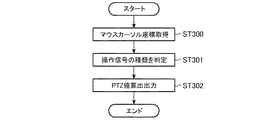
次に図14を用いて、実施の形態3の監視映像生成装置30における特徴的な処理を説明する。
監視映像生成装置30は、操作入力装置93からカメラ11の撮像画角を操作させる操作信号を入力すると、処理を開始する(スタート)。このとき、操作入力装置93から操作される指示記号がマウスである場合、例えば、マウス左ボタンクリックにおいてはカメラ11をズーム動作(拡大)して撮像するよう操作され、マウス右クリックにおいてはズーム動作縮小を行うようにする。映像出力手段36は、操作入力装置93からの操作信号に基づき、監視映像上のマウスカーソル(指示記号)の座標を求め、マウスカーソルの座標と操作信号を画角制御手段33へ出力する。
Next, characteristic processing in the monitoring
The monitoring
画角制御手段33は、映像出力手段36からマウスカーソルの座標を取得する(ステップST300)とともに、操作信号を入力し操作信号が示す画角制御の種類を判定する(ステップST301)。画角制御手段33は、マウスカーソルの座標と操作信号が示す画角制御の種類に基づきPTZ値を算出してカメラ11へ出力する(ステップST302)。カメラ11では、PTZ値を入力すると、PTZ値にしたがってカメラ11の旋回・ズームを変更して処理を終了する(エンド)。
The angle-of-view control means 33 acquires the coordinates of the mouse cursor from the video output means 36 (step ST300), inputs an operation signal, and determines the type of angle-of-view control indicated by the operation signal (step ST301). The angle of view control means 33 calculates a PTZ value based on the coordinates of the mouse cursor and the type of angle of view control indicated by the operation signal, and outputs it to the camera 11 (step ST302). In the
以上のように、実施の形態3の監視映像生成装置30は、実施の形態1の効果に加え、外部から操作入力装置93を介して操作された監視映像上のマウスカーソルの座標と、その操作内容を示す操作信号に基づき、情報データ上を外部の操作入力装置93から指示された場合、画角制御手段33に対して旋回・ズーム制御を指示する映像出力手段36を備えるよう構成したことにより、監視者が監視映像上の監視対象物、情報データを指して撮像画角を変更させるよう操作することができるので、閲覧者が注目する情報を精査することができるという効果が得られる。
As described above, in addition to the effect of the first embodiment, the monitoring
実施の形態4.
上記実施の形態1〜3において、カメラ11から入力した映像を直接用いて監視映像を生成する構成について説明したが、この構成では、カメラ11の故障等の原因により映像入力が中断した場合、監視映像を生成できない。そこで、実施の形態4は、カメラ11からの映像入力が中断した場合にも監視映像を生成できる構成について説明する。
In the first to third embodiments, the configuration in which the video input from the
図15は、実施の形態4に係る監視映像生成装置を含む映像監視表示システムの構成を示している。図15において、映像監視表示システム4の構成は、監視映像生成装置40以外の構成は実施の形態1と同様であるため、図1と同一の符号を付して説明を省略する。
FIG. 15 shows a configuration of a video surveillance display system including the surveillance video generation device according to the fourth embodiment. In FIG. 15, the configuration of the video
監視映像生成装置40は、図15に示すように、映像入力手段12、画角制御手段43、データベース14、情報表示制御手段15、映像出力手段46、記録手段49で構成されている。ここで、映像入力手段12、データベース14、情報表示制御手段15の構成については実施の形態1と同様であるため図1と同一の符号を付して説明を省略する。
As shown in FIG. 15, the monitoring
画角制御手段43は、実施の形態1の画角制御手段13または実施の形態3の画角制御手段33で示した構成に加え、カメラ11の旋回・ズーム値としてのPTZ値を監視しており、PTZ値を映像出力手段46へ出力する。
The view angle control means 43 monitors the PTZ value as the turning / zoom value of the
映像出力手段46は、実施の形態1の映像出力手段16で示した構成に加え、映像入力手段12を介してカメラ11からの映像を入力したかどうかを判定し、映像出力手段46は、カメラ11から映像入力があると判定した場合、入力した映像を記録手段49へ出力して記憶させる。一方、カメラ11からの映像入力が無いと判定した場合、画角制御手段43から入力した現在のPTZ値に基づき記録手段49に保存されたPTZ値を参照して現在のPTZ値に対応するPTZ値で撮像された映像を取得する。
The video output means 46 determines whether or not the video from the
記録手段49は、映像出力手段46から映像とともに映像撮像時のPTZ値(撮像画角値)を取得し、映像と映像撮像時のPTZ値を対応付けて記憶する。 The recording means 49 acquires the PTZ value (imaging angle of view value) at the time of image capturing together with the image from the image output means 46, and stores the image and the PTZ value at the time of image capturing in association with each other.
次に、図16を用いて、監視映像生成装置40における特徴的な処理を説明する。
監視映像生成装置40の映像出力手段46は、映像入力手段12からの映像入力の有無を判定しており(ステップST400)、映像入力手段12からの映像入力があると判定すると(ステップST400“YES”)、映像入力手段12から映像を入力して通常の監視映像生成処理を行うとともに、画角制御手段43から映像撮像時のPTZ値を取得する(ステップST401)。映像出力手段46は、映像入力手段12から入力した映像と画角制御手段43から取得したPTZ値を対応付けて記録手段49へ出力して保存する(ステップST402)。
一方、映像出力手段46は、映像入力手段12からの映像入力が無いと判定すると(ステップST400“NO”)、画角制御手段43から現在のPTZ値を取得し(ステップST403)、記録手段49に保存されたPTZ値を参照して現在のPTZ値に対応するPTZ値で撮像された映像を取得する(ステップST404)。映像出力手段46は、取得した映像を用いて生成した監視映像を出力して表示装置80に表示する(ステップST405、エンド)。
Next, characteristic processing in the monitoring
The video output means 46 of the monitoring
On the other hand, when the video output means 46 determines that there is no video input from the video input means 12 (step ST400 “NO”), it acquires the current PTZ value from the angle of view control means 43 (step ST403), and the recording means 49. The image captured with the PTZ value corresponding to the current PTZ value is acquired by referring to the PTZ value stored in (ST404). The video output means 46 outputs the monitoring video generated using the acquired video and displays it on the display device 80 (step ST405, end).
以上のように、実施の形態4の監視映像生成装置40は、実施の形態1の効果に加え、カメラ11で撮像された映像と、画角制御手段43から入力した映像撮像時の旋回・ズーム値を保存する記録手段49と、カメラ11で撮像された映像を入力したか否かを判定し、カメラ11から映像が入力されない場合、現在の旋回・ズーム値に対応する過去に撮像した映像を記録手段49から取得して表示する映像出力手段46とを備えるよう構成したことにより、カメラ11からの映像が何らかの障害により入力できない場合においても撮像画角値に対応する過去に撮像した映像を用いて監視映像を生成できるという効果が得られる。
As described above, in addition to the effects of the first embodiment, the surveillance
実施の形態5.
上記実施の形態1〜4において、入力した映像が暗い場合でもその映像を用いて監視映像を生成する構成について説明したが、暗い映像を用いた監視映像では監視対象物が不鮮明に表示され判別し難い。そこで、実施の形態5は、暗い映像を用いずに監視映像を生成する構成について説明する。
In the first to fourth embodiments described above, the configuration is described in which the monitoring video is generated using the video even when the input video is dark. However, in the monitoring video using the dark video, the monitoring target is displayed indistinctly and is determined. hard. Therefore, in the fifth embodiment, a configuration for generating a monitoring video without using a dark video will be described.
図17は、実施の形態5に係る監視映像生成装置を含む映像監視表示システムの構成を示している。
映像監視表示システム5は、図17に示すように、監視映像生成装置50、カメラ11、表示装置80、操作入力装置90で構成されており、監視映像生成装置50以外の構成は実施の形態1と同様であるため、同一の符号を付して監視映像生成装置50以外の構成の説明を省略する。
FIG. 17 shows a configuration of a video surveillance display system including the surveillance video generation device according to the fifth embodiment.
As shown in FIG. 17, the video
監視映像生成装置50は、図17に示すように、映像入力手段12、画角制御手段43、データベース14、情報表示制御手段15、映像出力手段56、明るさ判定手段57で構成されている。ここで、監視映像生成装置50においては、映像出力手段56と明るさ判定手段57以外の構成が実施の形態4と同様の構成であるため、図15と同一の符号を付して映像出力手段56と明るさ判定手段57以外の構成の説明を省略する。
As shown in FIG. 17, the monitoring
明るさ判定手段57は、要求に応じて映像の明度が所定の閾値を超えているかどうかを判定するよう機能する。
映像出力手段56は、実施の形態1の映像出力手段16で示した構成に加え、映像入力手段12を介してカメラ11からの映像を入力すると、図示しない内蔵の時計から時刻を取得して現在時刻が予め設定された時刻間(指定時間)内であるかを判定する。指定時間は、開始時刻と終了時刻で構成される時間帯を示している。映像出力手段56は、現在時刻が指定時間内でない場合、映像入力手段12から入力した映像と画角制御手段43から取得したPTZ値を対応付けて記録手段49へ出力して保存し、現在時刻が指定時間内である場合、入力した映像を明るさ判定手段57へ出力して明るさ判定を要求する。
映像出力手段56は、明るさ判定手段57から判定結果を入力すると、映像の明度が所定の閾値を超えている場合、映像入力手段12から入力した映像と画角制御手段43から取得したPTZ値を対応付けて記録手段49へ出力して保存し、映像の明度が所定の閾値以下の場合、画角制御手段43から入力した現在のPTZ値に基づき記録手段49に保存されたPTZ値を参照して現在のPTZ値に対応するPTZ値で撮像された映像を取得する。
The
In addition to the configuration shown in the
When the determination result is input from the
次に、図18を用いて、監視映像生成装置50における特徴的な処理を説明する。
監視映像生成装置50の映像出力手段56は、映像入力手段12から映像を入力すると処理を開始する(スタート)。映像出力手段56は、図示しない内蔵の時計から現在時刻を取得し、現在時刻が予め設定された時刻間(指定時間)内であるかを判定する(ステップST500)。ここでは、指定時間は昼間の時間帯を示す開始時刻と終了時刻であり、指定時間により昼間の時間帯か夜間の時間帯であるかが判定される。
Next, characteristic processing in the monitoring
The
映像出力手段56は、現在時刻が指定時間内であると判定した場合(ステップST500“YES”)、明るさ判定手段57へ映像を出力して明度判定を要求し、明るさ判定手段57による判定結果を受け取ると、映像の明度が閾値以下であるかを判定する(ステップST501)。 If the video output means 56 determines that the current time is within the specified time (step ST500 “YES”), the video output means 56 outputs a video to the brightness determination means 57 to request brightness determination, and the determination by the brightness determination means 57 When the result is received, it is determined whether the brightness of the video is equal to or less than a threshold value (step ST501).
映像出力手段56は、ステップST500において現在時刻が指定時間以内でないと判定した場合(ステップST500“NO”)またはステップST501において映像の明るさが閾値以下でないと判定した場合(ステップST501“NO”)、映像入力手段12から映像を入力して通常の監視映像生成処理を行うとともに、画角制御手段43から映像撮像時のPTZ値を取得する(ステップST502)。映像出力手段56は、映像入力手段12から入力した映像と画角制御手段43から取得したPTZ値を対応付けて記録手段49へ出力して保存する(ステップST503)。
When it is determined in step ST500 that the current time is not within the specified time (step ST500 “NO”) or in step ST501, the
一方、映像出力手段56は、映像の明度が閾値以下であると判定した場合(ステップST501“YES”)、画角制御手段43から現在のPTZ値を取得し(ステップST504)、記録手段49に保存されたPTZ値を参照して現在のPTZ値に対応するPTZ値で撮像された映像を取得する(ステップST505)。映像出力手段56は、取得した映像を用いて生成した監視映像を出力して表示装置90に表示する(ステップST506、エンド)。 On the other hand, when the video output means 56 determines that the brightness of the video is less than or equal to the threshold (step ST501 “YES”), the video output means 56 acquires the current PTZ value from the angle-of-view control means 43 (step ST504) and stores it in the recording means 49. With reference to the stored PTZ value, an image captured with the PTZ value corresponding to the current PTZ value is acquired (step ST505). The video output means 56 outputs the monitoring video generated using the acquired video and displays it on the display device 90 (step ST506, end).
以上のように、実施の形態5の監視映像生成装置50は、実施の形態1の効果に加え、カメラ11で撮像された映像と、画角制御手段43から映像撮像時の撮像画角値を入力して記録する記録手段49と、カメラ11からの映像の明るさに基づき映像中の情景の状況を判別できるか判断し、映像中の情景の状況を判別できない場合、現在の旋回・ズーム値に対応する映像を記録手段49から取得して重畳表示する映像出力手段56を備えるよう構成したので、夜間や撮像空間が暗い場合に、明度が所定値を超える映像を用いて監視映像を生成することができる。その結果、閲覧者は、監視映像におけるカメラ11からの映像が状況を判別できない明度である場合でも、着目すべき監視対象物を判別することができるという効果が得られる。なお、映像出力手段56において、カメラ11からの映像を入力した時刻に基づき映像中の情景の状況を判別できるか判断するよう構成してもよい。
As described above, in addition to the effects of the first embodiment, the monitoring
なお、上述した実施の形態における操作入力装置90は、映像出力手段16を介して監視映像上に重畳表示された指示記号としてのマウスカーソルの座標を情報表示制御手段15等に入力するものとして説明したが、座標を情報表示制御手段15等に直接入力する構成であってもよい。その場合、操作入力装置90は、例えば映像監視システム上で動作するOS(Operating System)のウィンドウマネージャを用いて表示画面上のクライアント領域(アプリケーションの表示を行う領域)におけるマウスカーソルの相対座標を情報表示制御手段15等に入力する。
また、本発明はその発明の範囲内において、各実施の形態の自由な組み合わせ、あるいは各実施の形態の任意の構成要素の変形、もしくは各実施の形態において任意の構成要素の省略が可能である。
The
Further, within the scope of the present invention, the present invention can be freely combined with each embodiment, modified any component in each embodiment, or omitted any component in each embodiment. .
1,3,4,5 映像監視表示システム、10,30,40,50 監視映像生成装置、11 カメラ、12 映像入力手段、13,33,43 画角制御手段、14 データベース、14a 情報データ、15 情報表示制御手段、16,36,46,56 映像出力手段、49 記録手段、57 明るさ判定手段、80 表示装置、90,93 操作入力装置、100 映像表示領域、101 監視対象物の映像、102 情報データの映像、103 矢印、104 マウスカーソル、105 マウスカーソル座標近傍領域、106 強調対象領域外にある監視対象物の情報データ、107 強調対象領域内にある監視対象物の情報データ、110 全方位座標空間、111 現在取得した映像の撮像範囲、112 チルト値原点、113 チルト値の最大値、114 パン値原点、115 パン値最大値、116 全方位座標空間の高さ、117 全方位座標空間の幅、118 原点に対する現在取得した映像の撮像範囲の座標(現在のPTZ値)、119 現在取得した映像の撮像範囲の幅、120 現在取得した映像の撮像範囲の高さ、200,202,204,206 情報データ表示領域、201,203,205,207 情報データ表示領域の座標、210〜215 座標間の距離、220,223 クーロン力、221,224 再配置後の情報データ表示領域、222,225 再配置後の情報データ表示領域の座標。 1, 3, 4, 5 Video surveillance display system 10, 30, 40, 50 Surveillance video generator, 11 Camera, 12 Video input means, 13, 33, 43 Angle control means, 14 Database, 14a Information data, 15 Information display control means, 16, 36, 46, 56 Video output means, 49 Recording means, 57 Brightness determination means, 80 Display device, 90, 93 Operation input device, 100 Video display area, 101 Video of monitoring object, 102 Information data image, 103 arrow, 104 mouse cursor, 105 mouse cursor coordinate neighborhood area, 106 information data of monitoring object outside the area to be emphasized, 107 information data of monitoring object in the area to be emphasized, 110 omnidirectional Coordinate space, 111 Current image capture range, 112 Tilt value origin, 113 Maximum tilt value Value, 114 pan value origin, 115 pan value maximum value, 116 height of the omnidirectional coordinate space, 117 width of the omnidirectional coordinate space, 118 coordinates of the imaging range of the currently acquired image with respect to the origin (current PTZ value), 119 Width of imaging range of currently acquired video, 120 Height of imaging range of currently acquired video, 200, 202, 204, 206 Information data display area, 201, 203, 205, 207 Coordinates of information data display area, 210- 215 Distance between coordinates, 220,223 Coulomb force, 221,224 Information data display area after rearrangement, 222,225 Coordinates of information data display area after rearrangement.
Claims (7)
前記撮像手段の旋回ズームを制御して旋回ズーム制御値を出力する画角制御手段と、
前記旋回ズーム制御値に対応した撮像対象物毎の位置および内容を含む対象物情報を格納するデータベースと、
前記画角制御手段が出力した旋回ズーム制御値に対応する対象物情報を前記データベースから読み出し、外部の入力装置により示される撮像範囲内の座標に基づいて、該座標を含む一定範囲内に存在する撮像対象物の対象物情報をそれぞれ重ならない座標に配置するとともに該対象物情報の表示形態を強調する情報表示制御手段と、
前記撮像手段からの映像に前記情報表示制御手段からの対象物情報を重畳表示する映像出力手段と
を備えた監視映像表示装置。 Imaging means capable of turning zoom control;
An angle-of-view control means for controlling the turning zoom of the imaging means and outputting a turning zoom control value;
A database for storing object information including the position and content of each imaging object corresponding to the turning zoom control value;
Reads the object information corresponding to the turning zoom control value the angle control means is outputted from said database, based on the coordinates in the imaging range indicated by the input device of the external, it exists within a fixed range including the coordinates Information display control means for arranging the object information of the imaging object to be arranged at coordinates that do not overlap each other and emphasizing the display form of the object information ;
Monitoring image display device and an image output unit that shows superimposed table object information from the information display control means to the image from the imaging means.
前記情報表示制御手段は、前記表示属性情報に応じて、表示サイズ、形状および色の少なくともいずれかを前記他の対象物情報と異ならせた表示形態で、前記座標を含む一定範囲内に存在する撮像対象物の対象物情報を表示させるよう制御することを特徴とする請求項1または請求項2記載の監視映像表示装置。The information display control means exists in a certain range including the coordinates in a display form in which at least one of a display size, a shape, and a color is different from that of the other object information according to the display attribute information. 3. The surveillance video display device according to claim 1, wherein control is performed so as to display object information of the imaging object.
前記情報表示制御手段は、前記図形情報が示す図形を用いた表示形態で対象物情報を表示させるよう制御することを特徴とする請求項1から請求項3のうちのいずれか1項記載の監視映像表示装置。 The object information includes graphic information corresponding to the imaging object,
The monitoring according to any one of claims 1 to 3, wherein the information display control means controls to display object information in a display form using a graphic indicated by the graphic information. Video display device.
前記映像出力手段は、前記撮像手段から映像が入力されない場合、現在の旋回ズーム制御値に対応する過去に撮像した映像を前記記録手段から取得して表示することを特徴とする請求項1から請求項5のうちのいずれか1項記載の監視映像表示装置。 A recording means for recording the video captured by the imaging unit, a turning zoom control value at the time of image capture input from the angle control means,
Said image output unit, when the image from said image pickup means is not input, wherein the video imaged in the past corresponding to the current turning zoom control value from claim 1, characterized in that the display is obtained from the recording means Item 6. The surveillance video display device according to any one of Items 5 to 6 .
前記映像出力手段は、前記撮像手段からの映像に基づき映像中の情景の状況を判別できるか判断し、映像中の情景の状況を判別できない場合、現在の旋回ズーム制御値に対応する映像を前記記録手段から取得して表示することを特徴とする請求項1から請求項5のうちのいずれか1項記載の監視映像表示装置。 A recording means for recording the video captured by the imaging unit, a turning zoom control value at the time of image capture input from the angle control means,
The video output means determines whether the scene status in the video can be determined based on the video from the imaging means , and if the scene status in the video cannot be determined, the video corresponding to the current turning zoom control value is 6. The monitoring video display device according to claim 1 , wherein the monitoring video display device is obtained from a recording unit and displayed.
Priority Applications (1)
| Application Number | Priority Date | Filing Date | Title |
|---|---|---|---|
| JP2010278238A JP5669552B2 (en) | 2010-12-14 | 2010-12-14 | Surveillance video generator |
Applications Claiming Priority (1)
| Application Number | Priority Date | Filing Date | Title |
|---|---|---|---|
| JP2010278238A JP5669552B2 (en) | 2010-12-14 | 2010-12-14 | Surveillance video generator |
Publications (2)
| Publication Number | Publication Date |
|---|---|
| JP2012129720A JP2012129720A (en) | 2012-07-05 |
| JP5669552B2 true JP5669552B2 (en) | 2015-02-12 |
Family
ID=46646310
Family Applications (1)
| Application Number | Title | Priority Date | Filing Date |
|---|---|---|---|
| JP2010278238A Expired - Fee Related JP5669552B2 (en) | 2010-12-14 | 2010-12-14 | Surveillance video generator |
Country Status (1)
| Country | Link |
|---|---|
| JP (1) | JP5669552B2 (en) |
Families Citing this family (2)
| Publication number | Priority date | Publication date | Assignee | Title |
|---|---|---|---|---|
| JP6033114B2 (en) * | 2013-02-20 | 2016-11-30 | 三菱電機株式会社 | Remote control display device |
| JP6993821B2 (en) * | 2016-11-18 | 2022-01-14 | 株式会社ベネッセスタイルケア | Service support equipment, service support methods and programs |
Family Cites Families (5)
| Publication number | Priority date | Publication date | Assignee | Title |
|---|---|---|---|---|
| JP3211663B2 (en) * | 1996-05-20 | 2001-09-25 | 株式会社日立製作所 | Plant operation information display method and plant operation monitoring device |
| JPH11346358A (en) * | 1998-05-29 | 1999-12-14 | Nec Corp | User interface device for camera control |
| JP2000075977A (en) * | 1998-08-31 | 2000-03-14 | Sharp Corp | Information processing apparatus having display function of visualization data, display method of visualization data, and recording medium recording program of the display method |
| JP4540214B2 (en) * | 2000-10-31 | 2010-09-08 | 進 角田 | Remote control monitoring device and remote control monitoring method |
| JP2007316813A (en) * | 2006-05-24 | 2007-12-06 | Toshiba Corp | Information display method on the monitoring control system screen |
-
2010
- 2010-12-14 JP JP2010278238A patent/JP5669552B2/en not_active Expired - Fee Related
Also Published As
| Publication number | Publication date |
|---|---|
| JP2012129720A (en) | 2012-07-05 |
Similar Documents
| Publication | Publication Date | Title |
|---|---|---|
| JP6167703B2 (en) | Display control device, program, and recording medium | |
| US10051244B2 (en) | Display image formation device and display image formation method | |
| JP5058042B2 (en) | Image communication system and image communication method | |
| CN100454383C (en) | Information display method and information display device | |
| JP2013174581A (en) | Image data generation device and image data generation method | |
| JP6622650B2 (en) | Information processing apparatus, control method therefor, and imaging system | |
| JP2015106862A (en) | Content information acquisition device, program thereof, and content distribution device | |
| CN109510967B (en) | Image pickup apparatus, control method of image pickup apparatus, and storage medium | |
| JPWO2021152837A5 (en) | Information processing device, information processing method and program | |
| JP2006092450A (en) | Image processor and image processing method | |
| KR20160094655A (en) | The System and Method for Panoramic Video Surveillance with Multiple High-Resolution Video Cameras | |
| JP5669552B2 (en) | Surveillance video generator | |
| JP5442891B2 (en) | Imaging system and imaging method | |
| JP5677055B2 (en) | Surveillance video display device | |
| JP6265133B2 (en) | Visibility presentation system, method and program | |
| JP2018067851A (en) | Imaging control program, imaging control method, and information processing apparatus | |
| KR20080007849A (en) | Method of producing panoramic image of video recording device and video recording device | |
| JP2008028876A (en) | Multi-screen display device | |
| CN104903833B (en) | Client device, monitoring system, method, and computer program for displaying an image on a screen | |
| JP6118587B2 (en) | Display device, monitoring system having display device, and display control program | |
| JP2017192123A (en) | Image recording apparatus and control method thereof | |
| JP2010263269A (en) | Imaging apparatus | |
| JP2005173818A5 (en) | ||
| JP4532320B2 (en) | Image display device | |
| US20260038462A1 (en) | Display control apparatus, method executed by display control apparatus, and storage medium |
Legal Events
| Date | Code | Title | Description |
|---|---|---|---|
| A621 | Written request for application examination |
Free format text: JAPANESE INTERMEDIATE CODE: A621 Effective date: 20130722 |
|
| A977 | Report on retrieval |
Free format text: JAPANESE INTERMEDIATE CODE: A971007 Effective date: 20140416 |
|
| A131 | Notification of reasons for refusal |
Free format text: JAPANESE INTERMEDIATE CODE: A131 Effective date: 20140422 |
|
| A521 | Written amendment |
Free format text: JAPANESE INTERMEDIATE CODE: A523 Effective date: 20140612 |
|
| TRDD | Decision of grant or rejection written | ||
| A01 | Written decision to grant a patent or to grant a registration (utility model) |
Free format text: JAPANESE INTERMEDIATE CODE: A01 Effective date: 20141118 |
|
| A61 | First payment of annual fees (during grant procedure) |
Free format text: JAPANESE INTERMEDIATE CODE: A61 Effective date: 20141216 |
|
| R150 | Certificate of patent or registration of utility model |
Ref document number: 5669552 Country of ref document: JP Free format text: JAPANESE INTERMEDIATE CODE: R150 |
|
| R250 | Receipt of annual fees |
Free format text: JAPANESE INTERMEDIATE CODE: R250 |
|
| LAPS | Cancellation because of no payment of annual fees |