JP5668980B2 - Light emitting device - Google Patents
Light emitting device Download PDFInfo
- Publication number
- JP5668980B2 JP5668980B2 JP2011062048A JP2011062048A JP5668980B2 JP 5668980 B2 JP5668980 B2 JP 5668980B2 JP 2011062048 A JP2011062048 A JP 2011062048A JP 2011062048 A JP2011062048 A JP 2011062048A JP 5668980 B2 JP5668980 B2 JP 5668980B2
- Authority
- JP
- Japan
- Prior art keywords
- light
- reflecting
- axis direction
- light source
- emitting device
- Prior art date
- Legal status (The legal status is an assumption and is not a legal conclusion. Google has not performed a legal analysis and makes no representation as to the accuracy of the status listed.)
- Expired - Fee Related
Links
Images


Description
本発明は、面光源の発光面から拡散されて出射される光線を集光させる発光装置に関し、特に、複数のLED(Light Emitting Diode)セルがマトリクス状に配列されているマトリクスLEDを面光源とする発光装置に関する。 The present invention relates to a light-emitting device that collects a light beam diffused and emitted from a light-emitting surface of a surface light source, and in particular, a matrix LED in which a plurality of LED (Light Emitting Diode) cells are arranged in a matrix is used as a surface light source. The present invention relates to a light emitting device.
光源から出射した光線を利用して、ある面を照射する発光装置が開発されている。一般に、発光装置は、レンズ系、反射鏡系、または、それらの組み合わせにより構成される。このような発光装置において、点状または線状の領域に光線を集光させることが要求されることがある。 A light-emitting device that irradiates a certain surface using light emitted from a light source has been developed. In general, the light emitting device is configured by a lens system, a reflector system, or a combination thereof. In such a light emitting device, it may be required to focus the light beam on a dotted or linear region.
例えば、紫外線で硬化するインクで画像を印刷する現場では、紫外線で硬化するインクで画像が形成された用紙の表面に、紫外線を線状に集光させてスキャニングすることが要求されている。 For example, in the field where an image is printed with an ink that is cured with ultraviolet rays, it is required that the ultraviolet rays be condensed linearly on the surface of the paper on which the image is formed with the ink that is cured with ultraviolet rays.
特許文献1には、楕円形状の楕円反射板と、楕円反射板の内部空間に配置された光源ランプと、上端から下端に向けて全体として縮径する形状を有する略筒状体を有するダウンライトが記載されている。略筒状体は、補助反射板と、補助反射板の下端から下方に向けて縮径するグレア防止部を備えている。 Patent Document 1 discloses a downlight having an elliptical elliptically reflecting plate, a light source lamp disposed in the inner space of the elliptically reflecting plate, and a substantially cylindrical body having a shape whose diameter decreases from the upper end toward the lower end as a whole. Is described. The substantially cylindrical body includes an auxiliary reflecting plate and a glare preventing portion that decreases in diameter downward from the lower end of the auxiliary reflecting plate.
特許文献1では、該略筒状体を上端から下端に向けて縮径する形状とすることにより、光源ランプから補助反射板に到達した光は光源ランプに向けて反射される。これにより、反射された光が光源ランプのフィラメントに当たることによって、フィラメントが加熱され、光源ランプの発光効率を高めている。 In Patent Document 1, light having reached the auxiliary reflector from the light source lamp is reflected toward the light source lamp by reducing the diameter of the substantially cylindrical body from the upper end to the lower end. As a result, the reflected light strikes the filament of the light source lamp, whereby the filament is heated and the luminous efficiency of the light source lamp is increased.
しかしながら、特許文献1に記載されたようなダウンライトは、室内空間などの限定された範囲を照射することを目的としており、光が直接目に入らないように設計されているが、そもそも、その照射範囲は光源の大きさを無視できるような広い範囲である。一方、光源の集光効率を改善する技術として、特許文献2および3に記載のものがある。 However, the downlight as described in Patent Document 1 is intended to irradiate a limited area such as an indoor space, and is designed so that light does not enter the eyes directly. The irradiation range is a wide range where the size of the light source can be ignored. On the other hand, there are techniques described in Patent Documents 2 and 3 as techniques for improving the light collection efficiency of the light source.
特許文献2では、複数の発光素子と、発光素子の光を透過して直進する平行光と斜め方向へ進む平行光とに分割する複合レンズ形状の封止部と、斜め平行光を直進平行光へ変換する反射および屈折面を持つコリメータレンズから構成されたレンズ系が開示されている。 In Patent Document 2, a compound lens-shaped sealing portion that divides a plurality of light-emitting elements, parallel light that passes through the light of the light-emitting elements and travels straight and parallel light that travels in an oblique direction, and oblique parallel light that travels straight and parallel. A lens system composed of a collimator lens having a reflective and refractive surface that transforms into a lens is disclosed.
特許文献3では、発光源と、発光源の前方に整光カバー、反射カバー、焦点の調整可能なレンズを配置したLED発光装置が記載されている。整光カバーおよび反射カバーは、発光源の前方に向かって広がっている。 Patent Document 3 describes an LED light emitting device in which a light emitting source and a light control cover, a reflective cover, and a lens with adjustable focus are arranged in front of the light emitting source. The light control cover and the reflection cover are spread toward the front of the light emitting source.
通常、封止体やコリメータレンズといったレンズ系を小型化した場合、レンズ系のサイズと、光源の発光面のサイズとの比が重要になる。すなわち、レンズ系のサイズに対し、光源の発光面のサイズがごく小さい場合は、精度のよい平行光を得ることができる。これに対し、レンズ系のサイズに対し、光源の発光面のサイズが大きい場合は、発散光となる。 Usually, when a lens system such as a sealing body or a collimator lens is miniaturized, the ratio between the size of the lens system and the size of the light emitting surface of the light source becomes important. That is, when the size of the light emitting surface of the light source is very small relative to the size of the lens system, parallel light with high accuracy can be obtained. On the other hand, when the size of the light emitting surface of the light source is larger than the size of the lens system, divergent light is generated.
したがって、特許文献2に記載されたような複数のLEDを用いた場合、封止体やコリメータレンズといったレンズ系に対して発光面となるLEDのチップサイズが大きくなってしまう。 Therefore, when a plurality of LEDs as described in Patent Document 2 are used, the chip size of the LED that becomes the light emitting surface with respect to a lens system such as a sealing body and a collimator lens becomes large.
そのため、特許文献2に記載された技術では、発散光が得られることとなる。したがって、照射領域を所望の形状とする光を得ることができなかった。それとともに、LED光源による輝度むらおよび色度むらが改善できないといった問題があった。 Therefore, with the technique described in Patent Document 2, divergent light is obtained. Therefore, it has been impossible to obtain light having a desired shape in the irradiation region. At the same time, there has been a problem that luminance unevenness and chromaticity unevenness due to the LED light source cannot be improved.
また、特許文献3に記載の光学系においては、整光カバー側面から反射した光線と反射せずに直接到達する光線が、レンズの入光面の同点状へ入光することになり、両光線を同一方向の平行光へ屈折させることはできない。 Further, in the optical system described in Patent Document 3, the light beam reflected from the side surface of the light control cover and the light beam that reaches directly without reflection enter the same point on the light incident surface of the lens, and both light beams. Cannot be refracted into parallel light in the same direction.
すなわち、レンズに対して、ほぼ光軸上に存在する直接のLEDと整光カバー側面で反射したLEDの虚像が光軸から外れた場所に存在する光学系となり、一本の平行ビームとはなりえず、照明面に至る照明光は、回転対象ではあるが不均一な広がった照度分布を持つことになり、均一な照明を行うことは困難となる。したがって、いずれの特許文献に記載の技術においても、面光源の発光面から拡散されて出射される光線を点状または線状の領域に集光させることは困難である。 That is, an optical system in which the virtual image of the LED directly reflected on the optical axis and the LED reflected from the side surface of the light control cover is located away from the optical axis with respect to the lens is a single parallel beam. First, the illumination light reaching the illumination surface has a non-uniform spread of illuminance distribution, although it is a rotation target, and it is difficult to perform uniform illumination. Therefore, in any of the technologies described in any of the patent documents, it is difficult to focus the light beam diffused and emitted from the light emitting surface of the surface light source in a dotted or linear region.
本発明は上述のような課題に鑑みてなされたものであり、面光源の発光面から拡散されて出射される光線を点状または線状の領域に集光させることができる発光装置を提供するものである。 The present invention has been made in view of the above-described problems, and provides a light-emitting device capable of condensing a light beam diffused and emitted from a light-emitting surface of a surface light source in a dotted or linear region. Is.
本発明の発光装置は、受光対象物を集光された光線で照明する発光装置であって、光線を拡散して出射する面光源と、断面形状が略楕円形の一部からなり長軸方向の一端近傍に面光源が位置するとともに他端が部分的に開口して光線を出射する反射面を有する反射部材と、反射部材を長軸方向の他端が面光源側に傾斜した状態に配置する第一支持部材と、面光源を発光面が反射面に対向するとともに受光対象物と対向する方向に傾斜した状態に配置する第二支持部材と、を有する。 The light-emitting device of the present invention is a light-emitting device that illuminates a light-receiving object with a condensed light beam, and is composed of a surface light source that diffuses and emits the light beam, and a long-axis direction including a part of a substantially elliptical cross-sectional shape A reflective member having a reflective surface for emitting a light beam with the surface light source located near one end of the light source and the other end partially opened, and the reflective member disposed in a state where the other end in the major axis direction is inclined toward the surface light source side And a second support member that arranges the surface light source in a state where the light emitting surface faces the reflecting surface and is inclined in the direction facing the light receiving object.
従って、本発明の発光装置では、面光源の発光面から拡散されて出射される光線が、反射部材の反射面で反射されて長軸方向の他端の開口から出射される。ただし、この反射面は断面形状が略楕円形の一部からなり長軸方向の他端が面光源側に傾斜した状態に第一支持部材で配置されており、面光源は発光面が反射面に対向するとともに受光対象物と対向する方向に傾斜した状態に第二支持部材で配置されている。このため、面光源から出射されて反射面で反射された光線を、点状や線状などに集光することができる。 Therefore, in the light emitting device of the present invention, the light beam diffused and emitted from the light emitting surface of the surface light source is reflected by the reflecting surface of the reflecting member and emitted from the opening at the other end in the major axis direction. However, this reflecting surface is arranged by the first support member in a state where the cross-sectional shape is a part of a substantially elliptical shape and the other end in the major axis direction is inclined to the surface light source side, and the light emitting surface of the surface light source is the reflecting surface The second support member is disposed so as to be inclined in a direction opposite to the light receiving object and facing the object. For this reason, the light beam emitted from the surface light source and reflected by the reflecting surface can be condensed into a dot shape or a line shape.
なお、本発明の各種の構成要素は、必ずしも個々に独立した存在である必要はなく、複数の構成要素が一個の部材として形成されていること、一つの構成要素が複数の部材で形成されていること、ある構成要素が他の構成要素の一部であること、ある構成要素の一部と他の構成要素の一部とが重複していること、等でもよい。 The various components of the present invention do not necessarily have to be independent of each other. A plurality of components are formed as a single member, and a single component is formed of a plurality of members. It may be that a certain component is a part of another component, a part of a certain component overlaps with a part of another component, or the like.
本発明の発光装置では、反射面は断面形状が略楕円形の一部からなり長軸方向の他端が面光源側に傾斜した状態に第一支持部材で配置されており、面光源は発光面が反射面に対向するとともに受光対象物と対向する方向に傾斜した状態に第二支持部材で配置されている。このため、面光源から出射されて反射面で反射された光線を、点状や線状などに集光することができる。従って、紫外線で硬化するインクに光線を集中して照射し、短時間に硬化させることなどができる。 In the light-emitting device of the present invention, the reflecting surface is formed by a first support member in a state where the cross-sectional shape is a part of a substantially elliptical shape and the other end in the major axis direction is inclined toward the surface light source, and the surface light source emits light. The second support member is disposed in a state where the surface faces the reflecting surface and is inclined in the direction facing the light receiving object. For this reason, the light beam emitted from the surface light source and reflected by the reflecting surface can be condensed into a dot shape or a line shape. Therefore, it is possible to irradiate the ink on the ink which is cured with ultraviolet rays while irradiating the ink, and to cure the ink in a short time.
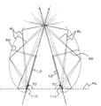
本発明の実施の一形態を図面を参照して以下に説明する。本実施の形態の発光装置100は、受光対象物(図示せず)を集光された光線RLで照明する発光装置100であって、図1および図2に示すように、光線RLを拡散して出射する面光源110と、断面形状が楕円形の一部からなり長軸方向LDの一端近傍に面光源110が位置するとともに他端が部分的に開口して光線RLを出射する反射面121を有する反射部材120と、反射部材120を長軸方向LDが面光源110側に傾斜した状態に配置する第一支持部材130と、面光源110を発光面が反射面121に対向するとともに受光対象物と対向する方向に傾斜した状態に配置する第二支持部材140と、を有する。
An embodiment of the present invention will be described below with reference to the drawings. The
より具体的には、面光源110は、図3に示すように、複数である四個のLEDセル111がマトリクス状に配列されているマトリクスLEDからなる。反射部材120は、光線RLを出射するために他端である上端が部分的に開口されている。
More specifically, as shown in FIG. 3, the
そして、反射部材120は、図2に示すように、反射面121が長軸方向LDと短軸方向SDとに略直交する方向に直線状に連続しており、その一端である下端近傍に、複数の面光源110が、反射面121の連続方向に配列されている。
As shown in FIG. 2, the reflecting
本実施の形態の発光装置100では、反射部材120は、左右方向に相対する一対からなり、複数の面光源110が、相対する一対の反射面121の各々の連続方向に配列されている。
In the
上述のような反射部材120は、例えば、表面の反射率が高いステンレスやアルミニウムの薄板などで形成することができる。なお、反射部材120の反射面121の表面は、金属膜または誘電体多層膜などの反射膜で覆われていてもよい。これにより、反射効率を高くできる。金属膜としては、例えば、銀、アルミニウム、などが挙げられる。
The
誘電体多層膜は、例えば、酸化チタン、酸化タリウム、酸化シリコン、フッ化マグネシウム、などがあげられる。また、金属膜または反射膜は、反射面121の全面に形成されていなくてもよく、一部または非連続的に形成されていてもよい。
Examples of the dielectric multilayer film include titanium oxide, thallium oxide, silicon oxide, and magnesium fluoride. Further, the metal film or the reflective film may not be formed on the entire surface of the
さらに、金属膜の上に保護膜を設けてもよい。これにより、金属膜を外気や水分などから保護できる。保護膜としては、例えば、シリコン酸化膜、シリコンと酸化チタンの多層増反射膜、などが挙げられる。 Furthermore, a protective film may be provided on the metal film. As a result, the metal film can be protected from the outside air and moisture. As the protective film, for example, a silicon oxide film, a multilayer reflection film made of silicon and titanium oxide, and the like can be given.
第一支持部材130は、本体端面部材131や反射支持板132などからなり、図1に示すように、反射部材120を長軸方向LDが面光源110側に傾斜した状態として、長軸方向LDが水平線HLから内側に86°に傾斜した状態に配置する。
The
第二支持部材140は、図2に示すように、装置本体141の上部中央の三角形状の突起部分からなり、図1に示すように、面光源110を発光面が反射面121に対向するとともに受光対象物と対向する方向に傾斜した状態として、水平線HLから発光面が66°などに傾斜した状態に配置する。第二支持部材140は、マトリクスLEDからなる複数の面光源110を駆動するドライバ回路や、冷却する冷却機構(図示せず)が内蔵されている。
As shown in FIG. 2, the
上述のような構成において、本実施の形態の発光装置100では、面光源110の発光面から拡散されて出射される光線RLが、反射部材120の反射面121で反射されて長軸方向LDの他端の開口から出射される。
In the configuration as described above, in the
ただし、この反射面121は断面形状が楕円形の一部からなり長軸方向LDが面光源110側に傾斜した状態に第一支持部材130で配置されており、面光源110は発光面が反射面121に対向するとともに受光対象物と対向する方向に傾斜した状態に第二支持部材140で配置されている。
However, the
このため、面光源110から出射されて反射面121で反射された光線RLを、点状や線状などに集光することができる。従って、紫外線で硬化するインク(図示せず)に光線RLを集中して照射し、短時間に硬化させることなどができる。
For this reason, the light ray RL emitted from the
さらに、マトリクスLED110の出射光は、ある程度の輝度分布および色度分布を持っている。しかし、本実施の形態の発光装置100では、反射面121で反射した光が、様々な方向から出射部に到達し、これらの光が混合した光を出射する。
Furthermore, the light emitted from the
このため、集光部における輝度分布および色度分布は、様々な方向から到達した光の輝度分布および色度分布が重畳したものとなる。これにより、集光される光線RLの輝度分布および色度分布の均一化が図れる。 For this reason, the luminance distribution and chromaticity distribution in the light condensing unit are superimposed with the luminance distribution and chromaticity distribution of the light arriving from various directions. As a result, the luminance distribution and chromaticity distribution of the collected light beam RL can be made uniform.
なお、本発明者は実際に上述のような発光装置100をシミュレートした。そのシミュレーションでは、反射面121の短軸を22mm、長軸を45mmとした。前述のように反射面121は長軸方向LDが水平線HLから内側に70°に傾斜した状態に配置し、面光源110は発光面が水平線HLから発光面が66°などに傾斜した状態に配置した。
The inventor actually simulated the
面光源110としては、その内部に四個のLEDセル111が2×2のマトリクス状に設置されている、紫外線LED(日亜化学工業株式会社製NC−4U−134)を想定した。
As the
マトリクスLED110から拡散されて出射される光線RLは大部分が一度だけ反射面121で反射されて線状に集光されることが確認された。その集光位置での出力は4W以上となり、紫外線硬化インクを高速に硬化させられることが確認された。
It was confirmed that most of the light rays RL diffused and emitted from the
[実施例]
なお、本発明者が実際に上述のような発光装置100を試作して確認したところ、反射部材120と面光源110との相対位置の誤差が性能に大幅に影響することが確認された。
[Example]
When the inventor actually made a prototype of the
反射部材120と面光源110との相対位置の誤差の原因と見込まれる誤差としては、
1.面光源110のハウジングと、その内部のLED素子との位置関係誤差=±0.2mm
2.面光源110のハウジングのサイズ誤差=±0.2mm
3.面光源110の基板(図示せず)への半田付け誤差=±0.1mm
4.面光源110の基板の半田ランドの位置誤差=±0.1mm
5.第一支持部材130と第二支持部材140との組立誤差=±0.1mm
6.第一支持部材130と反射部材120との組立誤差=±0.1mm
が想定される。
As an error that can be considered as a cause of an error in the relative position between the reflecting
1. Positional relationship error between the housing of the
2. Size error of housing of surface
3. Error in soldering surface
4). Position error of solder land of surface
5. Assembly error between
6). Assembly error between
Is assumed.
上記の各種誤差の二乗平均根の誤差は、
誤差=√(0.22+0.22+0.12+0.12+0.12+0.12)=0.35
となり、±0.35mmの誤差が発生する可能性があり、これは許容できない。
The error of the root mean square of the above errors is
Error = √ (0.2 2 +0.2 2 +0.1 2 +0.1 2 +0.1 2 +0.1 2 ) = 0.35
Therefore, an error of ± 0.35 mm may occur, which is unacceptable.
そこで、反射部材120と面光源110との相対位置を0.35mm以上、例えば、0.5mmほど調整できる機構を発光装置100に搭載する必要がある。例えば、面光源110と第二支持部材140との間にスプリングを配置し、面光源110を外周部の複数位置で第二支持部材140にビス止めすることにより、このビスで面光源110の方向を第二支持部材140に対して変位自在とする(図示せず)。
Therefore, it is necessary to mount on the light emitting device 100 a mechanism that can adjust the relative position between the reflecting
また、面光源110と第二支持部材140との間に楔状のスペーサを圧入できる構造とする(図示せず)。第一支持部材130や第二支持部材140をマイクロメータヘッドで可動できるように支持する(図示せず)。上述のような構造とすることで、反射部材120と面光源110との相対位置の誤差を補正することができる。
Further, a wedge-shaped spacer can be press-fitted between the
なお、本発明は本実施の形態に限定されるものではなく、その要旨を逸脱しない範囲で各種の変形を許容する。例えば、上記形態では反射部材120は、左右方向に相対する一対からなり、複数の面光源110が、相対する一対の反射面121の各々の連続方向に配列されていることを例示した。
The present invention is not limited to the present embodiment, and various modifications are allowed without departing from the scope of the present invention. For example, in the above embodiment, the reflecting
しかし、図4に示すように、反射部材120が一個しかなく、その下端近傍に面光源110が対向されていてもよい。また、図5に示すように、受光対象物を中心に略短軸方向SDに複数の反射部材220と複数の面光源110とが第一支持部材と第二支持部材とで配置されていてもよい。この場合、線状に集光される光線RLの輝度を向上させることができる。
However, as shown in FIG. 4, there may be only one reflecting
さらに、上述のように受光対象物を中心に略短軸方向SDに複数の反射部材220と複数の面光源110とが第一支持部材と第二支持部材とで配置されている構造が、同心円状に配列されていてもよい。
Furthermore, as described above, the structure in which the plurality of reflecting
さらに、上記形態では反射部材120は、図2に示すように、反射面121が長軸方向LDと短軸方向SDとに略直交する方向に直線状に連続しており、その一端である下端近傍に、複数の面光源110が、反射面121の連続方向に配列されていることを例示した。
Further, in the above embodiment, as shown in FIG. 2, the reflecting
しかし、図6に示すように、反射部材220が、反射面221が長軸方向LDと短軸方向SDとに略直交する方向に円形に連続しており、複数の面光源110が、反射面221と対向する円形に配置されていてもよい。この場合、複数の面光源110から出射された光線RLが点状に集中するので、この点状に光線RLを高輝度に集光させることができる。
However, as shown in FIG. 6, the reflecting
また、反射部材は、複数の反射面が長軸方向LDと短軸方向SDとに略直交する方向に多角形状に連続しており、複数の面光源110が、複数の反射面と個々に対向する位置に配置されていてもよい。この場合も、複数の面光源110から出射された光線RLが点状に集中するので、この点状に光線RLを高輝度に集光させることができる。
The reflecting member has a plurality of reflecting surfaces that are continuous in a polygonal shape in a direction substantially orthogonal to the major axis direction LD and the minor axis direction SD, and the plurality of surface
さらに、上記形態では断面形状が楕円形の一部からなる反射面121を有する反射部材120を例示した。しかし、反射面が完全に楕円形でなくともよく、楕円形から微妙に変形させた形状でもよい(図示せず)。
Furthermore, in the said form, the
なお、当然ながら、上述した実施の形態および複数の変形例は、その内容が相反しない範囲で組み合わせることができる。また、上述した実施の形態および変形例では、各部の構造などを具体的に説明したが、その構造などは本願発明を満足する範囲で各種に変更することができる。
以下、参考形態の例を付記する。
<1>
受光対象物を集光された光線で照明する発光装置であって、
前記光線を拡散して出射する面光源と、
断面形状が略楕円形の一部からなり長軸方向の一端近傍に前記面光源が位置するとともに他端が部分的に開口して前記光線を出射する反射面を有する反射部材と、
前記反射部材を前記長軸方向の他端が前記面光源側に傾斜した状態に配置する第一支持部材と、
前記面光源を発光面が前記反射面に対向するとともに前記受光対象物と対向する方向に傾斜した状態に配置する第二支持部材と、
を有する発光装置。
<2>
前記面光源は、複数のLED(Light Emitting Diode)セルがマトリクス状に配列されているマトリクスLEDからなる<1>記載の発光装置。
<3>
前記反射部材は、前記反射面が前記長軸方向と短軸方向とに略直交する方向に直線状に連続しており、
複数の前記面光源が、前記反射面の連続方向に配列されている<1>または<2>に記載の発光装置。
<4>
前記反射部材は、相対する一対からなり、
複数の前記面光源が、相対する一対の前記反射面の各々の連続方向に配列されている<3>に記載の発光装置。
<5>
前記反射部材は、複数の前記反射面が前記長軸方向と短軸方向とに略直交する方向に多角形状に連続しており、
複数の前記面光源が、複数の前記反射面と個々に対向する位置に配置されている<1>または<2>に記載の発光装置。
<6>
前記反射部材は、前記反射面が前記長軸方向と短軸方向とに略直交する方向に円形に連続しており、
複数の前記面光源が、前記反射面と対向する円形に配置されている<1>または<2>に記載の発光装置。
<7>
前記受光対象物を中心に略短軸方向に複数の前記反射部材と複数の前記面光源とが前記第一支持部材と前記第二支持部材とで配置されている<1>ないし<6>の何れか一項に記載の発光装置。
<8>
前記面光源から出射されて前記反射面で反射された前記光線が集光される位置に前記受光対象物を配置する対象配置機構を、さらに有する<1>ないし<7>の何れか一項に記載の発光装置。
Needless to say, the above-described embodiment and a plurality of modifications can be combined within a range in which the contents do not conflict with each other. Further, in the above-described embodiments and modifications, the structure of each part has been specifically described, but the structure and the like can be changed in various ways within a range that satisfies the present invention.
Hereinafter, examples of the reference form will be added.
<1>
A light-emitting device that illuminates a light-receiving object with a condensed light beam,
A surface light source that diffuses and emits the light beam;
A reflecting member having a reflecting surface in which the surface light source is located in the vicinity of one end in the major axis direction and the other end is partially opened and emits the light beam, the cross-sectional shape being a part of a substantially elliptical shape;
A first support member that arranges the reflecting member in a state in which the other end in the major axis direction is inclined toward the surface light source;
A second support member that arranges the surface light source in a state in which a light emitting surface faces the reflecting surface and is inclined in a direction facing the light receiving object;
A light emitting device.
<2>
<1> The light emitting device according to <1>, wherein the surface light source includes a matrix LED in which a plurality of LED (Light Emitting Diode) cells are arranged in a matrix.
<3>
The reflecting member is continuous in a straight line in a direction substantially orthogonal to the major axis direction and the minor axis direction of the reflecting surface,
The light emitting device according to <1> or <2>, wherein the plurality of surface light sources are arranged in a continuous direction of the reflecting surface.
<4>
The reflecting member is composed of a pair of opposed members,
The light emitting device according to <3>, wherein the plurality of surface light sources are arranged in a continuous direction of each of the pair of opposing reflecting surfaces.
<5>
The reflective member has a plurality of reflective surfaces continuous in a polygonal shape in a direction substantially orthogonal to the major axis direction and the minor axis direction,
The light emitting device according to <1> or <2>, wherein the plurality of surface light sources are arranged at positions individually facing the plurality of reflection surfaces.
<6>
The reflective member has a continuous circular shape in a direction in which the reflective surface is substantially orthogonal to the major axis direction and the minor axis direction;
The light emitting device according to <1> or <2>, in which the plurality of surface light sources are arranged in a circle facing the reflecting surface.
<7>
<1> to <6> in which a plurality of the reflection members and a plurality of the surface light sources are arranged in the substantially short axis direction around the light receiving object by the first support member and the second support member. The light emitting device according to any one of the above.
<8>
Any one of <1> to <7>, further including a target placement mechanism that places the light receiving object at a position where the light beam emitted from the surface light source and reflected by the reflection surface is collected. The light emitting device described.
100 発光装置
110 面光源
111 LEDセル
120 反射部材
121 反射面
130 第一支持部材
131 本体端面部材
132 反射支持板
140 第二支持部材
141 装置本体
220 反射部材
221 反射面
HL 水平線
LD 長軸方向
RL 光線
SD 短軸方向
DESCRIPTION OF
Claims (8)
断面形状が楕円形の一部からなり、前記楕円形の長軸方向の一端が部分的に開口し、前記楕円形の内側に光線を反射する反射面を有する反射部材と、
前記反射部材の前記長軸方向の他端近傍に位置し、発光面から光線を出射する面光源と、
を有し、
前記反射部材は前記長軸方向において前記面光源側に傾斜し、
前記面光源の前記発光面が前記反射面に対向するとともに前記受光対象物と対向する方向に傾斜し、
前記面光源から出射された光線を前記反射面で反射させて前記開口から出射させることにより集光させた光線で前記受光対象物を照明する発光装置。 A light-emitting device that illuminates a light-receiving object with a light beam,
A reflecting member having a reflecting surface that has a cross-sectional shape consisting of a part of an ellipse, one end of the ellipse in the major axis direction partially opens, and reflects light rays on the inner side of the ellipse;
A surface light source that is located near the other end in the major axis direction of the reflecting member and emits light from a light emitting surface;
Have
The reflecting member is inclined toward the surface light source in the major axis direction;
The light emitting surface of the surface light source is inclined in a direction facing the light receiving object while facing the reflecting surface,
A light emitting device that illuminates the light receiving object with a light beam condensed by reflecting the light beam emitted from the surface light source by the reflecting surface and emitting the light beam from the opening .
複数の前記面光源が、前記反射面の連続方向に配列されている請求項1に記載の発光装置。 The reflecting member is continuous in a straight line in a direction substantially orthogonal to the major axis direction and the minor axis direction of the reflecting surface,
The light emitting device according to claim 1, wherein the plurality of surface light sources are arranged in a continuous direction of the reflecting surface.
複数の前記面光源が、相対する一対の前記反射面の各々の連続方向に配列されている請求項2に記載の発光装置。 The reflecting member is composed of a pair of opposed members,
The light-emitting device according to claim 2, wherein the plurality of surface light sources are arranged in a continuous direction of each of the pair of opposing reflecting surfaces.
複数の前記面光源が、複数の前記反射面と個々に対向する位置に配置されている請求項1に記載の発光装置。 The reflective member has a plurality of reflective surfaces continuous in a polygonal shape in a direction substantially orthogonal to the major axis direction and the minor axis direction,
The light emitting device according to claim 1, wherein the plurality of surface light sources are arranged at positions individually facing the plurality of reflection surfaces.
複数の前記面光源が、前記反射面と対向する円形に配置されている請求項1に記載の発光装置。 The reflective member has a continuous circular shape in a direction in which the reflective surface is substantially orthogonal to the major axis direction and the minor axis direction;
The light-emitting device according to claim 1, wherein the plurality of surface light sources are arranged in a circle facing the reflecting surface.
前記面光源を前記発光面が前記反射面に対向するとともに前記受光対象物と対向する方向に傾斜した状態に配置する第二支持部材と、
前記面光源から出射されて前記反射面で反射された前記光線が集光される位置に前記受光対象物を配置する対象配置機構と、をさらに有する請求項1ないし7の何れか一項に記載の発光装置。 A first support member that arranges the reflecting member in a state in which the other end in the major axis direction is inclined toward the surface light source;
A second support member that arranges the surface light source in a state in which the light emitting surface faces the reflecting surface and is inclined in a direction facing the light receiving object;
The target deployment mechanism in which the light beam reflected by the reflection surface is emitted from the surface light source is disposed the light receiving object in a position to be focused, any one of claims 1 to 7 having the wo of al The light emitting device according to 1.
Priority Applications (1)
| Application Number | Priority Date | Filing Date | Title |
|---|---|---|---|
| JP2011062048A JP5668980B2 (en) | 2011-03-22 | 2011-03-22 | Light emitting device |
Applications Claiming Priority (1)
| Application Number | Priority Date | Filing Date | Title |
|---|---|---|---|
| JP2011062048A JP5668980B2 (en) | 2011-03-22 | 2011-03-22 | Light emitting device |
Publications (3)
| Publication Number | Publication Date |
|---|---|
| JP2012199055A JP2012199055A (en) | 2012-10-18 |
| JP2012199055A5 JP2012199055A5 (en) | 2014-05-15 |
| JP5668980B2 true JP5668980B2 (en) | 2015-02-12 |
Family
ID=47181094
Family Applications (1)
| Application Number | Title | Priority Date | Filing Date |
|---|---|---|---|
| JP2011062048A Expired - Fee Related JP5668980B2 (en) | 2011-03-22 | 2011-03-22 | Light emitting device |
Country Status (1)
| Country | Link |
|---|---|
| JP (1) | JP5668980B2 (en) |
Families Citing this family (3)
| Publication number | Priority date | Publication date | Assignee | Title |
|---|---|---|---|---|
| JP6305801B2 (en) * | 2014-03-19 | 2018-04-04 | 株式会社アイテックシステム | Lighting device |
| JP2016102864A (en) * | 2014-11-27 | 2016-06-02 | ファイベスト株式会社 | Optical module and method for manufacturing the same |
| JP6996920B2 (en) * | 2017-09-25 | 2022-01-17 | 東芝ライテック株式会社 | Light source device |
Family Cites Families (6)
| Publication number | Priority date | Publication date | Assignee | Title |
|---|---|---|---|---|
| US4814630A (en) * | 1987-06-29 | 1989-03-21 | Ncr Corporation | Document illuminating apparatus using light sources A, B, and C in periodic arrays |
| JP4870446B2 (en) * | 2005-03-10 | 2012-02-08 | 株式会社リコー | Document illumination device, image reading device, and image forming device |
| JP2006295810A (en) * | 2005-04-14 | 2006-10-26 | Canon Inc | Light source device and lighting device using same |
| JP2007013913A (en) * | 2005-05-30 | 2007-01-18 | Toyota Industries Corp | Lighting unit and original-reading apparatus |
| JP5292629B2 (en) * | 2009-01-09 | 2013-09-18 | 株式会社オプティックス | Lighting device |
| JP5665439B2 (en) * | 2010-09-07 | 2015-02-04 | 株式会社東芝 | LIGHTING DEVICE AND IMAGE READING DEVICE HAVING LIGHTING DEVICE |
-
2011
- 2011-03-22 JP JP2011062048A patent/JP5668980B2/en not_active Expired - Fee Related
Also Published As
| Publication number | Publication date |
|---|---|
| JP2012199055A (en) | 2012-10-18 |
Similar Documents
| Publication | Publication Date | Title |
|---|---|---|
| JP5077543B2 (en) | Vehicle lamp unit | |
| JP4047266B2 (en) | Lamp | |
| JP3931127B2 (en) | LIGHTING DEVICE AND DISPLAY DEVICE USING THE SAME | |
| RU2502919C2 (en) | Aligned lens for light diode lamp | |
| JP4113111B2 (en) | VEHICLE LIGHT UNIT AND VEHICLE LIGHTING LIGHT | |
| US10655808B2 (en) | Vehicle lamp | |
| JP2003317513A (en) | Light source unit | |
| JP5666977B2 (en) | Vehicle lighting | |
| JP5732127B2 (en) | Lighting device with smooth cut-off | |
| JP6539665B2 (en) | Sports lighting equipment | |
| JP5810327B2 (en) | lighting equipment | |
| JP7176211B2 (en) | lighting equipment | |
| US9494295B2 (en) | Ring light module | |
| WO2012141036A1 (en) | Reflective type lighting device | |
| WO2016158542A1 (en) | Light source device and lighting device | |
| JP2010161033A (en) | Illumination device | |
| JP2009087897A (en) | Optical part and vehicular lamp using the same | |
| JP5668980B2 (en) | Light emitting device | |
| JP2012256457A (en) | Vehicle headlamp | |
| JP2007294197A (en) | Lighting system | |
| JP2005129354A (en) | Led lighting device | |
| JP2019061905A (en) | Moving body illuminating device and moving body | |
| DK2587118T3 (en) | LED ceiling light | |
| JP6251081B2 (en) | Reflection unit and LED module | |
| JP2006073250A (en) | Lighting system |
Legal Events
| Date | Code | Title | Description |
|---|---|---|---|
| A521 | Written amendment |
Free format text: JAPANESE INTERMEDIATE CODE: A523 Effective date: 20140320 |
|
| A621 | Written request for application examination |
Free format text: JAPANESE INTERMEDIATE CODE: A621 Effective date: 20140320 |
|
| A871 | Explanation of circumstances concerning accelerated examination |
Free format text: JAPANESE INTERMEDIATE CODE: A871 Effective date: 20140320 |
|
| A975 | Report on accelerated examination |
Free format text: JAPANESE INTERMEDIATE CODE: A971005 Effective date: 20140521 |
|
| A131 | Notification of reasons for refusal |
Free format text: JAPANESE INTERMEDIATE CODE: A131 Effective date: 20140617 |
|
| A521 | Written amendment |
Free format text: JAPANESE INTERMEDIATE CODE: A523 Effective date: 20140818 |
|
| TRDD | Decision of grant or rejection written | ||
| A01 | Written decision to grant a patent or to grant a registration (utility model) |
Free format text: JAPANESE INTERMEDIATE CODE: A01 Effective date: 20141111 |
|
| A61 | First payment of annual fees (during grant procedure) |
Free format text: JAPANESE INTERMEDIATE CODE: A61 Effective date: 20141203 |
|
| R150 | Certificate of patent or registration of utility model |
Ref document number: 5668980 Country of ref document: JP Free format text: JAPANESE INTERMEDIATE CODE: R150 |
|
| LAPS | Cancellation because of no payment of annual fees |