JP5668564B2 - Sensitivity adjustment device and radio wave communication device - Google Patents
Sensitivity adjustment device and radio wave communication device Download PDFInfo
- Publication number
- JP5668564B2 JP5668564B2 JP2011066889A JP2011066889A JP5668564B2 JP 5668564 B2 JP5668564 B2 JP 5668564B2 JP 2011066889 A JP2011066889 A JP 2011066889A JP 2011066889 A JP2011066889 A JP 2011066889A JP 5668564 B2 JP5668564 B2 JP 5668564B2
- Authority
- JP
- Japan
- Prior art keywords
- sensitivity
- sensitivity adjustment
- segment
- antenna
- radio wave
- Prior art date
- Legal status (The legal status is an assumption and is not a legal conclusion. Google has not performed a legal analysis and makes no representation as to the accuracy of the status listed.)
- Active
Links
Images

Classifications
-
- Y02B60/50—
Landscapes
- Electric Clocks (AREA)
- Support Of Aerials (AREA)
- Transceivers (AREA)
Description
本発明は、感度調整装置及びこれを適用した電波通信機器に関するものである。 The present invention relates to a sensitivity adjustment device and a radio communication device to which the sensitivity adjustment device is applied.
近年、無線通信機能を備える電子機器間において、無線方式によってデータのやり取りをしたり、情報の同期を取る等、各種データの送受信(通信)を行う手法が浸透しつつある。
こうした無線通信によって送受信されるデータには個人情報も多く含まれる可能性がある。このため、個人のプライバシー等を保護するためにも、データの送受信は特定の電子機器から特定の電子機器に対して正確に行われる必要がある。
In recent years, methods for transmitting and receiving (communication) various types of data, such as exchanging data by a wireless method and synchronizing information between electronic devices having a wireless communication function, are spreading.
Data transmitted and received by such wireless communication may include a lot of personal information. For this reason, in order to protect personal privacy and the like, data transmission / reception needs to be accurately performed from a specific electronic device to a specific electronic device.
しかし、身の回りに複数の電子機器がある場合、他の電子機器との干渉が起こって目的の電子機器との間で正確に無線通信を行うことができないおそれがある。特にBluetooth(登録商標)など波長の長い電波を取り扱う際には、障害物等に強く電波が遮断されにくいという性質があるために、他の電子機器との干渉を起こしやすい。 However, when there are a plurality of electronic devices around the user, there is a possibility that interference with other electronic devices may occur and wireless communication cannot be performed accurately with the target electronic device. In particular, when handling radio waves having a long wavelength such as Bluetooth (registered trademark), the radio waves are strong against obstacles and are not easily cut off, and thus easily interfere with other electronic devices.
従来、無線通信システムにおいて、他の電子機器との干渉を避けて、通信を行いたい電子機器同士を適切にペアリングする方法として、ペアリングしたい電子機器(電子デバイス)を互いに近傍となる位置に配置するとともに、一方の電子機器から問い合わせ信号を送信し、他方の電子機器がこの問い合わせ信号を検出すると、これに対する応答信号を送信する。そして、当該電子機器が問い合わせ信号に応答する最初の電子機器であることに基づいて、双方の電子機器間で、ポイントツーポイント接続を開始するという手法が提案されている(例えば、特許文献1参照)。 2. Description of the Related Art Conventionally, in a wireless communication system, as a method of appropriately pairing electronic devices that are desired to communicate while avoiding interference with other electronic devices, the electronic devices (electronic devices) that are desired to be paired are positioned close to each other. In addition, when an inquiry signal is transmitted from one electronic device and the other electronic device detects this inquiry signal, a response signal is transmitted. Then, based on the fact that the electronic device is the first electronic device that responds to the inquiry signal, a method of starting point-to-point connection between both electronic devices has been proposed (see, for example, Patent Document 1). ).
しかし、この手法では、ペアリングしたい電子機器同士を近傍位置に配置する等が必要であり、ユーザにとって手間となる。また、ペアリングしたい相手の電子機器の位置が分からない場合もあり、必ずしも両電子機器を近傍位置に配置できるとは限らない。 However, with this method, it is necessary to arrange electronic devices to be paired in the vicinity of each other, which is troublesome for the user. Further, the position of the other electronic device to be paired may not be known, and it is not always possible to place both electronic devices in the vicinity.
そこで、他の電子機器との干渉を避けるためには、アンテナの送受信感度を低くして、目的とする電子機器以外との間では通信が成立しないようにしておくことも考えられる。 Therefore, in order to avoid interference with other electronic devices, it is conceivable to reduce the transmission / reception sensitivity of the antenna so that communication is not established with other devices than the target electronic device.
しかしながら、電子機器間でデータの送受信を行う目的は様々であり、例えばユーザ自身が身に着けている携帯端末装置と腕時計等の電子機器との間で各種データの送受信を行う場合のように極近距離で送受信を行う場合の他、ユーザが手元から離してしまった電子機器の所在を捜索する場合のようにある程度離れた場所にあると想定される電子機器との間で送受信を行う必要がある場合もある。 However, there are various purposes for transmitting and receiving data between electronic devices. For example, various types of data are transmitted and received between a mobile terminal device worn by the user and an electronic device such as a wristwatch. In addition to performing transmission / reception at a short distance, it is necessary to perform transmission / reception with an electronic device that is assumed to be located to some extent, such as when searching for the location of an electronic device that has been removed from the user. There can be.
前者の場合には、過度に送受信感度が高いと受信領域に通信可能な電子機器が多くなり、通信を行いたい相手を区別することが難しくなるため、送受信感度を低くすることが望まれる。これに対して、後者の場合には、送受信感度が低いと適切に捜索機能を果たすことができない。
このため、電子機器間でデータの送受信する際の電波の送受信感度は、その目的・用途に応じて適宜切り替えられることが求められる。
In the former case, if the transmission / reception sensitivity is excessively high, the number of electronic devices that can communicate with the reception area increases, and it becomes difficult to distinguish the other party with whom communication is desired. Therefore, it is desirable to reduce the transmission / reception sensitivity. On the other hand, in the latter case, if the transmission / reception sensitivity is low, the search function cannot be performed properly.
For this reason, the transmission / reception sensitivity of radio waves when transmitting / receiving data between electronic devices is required to be appropriately switched according to the purpose and application.
この点、携帯電話やパーソナルコンピュータ(personal computer)等では、受信回路等、通信関連モジュールにおいて送受信感度の切り替えを行っている。
しかし、特に、腕時計等の小型の電子機器では、バッテリの収容スペースに限りがあるため、できるだけ電力消費量を押えることが重要となるところ、この手法では、通信関連モジュールにおける電力消費量が多くなってしまうとの問題がある。
また、通信関連モジュールにおいて送受信感度の切り替えを行う場合、モジュール等の内部機構が複雑化することにより耐衝撃性能等に制限が出るおそれもある。
In this regard, in mobile phones, personal computers, and the like, transmission / reception sensitivity is switched in a communication-related module such as a receiving circuit.
However, especially in small electronic devices such as wristwatches, there is a limited battery storage space, so it is important to reduce power consumption as much as possible. This method increases the power consumption in communication-related modules. There is a problem with it.
In addition, when switching the transmission / reception sensitivity in the communication-related module, there is a possibility that the impact resistance and the like may be limited due to the complicated internal mechanism of the module.
本発明は以上のような事情に鑑みてなされたものであり、電力消費量を抑えつつ、簡易な機構により、用途に応じた感度となるようにアンテナの送受信感度を調整することのできる感度調整装置及びこれを適用した電波通信機器を提供することを目的とするものである。 The present invention has been made in view of the circumstances as described above, and sensitivity adjustment that can adjust the transmission / reception sensitivity of the antenna so that the sensitivity according to the application is achieved by a simple mechanism while suppressing power consumption. It is an object of the present invention to provide a device and a radio communication device to which the device is applied.
前記課題を解決するために、本発明に係る感度調整装置は、
外部の機器との間で無線信号を送受信可能なアンテナの電波送受信感度を調整する感度調整装置であって、
前記アンテナの近傍に配置され、個別のセグメントごとに点灯を制御可能である複数の感度調整用セグメントと、
通信時において前記感度調整用セグメントの点灯状態を制御することにより、前記アンテナの電波送受信感度を調整可能なセグメント点灯制御部と、
を備えていることを特徴としている。
In order to solve the above-described problem, a sensitivity adjustment device according to the present invention includes:
A sensitivity adjustment device that adjusts the radio wave transmission / reception sensitivity of an antenna capable of transmitting and receiving radio signals to and from an external device,
A plurality of segments for adjusting sensitivity, which are arranged in the vicinity of the antenna and can control lighting for each individual segment;
A segment lighting control unit capable of adjusting the radio wave transmission / reception sensitivity of the antenna by controlling the lighting state of the sensitivity adjustment segment during communication,
It is characterized by having.
また、本発明に係る電波通信機器は、
請求項1から請求項4のいずれか一項に記載の感度調整装置と、
前記感度調整装置により電波送受信感度を調整されるアンテナと、
を備えることを特徴としている。
The radio communication device according to the present invention is
The sensitivity adjustment device according to any one of
An antenna whose radio wave transmission / reception sensitivity is adjusted by the sensitivity adjustment device;
It is characterized by having.
本発明によれば、複数の感度調整用セグメントの点灯状態を制御するという簡易な手法により、アンテナの電波送受信感度を機械的な構成により迅速かつ確実に調整することができる。このため、受信回路等によってアンテナの電波送受信感度を調整する場合と比較して電力消費を抑えることができ、機械的な構成により、用途に応じたアンテナの送受信感度の調整を実現することができるという効果を奏する。 According to the present invention, the radio wave transmission / reception sensitivity of an antenna can be quickly and reliably adjusted with a mechanical configuration by a simple method of controlling lighting states of a plurality of sensitivity adjustment segments. For this reason, power consumption can be suppressed compared with the case where the radio wave transmission / reception sensitivity of the antenna is adjusted by a receiving circuit or the like, and the adjustment of the transmission / reception sensitivity of the antenna according to the application can be realized by a mechanical configuration. There is an effect.
以下、図面を参照して、本発明の好適な実施形態について説明する。なお、以下では、本発明に係る感度調整装置を、電波通信機器としての機能を備える腕時計に適用した場合について説明するが、本発明を適用可能な実施形態はこれに限定されるものではない。 Hereinafter, preferred embodiments of the present invention will be described with reference to the drawings. In the following, a case where the sensitivity adjustment device according to the present invention is applied to a wristwatch having a function as a radio communication device will be described, but embodiments to which the present invention can be applied are not limited thereto.
図1から図8を参照しつつ、本発明にかかる感度調整装置及びこれを備える腕時計の一実施形態について説明する。 An embodiment of a sensitivity adjusting device according to the present invention and a wristwatch including the same will be described with reference to FIGS.
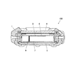
図1は、本実施形態に係る腕時計の腕時計本体の正面図、図2は、図1におけるII−II線断面図である。
本実施形態に係る腕時計100は、デジタル表示機能を備える表示部材としての液晶表示パネル15を備え、この液晶表示パネル15に時刻等を表示させるデジタル方式の腕時計である。
FIG. 1 is a front view of a wristwatch body of a wristwatch according to the present embodiment, and FIG. 2 is a sectional view taken along line II-II in FIG.
The
この腕時計100は、中空の短柱形状に形成された本体ケース1を備えている。この本体ケース1の上下両端部(図2及び図3において上下端部)、つまり時計の12時方向側端部及び6時方向側端部には、時計バンド(図示せず)が取り付けられるバンド取付部2が形成されている。
The
また、本体ケース1の外周部には、時刻合わせの指示、送受信感度の調節等を行うための種々の操作指示が入力される複数の操作ボタン3が設けられている。
本実施形態において、操作ボタン3は、後述するアンテナの電波送受信感度を異にする複数の通信モードを切り替えることができ、通信モード切替手段として機能するものである。
具体的には、後述するように、最も低い電波送受信感度の下で実現されるペアリングモード、標準的な電波送受信感度で実現されるデータ同期モード、最も高い電波送受信感度で実現される端末捜索モード/忘れ物防止モードが、操作ボタン3による入力操作により選択、切り替え可能となっている。
In addition, a plurality of
In the present embodiment, the
Specifically, as will be described later, a pairing mode realized with the lowest radio transmission / reception sensitivity, a data synchronization mode realized with the standard radio transmission / reception sensitivity, and a terminal search realized with the highest radio transmission / reception sensitivity The mode / thing left behind prevention mode can be selected and switched by an input operation using the
本体ケース1は、表面側(図2及び図3において上側)の開口部と、本体ケース1の裏面側(図2及び図3において下側)の開口部とを有している。そして、本体ケース1の表面側開口部には、透明なガラス等の材料で形成された風防ガラス4が表面側開口部を閉塞するように取り付けられている。一方、本体ケース1の裏面側開口部には、裏蓋部材5が裏面側開口部を閉塞するように取り付けられている。
The
本体ケース1の内部には、図示しないハウジングが設けられており、ハウジング内には各種電子部品を実装した回路基板7等が組み込まれている。
また、本体ケース1の内部であって、風防ガラス4とハウジングとの間には、デジタル表示機能を備える液晶表示手段としての液晶表示パネル6が配置されている。
この液晶表示パネル6と回路基板7とは、図示しないインターコネクタを介して電気的に接続されている。
液晶表示パネル6の裏面(視認側とは反対側の面)には、液晶表示パネル6を照明するバックライトとして、例えばEL(エレクトロルミネッセンス)素子を有するELパネル(図示せず)が設けられている。なお、バックライトはEL素子を有するものに限定されない。
A housing (not shown) is provided inside the
In addition, a liquid
The liquid
On the back surface of the liquid crystal display panel 6 (the surface opposite to the viewing side), for example, an EL panel (not shown) having an EL (electroluminescence) element is provided as a backlight for illuminating the liquid
また、液晶表示パネル6の裏面(図2において下側、腕時計100の裏面側)には、アンテナ8が設けられている。
本実施形態において、アンテナ8は、ループ状又はチップ状の小型のアンテナであり、例えばBluetooth(登録商標)等の規格により通信を行う。なお、アンテナ8の通信規格、通信可能な周波数帯は、Bluetooth(登録商標)に限定されず、腕時計100によって行われる各種通信に適したもの(すなわち、周波数等が適合するもの)が適宜適用される。また、アンテナ8は小型のものであればよく、種類、形状は特に限定されない。また、後述するように、本実施形態では、アンテナ8として、最大で5m程度の範囲内に存する機器との間で信号の送受信を行うことのできる電波送受信感度のものを適用しているが、アンテナ8の電波送受信感度はこれに限定されず、感度を最大としたときにさらに離れた機器との間で信号の送受信を行うことのできるものを用いてもよい。
このアンテナ8には、コイルスプリング等で形成され回路基板7と電気的に接続されたコネクタ9が接続されている。アンテナ8は、このコネクタ9を介して、後述する送受信制御回路部204と電気的に接続されている。
An
In this embodiment, the
A
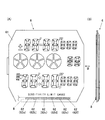
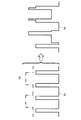
図3(A)は、本実施形態における液晶表示パネル6の平面図であり、図3(B)は、図3(A)に示す液晶表示パネル6を矢視Bから見た側面図である。
図3(B)に示すように、液晶表示パネル6は、例えば腕時計100に実装した際に視認側に配置される上部ガラス基板、視認側とは反対側に配置される下部ガラス基板、上部ガラス基板の上側に配置される上部偏光板、下部ガラス基板の下側に配置される下部偏光板等を備えた多層構造となっており、上部ガラス基板と下部ガラス基板との間には、図示しない液晶表示素子が封入されている。
FIG. 3A is a plan view of the liquid
As shown in FIG. 3B, the liquid
本実施形態において、液晶表示パネル6には、図3(A)に示すように、例えば、現在時刻や、秒表示、年月日表示、タイマ機能やストップウォッチ機能使用時におけるカウントダウン表示やカウントアップ表示等が表示される時刻等表示領域61と、アンテナ8の電波送受信感度を調整するための複数の感度調整用セグメント62が設けられている。なお、時刻等表示領域61に表示されるものはここに例示したものに限定されず、他の各種事項が表示されてもよい。
In the present embodiment, as shown in FIG. 3A, the liquid
本実施形態において、アンテナ8は、液晶表示パネル6の下側の端縁に沿って直線的に配置されており、複数の感度調整用セグメント62(62a〜62f)は、このアンテナ8の近傍に、アンテナ8に沿って配置されている。各感度調整用セグメント62(62a〜62f)は、後述するセグメント表示駆動回路部207bの制御により、個別のセグメントごとに点灯を制御可能となっている。
なお、本実施形態では6個の感度調整用セグメント62(62a〜62f)を直線的に設けた例を示しているが、感度調整用セグメント62の数や配置は図示例に限定されない。
In the present embodiment, the
In this embodiment, an example in which six sensitivity adjustment segments 62 (62a to 62f) are linearly provided is shown, but the number and arrangement of the
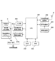
次に、図4を参照しつつ、本実施形態における腕時計100の機能的構成について説明する。
この腕時計100は、例えば、図4に示すように、入力部200、CPU(Central Processing Unit)201、ROM(Read Only Memory)202、RAM(Random Access Memory)203、受信制御回路部204、計時回路部205、発振回路部206、時刻等表示駆動回路部207a、セグメント表示駆動回路部207b等を備えて構成されている。
Next, the functional configuration of the
As shown in FIG. 4, for example, the
入力部200は、腕時計100の各種機能の実行を指示するための操作ボタン3等で操作されるスイッチからなり、ユーザによりこの操作ボタン3等が操作されると、これに基づいて、対応する操作信号をCPU201に対して出力するようになっている。
本実施形態では、腕時計100は、異なる電波送受信感度の下で実現される複数の通信モード(すなわち、本実施形態において「ペアリングモード」「データ同期モード」「端末捜索モード/忘れ物防止モード」)を実現可能であり、ユーザは操作ボタン3等を操作することにより、この通信モードを適宜切り替えることができる。入力部200は、操作ボタン3等の操作により通信モードを切り替える指示が入力されたときに、これに対応する操作信号をCPU201に対して出力する通信モード切替手段として機能する。
The
In the present embodiment, the
CPU201は、例えば、所定のタイミング或いは入力部200から入力された操作信号等に応じて、ROM202に格納されている各種プログラムを読み出してRAM203の作業領域に展開し、当該プログラムに従って腕時計100を構成する各部への指示やデータの転送等の各種処理を実行するものである。
具体的には、CPU201は、例えば、発振器を備える発振回路部206から出力される信号に基づき、計時回路部205で計数される現在時刻データを修正する処理や、修正された現在時刻データに基づく信号等を時刻等表示駆動回路部207aに出力して現在時刻等を表示させる処理等の各種制御を行う。
For example, the
Specifically, for example, the
また、本実施形態では、CPU201は、送受信制御回路部204を制御してアンテナ8から各種データを送信させたり、アンテナ8によって受信された各種データをRAM203に記憶させたり、当該データに基づいて各種処理を実行するように各部を制御したりする。
In the present embodiment, the
また、CPU201は、入力部200から通信モードを切り替える指示が入力されると、指示された通信モードに対応するアプリケーションプログラムをROM202から読み出して起動させるとともに、セグメント表示駆動回路部207bを制御して、感度調整用セグメント62a〜62fを適宜点灯、消灯させて、当該通信モードに適した電波送受信感度となるように調整する。
Further, when an instruction to switch the communication mode is input from the
ROM202は、読み出し専用のメモリであり、腕時計100の種々の機能を実現させるためのシステムプログラムや各種アプリケーションプログラム、各種データ等を記憶するものである。
本実施形態では、ROM202には、アプリケーションプログラムとして、ペアリングモード、データ同期モード、端末捜索モード/忘れ物防止モードを実現するためのプログラムが記憶されている。
RAM203は、例えば、揮発性の半導体メモリであり、CPU201により実行される各種プログラムや、これらのプログラムの実行に係るデータ等を一時的に保持するためのメモリ領域を備え、CPU201の作業領域として用いられる。
A
In the present embodiment, the
The
送受信制御回路部204は、アンテナ8で受信された受信信号から不要な周波数成分を取り除いて所定の周波数信号を取り出し、この周波数信号を対応する電気信号に変換してCPU201に出力する。
The transmission / reception
発振回路部206は、常時一定周波数のクロック信号を出力する回路であり、計時回路部205は、発振回路部206から入力される信号を計数して、現在時刻データ等を取得するものである。計時回路部205は、取得した現在時刻データをCPU201に対して出力するようになっている。
The
時刻等表示駆動回路部207aは、例えば、CPU201からのデータや制御信号等に基づいて時刻等表示領域61について液晶表示パネル6を駆動させ、現在時刻等を液晶表示パネル6の時刻等表示領域61に表示させるものである。
The time display drive circuit unit 207a drives the liquid
セグメント表示駆動回路部207bは、例えば、CPU201からの制御信号等に基づいて液晶表示パネル6の感度調整用セグメント62を駆動させ、入力部200等から入力指示された通信モードに対応する電波送受信感度となるように感度調整用セグメント62を点灯又は消灯させるものである。
本実施形態において、セグメント表示駆動回路部207bは、通信時において感度調整用セグメント62の点灯状態を制御することにより、アンテナ8の電波送受信感度を調整可能なセグメント点灯制御部として機能する。
また、このセグメント表示駆動回路部207bと複数の感度調整用セグメント62とによって、外部の機器である携帯電話などの他の端末装置Gのとの間で無線信号を送受信可能なアンテナ8の電波送受信感度を調整する感度調整装置60が構成されている。
The segment display
In the present embodiment, the segment display
In addition, the segment display
ここで、図5から図7を参照しつつ、感度調整用セグメント62a〜62fを適宜点灯、消灯させることによって、アンテナ8の電波送受信感度を調整する手法について説明する。
Here, a method of adjusting the radio wave transmission / reception sensitivity of the
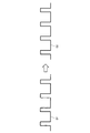
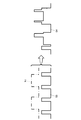
アンテナ8が電波を受信する際に何らノイズがない場合には、図5に示すように、外部機器から送信された信号S1(図5の矢印よりも左側)をそのまま受信し、その受信した信号S2(図5の矢印よりも右側)を識別することができる。
しかし、アンテナ8が電波を受信する際にノイズがある場合、図6に示すように、外部機器から送信された信号S3(図6の矢印よりも左側実線で示す)が弱い場合には、その信号にノイズN1(図6の矢印よりも左側一点鎖線で示す)が乗ると、図6の矢印よりも右側に示すように、信号パターンがノイズN1によって乱され、受信した信号S4を識別することができなくなる。
他方、アンテナ8が電波を受信する際にノイズがある場合であっても、図7に示すように、外部機器から送信された信号S5(図7の矢印よりも左側実線で示す)が強い場合には、その信号にノイズN2(図7の矢印よりも左側一点鎖線で示す)が乗っても、図7の矢印よりも右側に示すように、信号パターン自体は維持され、受信した信号S6を識別することができる。
If there is no noise when the
However, if there is noise when the
On the other hand, even when there is noise when the
液晶表示手段である感度調整用セグメント62a〜62fはアンテナ8の近傍に配置されていることから、通信時にこれを点灯させるとアンテナ8によって送受信される信号にノイズが乗る。点灯させる感度調整用セグメント62の数が多くなるほど、信号に乗るノイズの量は多くなり、他方で、アンテナ8によって送受信される信号はその距離が近いほど強く、距離が遠くなるほど弱くなる。
このため、点灯させる感度調整用セグメント62の数を増やして信号に乗るノイズの量を多くすると、近距離では信号として送受信することが可能だが遠距離では信号として識別することができなくなる。また、点灯させる感度調整用セグメント62の数を減らして信号に乗るノイズの量を少なくすると、遠距離でも信号として送受信することが可能となる。
そこで、信号の送受信を成立させたい距離に応じて点灯させる感度調整用セグメント62の数を調整することにより、アンテナ8の電波送受信感度を所望の通信モードに適したものに調整することができる。
Since the
For this reason, if the number of
Therefore, the radio wave transmission / reception sensitivity of the
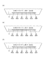
図8(A)から図8(C)は、各通信モードと感度調整用セグメント62a〜62fの点灯状態との関係を示したものである。図8(A)から図8(C)において、点灯している感度調整用セグメント62を斜線で示している。
図8(A)は、感度調整用セグメント62a〜62fを全て点灯させた場合であり、アンテナ8の電波送受信感度は最も低くなる。図8(B)は、6個の感度調整用セグメント62a〜62fのうち、3個のセグメント(62a〜62c)を点灯させた場合であり、アンテナ8の電波送受信感度は中程度となる。図8(C)は、6個の感度調整用セグメント62a〜62fのうち、1個のセグメント(62a)のみを点灯させた場合であり、アンテナ8の電波送受信感度は良好となる。
8A to 8C show the relationship between each communication mode and the lighting states of the
FIG. 8A shows a case where all the
本実施形態では、腕時計100は、通信モードとして、例えば、ペアリングモード、データ同期モード、端末捜索モード又忘れ物防止モードを実現可能となっている。
In the present embodiment, the
ペアリングモードは、例えばユーザが腕時計100と新たな端末装置G(例えば友人の端末装置等)との間で新たにペアリング(すなわち、端末装置間において相互に関連付けを行う初期登録)を成立させ、データの送受信等ができる状態にするための通信モードである。例えば腕時計100と新たな端末装置Gである友人の携帯電話との間でペアリングを行う場合には、腕時計100からペアリングしたい端末装置Gに対して問合せ信号を送信し、送信先の端末装置Gからこの問合せ信号に対する応答信号が腕時計100に送信され、腕時計100のアンテナ8がこの応答信号を受信してCPU201に送ると、腕時計100と当該端末装置Gとの間でペアリングが成立する。
入力部200からペアリングモードを選択する指示が入力されると、CPU201は、周囲に存する他の端末装置Gとの間で予期せぬペアリングが成立することのないように、腕時計100と端末装置Gとが接触又はそれに近い距離まで接近した場合にのみ電波の送受信が可能な程度までアンテナ8の電波送受信感度が低くなるように、感度調整装置60によりアンテナ8の電波送受信感度を調整する。
具体的には、例えば図8(A)に示す感度調整用セグメント62a〜62fを全て点灯させた点灯状態の場合がペアリングモードに対応する電波送受信感度となっており、ペアリングモードが選択されると、CPU201は、セグメント表示駆動回路部207bを制御して、感度調整用セグメント62a〜62fを全て点灯させる。
In the pairing mode, for example, the user establishes a new pairing (that is, initial registration for mutual association between terminal devices) between the
When an instruction to select a pairing mode is input from the
Specifically, for example, when the
また、データ同期モードは、例えば既に腕時計100との間でペアリングが成立している端末装置Gであって、ユーザが身につけている端末装置G等(例えば、ユーザの所持している図示しない携帯電話)、腕時計100の比較的近距離に位置する端末装置Gとの間でデータの同期を図ることを想定した通信モードである。
入力部200からデータ同期モードを選択する指示が入力されると、CPU201は、アンテナ8が1〜2m程度の範囲内に存する端末装置Gとの間で電波を送受信することのできる電波送受信感度となるように、感度調整装置60によりアンテナ8の電波送受信感度を調整する。
具体的には、例えば図8(B)に示す感度調整用セグメント62a〜62fのうち半分を点灯させた点灯状態の場合がデータ同期モードに対応する電波送受信感度となっており、データ同期モードが選択されると、CPU201は、セグメント表示駆動回路部207bを制御して、感度調整用セグメント62a〜62cを点灯させる。
The data synchronization mode is, for example, the terminal device G that has already been paired with the
When an instruction to select the data synchronization mode is input from the
Specifically, for example, when the lighting state in which half of the
また、端末捜索モードは、例えばユーザが腕時計100との間でペアリング済みである自己又は友人の端末装置G等の場所を捜索する場合を想定した通信モードであり、忘れ物防止モードは、例えばユーザが腕時計100との間でペアリング済みである自分の端末装置Gから所定の距離離れたときに、ブザー等により警告を発することを想定した通信モードである。
いずれの場合も、入力部200からこれらの通信モードを選択する指示が入力されると、CPU201は、アンテナ8が5m程度の範囲内に存する端末装置Gとの間で電波を送受信することのできる電波送受信感度となるように、感度調整装置60によりアンテナ8の電波送受信感度を調整する。
具体的には、例えば図8(C)に示す感度調整用セグメント62a〜62fのうち1個を点灯させた点灯状態の場合が端末捜索モード/忘れ物防止モードに対応する電波送受信感度となっており、端末捜索モード/忘れ物防止モードが選択されると、CPU201は、セグメント表示駆動回路部207bを制御して、感度調整用セグメント62aのみを点灯させる。
In addition, the terminal search mode is a communication mode that assumes a case where the user searches for a place such as the terminal device G of a self or friend who has been paired with the
In any case, when an instruction to select these communication modes is input from the
Specifically, for example, when one of the
なお、このように、点灯させる感度調整用セグメント62の数によってアンテナ8の電波送受信感度を切り替えることにより、ユーザは、感度調整用セグメント62の点灯状態を見れば直感的に容易に現在設定されている通信モードを知ることができ、感度調整用セグメント62が通信モードを示すインジケートとしての機能も果たすことができる。
In this way, by switching the radio wave transmission / reception sensitivity of the
次に、本実施形態における感度調整装置60及び電波通信機器である腕時計100の作用について説明する。
Next, the operation of the sensitivity adjustment device 60 and the
ユーザが腕時計100と自己や友人の端末装置G等との間で新たにペアリング(初期登録)を成立させ、腕時計100と当該端末装置Gとの間でデータの送受信等ができる状態にしたい場合には、操作ボタン3を操作して、通信モードとしてペアリングモードを選択する指示を入力すると、入力部200からCPU201にペアリングモードで通信を行うように指示信号が送られる。
CPU201は、指示信号を受けると、ペアリングモードを実現するためのアプリケーションプログラムをROM202から読み出して起動させるとともに、セグメント表示駆動回路部207bを制御して、感度調整用セグメント62a〜62fを全て点灯させる。
ユーザが、この状態でペアリングの対象となる端末装置Gを腕時計100に接触又は10cm程度の距離まで近接させると、腕時計100のアンテナ13からペアリングのための問合せ信号(例えば腕時計100の個体識別番号等を含む信号)が送信され、この問合せ信号を受信可能な距離にある端末装置Gのみが当該信号を受信する。問合せ信号を受信した端末装置Gは応答信号(例えば当該端末装置Gの個体識別番号等を含む信号)を腕時計100に返信し、腕時計100のアンテナ13がこの応答信号を受信すると、当該応答信号がCPU201に送られ、CPU201は当該端末装置Gを以後腕時計100との間でデータの送受信が可能な端末装置として登録する。これによりペアリングが成立し、CPU201は、LED36を点灯させて、ユーザにペアリングの成立を報知する。
なお、ペアリングモードに切り替えた上でユーザが腕時計100とペアリングの対象となる端末装置Gとを近づけてもペアリングが成立しない場合、すなわち、例えばペアリングモードでの通信を開始して一定時間が経過してもペアリングが成立した旨の表示がなされない場合には、ユーザが通信モードをデータ同期モード等、ペアリングモードよりもアンテナ13の電波送受信感度の高い通信モードに切り替えてさらにペアリングを試みることができるようにしてもよい。
When the user wishes to establish a new pairing (initial registration) between the
Upon receiving the instruction signal, the
In this state, when the terminal device G to be paired contacts the
If pairing is not established even if the user brings the
ユーザが既にペアリング(初期登録)が成立している端末装置Gと腕時計100との間でデータを送受信し、互いのデータを同期させたい場合には、操作ボタン3を操作して、通信モードとしてデータ同期モードを選択する指示を入力すると、入力部200からCPU201にデータ同期モードで通信を行うように指示信号が送られる。
CPU201は、指示信号を受けると、データ同期モードを実現するためのアプリケーションプログラムをROM202から読み出して起動させるとともに、セグメント表示駆動回路部207bを制御して、感度調整用セグメント62a〜62cを点灯させる。
これにより、腕時計100は、アンテナ13が1〜2m程度の範囲内に存する他の端末装置Gとの間で電波を送受信することのできる状態となり、例えばユーザが身に付けている携帯電話等、比較的近距離に位置する端末装置Gとの間でデータの送受信を行うことにより、相互のデータが同期される。
When the user wants to send and receive data between the terminal device G and the
Upon receiving the instruction signal, the
As a result, the
また、ユーザが既にペアリング(初期登録)が成立している端末装置Gの所在を腕時計100を用いて捜索したい場合や、端末装置Gが所定の距離以上離れた場合にその旨を通知して欲しい場合には、操作ボタン3を操作して、通信モードとして端末捜索モード/忘れ物防止モードを選択する指示を入力すると、入力部200からCPU201に端末捜索モード/忘れ物防止モードで通信を行うように指示信号が送られる。
CPU201は、指示信号を受けると、端末捜索モード/忘れ物防止モードを実現するためのアプリケーションプログラムをROM202から読み出して起動させるとともに、セグメント表示駆動回路部207bを制御して、感度調整用セグメント62aのみを点灯させる。
これにより、腕時計100のアンテナ13の電波送受信感度は最大となり、5m程度の範囲内に存する端末装置Gとの間で電波を送受信することのできる状態となる。
この場合、例えば端末捜索モードであれば、腕時計100から5m程度の範囲内に存するペアリング済みの端末装置Gに対して、腕時計100のアンテナ13から応答を要求する信号が送信され、端末装置Gがこの信号を受信して応答信号を腕時計100に送信すると、その旨がブザー等の音やLED36の点滅等によりユーザに報知される。また、例えば忘れ物防止モードであれば、腕時計100のアンテナ13からペアリング済みの端末装置Gに対して応答を要求する信号が送信され、端末装置Gはこの信号を受信して応答信号を腕時計100に送信する。そして、端末装置Gからの応答信号が受信できなくなると、CPU201は端末装置Gが所定の距離(本実施形態ではアンテナ13の電波送受信可能な範囲である5m)以上ユーザから離間したと判断して、その旨をブザー等の音や液晶表示パネル6への表示等によりユーザに報知する。
In addition, when the user wants to search the location of the terminal device G for which pairing (initial registration) has already been established using the
Upon receiving the instruction signal, the
Thereby, the radio wave transmission / reception sensitivity of the antenna 13 of the
In this case, for example, in the terminal search mode, a signal requesting a response is transmitted from the antenna 13 of the
以上のように、本実施形態によれば、異なる電波送受信感度の下で実現される複数の通信モード(例えばペアリングモード、データ同期モード、端末捜索モード/忘れ物防止モード)を実現可能であるため、ユーザの目的・用途に応じた各種の通信を行うことができる。
そして、アンテナ13の電波送受信感度をこれらの通信モードに応じた調整する手法として、複数の感度調整用セグメント62a〜6fの点灯状態を制御することにより、アンテナ8により送受信される信号に乗るノイズの量を調整するという機械的機構を用いているため、受信回路等、通信関連モジュールにおいて送受信感度の切り替えを行う場合と比較して、アンテナ13の電波送受信感度の調整にかかる電力消費量を抑えることができる。このため、腕時計100のように、大型のバッテリを収容するスペースのない電波通信機器においても適切にアンテナ13の電波送受信感度調整を行うことができる。
また、液晶表示パネル6の一部に設けられている感度調整用セグメント62の点灯数を変えるという簡易な構成によりアンテナ13の電波送受信感度を調整可能であるため、アンテナ13の電波送受信感度を調整するための別部材等を搭載する必要がなく、腕時計100等の電波通信機器の小型化・軽量化に資する。
さらに、本実施形態では、各通信モード(例えば「ペアリングモード」、「データ同期モード」、「端末捜索モード/忘れ物防止モード」)に対応して点灯させる感度調整用セグメント62の数を変えるようになっている。このため、感度調整用セグメント62が通信モードを示すインジケートとしての機能も果たすことができ、ユーザは、感度調整用セグメント62の点灯状態を見れば、現在設定されている通信モードを目視にて容易に直感的に知ることができる。
また、このように感度調整用セグメント62が電波送受信感度、通信モードを示すインジケートとしての機能も果たすため、電波送受信感度や通信モードを別途液晶表示パネル6の時刻等表示領域61に表示させる必要がなく、時刻等表示領域61を広く有効に利用することができる。
As described above, according to the present embodiment, it is possible to realize a plurality of communication modes (for example, the pairing mode, the data synchronization mode, the terminal search mode / the lost item prevention mode) realized under different radio wave transmission / reception sensitivities. Various communications according to the user's purpose and application can be performed.
Then, as a method of adjusting the radio wave transmission / reception sensitivity of the antenna 13 according to these communication modes, by controlling the lighting state of the plurality of
Further, since the radio wave transmission / reception sensitivity of the antenna 13 can be adjusted with a simple configuration in which the number of lighting of the
Furthermore, in the present embodiment, the number of
Further, since the
なお、以上本発明の実施形態について説明したが、本発明は、かかる実施形態に限定されず、その要旨を逸脱しない範囲で、種々変形が可能であることは言うまでもない。 Although the embodiments of the present invention have been described above, the present invention is not limited to such embodiments, and various modifications can be made without departing from the scope of the present invention.
例えば、上記実施形態では、各通信モード(例えば「ペアリングモード」、「データ同期モード」、「端末捜索モード/忘れ物防止モード」)に対応して点灯させる感度調整用セグメント62の数を変えることによりアンテナ8の電波送受信感度を調整する場合を例としたが、アンテナ8の電波送受信感度を調整するために切り替えられる感度調整用セグメント62の点灯状態は、点灯させる感度調整用セグメント62の数に限定されない。
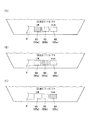
点灯する感度調整用セグメントがアンテナ8に近接するほど、アンテナ8によって送受信される信号に乗るノイズの量は多くなる。このため、例えば、図9(A)から図9(C)に示すように、アンテナ8からの位置を異にした複数の感度調整用セグメント65をアンテナ8の近傍に配置し、ペアリングモードで通信を行いたい場合のように、アンテナ8の電波送受信感度を低くしたい場合には、図9(A)に示すように、アンテナ8の真上等、アンテナに最も近い位置に配置された感度調整用セグメント65aを点灯させ、データ同期モードで通信を行いたい場合のように、アンテナ8の電波送受信感度を中程度にしたい場合には、図9(B)に示すように、アンテナ8の上に一部かかる位置に配置された感度調整用セグメント65bを点灯させ、端末捜索モード/忘れ物防止モードで通信を行いたい場合のように、アンテナ8の電波送受信感度を良好にしたい場合には、図9(C)に示すように、アンテナ8から離れた位置に配置された感度調整用セグメント65cを点灯させる。
この場合にも、ユーザは、点灯している感度調整用セグメント65の位置によって、現在設定されている通信モードを目視にて確認することができ、感度調整用セグメント65を、通信モードを示すインジケートとして機能させることができる。
また、図9(A)から図9(C)に示すように、各感度調整用セグメント65の上に、それぞれ「LOW」「HIGH」等、アンテナ8の電波送受信感度のレベルを示す文字を入れた場合には、より通信モードを認識しやすくなる。
For example, in the above-described embodiment, the number of
The closer the lit-up sensitivity adjustment segment is to the
Also in this case, the user can visually confirm the currently set communication mode according to the position of the lit
Also, as shown in FIGS. 9A to 9C, characters indicating the level of radio wave transmission / reception sensitivity of the
また、本実施形態では、アンテナ8の電波送受信感度を3段階に切り替えることができる場合を例示したが、切り替え可能な電波送受信感度は3段階に限定されない。さらに多くの段階に切り替え可能であってもよいし、無段階的に電波送受信感度を切り替えることができるように構成してもよい。
例えば、ペアリングモードにおいて、当初設定された電波送受信感度では上手くペアリングが成立しなかった場合に、ペアリングが成立する感度までユーザが手動で少しずつ電波送受信感度を上げていくことができるように構成してもよい。
Further, in the present embodiment, the case where the radio wave transmission / reception sensitivity of the
For example, in pairing mode, if pairing is not successful with the initially set radio transmission / reception sensitivity, the user can manually increase the radio transmission / reception sensitivity little by little until the pairing is established. You may comprise.
また、本実施形態では、アンテナ8の電波送受信感度のレベルと通信モードとが関連付けられ、例えばペアリングモードが選択されたときには、最もアンテナ8の電波送受信感度の低いレベル1(図9等において「LOW」)になるように、CPU及びセグメント表示駆動回路部が駆動することによって、各感度調整用セグメントの点灯を制御する構成としたが、各感度調整用セグメントの点灯を制御する構成はこのように通信モードの切り替えと電波送受信感度のレベルの切り替えとが連動し、通信モードの切り替えによって自動的に各感度調整用セグメントを点灯又は消灯させる構成に限定されない。例えば、ユーザが操作ボタン3等を操作することにより手動で所望の電波送受信感度となるまで感度調整用セグメントを点灯又は消灯させる構成としてもよい。
Further, in the present embodiment, the level of the radio wave transmission / reception sensitivity of the
また、本実施形態では、腕時計100がデジタル方式の腕時計である場合を例としたが、腕時計100は少なくとも一部に液晶表示パネルを備えるものであればよく、例えば指針を備えるアナログ式の時計と液晶表示パネル等のデジタル表示機能の両方を備えるものであってもよい。
In this embodiment, the
その他、本発明が本実施形態に限定されず、適宜変更可能であることはいうまでもない。 In addition, it cannot be overemphasized that this invention is not limited to this embodiment, and can be changed suitably.
以上本発明のいくつかの実施形態を説明したが、本発明の範囲は、上述の実施の形態に限定するものではなく、特許請求の範囲に記載された発明の範囲とその均等の範囲を含む。
以下に、この出願の願書に最初に添付した特許請求の範囲に記載した発明を付記する。付記に記載した請求項の項番は、この出願の願書に最初に添付した特許請求の範囲の通りである。
〔付記〕
<請求項1>
外部の機器との間で無線信号を送受信可能なアンテナの電波送受信感度を調整する感度調整装置であって、
前記アンテナの近傍に配置され、個別のセグメントごとに点灯を制御可能である複数の感度調整用セグメントと、
通信時において前記感度調整用セグメントの点灯状態を制御することにより、前記アンテナの電波送受信感度を調整可能なセグメント点灯制御部と、
を備えていることを特徴とする感度調整装置。
<請求項2>
異なる電波送受信感度の下で実現される複数の通信モードを実現可能であり、
前記通信モードを切り替え可能な通信モード切替手段をさらに備え、
前記セグメント点灯制御部は、前記通信モード切替手段により前記通信モードが切り替えられると、当該通信モードに適した電波送受信感度となるように前記感度調整用セグメントの点灯状態を制御するものであり、
前記感度調整用セグメントは、当該通信モードに適した電波送受信感度となる点灯状態となった際に、その点灯状態により当該通信モードをインジケートするように構成されていることを特徴とする請求項1に記載の感度調整装置。
<請求項3>
前記セグメント点灯制御部は、前記感度調整用セグメントの点灯状態として、前記感度調整用セグメントを点灯させる数又は位置の少なくともいずれか一方を制御するものであることを特徴とする請求項1又は請求項2に記載の感度調整装置。
<請求項4>
前記感度調整用セグメントは、液晶表示手段であることを特徴とする請求項1から請求項3のいずれか一項に記載の感度調整装置。
<請求項5>
請求項1から請求項4のいずれか一項に記載の感度調整装置と、
前記感度調整装置により電波送受信感度を調整されるアンテナと、
を備えることを特徴とする電波通信機器。
Although several embodiments of the present invention have been described above, the scope of the present invention is not limited to the above-described embodiments, but includes the scope of the invention described in the claims and equivalents thereof. .
The invention described in the scope of claims attached to the application of this application will be added below. The item numbers of the claims described in the appendix are as set forth in the claims attached to the application of this application.
[Appendix]
<Claim 1>
A sensitivity adjustment device that adjusts the radio wave transmission / reception sensitivity of an antenna capable of transmitting and receiving radio signals to and from an external device,
A plurality of segments for adjusting sensitivity, which are arranged in the vicinity of the antenna and can control lighting for each individual segment;
A segment lighting control unit capable of adjusting the radio wave transmission / reception sensitivity of the antenna by controlling the lighting state of the sensitivity adjustment segment during communication,
A sensitivity adjusting device comprising:
<Claim 2>
It is possible to realize multiple communication modes realized under different radio wave transmission / reception sensitivities,
A communication mode switching means capable of switching the communication mode;
When the communication mode is switched by the communication mode switching unit, the segment lighting control unit controls the lighting state of the sensitivity adjustment segment so that the radio wave transmission / reception sensitivity suitable for the communication mode is obtained.
2. The sensitivity adjustment segment is configured to indicate the communication mode according to a lighting state when the lighting state becomes a radio wave transmission / reception sensitivity suitable for the communication mode. Sensitivity adjusting device described in 1.
<Claim 3>
The said segment lighting control part controls at least any one of the number or position which the said segment for sensitivity adjustment lights as a lighting state of the said segment for sensitivity adjustment, The
<Claim 4>
The sensitivity adjustment apparatus according to any one of
<Claim 5>
The sensitivity adjustment device according to any one of
An antenna whose radio wave transmission / reception sensitivity is adjusted by the sensitivity adjustment device;
A radio communication device comprising:
1 本体ケース
8 アンテナ
60 感度調整装置
62 感度調整用セグメント
100 腕時計
207b セグメント表示駆動回路部
DESCRIPTION OF
Claims (5)
前記アンテナの近傍に配置され、個別のセグメントごとに点灯を制御可能である複数の感度調整用セグメントと、
通信時において前記感度調整用セグメントの点灯状態を制御することにより、前記アンテナの電波送受信感度を調整可能なセグメント点灯制御部と、
を備えていることを特徴とする感度調整装置。 A sensitivity adjustment device that adjusts the radio wave transmission / reception sensitivity of an antenna capable of transmitting and receiving radio signals to and from an external device,
A plurality of segments for adjusting sensitivity, which are arranged in the vicinity of the antenna and can control lighting for each individual segment;
A segment lighting control unit capable of adjusting the radio wave transmission / reception sensitivity of the antenna by controlling the lighting state of the sensitivity adjustment segment during communication,
A sensitivity adjusting device comprising:
前記通信モードを切り替え可能な通信モード切替手段をさらに備え、
前記セグメント点灯制御部は、前記通信モード切替手段により前記通信モードが切り替えられると、当該通信モードに適した電波送受信感度となるように前記感度調整用セグメントの点灯状態を制御するものであり、
前記感度調整用セグメントは、当該通信モードに適した電波送受信感度となる点灯状態となった際に、その点灯状態により当該通信モードをインジケートするように構成されていることを特徴とする請求項1に記載の感度調整装置。 It is possible to realize multiple communication modes realized under different radio wave transmission / reception sensitivities,
A communication mode switching means capable of switching the communication mode;
When the communication mode is switched by the communication mode switching unit, the segment lighting control unit controls the lighting state of the sensitivity adjustment segment so that the radio wave transmission / reception sensitivity suitable for the communication mode is obtained.
2. The sensitivity adjustment segment is configured to indicate the communication mode according to a lighting state when the lighting state becomes a radio wave transmission / reception sensitivity suitable for the communication mode. Sensitivity adjusting device described in 1.
前記感度調整装置により電波送受信感度を調整されるアンテナと、
を備えることを特徴とする電波通信機器。 The sensitivity adjustment device according to any one of claims 1 to 4,
An antenna whose radio wave transmission / reception sensitivity is adjusted by the sensitivity adjustment device;
A radio communication device comprising:
Priority Applications (1)
| Application Number | Priority Date | Filing Date | Title |
|---|---|---|---|
| JP2011066889A JP5668564B2 (en) | 2011-03-25 | 2011-03-25 | Sensitivity adjustment device and radio wave communication device |
Applications Claiming Priority (1)
| Application Number | Priority Date | Filing Date | Title |
|---|---|---|---|
| JP2011066889A JP5668564B2 (en) | 2011-03-25 | 2011-03-25 | Sensitivity adjustment device and radio wave communication device |
Publications (2)
| Publication Number | Publication Date |
|---|---|
| JP2012205026A JP2012205026A (en) | 2012-10-22 |
| JP5668564B2 true JP5668564B2 (en) | 2015-02-12 |
Family
ID=47185536
Family Applications (1)
| Application Number | Title | Priority Date | Filing Date |
|---|---|---|---|
| JP2011066889A Active JP5668564B2 (en) | 2011-03-25 | 2011-03-25 | Sensitivity adjustment device and radio wave communication device |
Country Status (1)
| Country | Link |
|---|---|
| JP (1) | JP5668564B2 (en) |
Families Citing this family (2)
| Publication number | Priority date | Publication date | Assignee | Title |
|---|---|---|---|---|
| JP6269240B2 (en) * | 2014-03-27 | 2018-01-31 | カシオ計算機株式会社 | Clock and communication system |
| JP6589973B2 (en) * | 2017-12-26 | 2019-10-16 | カシオ計算機株式会社 | Electronic device and communication system |
Family Cites Families (8)
| Publication number | Priority date | Publication date | Assignee | Title |
|---|---|---|---|---|
| US5012A (en) * | 1847-03-13 | Cutting- stone | ||
| JP4337178B2 (en) * | 1999-07-14 | 2009-09-30 | カシオ計算機株式会社 | Receiver with display |
| JP4649747B2 (en) * | 2001-02-20 | 2011-03-16 | 三菱電機株式会社 | Programmable display |
| JP2007116626A (en) * | 2005-10-24 | 2007-05-10 | Canon Inc | Control circuit |
| JP4079197B1 (en) * | 2007-02-06 | 2008-04-23 | 松下電器産業株式会社 | Receiving apparatus and receiving system using the same |
| JP2008215929A (en) * | 2007-03-01 | 2008-09-18 | Citizen Holdings Co Ltd | Radio-controlled timepiece |
| JP5154966B2 (en) * | 2008-02-12 | 2013-02-27 | 富士通株式会社 | Method, program, and apparatus for controlling receiver sensitivity of receiver |
| JP2012089276A (en) * | 2010-10-18 | 2012-05-10 | Panasonic Corp | Illumination control device |
-
2011
- 2011-03-25 JP JP2011066889A patent/JP5668564B2/en active Active
Also Published As
| Publication number | Publication date |
|---|---|
| JP2012205026A (en) | 2012-10-22 |
Similar Documents
| Publication | Publication Date | Title |
|---|---|---|
| US8902716B2 (en) | Sensitivity adjustment device, radio wave communication device and watch | |
| EP3023845B1 (en) | Band type electronic device | |
| TWI483572B (en) | System and methods for performing antenna transmit diversity | |
| JP5454533B2 (en) | Electronic clock | |
| JP2013064723A5 (en) | ||
| US20150168920A1 (en) | Electronic timepiece and operation setting switching system | |
| JP5668564B2 (en) | Sensitivity adjustment device and radio wave communication device | |
| JP5935422B2 (en) | Sensitivity adjustment device and radio wave communication device | |
| JP5776359B2 (en) | Sensitivity adjusting device and wristwatch | |
| JP6553684B2 (en) | Input device and manufacturing method thereof | |
| JP5811619B2 (en) | Sensitivity adjusting device and wristwatch | |
| JP2012205025A (en) | Sensitivity adjustment device and radio wave communication device | |
| JP2011112472A (en) | Wrist-mounted type terminal and time correction method | |
| EP3091402A1 (en) | Mobile phone in the form of a wristwatch | |
| JP5227097B2 (en) | Portable electronic devices | |
| WO2006131985A1 (en) | Electronic device and cover | |
| JP5803593B2 (en) | Sensitivity adjustment device and radio wave communication device | |
| JP2014077800A (en) | Electronic watch | |
| KR200320647Y1 (en) | A table clock emitting sound to notice the receipt of a cell phone call | |
| JP5810680B2 (en) | Pointer type clock | |
| JP5227096B2 (en) | Portable electronic devices | |
| JP2013047628A (en) | Sensitivity adjustment device and wrist watch | |
| US20190302703A1 (en) | Timepiece with Enhanced Antenna Arrangement | |
| JP2010011239A (en) | Portable electronic equipment | |
| KR200382874Y1 (en) | A Detached Accessorial Device for Recognizing Incoming Call at Cellular Phone |
Legal Events
| Date | Code | Title | Description |
|---|---|---|---|
| A621 | Written request for application examination |
Free format text: JAPANESE INTERMEDIATE CODE: A621 Effective date: 20140307 |
|
| A977 | Report on retrieval |
Free format text: JAPANESE INTERMEDIATE CODE: A971007 Effective date: 20141112 |
|
| TRDD | Decision of grant or rejection written | ||
| A01 | Written decision to grant a patent or to grant a registration (utility model) |
Free format text: JAPANESE INTERMEDIATE CODE: A01 Effective date: 20141118 |
|
| A61 | First payment of annual fees (during grant procedure) |
Free format text: JAPANESE INTERMEDIATE CODE: A61 Effective date: 20141201 |
|
| R150 | Certificate of patent or registration of utility model |
Ref document number: 5668564 Country of ref document: JP Free format text: JAPANESE INTERMEDIATE CODE: R150 |