JP5666090B2 - Interconnection system for energy storage assemblies - Google Patents
Interconnection system for energy storage assemblies Download PDFInfo
- Publication number
- JP5666090B2 JP5666090B2 JP2008520907A JP2008520907A JP5666090B2 JP 5666090 B2 JP5666090 B2 JP 5666090B2 JP 2008520907 A JP2008520907 A JP 2008520907A JP 2008520907 A JP2008520907 A JP 2008520907A JP 5666090 B2 JP5666090 B2 JP 5666090B2
- Authority
- JP
- Japan
- Prior art keywords
- circuit
- cell
- current shunt
- energy storage
- storage
- Prior art date
- Legal status (The legal status is an assumption and is not a legal conclusion. Google has not performed a legal analysis and makes no representation as to the accuracy of the status listed.)
- Expired - Fee Related
Links
Images


Classifications
-
- H—ELECTRICITY
- H01—ELECTRIC ELEMENTS
- H01M—PROCESSES OR MEANS, e.g. BATTERIES, FOR THE DIRECT CONVERSION OF CHEMICAL ENERGY INTO ELECTRICAL ENERGY
- H01M50/00—Constructional details or processes of manufacture of the non-active parts of electrochemical cells other than fuel cells, e.g. hybrid cells
- H01M50/50—Current conducting connections for cells or batteries
- H01M50/502—Interconnectors for connecting terminals of adjacent batteries; Interconnectors for connecting cells outside a battery casing
- H01M50/509—Interconnectors for connecting terminals of adjacent batteries; Interconnectors for connecting cells outside a battery casing characterised by the type of connection, e.g. mixed connections
- H01M50/51—Connection only in series
-
- H—ELECTRICITY
- H01—ELECTRIC ELEMENTS
- H01M—PROCESSES OR MEANS, e.g. BATTERIES, FOR THE DIRECT CONVERSION OF CHEMICAL ENERGY INTO ELECTRICAL ENERGY
- H01M50/00—Constructional details or processes of manufacture of the non-active parts of electrochemical cells other than fuel cells, e.g. hybrid cells
- H01M50/50—Current conducting connections for cells or batteries
- H01M50/502—Interconnectors for connecting terminals of adjacent batteries; Interconnectors for connecting cells outside a battery casing
- H01M50/505—Interconnectors for connecting terminals of adjacent batteries; Interconnectors for connecting cells outside a battery casing comprising a single busbar
-
- H—ELECTRICITY
- H01—ELECTRIC ELEMENTS
- H01M—PROCESSES OR MEANS, e.g. BATTERIES, FOR THE DIRECT CONVERSION OF CHEMICAL ENERGY INTO ELECTRICAL ENERGY
- H01M50/00—Constructional details or processes of manufacture of the non-active parts of electrochemical cells other than fuel cells, e.g. hybrid cells
- H01M50/50—Current conducting connections for cells or batteries
- H01M50/502—Interconnectors for connecting terminals of adjacent batteries; Interconnectors for connecting cells outside a battery casing
- H01M50/521—Interconnectors for connecting terminals of adjacent batteries; Interconnectors for connecting cells outside a battery casing characterised by the material
- H01M50/522—Inorganic material
-
- Y—GENERAL TAGGING OF NEW TECHNOLOGICAL DEVELOPMENTS; GENERAL TAGGING OF CROSS-SECTIONAL TECHNOLOGIES SPANNING OVER SEVERAL SECTIONS OF THE IPC; TECHNICAL SUBJECTS COVERED BY FORMER USPC CROSS-REFERENCE ART COLLECTIONS [XRACs] AND DIGESTS
- Y02—TECHNOLOGIES OR APPLICATIONS FOR MITIGATION OR ADAPTATION AGAINST CLIMATE CHANGE
- Y02E—REDUCTION OF GREENHOUSE GAS [GHG] EMISSIONS, RELATED TO ENERGY GENERATION, TRANSMISSION OR DISTRIBUTION
- Y02E60/00—Enabling technologies; Technologies with a potential or indirect contribution to GHG emissions mitigation
- Y02E60/10—Energy storage using batteries
-
- Y—GENERAL TAGGING OF NEW TECHNOLOGICAL DEVELOPMENTS; GENERAL TAGGING OF CROSS-SECTIONAL TECHNOLOGIES SPANNING OVER SEVERAL SECTIONS OF THE IPC; TECHNICAL SUBJECTS COVERED BY FORMER USPC CROSS-REFERENCE ART COLLECTIONS [XRACs] AND DIGESTS
- Y10—TECHNICAL SUBJECTS COVERED BY FORMER USPC
- Y10T—TECHNICAL SUBJECTS COVERED BY FORMER US CLASSIFICATION
- Y10T29/00—Metal working
- Y10T29/49—Method of mechanical manufacture
- Y10T29/49002—Electrical device making
- Y10T29/49108—Electric battery cell making
- Y10T29/49115—Electric battery cell making including coating or impregnating
Description
本発明の分野は、エネルギー蓄積組立品の技術に関する。より正確には、本発明は、エネルギー蓄積組立品をこれの健全状態を制御する電子装置サポーターと相互接続するためのシステムおよび方法に関する。 The field of the invention relates to the technology of energy storage assemblies. More precisely, the present invention relates to a system and method for interconnecting an energy storage assembly with an electronic device supporter that controls its health .
本発明は、また、そのような相互接続システムを備えたエネルギー蓄積組立品にも関する。 The invention also relates to an energy storage assembly comprising such an interconnection system.
エネルギー蓄積組立品の商業的用途の大部分で、特に自動車用途で要求される必要なエネルギー生成を満たすために、最近、例えばリチウムポリマー技術などの高エネルギー技術と呼ばれる多くの技術が開発された。 In order to meet the required energy production required for most commercial applications of energy storage assemblies, especially in automotive applications, a number of technologies have recently been developed, referred to as high energy technologies such as lithium polymer technology.
そのような技術には、エネルギー蓄積組立品の製造業者側での改善、特に、この組立品を監視するための接続の性能を最適化する分野での改善を必要とする特徴がある。 Such techniques have features that require improvements on the energy storage assembly manufacturer's side, particularly in the area of optimizing the performance of connections for monitoring the assembly.
現在は、高エネルギー蓄積組立品の典型的な動作方法において、その組立品の構成要素のエネルギー蓄積セルの1つが、所望のエネルギー・レベルを生成するために接続されているその他のセルの特性と著しく異なる特性を有しているとき、その組立品の充電または放電中に望ましくない現象が生じることは、よく知られている。 Currently, in a typical method of operation of a high energy storage assembly, one of the component energy storage cells of that assembly is characterized by the characteristics of the other cells connected to produce the desired energy level. It is well known that undesirable phenomena occur during charging or discharging of an assembly when it has significantly different properties.
電圧スパイクまたは過負荷は、欠陥のあるセルが存在することで引き起こされる現象の例である。これらは、エネルギー蓄積組立品の性能を低下させ、平均寿命を減少させる。 A voltage spike or overload is an example of a phenomenon caused by the presence of a defective cell. These reduce the performance of the energy storage assembly and reduce the average life.
エネルギー蓄積組立品の従来モデルの一態様によれば、エネルギー蓄積セルを監視し、かつこれらの現象からエネルギー蓄積セルを保護するために、プログラム可能な電子装置サポーターが構造の中に組み込まれる。 According to one aspect of a conventional model of an energy storage assembly, programmable electronic device supporters are incorporated into the structure to monitor the energy storage cell and protect the energy storage cell from these phenomena.
このサポーターは、まず第1に、その組立品の各エネルギー蓄積セルの極性端子にケーブル配線された測定回路によって、セルの健全状態についての様々な特性を収集する。 The supporter first collects various characteristics about the health of the cell by means of a measurement circuit cabled to the polarity terminal of each energy storage cell of the assembly.
さらに、このサポーターはセルに接続された電流分流回路を監視し、この電流分流回路は、その組立品の損傷を防ぐために、予め設定された電圧レベルが超えられたとき電流を個々のセルの周りにそらす。 In addition, the supporter monitors the current shunt circuit connected to the cell, which current shunts around the individual cells when a preset voltage level is exceeded to prevent damage to the assembly. Distract.
この型の回路に一般に存在する部分的に監視された電子分流部品も、つまり詳細には電力損失抵抗も、各エネルギー蓄積セルの最上部にケーブル配線されなければならない。Both the partially monitored electronic shunt components that are commonly present in this type of circuit, in particular the power loss resistance, must be cabled on top of each energy storage cell.
従来のエネルギー蓄積組立品の製造で通常使用される配線ケーブル・システムは、一般に複雑である。また、この配線ケーブル・システムは、セルを異なる回路に接続するための可撓性をほとんど備えていない。 The wiring cable system normally used in the manufacture of conventional energy storage assemblies is generally complex. Also, this distribution cable system provides little flexibility for connecting cells to different circuits.
さらに、ケーブルの取り付けは、厄介で、高価であり、さらに、どちらかと言えば時間がかかる。 Furthermore, cable installation is cumbersome, expensive, and rather time consuming.
このケーブル・システムも電磁干渉に非常に敏感であり、前記電磁干渉は線に沿った伝導によって伝播し、かつ、前記電磁干渉は、望ましくない現象、例えば、短絡および電気的干渉を監視サポーターまたは制御サポーターに生じさせる。This cable system is also very sensitive to electromagnetic interference, which propagates by conduction along the line, and the electromagnetic interference monitors or supports undesirable phenomena such as short circuits and electrical interference Create a supporter.
一体型電子電力損失部品−その役割は、電流通路に高抵抗を与え、それにより、エネルギー蓄積セルによって出力される電力を制限し、そのセルの中での熱の発生を増大させることにある−は、放出エネルギー表面密度が非常に高い。これらの密度の回復(リカバリー:正常な状態に戻すこと)は難しいので、それらはセルを損傷する。 Integrated electronic power loss component—its role is to provide high resistance to the current path, thereby limiting the power output by the energy storage cell and increasing the generation of heat in the cell— Has a very high emission energy surface density. Since these density recoveries (recovery: returning to normal) are difficult, they damage the cells.
本発明は、特に、従来技術の欠点を克服することを目的とする。 The present invention is particularly aimed at overcoming the drawbacks of the prior art.
本発明の1つの目的は、組立品のエネルギー蓄積セルを、この組立品の健全状態を監視するために使用される電子装置サポーターと相互接続するためのシステムを提案することであり、このシステムは、単純で、撓み可能で、安全で、かつ信頼性のある接続を実現する。 One object of the present invention is to propose a system for interconnecting an energy storage cell of an assembly with an electronic device supporter used to monitor the health of the assembly. A simple, flexible, safe and reliable connection.
本発明の他の目的は、接続の実効精度を依然として維持しながら、特に3次元において相当に大きな幾何学的構成の自由度を持った相互接続システムを与えることである。 Another object of the present invention is to provide an interconnection system with a considerable degree of geometric freedom, particularly in three dimensions, while still maintaining the effective accuracy of the connection.
エネルギー蓄積組立品を作るとき、コスト、重量およびスペースの点で明らかな節約を与える相互接続システムを提案することが、また、望ましい。 It is also desirable to propose an interconnect system that provides a clear savings in cost, weight and space when making an energy storage assembly.
本発明の他の目的は、エネルギー蓄積組立品の性能に及ぼす欠陥セルの影響を和らげ、かつこの組立品での効率のよいエネルギー散逸をもたらす相互接続システムを与えることである。 Another object of the present invention is to provide an interconnect system that mitigates the effects of defective cells on the performance of the energy storage assembly and provides efficient energy dissipation in the assembly.
これらの目的は、本発明に従って、エネルギー蓄積組立品を形成するために電気的に接続されたエネルギー蓄積セルを電子制御サポーターと一緒に相互接続するシステムによって達成され、前記のエネルギー蓄積セルの各々はその最上部に極性端子を備え、相互接続システムは、相互接続支持物を含むことを特徴とする、前記のサポーターは導電性表面に形成された伝導回路を含み、前記の回路は、電子制御サポーターと、それぞれ接続手段を使用し保持手段を使用して前記回路が接続された極性端子との間に電気接続を形成し、前記の保持手段は、まず第1に、相互接続支持物の上に極性端子を配置するために、極性端子上で支持手段と接触するように設計され、さらに、前記の保持手段は、極性端子と伝導回路の間に直接電気接続を作るように設計されている。 These objects are achieved in accordance with the present invention by a system for interconnecting electrically storage energy storage cells together with electronic control supporters to form an energy storage assembly, each of said energy storage cells being The supporter includes a conductive circuit formed on a conductive surface, the supporter comprising a polar terminal at its top and the interconnect system includes an interconnect support, the circuit comprising an electronic control supporter And each of the connecting means and the holding means to form an electrical connection with the polarity terminal to which the circuit is connected, the holding means firstly on the interconnect support In order to place the polar terminal, it is designed to contact the support means on the polar terminal, and said holding means make a direct electrical connection between the polar terminal and the conduction circuit It has been designed.
第1の有利な特徴に従って、相互接続支持物は可撓性である。 According to a first advantageous feature, the interconnect support is flexible.
本発明の他の有利な特徴に従って、本システムはエネルギー蓄積セルの各々に関して、セルのエネルギー状態を示す、オン/オフ切り換えを含んだ各セルの端子の電圧測定回路と、セルのエネルギー状態に従ったオン/オフ切り換えを含んだ、各セルを通過する電流の分流回路と、を有するように構成された伝導回路を有し、前記分流回路は、少なくとも電流制限素子によって決定される。 In accordance with another advantageous feature of the invention, the system, for each of the energy storage cells, follows a voltage measuring circuit at each cell terminal including on / off switching indicating the energy state of the cell and the energy state of the cell. A conduction circuit configured to have a current shunt circuit through each cell, including on / off switching, said shunt circuit being determined by at least a current limiting element.
本発明の他の有利な特徴に従って、この電流制限素子はエネルギー散逸抵抗である。 According to another advantageous feature of the invention, the current limiting element is an energy dissipation resistor.
さらに、本発明はまた、複数のエネルギー蓄積セルを相互接続する方法に関し、エネルギー蓄積セルは、エネルギー蓄積組立品を形成するように電子制御サポーターと共に電気的に接続され、前記のエネルギー蓄積セルの各々はその最上部に極性端子を備えており、本方法は、少なくとも、
・前記のセルの上に置かれた可撓性相互接続支持物の導電領域に伝導回路を形成するステップであって、前記の回路が電子制御サポーターと各セルの極性端子との間の電気接続を形成するステップと、
・電子制御サポーターを前記の伝導回路に接続するステップと、
・相互接続支持物上に極性端子を配置するために極性端子の支持手段を相互接続支持物の保持手段と接触させるステップと、
・極性端子の支持手段を相互接続支持物の保持手段に直接電気接続するステップと、によって作られる相互接続段階を実施することを特徴とする。
Furthermore, the present invention also relates to a method of interconnecting a plurality of energy storage cells, wherein the energy storage cells are electrically connected with an electronic control supporter to form an energy storage assembly, each of said energy storage cells. Has a polar terminal at its top, and the method comprises at least
Forming a conductive circuit in a conductive region of a flexible interconnect support placed on the cell, the circuit being an electrical connection between the electronic control supporter and the polar terminal of each cell Forming a step;
Connecting an electronic control supporter to the conduction circuit;
Contacting the polar terminal support means with the interconnect support retention means to place the polar terminals on the interconnect support;
Performing an interconnection step made by electrically connecting the support means of the polar terminals directly to the holding means of the interconnect support.
次の通りである添付の図面に関連して、非限定の例として与えられる以下の説明を読むとき、本発明はよりはっきり理解され、他の有利点および特徴がよりはっきりしてくるだろう。 The invention will be more clearly understood and other advantages and features will become more apparent when reading the following description given by way of non-limiting example in connection with the accompanying drawings, in which:
図1は、気密封止エンクロージャ201を形成する長方形の箱の空の内部に配置された複数の個々のエネルギー蓄積セル(図に見えない)の配列から形成されたエネルギー蓄積組立品200を示す。
FIG. 1 shows an
図1において、この容器201は、長さに関してはXX’軸に沿って置かれ、高さに関してはYY’軸に沿って置かれている。
In FIG. 1, the
エネルギー蓄積セル各々は、その最上部に、YY’軸に垂直なケーシング201の上面204にケーシング201の外へ突き出た2つの極性端子500を示し、この面204は長方形の中央開口のある上蓋205を備えている。
Each energy storage cell has two
われわれは、また、図1に、XX’軸に垂直なケーシング201の側面203の1つに接触して平行に取り付けられた電子制御サポーター300を見る。このサポーター300の役割は組立品200の健全状態だけでなく、さまざまなエネルギー蓄積セルの健全状態の監視も行うことである。
We also see in FIG. 1 an
本発明に従った相互接続システム100は、蓋205の開口を覆うようにケーシング201の上面204の上に、より正確には、極性端子500を見せるエネルギー蓄積セルの最上部に、平らに配置されている。
The
この相互接続システム100は、各セルの極性端子500の保持手段、電子制御サポーター300に接続するための手段、および図6および7に関連して後で説明される個々の伝導回路を含む。
The
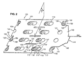
図2に示されるように、相互接続システム100は、実質的に長方形の薄い板101の形をとる。
As shown in FIG. 2, the
図2において、われわれは、相互接続システム100に沿って置かれた中心軸OO’を定義する。
In FIG. 2, we define a central axis OO ′ placed along the
板101は、電子制御サポーター300に近い端部において接続領域140を延長しており、前記接続領域140は、電気端末によって、電子制御サポーター300に接続されるものである。The
この領域140は、板101の幅よりも小さな幅の長方形領域141によって形成され、この長方形領域141は、軸OO’から垂直に遠ざかるにつれて板101の方に近寄る領域142によって延長されている。この領域142は、電気終端を受け入れるように設計された幅の長方形領域143で終わっている。
This
相互接続システム100がケーシング201に取り付けられるために、接続領域140は、監視手段300を含むケーシング201の側面203にこの目的のために設けられたスロット202の中に滑り込み、サポーター300に接続されるために側面203の上に平に配置されている。(図1参照)
In order for the
したがって、ケーシング201の上面204の上に平に配置された板101と接続領域140は、監視手段300に近い端部102に存在する肘形部の2つの直角を成す部分を形成している。
Therefore, the
さらに、本発明の一態様に従って、相互接続システム100は、エネルギー蓄積セルの極性端子500の上に相互接続システム100を保持するための手段110、120および150を形成する或る数の切抜きと、エネルギー蓄積組立品200の加熱板400を受け入れるための取付け部品130とを含む。
Further in accordance with one aspect of the present invention, the
極性端子500の上にシステム100を保持するための手段110、120および150を形成する切抜きは、選択的なやり方で配置され、極性端子500がエネルギー蓄積組立品200のケーシング201の上面204から相互接続システム100の外の外部に突き出ることができるようにする。
The cutouts forming the means 110, 120 and 150 for holding the
本発明の好ましい実施形態では、これらの切抜きの特質は、それが監視手段に近い端部102に位置しているか、その反対側の端部104に位置しているか、相互接続システム100の中央領域105に位置しているかに従って異なる。
In a preferred embodiment of the present invention, these cut-out attributes are either located at the
しかし一般に、保持手段110、120および150用に意図された全ての切抜きに関して、これらの切抜きの各々の間の軸OO’に沿った距離およびこの軸に対して垂直な距離は、個々のエネルギー蓄積セルの極性端子500間の距離およびセルの幅にそれぞれ対応している。
In general, however, for all cuts intended for the holding means 110, 120 and 150, the distance along and perpendicular to the axis OO ′ between each of these cuts is the individual energy storage. This corresponds to the distance between the
さらに、切抜きの列は軸OO’の方向およびこの軸に垂直な方向に整列されており、これは組立品200のケーシング201中のエネルギー蓄積セルの整列に対応している。
Furthermore, the row of cutouts is aligned in the direction of axis OO 'and in the direction perpendicular to this axis, which corresponds to the alignment of the energy storage cells in the
さらに、切抜きは、中心軸OO’に関して対称に構成されている。 Furthermore, the cutout is configured symmetrically with respect to the central axis OO '.
より正確には、相互接続システム100の端部から離れて存在する保持手段110は、中心垂直面(B)と中心軸OO’の交点(A)に関して対称であり、保持手段110はこの面(B)のどちらの側にも位置している。
More precisely, the holding means 110 existing away from the end of the
本発明の好ましい実施形態に従って、保持手段は、長方形の切抜き110の形をとり、その切抜き110の2つの相対する辺118、118’は凸状円弧の形であり、他の2つ119、119’は、相互接続システム100に沿って等しく、かつ平行な直線である。
According to a preferred embodiment of the invention, the holding means takes the form of a rectangular cut-out 110, the two
この切抜き110は、それの長さの中心で、2つの異なるセルの2つの極性端子500に対応するように意図された2つの部分111と117に分けられる。
This cut-out 110 is divided in its center in length into two parts 111 and 117 intended to correspond to two
これらの部分の1つ117は何も無いが、他方の部分111は、接続用アイレット115によって延長された接続ジャンパ112を含む。
One of these parts 117 is empty, while the other part 111 includes a connection jumper 112 extended by a
このジャンパ112は肘の形をとり、その肘形部分のうちの一方113は中心軸OO’に対して垂直で、切抜き110の長さの中間で相互接続支持物101に接続されており、他方の部分114は、肘形ジャンパ112の内角の方に開いた開き角116を有する円弧115の形をして辺118に向かって延長されている。
This jumper 112 takes the form of an elbow, one of which 113 is perpendicular to the central axis OO 'and is connected to the
さらに、監視手段300から離れた端部104に、2つの型の切抜き150および155が、板101の幅にわたって交互に位置している。より正確には、軸OO’の一方の側に2つの切抜き150が位置し、一方で、他方の側では、軸OO’の近くに位置する切抜き155に続いて、外の方に切抜き150がある。
In addition, at the
板101の外部の方に開いた円弧154の形をした第1の型の切抜き150は、中心軸OO’に対して垂直で、かつ相互接続支持物101の端部104で相互接続支持物101に接続された直線接続ジャンパ151を含む。
A first mold cut 150 in the form of an
切抜き150の何も無いスペースに面した開き角153を有する円弧の形をしたアイレット152によって、ジャンパ151は延ばされている。
The
第2の型の切抜き155は、相互接続板101の外部の方に開いた何も無い円弧156である。
The
監視手段に近い端部102では、接続領域140の近くに、2つの型の切抜き120および121が、また、交互に位置している。より正確には、一対の切抜き120および121が軸OO’の各側に位置し、切抜き121が軸OO’に近く配置されている。
At the
第1の型の切抜き120は、反対側の端部104と同じようにジャンパ122および相互接続アイレット123を含み、唯一の差は、本質的にこの側で板101が狭いために、監視手段300に近い端部102でジャンパ122がより短いことである。
The first mold cutout 120 includes a
第2の切抜き121は、円形のものである。
The
有利なことには、異なる切抜き110、120および150の接続ジャンパの特定の形は、相互接続システム100の回路の伝導トラックに対応するように意図された板101の面積の上に、できるだけ重なり合わないで最大限の長さを得るように選ばれた。
Advantageously, the particular shape of the connection jumpers of the different cut-outs 110, 120 and 150 overlap as much as possible over the area of the
さらに、ジャンパの長さは、意図された極性端子500に面するアイレット115の開口を生じさせるために、ねじってジャンパを変形させることを可能にするが、このことは図3、4および5に関連して後で説明される。
In addition, the length of the jumper allows the jumper to be twisted and deformed to produce an opening in the
さらに、中心軸OO’に関する切抜きの、より詳細には接続ジャンパの全体的な対称性は、ジャンパが発生する力の観点から相互接続支持物101の釣り合いを可能にする。実際に、ジャンパの弾性作用のために、ジャンパは、それが接続されることになる極性端子500から相互接続アイレット115、123および152を遠ざける傾向がある。
Furthermore, the cut-out with respect to the central axis OO ', more particularly the overall symmetry of the connection jumper, allows the
有利なやり方では、システム100の端から遠く離れて存在する保持手段110のアイレット115は、相互接続システム100の縁部に位置するアイレット152および123のものと同じ長さである肘形ジャンパ112を有しているが、一方では、依然としてセルの端子500の通り抜けのために切り抜かれた板101の何も無い部分117を越えないし、さらに端子500の通り抜けを妨げない。アイレットの全体的な向きはシステム100の中心軸に関して対称になっている。
In an advantageous manner, the
さらに、相互接続システム100は、エネルギー蓄積組立品200の加熱板400の収容取付け部品130を含む。
In addition, the
収容取付け部品130は、複数の細い長方形の切抜き131の形をとり、この切抜きの2つの相対する辺132および133は凸状円弧の形であり、他の2つ131および135は、相互接続システム100に沿って等しくかつ平行な直線である。収容取付け部品130は、好ましくは、相互接続システム100の中心領域105の中心軸OO’に対して平行に配置される。
The receiving
保持手段110、120および150および収容取付け部品130の多種多様な構成は、セルの極性端子500に機械的電気的に接続するというそれらの役割を最適化するために、しかしまた、相互接続システム100の伝導回路に専用のスペースまたは再びシステム100の製造条件を最適化するために、相互接続支持物101の表面に設計されてもよい。
The wide variety of configurations of the retaining means 110, 120 and 150 and the
さらに、切抜きの数、面積、形状、特質、および向きは、多くの実施変形物の主題である。これらは、添付の図に特定の例示に限定されない。 Further, the number, area, shape, nature, and orientation of the cutouts are the subject of many implementation variations. These are not limited to specific illustrations in the attached figures.
相互接続支持物100を組立品200のエネルギー蓄積セルの極性端子500と組み立てることは、これから、図3、4および5に関連して説明される。
Assembling the
図3に表された個々のセルの極性端子500は、円柱513の形をとり、この円柱513の役割は、電気化学素子が配置されたセルの内部から外部への電気伝導を実現することである。図に示されたこの円柱513は、実際は、相互接続支持物101に対して垂直に配置された極性端子500の主軸513である。
The
この円柱513は、より大きな直径の2つの環状肩部510および515によって広げられ、下の肩部515は円柱513の下端部に存在し、上の肩部510は円柱513の上端部に存在している。
The
これらの肩部の内側面512および518によって、これらの肩部は、環状チャネル520のブランチを形成している。
With these shoulder
さらに、円柱513の下端部では、下の肩部515は、同軸の正方形プレス加工部514をそれの内面518の上に載せており、この正方形プレス加工部514は、極性端子500をセルの上に固定するために使用される。
Further, at the lower end of the
このプレス加工部514は、半径方向で外側に向かって動くにつれて下の肩部515の方に近寄る表面で形成された面取り部517によって終わっている。この面取り部517はクランプ・ツールが極性端子500をしっかり掴むのを容易にするために使用される。
This
下の肩部515は、また、外側の面519がより小さな直径の第2の同軸円柱516によって延長され、この第2の同軸円柱516は、エネルギー蓄積セル(図に示されない)の中に存在する電気化学素子との直接電気接続の役割をする。
The
図3に示されているように監視手段300から最も遠く離れた端部104に位置する切抜き150を考えよう。相互接続アイレット152は、2つの肩部510および515によって形成されたチャネル520の中に横から滑り込む。
Consider a cutout 150 located at the
より正確には、アイレット152の上面157が、極性端子500の上の肩部510の下部分512に接触することできるようにするために、アイレット152の開き角153は、前述のチャネル520のレベルで軸513のまわりに相補的なやり方で係合する。
More precisely, in order to allow the
アイレット152の開き角153は、軸513の定められた位置にアイレット152を捕らえるように設計されている。
The
しかし、極性端子500の上の肩部510の下部分511と相互接続支持物101の相互接続アイレット152の上面157との間には高さの差がある。
However, there is a height difference between the
これらを互いに接触させるために、高さの差は、ねじることによって変形する相互接続ジャンパ151によって補償される。ジャンパ151の長さは、依然としてアイレット152を極性端子500に位置合わせすることを可能にしながら、アイレット152と支持物101の高さの差を処理するために使用される。
In order to bring them into contact with each other, the height difference is compensated by an
さらに、セルの極性端子500によって相互接続システム100に接続されたセルは、互いに接続され、より正確には、図1に示されるように直列に接続される。
Further, the cells connected to the
電気化学セルを電気的に接続するために使用される電力接続システムの例が、図4および5に示されている。 An example of a power connection system used to electrically connect electrochemical cells is shown in FIGS.
このシステムは一対の電気化学セルの2つの極性端子500を直列に接続するために、電気伝導部品540ならびに2つのバネ素子550を含む。
The system includes an electrically
図4に示されるように、個々のセルの極性端子500は、実質的に長方形の母線540によって、隣接したセル(図示されない)の極性端子500に連結される。
As shown in FIG. 4, the
母線540の一方の端部543は、上の肩部510の上面511上に、極性端子500の軸513に対して垂直に、平に位置付けされる。
One end 543 of the
この端部543に、母線540は、極性端子500の軸513の中心に来るように位置決めされた正方形の切抜き541を有し、この正方形の切抜き541は、まず第1に極性端子500と母線540の間の接触、次に極性端子500とアイレット152の間の接触を生じさせるバネ素子550を取り付けるための位置決め点として作用する。
At this end 543, the
正方形の切抜き541の両側に、この母線540は、また、母線540の各長手方向側面にあるU字状チャネル542、544をこの端部543に含んでいる。これらのチャネル・ブランチは、母線の幅よりも小さい幅の肩部545の存在によって形成され、母線540の幅と同一の幅の第2の肩部546によって延長されている。
On either side of the
相対するチャネル542、544の長さは、同一であり、極性端子500の直径に実質的に対応している。
The lengths of the
これらのチャネル542、544は、極性端子500と母線540の間の接触子の役割をする部品(図に示されていない)が母線540上に固着することができるようにする。
These
この母線540は、好ましくは薄い銅で作られる。
The
バネ素子550は、クリップ550で構成される。このクリップ550は、軸513に対して垂直に横から滑ることによって、相互接続アイレット152、極性端子500の上の肩部510、接触部品および母線540で構成されたスタックを確実に接触させ、この組立品に固着する。このクリップ550は、U字状断面の部品の形をとり、この部品の2つの上部551および下部552ブランチは、それぞれ、母線540の上面と、および上の肩部510の下面512に接触した相互接続アイレット152と、組み立てられるように設計されている。
The
バネ素子550の下部ブランチ552は、その長さにわたって、2つの同一の腕金553、554に分割され、この分割は、クリップ550の中間部分で軸513に対して垂直に延びている。
The
2つの下部腕金553、554は、相互接続アイレット152の下面158と接触し、上部ブランチ551は、母線540の上面と接触する。
The two
図5に示されるように、アイレット152は、クリップ550の下部腕金553および554によって、端子500の上の肩部510の内面512に接触した状態にさせられる。
As shown in FIG. 5, the
さらに、バネ素子550は、それの上部ブランチ551に、正方形の固着ラグ555を含み、このラグ555は、取付け部品に対するデバイス550の適正な位置付けを示すために使用される。滑り動作中に、このラグ555は、母線540の正方形に切抜き541の中に滑り込み、エネルギー蓄積組立品200によって経験される機械応力によってクリップ550が極性端子500から外れるのを防止するために使用される。
In addition, the
バネ素子550は、連続した圧縮力をエネルギー蓄積セルに加えるために使用される。
The
エネルギー蓄積セル間の電力接続システムの特質は、多くの実施変形物の主題であることがある。電力接続システムは、前述の図3、4および5で特定の例示に限定されてはならない。 The nature of the power connection system between energy storage cells may be the subject of many implementation variants. The power connection system should not be limited to the specific illustration in FIGS. 3, 4 and 5 described above.
図6および7は、相互接続システム100の板101の導電領域に形成された伝導プリント回路800の電気図を与え、このプリント回路800は、エネルギー蓄積組立品200を、それの健全状態を監視する手段300に接続するために使用される。
6 and 7 provide an electrical diagram of a conductive printed
本発明に従って、相互接続支持物101は、導電材料のシートがその上に堆積された絶縁基板を含む。
In accordance with the present invention, the
このシートは、それ自体は知られているやり方で、相互接続システム100の伝導回路800の電気トラックを実現するように処理される。
This sheet is processed in a manner known per se to realize an electrical track of the
支持物101は、好ましくは、ポリエステル型の絶縁基板上のアルミニウムの薄いシートで構成されている。
The
絶縁基板の特質および伝導シートの特質は多くの実施変形物の主題であることがある。
特に、伝導領域は、銅のシートで構成されてもよい。
The nature of the insulating substrate and the nature of the conductive sheet can be the subject of many implementation variants.
In particular, the conductive region may be composed of a copper sheet.
さらに、本発明に従って、相互接続システム100は可撓性である。このことにより、前述の図に示されるように、保持手段110、120および150の接続ジャンパをねじることおよび相互接続システム100の3次元の構成が可能になる。
Further, in accordance with the present invention, the
ここで図6を参照すると、一組のn個のエネルギー蓄積セルが直列に接続されて示されている。 Referring now to FIG. 6, a set of n energy storage cells are shown connected in series.
本発明に従って、各セル1からnは、回路10からn0にそれぞれ接続されており、回路10からn0は、個々のセルのエネルギー状態を示すオン/オフ切り換えを含んだ電圧測定回路、および、このエネルギー状態に依存したオン/オフ切り換えを含んだ各セルを通過する電流の分流回路、を意図するように構成されている。
In accordance with the present invention, each
個々のエネルギー蓄積セル2に関して、分流回路20は、セル2に並列に接続されている。導体21は、セル2の極性端子2aから始まる電流分流回路を形成し、エネルギー蓄積組立品200の監視手段300につながり、エネルギー蓄積組立品200の中でオン/オフ切り換え手段23に接続されている。
For each energy storage cell 2, the
このオン/オフ切り換え手段23は、また、セル2の他方の極性端子2bに至る電流戻り経路を形成する第2のトラック22に接続されている。 The on / off switching means 23 is also connected to a second track 22 that forms a current return path to the other polarity terminal 2 b of the cell 2.
オン/オフ切り換え手段23は、好ましくは、スイッチである。 The on / off switching means 23 is preferably a switch.
オン/オフ切り換え手段13からn3の存在によって、各分流回路10からn0は、その他のセルに接続されたその他の回路に無関係に動作することができるようになる。
The presence of the on / off switching means 13 to n3 allows each of the
有利なやり方では、オン/オフ切り換え手段13からn3は、測定されるべきセルと、測定されるべきセルに隣接した2つのセルのうちの少なくとも1つとを電気的に分離するように設計されている。 In an advantageous manner, the on / off switching means 13 to n3 are designed to electrically isolate the cell to be measured and at least one of the two cells adjacent to the cell to be measured. Yes.
好ましいやり方では、オン/オフ切り換え手段13からn3は測定されるべきセルと、測定されるべきセルに隣接した2つのセルの各々とを電気的に分離するように設計されている。 In a preferred manner, the on / off switching means 13 to n3 are designed to electrically isolate the cell to be measured and each of the two cells adjacent to the cell to be measured.
したがって、各分流回路n0の全てまたは一部は、対応するセルの測定回路として使用され、また逆に、セルの測定回路は、隣接したセルの分流回路n0の全てまたは一部を使用する。このことは、支持物101上に存在する導体の数を限定し、かつ存在する導体の線引きおよび形状を合理化するために使用される。
Therefore, all or part of each shunt circuit n0 is used as the corresponding cell measurement circuit, and conversely, the cell measurement circuit uses all or part of the shunt circuit n0 of the adjacent cell. This is used to limit the number of conductors present on the
さらに、本発明に従って、各電流分流回路n0は、電流制限器の役割をする少なくとも電気抵抗性かつ熱伝導性の素子Rnを含む。 Furthermore, in accordance with the present invention, each current shunt circuit n0 includes at least an electrically resistive and thermally conductive element Rn that acts as a current limiter.
この素子Rnは、好ましくは、エネルギー散逸抵抗である。 This element Rn is preferably an energy dissipation resistor.
したがって、図6を参照すると、分流回路20のオン/オフ切り換え手段23は、伝導状態と非伝導状態の間で変化し、伝導状態であるとき、対応するエネルギー蓄積セル2を流れる電流の一部を組立品200の損失抵抗にそらす。
Therefore, referring to FIG. 6, the on / off switching means 23 of the
本発明の好ましい実施形態に従って、相互接続支持物101の伝導領域に構成されるべき導体の数を制限するために、分流回路10からn0の経路設定は、電気抵抗性で熱伝導性の素子Rnをエネルギー蓄積セルの正極性端子と後続のエネルギー蓄積セルの負端子に交互に接続するように決定される。
In order to limit the number of conductors to be configured in the conductive region of the
このことは、また、分流回路10からn0の第2のトラック(電流戻りトラック)12からn2にも適用される。
This also applies to the second track (current return track) 12 to n2 of the
さらに、各セル1からnが組立品200のその他のセルと直列に接続され、さらに相互接続支持物101に接続されている場合、ある電圧レベルが生成され、エネルギー蓄積組立品200の健全状態を監視する手段300によって測定されることがある。
In addition, when each
本発明の一態様に従って、組立品200のエネルギー蓄積セル1からnの各々の電圧測定回路は、伝導回路800に集積化される。
In accordance with one aspect of the present invention, the voltage measurement circuit for each of the
本発明の好ましい実施形態では、これらの電圧測定回路は、前述の分流回路10からn0と同一である。
In a preferred embodiment of the invention, these voltage measurement circuits are identical to the
しかし、分流回路10からn0のうちのいくらかは、それらが既に行われた測定と重複する測定を与えることが分ったとき、電圧測定に使用されない。したがって、全てのエネルギー蓄積セルの監視を達成するために監視手段300の測定回路の数を減らすことができる。
However, some of the n0 from
例えば、図6を参照すると、エネルギー蓄積セル1に関して、分流回路10を形成する伝導トラック11および12は、この特定のセル1の測定経路V1を形成する伝導トラックに対応する。
For example, referring to FIG. 6, for the
蓄積セル2に関して、この特定のセル2の測定経路は、トラック11および22に対応する。
With respect to the storage cell 2, the measurement path of this particular cell 2 corresponds to the
電位検出線11および22は、セル2の両側で、組立品200の健全状態を監視する手段300に存在する電圧検出回路に延びている。
The
ある特定の精度で電圧の測定を行うために、非伝導状態に関係した分流回路20を制御するオン/オフ切り換え手段23だけでなく、V2の測定回路と共通の導体(11および22)を有する隣接した分流回路を活動化する手段(13および33)も配置することが必要である。
In order to measure the voltage with a certain accuracy, it has not only the on / off switching means 23 for controlling the
同様に、セル3の測定を行うために、トラック(22および31)の全電流を阻止し、したがって活動化手段23および43を非伝導状態に置くことが必要であろう。
Similarly, in order to make a measurement of
分流回路を非伝導状態に置くことは、その目的として、電流の通過によって伝導トラックに生じる電圧降下に対処することを有し、この電圧降下は、測定されるべき電圧値に追加され、測定をゆがめるかもしれない。 Placing the shunt circuit in a non-conducting state has, as its purpose, dealing with the voltage drop that occurs in the conducting track due to the passage of current, this voltage drop being added to the voltage value to be measured and making the measurement May be distorted.
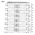
本発明に従った相互接続システム100のために構成された電気回路800の異なる電位測定線の例が、12個のエネルギー蓄積セルの組立品200について、図7に表されている。
An example of different potential measurement lines of an
線Vn+およびVn−は、エネルギー蓄積セルの正極性端子500および負極性端子500のレベルで測定された電位をそれぞれ表す。
Lines Vn + and Vn− represent potentials measured at the level of the
さらに、線CPC1からCPC12は、エネルギー蓄積セル1から12の電力損失抵抗を含んだ伝導トラックのレベルで測定された電位をそれぞれ表す。
Further, lines CPC1 through CPC12 represent the potentials measured at the level of the conduction track including the power loss resistance of
好ましくは、電圧測定を行うために、スイッチ13からn3は、個々のエネルギー蓄積セルの各対のトラック(Vn、CPCn)の間にケーブル配線される。 Preferably, switches 13 to n3 are cabled between each pair of tracks (Vn, CPCn) of individual energy storage cells to make voltage measurements.
相互接続支持物101の導電領域は、図6および7に関連した前述の伝導プリント回路800を与えるために処理される。
The conductive areas of the
有利なことには、伝導プリント回路800とエネルギー蓄積セルの極性端子500との間の電気接触は、半田付け/溶接、蝋付けまたは接着によって、それ自体は知られているやり方で生成される。
Advantageously, the electrical contact between the conductive printed
より正確には、図3に示されるような個々の極性端子500に関して、蝋付け、半田付けまたは接着された接触は、伝導回路800の一部をその露出した表面領域157に現す切抜き150の相互接続アイレット152に、極性端子500の上の肩部510の内面512を接触させることによって実現される。
More precisely, with respect to individual
本発明の好ましい実施形態に従って、各分流/測定回路10からn0の伝導トラックはセルの極性端子500を受け入れるように意図された各切抜き110、120および150から、長手方向に相互接続支持物101の長さに沿って、監視手段300に近い端部102まで延びるように構成されている。
In accordance with a preferred embodiment of the present invention, each shunt /
この端部102で、これらの伝導トラックは、必要な経路の数を含む電気終端に接続され、この電気終端それ自体は知られている。
At this
この電気終端は、好ましくは、相互接続支持物101に圧着または半田付けされるコネクタ930である。
This electrical termination is preferably a
このコネクタ930は、伝導プリント回路800を、ステープル型の接触子を含む接続領域940を介して監視手段300の接続ソケットに接続する。
This
さらに、有利なことには、ただ1つの同じ相互接続アイレットは、互いに接続された隣接したセルの端子から来る、または始まるトラック全てを接続するために使用され、したがって、同じ電位の点を生成する。 Furthermore, advantageously, only one identical interconnect eyelet is used to connect all tracks that come from or start at the terminals of adjacent cells connected to each other, thus producing the same potential point. .
さらに、電気抵抗性で熱伝導性の電流制限素子Rnの存在によって決定される伝導トラックは、定められた抵抗を持たなければならない。 Furthermore, the conduction track, which is determined by the presence of an electrically resistive and thermally conductive current limiting element Rn, must have a defined resistance.
このために、伝導トラックを経路設定する規則に従って、われわれは、われわれが求める抵抗率に適したトラック長/幅の対を選ぶ。 To this end, according to the rules for routing conductive tracks, we choose track length / width pairs that are suitable for the resistivity we seek.
本発明の他の態様に従って、電力損失抵抗Rnは、伝導回路800の電流トラック、より正確には各セル10からn0の測定分流回路の電流トラックで構成され、前記の抵抗Rnの値は、バイパスされるべきセルの端子と監視されるべきシステム300の間の対応するトラックの経路設定抵抗で構成される。
In accordance with another aspect of the present invention, the power loss resistor Rn consists of the current track of the
各セルに関連した一定断面の電力損失抵抗Rnの長さは、相互接続システム100に対するセルの位置付けがどうであろうとも、全て同一であるように選ばれる。
The length of the constant loss power loss resistor Rn associated with each cell is chosen to be the same regardless of the positioning of the cell relative to the
抵抗素子R1からRnを伝導回路800の中に集積化することは、相互接続システム100の支持物101での熱の放散を引き起こす。
The integration of the resistive elements R1 to Rn into the
本発明の一態様に従って、過度に高い表面エネルギー密度を回避し、かつエネルギー蓄積組立品200の温度一様性の釣り合いを過度に失わせないために、抵抗性トラックのレイアウトは、相互接続支持物101の全面積に適切に広がるように最適化される。
In accordance with one aspect of the present invention, in order to avoid an excessively high surface energy density and not to lose excessively the temperature uniformity balance of the
さらに、各抵抗の熱放散を相互接続システム100の全てにわたって分散させるため、トラックの経路設定断面はトラックの長さ全てにわたって一定であるように選ばれる。
Further, in order to dissipate the heat dissipation of each resistor throughout the
さらに、バイパスされるセル以外の全てのセルで散逸されるエネルギーを最適に分散させるために、あるセルに関連する損失抵抗R1からRnは、隣接したセルの手前で最大に延びる。 Furthermore, the loss resistances R1 to Rn associated with a cell extend to the maximum before the adjacent cells in order to optimally dissipate the energy dissipated in all cells except the bypassed cell.
エネルギー蓄積セルによるこれらの構成によってリカバリーつまり正常な状態とされたエネルギーは、エネルギー蓄積組立品200の温度の維持に寄与する。したがって、有利なことには、組立品200の温度調節用の加熱板で消費されるエネルギーは減少する。
The energy that is recovered, that is, the normal state by these configurations of the energy storage cell, contributes to the maintenance of the temperature of the
また、明記されることであるが、第2のトラック(戻りトラック)は、監視されるべきシステム300の働きによって固定される閾値よりも小さな最大値を持たなければならないので、各戻りトラックの抵抗の値を最小限にするために、前記の戻りトラックは、相互接続支持物101の寸法を考慮に入れて、できるだけ大きな断面で、かつ接続されたセルの端子と監視されるべきシステム300の間でできるだけ短く、かつできるだけ真っ直ぐな経路で作られる。
It is also noted that the second track (return track) must have a maximum value that is less than a threshold that is fixed by the operation of the
最後に、本発明の好ましい実施形態に従って、相互接続システム100は、また、熱結合を最適化するために、セルの最上部にある厚さの弾性材料を押し付けて接着または保持される。
Finally, in accordance with a preferred embodiment of the present invention, the
この材料は、好ましくは、エラストマまたは多孔性のものである。 This material is preferably elastomeric or porous.
本発明の一実施変形物は、相互接続支持物101の伝導領域が導体の幅と長さの間の妥協を実現するのに十分でない場合、伝導トラックの断面に関して最良の妥協を得るため、伝導領域の厚さを増すか減らすことを提案する。
One implementation variant of the present invention provides the best compromise with respect to the cross-section of the conduction track if the conduction region of the
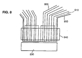
本発明の他の態様に従って、相互接続システム100は、また、伝導プリント回路800を電磁干渉から保護するための遮壁910を含む。
In accordance with another aspect of the present invention, the
本発明に従って、この遮壁910は、図8に示されるように、絶縁層900によって伝導プリント回路800から隔てられた伝導材料層である。
In accordance with the present invention, the
好ましい実施変形物では、遮蔽層910は、保持手段110、120および150、および伝導回路800を電子制御サポーター300に接続するための領域940を除いて、相互接続支持物100の全体を覆うことがある。
In a preferred implementation variant, the
図7に戻ると、この遮壁層は、電位Vssであり、監視手段300に近い端部102の近くで、コネクタ930によって監視手段300の接地面に電気的に接続されている。
Returning to FIG. 7, this barrier layer is at the potential Vss and is electrically connected to the ground plane of the monitoring means 300 by the
本発明の実施変形物は、両面構造またはそれどころか多層構造である相互接続支持物101を示す相互接続システム100に関する。
An implementation variant of the invention relates to an
多層相互接続支持物101の限定しない例は、各々がそれぞれ伝導抵抗性トラック、遮壁および第2のトラック(電流戻りトラック)を含むように構成された3つの伝導層を有するかもしれない。
A non-limiting example of
層の配列、特質、数は、多くの実施変形物の主題である。特に、人は、エネルギー蓄積組立品200の加熱抵抗用の電力供給を行う余分な層を追加することに言及するかもしれない。
The arrangement, nature and number of layers are the subject of many implementation variants. In particular, one may mention adding an extra layer that provides power for the heating resistance of the
他の実施変形物は、電子部品、より詳細にはCMS型の部品を取り付けるために意図された領域が相互接続支持物上に存在することを提案する。 Another implementation variant proposes that there is an area on the interconnect support intended for mounting electronic components, more particularly CMS type components.
本発明に従った相互接続システム100を備えるエネルギー蓄積組立品200の典型的な動作モードでは、直列に接続されかつ相互接続システム100で相互接続されたエネルギー蓄積セルは、エネルギーを消費する素子に与えられる負荷電流を生成する。
In a typical mode of operation of an
正常な条件では、監視手段300によって試験される分流回路10からn0の各々は、接続されたセルを流れる電流の通過を妨害しないように非活動状態のままである。
Under normal conditions, each of the
定められた設定値レベルに達した特定のエネルギー蓄積セルnの電圧の測定に応じて、このセルnに専用の分流回路n0はオンに切り換えられ、負荷電流は、欠陥のあるセルnを、それの電圧が下がるまでバイパスして、その他のエネルギー蓄積セルを通って伝導される。この分流は、相互接続システム100の全面積にわたってエネルギーを散逸する。
In response to the measurement of the voltage of a particular energy storage cell n that has reached a defined setpoint level, the shunt circuit n0 dedicated to this cell n is switched on and the load current causes the defective cell n to Will be conducted through other energy storage cells, bypassing until the voltage decreases. This shunt dissipates energy over the entire area of the
当業者は、最新技術の知られたデバイスに関連して、どんな高エネルギー電池技術にも簡単で、確実で、かつ効率のよいやり方で使用することができる相互接続システムの長所を認めるであろう。限定しない例として、リチウムポリマー技術、ニッケル金属水素化物技術、または、確かにリチウムイオン技術に言及することができる。 Those skilled in the art will appreciate the advantages of an interconnect system that can be used in any high energy battery technology in a simple, reliable and efficient manner in connection with known devices in the state of the art. . As non-limiting examples, mention may be made of lithium polymer technology, nickel metal hydride technology, or indeed lithium ion technology.
さらに、本発明に従った相互接続システム100は、依然として正確な電気接続を提案しながら、このシステム100がその構成を意図されたエネルギー蓄積組立品200に適応させることできるようにする可撓性を含む。
Furthermore, the
最後に、本発明に従った相互接続システム100は、まず第1に欠陥のあるセルの存在した状態で電流の効率のよい分流を可能にし、かつ次にエネルギー蓄積組立品200の温度調節を改善する非一体型電力損失抵抗R1からRnを有するという有利点を提供する。
Finally, the
もちろん、本発明は、つい今しがた説明されたばかりの特定の実施方法に限定されず、本発明の精神に合致するどんな変形物にも及ぶ。特に、本発明は、添付の図面に限定されない。先行する段落で例示された特定の参照は、本発明の限定しない例である。 Of course, the present invention is not limited to the particular implementation just described, but extends to any variant that meets the spirit of the present invention. In particular, the present invention is not limited to the attached drawings. The specific references illustrated in the preceding paragraphs are non-limiting examples of the invention.
Claims (12)
前記各蓄電セル(1,2,・・・,n)はそれぞれの最上部に一対の極性端子(500)を有し、
前記相互接続支持物(101)は可撓性であって、基板の表面に形成された伝導回路(800)を有し、前記相互接続支持物(101)には前記極性端子(500)を保持しない箇所(117,121)と、前記極性端子(500)を機械的に保持する保持手段を有する箇所(111,120,150)とが形成されており、
前記複数の蓄電セル(1,2,・・・,n)の順次直列接続は、隣り合う2つの蓄電セルの極性の異なる前記極性端子(500)を互いに接続するための導電性接続部品(540)およびバネ素子(550)によって行われており、
また、前記極性端子(500)は、いずれも、前記相互接続支持物(101)における前記極性端子(500)を保持しない箇所(117,121)、または、前記極性端子(500)を機械的に保持する前記保持手段を有する箇所(111,120,150)に、貫通状態で設けられており、
前記保持手段が前記極性端子(500)を機械的に保持することによって、前記極性端子(500)と前記電子制御サポーター(300)とが前記伝導回路(800)を介して電気的に接続されており、
前記伝導回路(800)は、前記各蓄電セル(1,2,・・・,n)のエネルギー状態である電圧を示す前記電圧測定回路を備え、前記各蓄電セル(1,2,・・・,n)の各々が電圧測定回路と接続可能とされており、
さらに、前記伝導回路(800)は複数の電流分流回路(10,20,・・・,n×10)を備え、各電流分流回路(10,20,・・・,n×10)は、前記各蓄電セル(1,2,・・・,n)の前記一対の極性端子(500)に接続されて、前記各蓄電セル(1,2,・・・,n)のバイパス回路として機能するものとして構成されており、前記各電流分流回路(10,20,・・・,n×10)は、前記各蓄電セル(1,2,・・・,n)のエネルギー状態に依存したオン、オフの切り換えをする、スイッチ(13,23,33,・・・)を有し、
さらに前記各電流分流回路(10,20,・・・,n×10)は、電流制限素子(R1,…,Rn)を含んで設計されており、
前記複数の電流分流回路のうち電気的に両端にある2つの前記電流分流回路(10、n×10)を除いた前記複数の電流分流回路(20,30,・・・,n×10−10)においては、電気的に隣り合う2つずつの前記蓄電セル((20,30)(40,50)・・・)がペアを作っており、前記ペアの各々において、前記ペアにおける2つの前記蓄電セルがそれぞれ、第1の蓄電セル及び第2の蓄電セルをなし、前記第1の蓄電セルに接続された前記電流分流回路が第1の電流分流回路をなし、前記第2の蓄電セルに接続された前記電流分流回路が第2の電流分流回路をなし、前記第1の電流分流回路における前記スイッチが第1のスイッチをなし、前記第2の電流分流回路における前記スイッチが第2のスイッチをなしており、
前記第1の電流分流回路における、前記第1のスイッチの一端と、前記第1及び第2の蓄電セルの接続中点と、を結ぶ第1の配線が、前記第2の電流分流回路における、前記第2のスイッチの一端と、前記接続中点と、を結ぶ第2の配線と同一の配線を共用している、
システム。 A system in which a plurality of storage cells (1, 2,..., N) and an electronic control supporter (300) are interconnected by an interconnecting support (101) , the plurality of storage cells (1, 2, , N) are sequentially connected in series to form a power storage assembly (200), and the electronic control supporter (300) includes a voltage measurement circuit that indicates a voltage that is an energy state of each power storage cell, and In a system configured to monitor a current shunt circuit including on and off switching depending on this energy state ,
Wherein each storage cell (1, 2, · · ·, n) have each a pair of polarity terminal (500) at the top,
The interconnect support (101) is flexible and has a conductive circuit (800) formed on a surface of a substrate, and the interconnect support (101) holds the polar terminal (500). A portion (117, 121) not to be formed and a portion (111, 120, 150) having a holding means for mechanically holding the polar terminal (500) are formed.
The sequential series connection of the plurality of storage cells (1, 2,..., N) is a conductive connection component (540) for connecting the polar terminals (500) having different polarities between two adjacent storage cells. ) And the spring element (550),
In addition, the polarity terminal (500) mechanically connects the location (117, 121) of the interconnect support (101) that does not hold the polarity terminal (500) or the polarity terminal (500). In the place (111, 120, 150) having the holding means to hold, it is provided in a penetrating state,
The holding means mechanically holds the polarity terminal (500), whereby the polarity terminal (500) and the electronic control supporter (300) are electrically connected via the conduction circuit (800). And
The conduction circuit (800) includes the voltage measuring circuit that indicates a voltage that is an energy state of each of the storage cells (1, 2,..., N) , and each of the storage cells (1, 2,. , N) can be connected to a voltage measuring circuit,
Furthermore, the conduction circuit (800) includes a plurality of current shunt circuits (10, 20,..., N × 10), and each current shunt circuit (10, 20,..., N × 10) Connected to the pair of polarity terminals (500) of each storage cell (1, 2,..., N) and functions as a bypass circuit for each storage cell (1, 2,..., N) Each current shunt circuit (10, 20,..., N × 10) is turned on and off depending on the energy state of each storage cell (1, 2,..., N). Switch (13, 23, 33,...)
Further, each of the current shunt circuits (10, 20,..., N × 10) is designed including current limiting elements (R1,..., Rn),
The plurality of current shunt circuits (20, 30,..., N × 10 −10) excluding the two current shunt circuits (10, n × 10) electrically at both ends of the plurality of current shunt circuits. ), The two electrically adjacent storage cells ((20, 30) (40, 50)...) Form a pair, and in each of the pairs, Each of the storage cells forms a first storage cell and a second storage cell, and the current shunt circuit connected to the first storage cell forms a first current shunt circuit, and the second storage cell The connected current shunt circuit is a second current shunt circuit, the switch in the first current shunt circuit is a first switch, and the switch in the second current shunt circuit is a second switch. And
In the first current shunt circuit, a first wiring connecting one end of the first switch and a connection middle point of the first and second storage cells is in the second current shunt circuit. Sharing the same wiring as the second wiring connecting the one end of the second switch and the connection midpoint;
system.
路は、その他のセルに接続されたその他の回路に無関係に動作するように設計されていることを特徴とする、請求項1記載のシステム。 Each of the current shunt circuits (10, 20, ..., N × 10 ) and the voltage measurement circuit are designed to operate independently of other circuits connected to other cells. The system of claim 1.
Applications Claiming Priority (3)
| Application Number | Priority Date | Filing Date | Title |
|---|---|---|---|
| FR0507527A FR2888669B1 (en) | 2005-07-13 | 2005-07-13 | INTERCONNECTION SYSTEM FOR AN ENERGY STORAGE ASSEMBLY |
| FR0507527 | 2005-07-13 | ||
| PCT/FR2006/001572 WO2007006898A1 (en) | 2005-07-13 | 2006-07-04 | Interconnection system for an energy storage assembly |
Publications (3)
| Publication Number | Publication Date |
|---|---|
| JP2009501413A JP2009501413A (en) | 2009-01-15 |
| JP2009501413A5 JP2009501413A5 (en) | 2012-04-26 |
| JP5666090B2 true JP5666090B2 (en) | 2015-02-12 |
Family
ID=36371029
Family Applications (1)
| Application Number | Title | Priority Date | Filing Date |
|---|---|---|---|
| JP2008520907A Expired - Fee Related JP5666090B2 (en) | 2005-07-13 | 2006-07-04 | Interconnection system for energy storage assemblies |
Country Status (6)
| Country | Link |
|---|---|
| US (1) | US8431260B2 (en) |
| EP (1) | EP1902483B1 (en) |
| JP (1) | JP5666090B2 (en) |
| CA (1) | CA2615035C (en) |
| FR (1) | FR2888669B1 (en) |
| WO (1) | WO2007006898A1 (en) |
Cited By (1)
| Publication number | Priority date | Publication date | Assignee | Title |
|---|---|---|---|---|
| KR20160107058A (en) * | 2015-03-03 | 2016-09-13 | 삼성에스디아이 주식회사 | Flexible rechargeable battery |
Families Citing this family (8)
| Publication number | Priority date | Publication date | Assignee | Title |
|---|---|---|---|---|
| FR2916306B1 (en) * | 2007-05-15 | 2009-07-17 | Batscap Sa | MODULE FOR ELECTRIC ENERGY STORAGE ASSEMBLIES FOR DETECTING THE AGING OF THESE ASSEMBLIES. |
| US20100028761A1 (en) * | 2008-07-30 | 2010-02-04 | C&D Technologies, Inc. | Storage battery terminal having test surface |
| AT515298B1 (en) * | 2014-01-31 | 2015-08-15 | Avl List Gmbh | Connecting element for contacting at least one cell pole of a battery cell |
| CN107068953A (en) * | 2015-12-30 | 2017-08-18 | 昶洧新能源汽车发展有限公司 | Integrated bus bars and battery for electric vehicle battery group are connected |
| US9966586B2 (en) * | 2015-12-30 | 2018-05-08 | Thunder Power New Energy Vehicle Development Company Limited | Integrated busbar and battery connection for electric vehicle battery packs |
| CN105655536A (en) * | 2016-03-18 | 2016-06-08 | 宁德时代新能源科技股份有限公司 | Tab backing plate |
| JP7041842B2 (en) | 2018-03-26 | 2022-03-25 | トヨタ自動車株式会社 | Assembled battery and manufacturing method of assembled battery |
| CN112331983B (en) * | 2019-11-29 | 2021-10-08 | 宁德时代新能源科技股份有限公司 | Battery module, device and failure processing method of failure battery monomer |
Family Cites Families (13)
| Publication number | Priority date | Publication date | Assignee | Title |
|---|---|---|---|---|
| GB359441A (en) * | 1930-07-21 | 1931-10-21 | John William Manley | Improvements in electric batteries |
| CA1035889A (en) * | 1973-10-13 | 1978-08-01 | Tsutomu Watanabe | Flexible adhesive composition and method for utilizing same |
| US4065710A (en) * | 1975-08-25 | 1977-12-27 | Zytka Bernard J | Substitute power supply and battery charger for battery operated apparatus |
| US5223690A (en) * | 1990-11-29 | 1993-06-29 | Alexander Manufacturing Company | Process and apparatus for spot-welding a flexible welding board to a battery cell |
| US5825155A (en) * | 1993-08-09 | 1998-10-20 | Kabushiki Kaisha Toshiba | Battery set structure and charge/ discharge control apparatus for lithium-ion battery |
| JP3272154B2 (en) * | 1994-07-15 | 2002-04-08 | 三洋電機株式会社 | battery pack |
| US5469002A (en) * | 1994-08-31 | 1995-11-21 | Motorola, Inc. | Bi-level current limiting circuit and battery using same |
| JPH10271705A (en) * | 1997-03-28 | 1998-10-09 | Mitsubishi Electric Corp | Power source circuit |
| US5892351A (en) * | 1997-08-29 | 1999-04-06 | Compaq Computer Corporation | DC-isolated converting battery module |
| ATE333207T1 (en) * | 1998-11-09 | 2006-08-15 | Ballard Power Systems | ELECTRICAL CONTACT DEVICE FOR A FUEL CELL |
| DE10002142B4 (en) * | 1999-01-28 | 2004-04-29 | Sanyo Electric Co., Ltd., Moriguchi | Power supply containing rechargeable batteries |
| JP2001068078A (en) * | 1999-06-22 | 2001-03-16 | Hudson Soft Co Ltd | Battery |
| US7183014B2 (en) * | 2002-03-20 | 2007-02-27 | Nec Tokin Corporation | Battery pack |
-
2005
- 2005-07-13 FR FR0507527A patent/FR2888669B1/en not_active Expired - Fee Related
-
2006
- 2006-07-04 EP EP06778759.8A patent/EP1902483B1/en not_active Not-in-force
- 2006-07-04 US US11/988,959 patent/US8431260B2/en not_active Expired - Fee Related
- 2006-07-04 WO PCT/FR2006/001572 patent/WO2007006898A1/en not_active Application Discontinuation
- 2006-07-04 CA CA2615035A patent/CA2615035C/en not_active Expired - Fee Related
- 2006-07-04 JP JP2008520907A patent/JP5666090B2/en not_active Expired - Fee Related
Cited By (2)
| Publication number | Priority date | Publication date | Assignee | Title |
|---|---|---|---|---|
| KR20160107058A (en) * | 2015-03-03 | 2016-09-13 | 삼성에스디아이 주식회사 | Flexible rechargeable battery |
| KR102320437B1 (en) | 2015-03-03 | 2021-11-01 | 삼성에스디아이 주식회사 | Flexible rechargeable battery |
Also Published As
| Publication number | Publication date |
|---|---|
| JP2009501413A (en) | 2009-01-15 |
| WO2007006898A1 (en) | 2007-01-18 |
| CA2615035A1 (en) | 2007-01-18 |
| FR2888669A1 (en) | 2007-01-19 |
| US20090035607A1 (en) | 2009-02-05 |
| EP1902483A1 (en) | 2008-03-26 |
| US8431260B2 (en) | 2013-04-30 |
| FR2888669B1 (en) | 2010-08-20 |
| EP1902483B1 (en) | 2018-08-22 |
| CA2615035C (en) | 2012-01-10 |
Similar Documents
| Publication | Publication Date | Title |
|---|---|---|
| JP5666090B2 (en) | Interconnection system for energy storage assemblies | |
| US20210249736A1 (en) | Bus bars for battery packs | |
| JP2009501413A5 (en) | ||
| US8822051B2 (en) | Protection circuit module including thermistor and secondary battery pack having the same | |
| CN205863332U (en) | Temperature measurement component, electric appliance component, battery bag connect assembly and automobile batteries bag | |
| US20150044511A1 (en) | Battery pack | |
| JP4996802B2 (en) | Battery sensor device | |
| CN111886507B (en) | Integrated current measuring device | |
| KR20180088197A (en) | Battery pack | |
| US11302981B2 (en) | Battery pack | |
| CN102870252B (en) | Thin type battery module and use the battery pack of this module | |
| EP2804284A2 (en) | Battery pack | |
| KR20170101604A (en) | Battery pack | |
| CN112189383A (en) | FPC connection structure and method for connecting to printed circuit board using FPC connection structure | |
| US20160254522A1 (en) | Interconnect for Battery Pack Protection | |
| EP2833432A2 (en) | Battery pack | |
| CN113092835A (en) | Detection connecting line and manufacturing method thereof | |
| WO2018065853A1 (en) | Battery balancing component | |
| KR102645840B1 (en) | Circuit carrier for battery system and battery system | |
| AU2020393921B2 (en) | Semiconductor device, printed circuit board (PCB), and method of interfacing control pin (gate pin) of a power semiconductor device (MOSFET) to a printed circuit board (PCB) in a battery management system (BMS) | |
| US20220399256A1 (en) | Semiconductor device, printed circuit board (pcb), and method of interfacing control pin (gate pin) of a power semiconductor device (mosfet) to a printed circuit board (pcb) in a battery management system (bms) | |
| EP4066317A1 (en) | Semiconductor device, printed circuit board (pcb), and method of interfacing control pin (gate pin) of a power semiconductor device (mosfet) to a printed circuit board (pcb) in a battery management system (bms) |
Legal Events
| Date | Code | Title | Description |
|---|---|---|---|
| A131 | Notification of reasons for refusal |
Free format text: JAPANESE INTERMEDIATE CODE: A131 Effective date: 20111004 |
|
| A601 | Written request for extension of time |
Free format text: JAPANESE INTERMEDIATE CODE: A601 Effective date: 20111228 |
|
| A602 | Written permission of extension of time |
Free format text: JAPANESE INTERMEDIATE CODE: A602 Effective date: 20120111 |
|
| A601 | Written request for extension of time |
Free format text: JAPANESE INTERMEDIATE CODE: A601 Effective date: 20120206 |
|
| A602 | Written permission of extension of time |
Free format text: JAPANESE INTERMEDIATE CODE: A602 Effective date: 20120213 |
|
| A524 | Written submission of copy of amendment under article 19 pct |
Free format text: JAPANESE INTERMEDIATE CODE: A524 Effective date: 20120305 |
|
| A02 | Decision of refusal |
Free format text: JAPANESE INTERMEDIATE CODE: A02 Effective date: 20121221 |
|
| A521 | Request for written amendment filed |
Free format text: JAPANESE INTERMEDIATE CODE: A523 Effective date: 20130422 |
|
| A911 | Transfer to examiner for re-examination before appeal (zenchi) |
Free format text: JAPANESE INTERMEDIATE CODE: A911 Effective date: 20130626 |
|
| A912 | Re-examination (zenchi) completed and case transferred to appeal board |
Free format text: JAPANESE INTERMEDIATE CODE: A912 Effective date: 20130816 |
|
| A601 | Written request for extension of time |
Free format text: JAPANESE INTERMEDIATE CODE: A601 Effective date: 20131127 |
|
| A602 | Written permission of extension of time |
Free format text: JAPANESE INTERMEDIATE CODE: A602 Effective date: 20131202 |
|
| A601 | Written request for extension of time |
Free format text: JAPANESE INTERMEDIATE CODE: A601 Effective date: 20131227 |
|
| A602 | Written permission of extension of time |
Free format text: JAPANESE INTERMEDIATE CODE: A602 Effective date: 20140108 |
|
| A521 | Request for written amendment filed |
Free format text: JAPANESE INTERMEDIATE CODE: A523 Effective date: 20140922 |
|
| A61 | First payment of annual fees (during grant procedure) |
Free format text: JAPANESE INTERMEDIATE CODE: A61 Effective date: 20141210 |
|
| R150 | Certificate of patent or registration of utility model |
Ref document number: 5666090 Country of ref document: JP Free format text: JAPANESE INTERMEDIATE CODE: R150 |
|
| R250 | Receipt of annual fees |
Free format text: JAPANESE INTERMEDIATE CODE: R250 |
|
| R250 | Receipt of annual fees |
Free format text: JAPANESE INTERMEDIATE CODE: R250 |
|
| R250 | Receipt of annual fees |
Free format text: JAPANESE INTERMEDIATE CODE: R250 |
|
| LAPS | Cancellation because of no payment of annual fees |