JP5665470B2 - Image forming apparatus - Google Patents
Image forming apparatus Download PDFInfo
- Publication number
- JP5665470B2 JP5665470B2 JP2010232848A JP2010232848A JP5665470B2 JP 5665470 B2 JP5665470 B2 JP 5665470B2 JP 2010232848 A JP2010232848 A JP 2010232848A JP 2010232848 A JP2010232848 A JP 2010232848A JP 5665470 B2 JP5665470 B2 JP 5665470B2
- Authority
- JP
- Japan
- Prior art keywords
- mounting
- cartridge
- identification
- process cartridge
- image forming
- Prior art date
- Legal status (The legal status is an assumption and is not a legal conclusion. Google has not performed a legal analysis and makes no representation as to the accuracy of the status listed.)
- Active
Links
Images


Description
本発明は、複写機、プリンタ、ファクシミリ等の画像形成装置に関する。 The present invention relates to an image forming apparatus such as a copying machine, a printer, and a facsimile.
従来、複数のプロセスカートリッジを一列に並べたインライン型の画像形成装置がある。この種の画像形成装置に用いる複数のプロセスカートリッジは、それぞれ画像形成装置本体の所定の位置に装着される必要がある。そのため、このプロセスカートリッジは、それぞれ指定された装着位置以外には装着できない構造になっている。また、1つのプロセスカートリッジを用いる単色の画像形成装置においても、装置本体の仕様や型式に対応したプロセスカートリッジのみを装着可能とし、機能の異なるプロセスカートリッジを装着できない構成になっている。 Conventionally, there is an inline type image forming apparatus in which a plurality of process cartridges are arranged in a line. A plurality of process cartridges used in this type of image forming apparatus must be mounted at predetermined positions on the main body of the image forming apparatus. For this reason, the process cartridge has a structure that cannot be mounted at positions other than designated mounting positions. Further, even in a single color image forming apparatus using one process cartridge, only a process cartridge corresponding to the specification or model of the apparatus main body can be mounted, and a process cartridge having a different function cannot be mounted.
そこで、従来からプロセスカートリッジを誤った位置に誤装着することを抑制する多くの構成が提案されている。例えば、プロセスカートリッジの画像形成装置への装着位置に装着キーなどの凹凸形状を設け、収容する現像剤の色毎に装着キーの位置を変えておく方法がある(特許文献1参照)。 Thus, many configurations have been proposed in the past that prevent erroneous mounting of the process cartridge at an incorrect position. For example, there is a method in which an uneven shape such as a mounting key is provided at the mounting position of the process cartridge to the image forming apparatus, and the position of the mounting key is changed for each color of developer to be accommodated (see Patent Document 1).
しかしながら、特許文献1では、ユーザーが誤装着であることを認識しにくく、誤装着であることを認識せずに強引にプロセスカートリッジを挿入すると、装置本体やプロセスカートリッジが変形してしまうおそれがある。これに対し、誤装着の場合に干渉する範囲を大きくして、装置本体やプロセスカートリッジの変形を抑制することもできるが、装置の大型化を招くといった課題がある。
However, in
そこで本発明は、誤装着であることを認識しやすく、装置の大型化を抑制しつつ、装置本体やプロセスカートリッジが変形を抑制できる画像形成装置を提供することを目的とする。 SUMMARY An advantage of some aspects of the invention is that it provides an image forming apparatus that can easily recognize an erroneous mounting and can suppress deformation of the apparatus main body and the process cartridge while suppressing an increase in size of the apparatus.
上記課題を解決するために本発明に係る画像形成装置の代表的な構成は、固有の識別形状のカートリッジ側識別部をそれぞれに備えた複数のカートリッジを着脱可能な画像形成装置において、前記複数のカートリッジを取り外し可能に装着する複数の装着部と、前記複数の装着部にそれぞれに設けられた識別付勢手段であって、前記カートリッジ側識別部との対応によって、前記装着部に適切なカートリッジが装着される場合は、前記適切なカートリッジが前記装着部の装着位置に装着するのを許容し、前記装着部に適切でないカートリッジが装着される場合は、前記適切でないカートリッジを前記装着部へ装着する装着方向と反対方向へと付勢する識別付勢手段と、前記複数の装着部にそれぞれ設けられた、前記カートリッジを前記装着位置へ付勢する位置決め付勢手段と、を有し、前記識別付勢手段は、前記適切でないカートリッジが装着される場合であっても、前記適切なカートリッジが装着を完了する装着位置まで前記適切でないカートリッジの進入を許容し、前記位置決め付勢手段は、前記適切なカートリッジが装着される場合のみ、前記カートリッジを装着位置へと付勢することを特徴とする。 In order to solve the above problems, a typical configuration of an image forming apparatus according to the present invention is an image forming apparatus in which a plurality of cartridges each having a cartridge-side identification unit having a unique identification shape can be attached and detached. A plurality of mounting portions for detachably mounting the cartridge, and identification urging means provided in each of the plurality of mounting portions, and an appropriate cartridge is attached to the mounting portion according to the correspondence with the cartridge side identification portion. When mounting, the appropriate cartridge is allowed to be mounted at the mounting position of the mounting portion, and when an inappropriate cartridge is mounted on the mounting portion, the inappropriate cartridge is mounted on the mounting portion. the mounting direction and the identification biasing means for biasing in the opposite direction, respectively provided in the plurality of mounting portions, the cartridge the mounting position Positioning urging means for urging to the position, and the identification urging means is not suitable until a mounting position at which the appropriate cartridge completes mounting even when the inappropriate cartridge is mounted. The cartridge is allowed to enter, and the positioning biasing means biases the cartridge to the mounting position only when the appropriate cartridge is mounted .
本発明は、誤装着であることを認識しやすく、装置の大型化を抑制しつつ、装置本体やプロセスカートリッジの変形を抑制できる。 According to the present invention, it is easy to recognize that the mounting is wrong, and deformation of the apparatus main body and the process cartridge can be suppressed while suppressing an increase in size of the apparatus.
次に本発明の一実施形態に係る画像形成装置について図面を参照して説明する。なお、ここでは、本発明に関連する画像形成装置の構成を第1参考例及び第2参考例として説明し、次に本発明の実施形態に係る画像形成装置の構成ついて説明する。
[第1参考例]
本発明に係る画像形成装置の第1参考例について、図を用いて説明する。図1は本参考例に係る画像形成装置の構成図である。図1に示すように、本参考例の画像形成装置100は、鉛直方向に並設された像担持体である感光体ドラム1(1a〜1d)を備えている。感光体ドラム1(1a〜1d)は、不図示の駆動手段によって回転駆動される。全ての感光体ドラム1に対向し、接するように循環移動する静電転写ベルト11が配設されている。
Next, an image forming apparatus according to an embodiment of the present invention will be described with reference to the drawings. Here, the configuration of the image forming apparatus related to the present invention will be described as a first reference example and a second reference example, and then the configuration of the image forming apparatus according to the embodiment of the present invention will be described.
[First Reference Example ]
A first reference example of an image forming apparatus according to the present invention will be described with reference to the drawings. FIG. 1 is a configuration diagram of an image forming apparatus according to this reference example . As shown in FIG. 1, an
図2に示すように、感光体ドラム1の周囲には、その回転方向に従って順に、帯電ローラ2、スキャナユニット3(3a〜3d)、現像ユニット4、静電転写装置5、クリーニング装置6が配設される。感光体ドラム1、帯電ローラ2、現像ユニット4、クリーニング装置6は、一体的にカートリッジ化されプロセスカートリッジ7(7a〜7d)を形成している。
As shown in FIG. 2, a
図1、図2に示すように、プロセスカートリッジ7が、画像形成のタイミングに合わせて順次駆動され、その駆動に応じて感光体ドラム1(1a〜1d)が反時計回りに回転駆動される。そして、各々のプロセスカートリッジに対応するスキャナユニット3(3a〜3d)が順次駆動される。この駆動により、感光体ドラム1表面に対し、帯電ローラ2が一様な電荷を付与し、スキャナユニット3がレーザービーム30(30a〜30d)を照射して潜像形成を行い、現像ユニット4内の現像ローラ40がトナー像を形成(現像)する。
As shown in FIGS. 1 and 2, the
一方、トナー像の形成と同期して、給送カセット8にセットした記録媒体9が静電転写装置5へと搬送され、転写ローラ12(12a〜12d)に電圧を印加することによって、感光体ドラム1(1a〜1d)上のトナー像が順次記録媒体9に転写される。4色のトナー像の転写を受けた記録媒体9は、定着装置10へと搬送され、定着装置10によって熱および圧力を印加されて、転写されたトナー像が記録媒体9上に定着する。記録媒体9は、その後、画像形成装置100の上面に設けられる排出トレイ13へ排出される。
On the other hand, in synchronization with the formation of the toner image, the
[プロセスカートリッジ7の装置本体への着脱]
図3に示すように、画像形成装置100は、着脱可能な複数のプロセスカートリッジ7を装着する装着部101(101a〜101d)を有している。プロセスカートリッジ7は、各画像プロセスに関連する部材(感光体ドラム1やトナーT、帯電ローラ2、現像ローラ40など)の寿命やトナーTの使用量等を考慮して、ある所定量の画像形成の後は新しいものと交換される。プロセスカートリッジ7の交換の際、画像形成装置100の前カバー14を開ける。そして、画像形成装置100の装着部101(101a〜101d)へ、感光体ドラム1を手前にして感光体ドラム1の軸線方向と直交する方向に抜脱(矢印E方向)および装着(矢印D方向)する。
[Removal of
As illustrated in FIG. 3, the
画像形成装置100には、プロセスカートリッジ7(7a〜7d)の装入口102が設けられている。装入口102の両側面にはプロセスカートリッジ7を正規の位置へ導くための左ガイド110(110a〜110d)および右ガイド120(120a〜120d)が、各プロセスカートリッジ7(7a〜7d)毎に設けられている。
The
図4に示すように、プロセスカートリッジ7の側面には、位置決め突起部71、ボス72が設けられている。突起部71は、感光体ドラム1と同軸上に設けられており、画像形成装置100との位置決めを行う。ボス72は、プロセスカートリッジ7の装入方向の先端側に設けられており、画像形成装置100に対する姿勢を決める。装着部101へプロセスカートリッジ7を装着する際は、ボス72を左ガイド110の溝部111に入れて装入していき、次いで突起部71を左ガイド110に設けられる突き当て面112に載せることで装着を行う。最終的には、装置本体に設けられるねじりコイルバネ(位置決め付勢手段)15により、突起部71を左ガイド110に設けられた突き当て面112、113に突き当てることによりプロセスカートリッジ7の装着完了位置が決められる。
As shown in FIG. 4, a
図5(e)に示すように、ねじりコイルバネ15の固定端156は、左ガイド110の穴117に挿入されて固定されている。バネ15の中央のねじり部158は、左ガイド110に設けられたボス114を回転中心として支持されている。バネ15は、突き当て面112、113側へ付勢力が働くように(矢印P方向にモーメントがかかるように)設けられている。バネ15の支持端157は、装入口102に設けられる溝部103によって支持され、矢印P方向への回動が制限されている。バネ15は、ねじり部158と支持端157との間でくの字状に折り曲げられており、屈曲点よりねじり部158側に位置決め付勢部151を有し、屈曲点より支持端157側に押上げ部152を有している。
As shown in FIG. 5 (e), the
プロセスカートリッジ7の装着時は、まず図5(a)に示すように、突起部71が押上げ部152に当接する。さらにプロセスカートリッジ7を装入すると、図5(b)に示すように、突起部71がバネ15の付勢力に抗してバネ15を矢印R方向に押し上げる。そして、図5(c)に示すように、突起部71が屈曲点を超えて位置決め付勢部151に当接し、装着完了位置へと装着される。装着完了位置においては、図5(d)に示すように、突起部71が位置決め付勢部151によって突当て面112、113に突き当たる方向(矢印P方向)に付勢されることで、プロセスカートリッジ7が装着部101に対して位置決め固定される。支持端157および溝部103の形状は、図5(d)のように突起部71が装着完了位置にある状態で支持端157が溝部103から浮いた状態になるように設定されている。これにより、位置決め付勢部151が突起部71を突当て面112、113に突き当てた状態を維持でき、プロセスカートリッジ7が装着部101に対して位置決め固定される。
When the
[プロセスカートリッジ7の誤装着防止手段]
図6に示すように、プロセスカートリッジ7(7a〜7d)は、識別切欠き(カートリッジ側識別部)73(73a〜73d)を有している。識別切欠き73は、装着方向(矢印D方向)の先端側の面に設けられており、各トナー色固有の識別形状となっている。本参考例では、識別切欠き73(73a〜73d)の位置を感光体ドラム1の軸線方向に異なる位置(各トナー色固有の位置)とすることで、各トナー色固有の識別形状としている。
[Incorrect mounting means for process cartridge 7]
As shown in FIG. 6, the process cartridge 7 (7a to 7d) has an identification notch (cartridge side identification part) 73 (73a to 73d). The identification notch 73 is provided on the surface on the tip side in the mounting direction (arrow D direction), and has an identification shape unique to each toner color. In this reference example , the positions of the identification notches 73 (73a to 73d) are different positions in the axial direction of the photosensitive drum 1 (positions specific to each toner color), so that the identification shape specific to each toner color is obtained.
一方、装着部101(101a〜101d)は、各識別切欠き73(73a〜73d)に対応した各色固有の位置に、識別部(識別付勢手段、装着部側識別部)16(16a〜16d)を有している。識別部16は、圧縮バネ(識別付勢手段)17(17a〜17d)を介して画像形成装置100の支持部18(18a〜18d)に取り付けられている。圧縮バネ17は、プロセスカートリッジ7を装着方向と反対方向(矢印E方向)へ付勢する。
On the other hand, the mounting unit 101 (101a to 101d) has an identification unit (identification biasing means, mounting unit side identification unit) 16 (16a to 16d) at a position unique to each color corresponding to each identification notch 73 (73a to 73d). )have. The identification unit 16 is attached to the support unit 18 (18a to 18d) of the
図6(a)に示すように、プロセスカートリッジ7bを適切な装着部101bに装着すると、識別部16bが識別切欠き73bにはまり込み、圧縮バネ17bは圧縮されない。これと同時に、ねじりコイルバネ15bが位置決め突起部71bを突当て面112b、113bに付勢してカートリッジの装着が完了される。
As shown in FIG. 6A, when the
一方、図6(b)に示すように、プロセスカートリッジ7bを適切でない装着部101aに装着すると、識別部16aがプロセスカートリッジ7bの識別切欠き73bと一致せずに、プロセスカートリッジ7bの先端面74bに当接する。さらに装入すると、圧縮バネ17aの付勢力に抗して先端面74bが識別部16aを押し込みながら、ねじりコイルバネ15aが位置決め突起部71bを突当て面112a、113aに付勢して装着完了位置まで装着される。このとき、圧縮バネ17aの装着入口側(矢印E方向)への付勢力がバネ15aの装着部奥側(矢印D方向)への付勢力を上回るように、圧縮バネが設定されている。この状態でユーザーが装着する力を解除すると、圧縮バネ17aの付勢力により、バネ15aの付勢力に抗してプロセスカートリッジ7bが装着入口方向(矢印E方向)へと押し戻される。
On the other hand, as shown in FIG. 6B, when the
本参考例によれば、図6(b)に示すようなプロセスカートリッジ7a〜7dを異なった装着部101a〜101dに装着した誤装着である場合にも、プロセスカートリッジ7を一度は完全な装着完了位置まで装着することを許容する。このため、ユーザーの強引な装着を招きにくい。また、圧縮バネ17a〜17dの付勢力によりプロセスカートリッジ7a〜7dが装着入口側へと押し戻されるため、誤装着であることを認識しやすい。さらに、誤装着を阻止する部材が弾性部材であるため、仮にユーザーの強引な装着が行われても、装置本体やプロセスカートリッジの破損を招きにくい。
According to this reference example , even when the
なお、本参考例では識別形状として装着方向(矢印D方向)の先端側に識別切欠き73を設けたが、図7に示すように、識別形状として識別突起(カートリッジ側識別部)731を設けても良い。この場合、圧縮バネ(識別付勢手段)171を介して画像形成装置100に取り付けられた板状の識別部(識別付勢手段、装着部側識別部)161(161a〜161d)に、識別突起731(731a〜731d)と対応する位置に貫通孔(装着部側識別部)162(162a〜162d)を設ける。これにより、適切なプロセスカートリッジ7を装着した場合には、識別突起731が貫通孔162に挿入され、圧縮バネ171は圧縮されない。これと同時に、ねじりコイルバネ15が位置決め突起部71を突当て面112、113に付勢してカートリッジの装着が完了される。一方、適切でないプロセスカートリッジ7を装着した場合、識別突起731と識別部161が当接して圧縮バネ171が圧縮される。そして、ユーザーが装着する力を解除すると、圧縮バネ171の付勢力により、バネ15の付勢力に抗してプロセスカートリッジ7が装着入口方向(矢印E方向)へと押し戻される。
In this reference example , an identification notch 73 is provided on the tip side in the mounting direction (arrow D direction) as an identification shape. However, as shown in FIG. 7, an identification protrusion (cartridge side identification portion) 731 is provided as the identification shape. May be. In this case, an identification protrusion is formed on a plate-shaped identification unit (identification urging unit, mounting unit side identification unit) 161 (161a to 161d) attached to the
なお、この誤装着防止手段は単色の電子写真画像形成装置やロータリー型のカラー電子写真画像形成装置など、本参考例に示したインライン型のカラー画像形成装置以外にも、機種や仕様の異なるプロセスカートリッジを識別するために用いることもできる。そして、本参考例のようなインライン型のカラー電子写真画像形成装置においては、次の特有な効果が顕れる。すなわち、複数のプロセスカートリッジが隣接して並ぶ構成においては、誤装着カートリッジは他の適切なプロセスカートリッジに比べて一段飛び出るため、識別付勢手段による誤装着カートリッジの移動量が小さくても、誤装着であることを容易に認識できる。 In addition to this in-line type color image forming apparatus shown in this reference example , such as a monochrome electrophotographic image forming apparatus and a rotary type color electrophotographic image forming apparatus, this erroneous mounting prevention means is a process with different models and specifications. It can also be used to identify the cartridge. In the in-line type color electrophotographic image forming apparatus as in the present reference example , the following unique effects appear. That is, in a configuration in which a plurality of process cartridges are arranged adjacent to each other, the erroneously mounted cartridge protrudes one step compared to other appropriate process cartridges. Can be easily recognized.
また、本参考例では誤装着防止手段を、感光体ドラムを有するプロセスカートリッジの誤装着防止に用いたが、現像装置や、現像剤補給容器など、装置本体に対してユーザーが着脱交換するものであれば、感光体ドラムを含むものに限定されない。 In this reference example , the erroneous mounting prevention means is used to prevent erroneous mounting of the process cartridge having the photosensitive drum. However, the user can attach or detach the developing cartridge or the developer supply container to the apparatus main body. If there is, it is not limited to the one including the photosensitive drum.
[第2参考例]
次に本発明に係る画像形成装置の第2参考例について図を用いて説明する。上記第1参考例と説明の重複する部分については、同一の符号を付して説明を省略する。図9(a)は本参考例にかかるプロセスカートリッジ7の斜視図である。図9(b)は本参考例にかかる左ガイド110の斜視図である。
[Second Reference Example ]
Next, a second reference example of the image forming apparatus according to the present invention will be described with reference to the drawings. The same parts as those in the first reference example are denoted by the same reference numerals and the description thereof is omitted. FIG. 9A is a perspective view of the
図9(a)に示すように、本参考例は、上記第1参考例の識別切欠き73に変えて識別突起(カートリッジ側識別部)75を設け、ねじりコイルバネ15に変えてねじりコイルバネ19を設けたものである。
As shown in FIG. 9A, in this reference example , an identification protrusion (cartridge side identification portion) 75 is provided instead of the identification notch 73 of the first reference example , and the
各識別突起75は、プロセスカートリッジ7の装着方向(矢印D方向)と感光体ドラム1の軸線方向の両方に略直交する矢印F方向において異なる位置(各トナー色固有の位置)とすることで、各トナー色固有の識別形状としている。
Each
図9(b)に示すように、ねじりコイルバネ19は、第1参考例のねじりコイルバネ15と同様に、位置決め付勢部191、押上げ部192および固定端196、支持端197を有している。本参考例では、ねじりコイルバネ19は、さらに各トナー色固有の識別部(識別付勢手段、装着部側識別部)193を有している。識別部193は、押上げ部192と支持端197の間に形成されており、プロセスカートリッジ7の誤装着を防止する。識別部193は、当接部194、曲げ部(通過部)195を有している。曲げ部195は、適切なカートリッジの識別突起75のみを通過させるため、各トナー色固有の位置で、識別突起75と干渉しないように曲げられている。当接部194は、適切でないプロセスカートリッジ7の識別突起75と当接し、適切でないプロセスカートリッジ7の装着を阻止する。
As shown in FIG. 9B, the
図10(a)に示すように、プロセスカートリッジ7aを適切な装着部101aに装着すると、識別突起75aが当接部194aに引っかかることなく、曲げ部195aを通過する。次いで、第1参考例と同様に、位置決め突起部71aがねじりコイルバネ19aの押上げ部192aを押し上げて、装着完了位置まで装着される。
As shown in FIG. 10A, when the
一方、図10(b)、図8(a)に示すように、プロセスカートリッジ7aを適切でない装着部101bに装着しようとすると、位置決め突起部71aが押し上げ部192bに当接する前に、識別突起75aが当接部194bと当接する。さらに、プロセスカートリッジ7aを装入していくと、図8(b)に示すように、ねじりコイルバネ19bの回動では当接部194bと識別突起75aの干渉が解消されない。このため、ねじりコイルバネ19bは当接部194bと押し上げ部192bの連結部198bを中心として支持端197bが押し込まれるように矢印Q方向に弾性的に曲げられる。さらに装入していくと、矢印Q方向の曲げ量が増すと同時に、識別突起75aと当接部194bの当接により、当接部194bも矢印S方向に押し込まれる。これにより、図8(c)に示すように、ねじりコイルバネ19bは押上げ部192bが突起部71aを突き当て面112bに付勢する方向(矢印P方向)に回動する。そして、位置決め突起部71aが押し上げ部192bと当接する。この時点で、ねじりコイルバネ19bがそれ以上変形および回動ができなくなり、プロセスカートリッジ7aの装着が阻止される。このときに装着力を解除すると、ねじりコイルバネ19bの矢印Q方向への弾性的な曲げ変形により、当接部194bが識別突起75aを装着方向入口方向(矢印E方向)へと押し戻す力が発生し、プロセスカートリッジ7aは装着入口方向(矢印E方向)へと移動する。
On the other hand, as shown in FIGS. 10 (b) and 8 (a), if the
なお、識別部193と突起部71の形状や位置を各トナー色固有のものにすることで、プロセスカートリッジ7a〜7dが、それぞれ適切な装着部101a〜101dのみに装着可能となり、全ての誤装着パターンにおいて上述と同じ動作を得ることができる。
In addition, by making the shape and position of the
本参考例においては、ねじりコイルバネ19は適切なプロセスカートリッジ7を位置決めする位置決め付勢手段の役割と、適切でないプロセスカートリッジ7を装着入口側へ付勢する識別付勢手段の役割とを兼ねている。
In this reference example , the
本参考例によれば、誤装着である場合にもプロセスカートリッジ7を一度は装着完了位置付近まで装着することができるため、ユーザーの強引な装着を招きにくい。また、第1参考例においては、誤装着時に、位置決め付勢手段(ねじりコイルバネ15)よりも強い付勢力を有する識別付勢手段(圧縮バネ17)に抗して装着する必要があった。これに対し本参考例では、誤装着時にプロセスカートリッジ7を押し戻す際に、識別付勢手段が位置決め付勢手段に抗する必要がない。従って、識別付勢手段の付勢力を第1参考例に比べて低く設定することができるため、誤装着時にユーザーが装着する装着力や識別付勢手段の周辺の部品への負荷を低減することができる。さらに、位置決め付勢手段と識別付勢手段を同一部品としているため、部品点数を削減することができる。
According to this reference example , the
なお、本参考例ではねじりコイルバネ15を装着口の左側面に設けたが、両側面に設けても良い。この場合、プロセスカートリッジ7を装置に平行に押し戻すことができる。また、両側面のねじりコイルバネ15をそれぞれ別の形状にしても良い。この場合には、プロセスカートリッジ7の識別種類を更に増やすことができる。
In this reference example , the
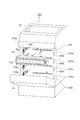
[第1実施形態]
次に本発明に係る画像形成装置の第1実施形態について図を用いて説明する。上記第1参考例と説明の重複する部分については、同一の符号を付して説明を省略する。図11(a)は本実施形態にかかるプロセスカートリッジ7の斜視図である。図11(b)は本実施形態にかかる左ガイド110の斜視図である。
First Embodiment
Next, a first embodiment of an image forming apparatus according to the present invention will be described with reference to the drawings. The same parts as those in the first reference example are denoted by the same reference numerals and the description thereof is omitted. FIG. 11A is a perspective view of the
図11(a)、図11(b)に示すように、本実施形態は、上記第1参考例の識別切欠き73に変えて識別突起(カートリッジ側識別部)76を設け、ねじりコイルバネ15に変えてロック部材20、引っ張りバネ(識別付勢手段)21を設けたものである。
As shown in FIGS. 11A and 11B, in the present embodiment, an identification protrusion (cartridge side identification portion) 76 is provided instead of the identification notch 73 of the first reference example , and the
識別突起76は、プロセスカートリッジ7の側面の位置決め突起部71よりも装着方向(矢印D方向)の下流側に設けられている。各プロセスカートリッジ7の識別突起76は、感光体ドラム1の回転軸と、プロセスカートリッジ7の装着方向(矢印D方向)の両方に略直交する矢印F方向において異なる位置(各トナー色固有の位置)に形成された識別形状となっている。
The
一方、図11(b)に示すように、左ガイド110には、ロック部材20が支持軸116を中心に回動可能に支持されている。引っ張りバネ21は、画像形成装置100に設けられるバネかけ部104とロック部材20の一端との間に設けられている。ロック部材20の他端側には、位置決め付勢部201、押上げ部202が設けられている。ロック部材20の一端は、引っ張りバネ21により引っ張られており、装着完了位置においてロック部材20の位置決め付勢部201が突起部71を突き当て面112、113へ(矢印P方向へ)付勢するようになっている。押上げ部202は、装着時に位置決め突起部71と当接して、引っ張りバネ21の付勢力に抗して矢印R方向に回動する。
On the other hand, as shown in FIG. 11B, the
ロック部材20の一端と支持軸116との間には、識別部203が設けられている。識別部203は、当接部204、切欠き部(通過部)205を有している。切欠き部205は、適切なカートリッジの識別突起76のみを通過させるため、各トナー色固有の位置に設けられている。当接部204は、適切でないプロセスカートリッジ7の識別突起76と当接し、適切でないプロセスカートリッジ7の装着を阻止する。
An
図12および図13(a)に示すように、プロセスカートリッジ7aを適切な装着部101aに装着すると、位置決め突起部71aがロック部材20aの押上げ部202aに当接する。次いで、引っ張りバネ21aの付勢力に抗してロック部材20aを矢印R方向へ回動させ、図13(b)に示すように、ロック部材20aを乗り越える境界点210aまで到達する。このとき、識別突起76aと切欠き205aの位置が一致するため、図13(c)、図13(d)に示すように、識別突起76aは識別部203aを通過して、ロック部材20aが矢印P方向に回動すると共に、位置決め突起部71aが装着完了位置まで装着される。
As shown in FIGS. 12 and 13A, when the
一方、プロセスカートリッジ7aを適切でない装着部101bに装着しようとすると、図14(a)、図14(b)に示すように、位置決め突起部71aがロック部材20bを乗り越える境界点210bまで到達する。このとき、識別突起76aが識別部203bの切欠き205bと一致しないため、プロセスカートリッジ7aをさらに装着すると、図14(c)に示すように、識別突起76aがロック部材20bを矢印R方向にさらに回動させる。そして、図14(d)に示すように、遂には位置決め突起部71aが突き当て面113bに当接し、プロセスカートリッジ7aが一度、装着完了位置まで装着される。ここで装着力を解除すると、引っ張りバネ21の付勢力によりロック部材20bが矢印P方向に回動し、識別突起76aを介してプロセスカートリッジ7aが装着入口方向(矢印E方向)へと押し戻される。このとき、位置決め突起部71aがロック部材20bを乗り越える境界点210bまでは、識別突起76aと当接部204bが当接し続けるため、ロック部材20bは位置決め突起部71aの装着入口方向(矢印E方向)への移動を阻害しない。従って、プロセスカートリッジ7の誤装着である場合は、少なくとも図14(a)の状態までプロセスカートリッジ7aを押し戻すことができる。
On the other hand, if the
なお、識別部203と識別突起76の形状や位置を各トナー色固有のものにすることで、プロセスカートリッジ7a〜7dが、それぞれ適切な装着部101a〜101dのみに装着可能となり、全ての誤装着パターンにおいて上述と同じ動作を得ることができる。
In addition, by making the shape and position of the
本実施形態においては、引っ張りバネ21は適切なプロセスカートリッジを位置決めする位置決め付勢手段の役割と、適切でないプロセスカートリッジを装着入口側へ付勢する識別付勢手段の役割とを兼ねている。
In the present embodiment, the
本実施形態によれば、第1参考例と同様に誤装着時に完全な装着位置まで装着させることと、第2参考例と同様に識別付勢手段の付勢力を低減することが同時に達成される。従って、より強引な装着を招きにくく、かつユーザーの負荷の小さい誤装着防止手段を備えた画像形成装置を提供できる。 According to the present embodiment, as in the first reference example , mounting to a complete mounting position at the time of erroneous mounting and reduction of the biasing force of the identification biasing means are achieved at the same time as in the second reference example. . Accordingly, it is possible to provide an image forming apparatus that is provided with an erroneous mounting prevention unit that is less likely to cause forcible mounting and has a small user load.
T …トナー
1 …感光体ドラム
7 …プロセスカートリッジ
15 …ねじりコイルバネ
16 …識別部(識別付勢手段、装着部側識別部)
17 …圧縮バネ(識別付勢手段)
18 …支持部
19 …ねじりコイルバネ(識別付勢手段、位置決め付勢手段)
20 …ロック部材(識別付勢手段、装着部側識別部、位置決め付勢手段)
21 …引っ張りバネ(識別付勢手段、位置決め付勢手段)
71 …突起部
72、114 …ボス
73 …識別切欠き(カートリッジ側識別部)
731、75、76 …識別突起(カートリッジ側識別部)
74 …先端面
100 …画像形成装置
101 …装着部
102 …装入口
103、111 …溝部
110 …左ガイド
112、113 …突き当て面
120 …右ガイド
156 …固定端
116 …支持軸
117 …穴
151 …位置決め付勢部
157、197 …支持端
158 …ねじり部
161 …識別部(識別付勢手段、装着部側識別部)
162 …貫通孔(装着部側識別部)
171 …圧縮バネ(識別付勢手段)
192、202 …押上げ部
193 …識別部(識別付勢手段、装着部側識別部)
194、204 …当接部
195 …曲げ部
205 …切欠き部
210 …境界点
T ...
17 ... Compression spring (identification biasing means)
18 ...
20: Lock member (identification biasing means, mounting portion side identification portion, positioning biasing means)
21 ... tension spring (identification biasing means, positioning biasing means)
71 ...
731, 75, 76... Identification protrusion (cartridge side identification part)
74 ...
162 ... through hole (mounting part side identification part)
171 ... Compression spring (identification biasing means)
192, 202 ... push-up
194, 204 ... abutting
Claims (4)
前記複数のカートリッジを取り外し可能に装着する複数の装着部と、
前記複数の装着部にそれぞれに設けられた識別付勢手段であって、前記カートリッジ側識別部との対応によって、前記装着部に適切なカートリッジが装着される場合は、前記適切なカートリッジが前記装着部の装着位置に装着するのを許容し、前記装着部に適切でないカートリッジが装着される場合は、前記適切でないカートリッジを前記装着部へ装着する装着方向と反対方向へと付勢する識別付勢手段と、
前記複数の装着部にそれぞれ設けられた、前記カートリッジを前記装着位置へ付勢する位置決め付勢手段と、を有し、
前記識別付勢手段は、前記適切でないカートリッジが装着される場合であっても、前記適切なカートリッジが装着を完了する装着位置まで前記適切でないカートリッジの進入を許容し、
前記位置決め付勢手段は、前記適切なカートリッジが装着される場合のみ、前記カートリッジを装着位置へと付勢すること、を特徴とする画像形成装置。 In an image forming apparatus in which a plurality of cartridges each equipped with a cartridge-side identification portion having a unique identification shape can be attached and detached,
A plurality of mounting portions for removably mounting the plurality of cartridges;
An identification urging unit provided in each of the plurality of mounting units, and when the appropriate cartridge is mounted on the mounting unit due to the correspondence with the cartridge side identification unit, the appropriate cartridge is mounted on the mounting unit. The discriminating bias that allows the cartridge to be mounted at the mounting position and biases the unsuitable cartridge in the direction opposite to the mounting direction in which the non-appropriate cartridge is mounted to the mounting portion. Means,
Positioning biasing means for biasing the cartridge to the mounting position, each provided in the plurality of mounting parts;
The identification biasing means allows the inappropriate cartridge to enter the mounting position where the appropriate cartridge completes mounting even when the inappropriate cartridge is mounted;
The image forming apparatus, wherein the positioning biasing unit biases the cartridge to the mounting position only when the appropriate cartridge is mounted .
前記適切なカートリッジが装着される場合は、前記装着部側識別部は前記カートリッジ側識別部と干渉せず、前記適切でないカートリッジが装着される場合は、前記装着部側識別部が前記カートリッジ側識別部と当接して、前記カートリッジが前記装着部へ装着する装着方向と反対方向へと付勢することを特徴とする請求項1に記載の画像形成装置。 The identification biasing means has a unique mounting portion side identification portion corresponding to the cartridge side identification portion,
When the appropriate cartridge is mounted, the mounting unit side identification unit does not interfere with the cartridge side identification unit, and when the inappropriate cartridge is mounted, the mounting unit side identification unit performs the cartridge side identification. The image forming apparatus according to claim 1, wherein the cartridge is urged in a direction opposite to a mounting direction in which the cartridge is mounted on the mounting portion.
Priority Applications (2)
| Application Number | Priority Date | Filing Date | Title |
|---|---|---|---|
| JP2010232848A JP5665470B2 (en) | 2010-10-15 | 2010-10-15 | Image forming apparatus |
| US13/273,744 US8687984B2 (en) | 2010-10-15 | 2011-10-14 | Image forming apparatus |
Applications Claiming Priority (1)
| Application Number | Priority Date | Filing Date | Title |
|---|---|---|---|
| JP2010232848A JP5665470B2 (en) | 2010-10-15 | 2010-10-15 | Image forming apparatus |
Publications (3)
| Publication Number | Publication Date |
|---|---|
| JP2012088395A JP2012088395A (en) | 2012-05-10 |
| JP2012088395A5 JP2012088395A5 (en) | 2013-10-31 |
| JP5665470B2 true JP5665470B2 (en) | 2015-02-04 |
Family
ID=46260111
Family Applications (1)
| Application Number | Title | Priority Date | Filing Date |
|---|---|---|---|
| JP2010232848A Active JP5665470B2 (en) | 2010-10-15 | 2010-10-15 | Image forming apparatus |
Country Status (1)
| Country | Link |
|---|---|
| JP (1) | JP5665470B2 (en) |
Families Citing this family (7)
| Publication number | Priority date | Publication date | Assignee | Title |
|---|---|---|---|---|
| JP5954949B2 (en) * | 2011-08-30 | 2016-07-20 | キヤノン株式会社 | Developing cartridge and electrophotographic image forming apparatus |
| RU2606343C2 (en) | 2012-09-25 | 2017-01-10 | Кэнон Кабусики Кайся | Image forming device, cartridge and imaging devices system |
| JP2017173421A (en) * | 2016-03-22 | 2017-09-28 | キヤノン株式会社 | Image formation device |
| JP6377209B2 (en) * | 2017-06-07 | 2018-08-22 | キヤノン株式会社 | System for preventing erroneous insertion of cartridge and image forming apparatus |
| EP3674814A3 (en) | 2018-12-28 | 2020-10-21 | Canon Kabushiki Kaisha | Image forming apparatus, and apparatus body thereof |
| JP7171429B2 (en) | 2018-12-28 | 2022-11-15 | キヤノン株式会社 | CARTRIDGE ERROR-INSTALLATION PREVENTION SYSTEM, IMAGE FORMING APPARATUS, AND THEIR APPARATUS |
| JP7229763B2 (en) * | 2018-12-28 | 2023-02-28 | キヤノン株式会社 | Incorrect installation prevention system for cartridges, image forming apparatus |
Family Cites Families (7)
| Publication number | Priority date | Publication date | Assignee | Title |
|---|---|---|---|---|
| JPH0720679Y2 (en) * | 1988-03-01 | 1995-05-15 | 株式会社リコー | Toner supply device and toner cartridge thereof |
| JPH0635320A (en) * | 1992-07-14 | 1994-02-10 | Ricoh Co Ltd | Developing device |
| JPH09146357A (en) * | 1995-11-24 | 1997-06-06 | Mita Ind Co Ltd | Toner cartridge and method and device for preventing erroneous insertion of toner cartridge |
| JPH10254328A (en) * | 1997-03-10 | 1998-09-25 | Canon Inc | Electrophotographic image forming device and process cartridge |
| JP4560699B2 (en) * | 2001-02-15 | 2010-10-13 | ソニー株式会社 | printer |
| JP4632433B2 (en) * | 2005-04-27 | 2011-02-16 | キヤノン株式会社 | Recording device |
| JP5316090B2 (en) * | 2009-03-03 | 2013-10-16 | 株式会社リコー | Cartridge, process cartridge, and image forming apparatus |
-
2010
- 2010-10-15 JP JP2010232848A patent/JP5665470B2/en active Active
Also Published As
| Publication number | Publication date |
|---|---|
| JP2012088395A (en) | 2012-05-10 |
Similar Documents
| Publication | Publication Date | Title |
|---|---|---|
| JP5665470B2 (en) | Image forming apparatus | |
| KR101943020B1 (en) | Process cartridge | |
| EP2102715B1 (en) | Process cartridge and electrophotographic image forming apparatus | |
| JP5004870B2 (en) | Process cartridge and electrophotographic image forming apparatus | |
| US8437661B2 (en) | Process cartridge and electrophotographic image forming apparatus | |
| US8160478B2 (en) | Process cartridge and image forming apparatus | |
| JP2017167522A (en) | Image forming apparatus | |
| JP5067913B2 (en) | Process cartridge and electrophotographic image forming apparatus | |
| JP2007057646A (en) | Photoreceptor cartridge, developing cartridge and image forming apparatus | |
| JP2010210980A (en) | Developing cartridge, process cartridge, and electrophotographic image forming apparatus | |
| JP2013003208A (en) | Image forming apparatus | |
| JP2007183431A (en) | Image forming apparatus | |
| JP6921545B2 (en) | Image forming device | |
| CN109725519B (en) | Image forming apparatus | |
| JP6818833B2 (en) | Process cartridge | |
| JP4569556B2 (en) | Unit attaching / detaching mechanism and image forming apparatus | |
| JP4995243B2 (en) | Developing cartridge, process cartridge, and electrophotographic image forming apparatus | |
| US20220050416A1 (en) | Image forming apparatus |
Legal Events
| Date | Code | Title | Description |
|---|---|---|---|
| A521 | Written amendment |
Free format text: JAPANESE INTERMEDIATE CODE: A523 Effective date: 20130917 |
|
| A621 | Written request for application examination |
Free format text: JAPANESE INTERMEDIATE CODE: A621 Effective date: 20130917 |
|
| A977 | Report on retrieval |
Free format text: JAPANESE INTERMEDIATE CODE: A971007 Effective date: 20140521 |
|
| A131 | Notification of reasons for refusal |
Free format text: JAPANESE INTERMEDIATE CODE: A131 Effective date: 20140527 |
|
| A521 | Written amendment |
Free format text: JAPANESE INTERMEDIATE CODE: A523 Effective date: 20140718 |
|
| TRDD | Decision of grant or rejection written | ||
| A01 | Written decision to grant a patent or to grant a registration (utility model) |
Free format text: JAPANESE INTERMEDIATE CODE: A01 Effective date: 20141111 |
|
| A61 | First payment of annual fees (during grant procedure) |
Free format text: JAPANESE INTERMEDIATE CODE: A61 Effective date: 20141209 |
|
| R151 | Written notification of patent or utility model registration |
Ref document number: 5665470 Country of ref document: JP Free format text: JAPANESE INTERMEDIATE CODE: R151 |