JP5665181B2 - Tear film measurement - Google Patents
Tear film measurement Download PDFInfo
- Publication number
- JP5665181B2 JP5665181B2 JP2010513285A JP2010513285A JP5665181B2 JP 5665181 B2 JP5665181 B2 JP 5665181B2 JP 2010513285 A JP2010513285 A JP 2010513285A JP 2010513285 A JP2010513285 A JP 2010513285A JP 5665181 B2 JP5665181 B2 JP 5665181B2
- Authority
- JP
- Japan
- Prior art keywords
- lipid layer
- tear film
- eye
- light
- illuminator
- Prior art date
- Legal status (The legal status is an assumption and is not a legal conclusion. Google has not performed a legal analysis and makes no representation as to the accuracy of the status listed.)
- Active
Links
- 238000005259 measurement Methods 0.000 title description 15
- 150000002632 lipids Chemical class 0.000 claims description 116
- 238000000034 method Methods 0.000 claims description 26
- 210000001747 pupil Anatomy 0.000 claims description 22
- 230000004397 blinking Effects 0.000 claims description 16
- 238000001228 spectrum Methods 0.000 claims description 16
- 230000001066 destructive effect Effects 0.000 claims description 15
- 238000005286 illumination Methods 0.000 claims description 11
- 238000003384 imaging method Methods 0.000 claims description 11
- 239000006185 dispersion Substances 0.000 claims description 10
- 230000001678 irradiating effect Effects 0.000 claims description 8
- 239000012528 membrane Substances 0.000 claims description 6
- 239000012530 fluid Substances 0.000 claims description 4
- 210000001508 eye Anatomy 0.000 description 66
- 239000010408 film Substances 0.000 description 52
- 208000003556 Dry Eye Syndromes Diseases 0.000 description 10
- 206010013774 Dry eye Diseases 0.000 description 8
- 238000004458 analytical method Methods 0.000 description 7
- 210000004087 cornea Anatomy 0.000 description 4
- 230000000694 effects Effects 0.000 description 4
- 210000000744 eyelid Anatomy 0.000 description 4
- 230000001815 facial effect Effects 0.000 description 4
- 210000001525 retina Anatomy 0.000 description 4
- 238000011282 treatment Methods 0.000 description 4
- 238000001704 evaporation Methods 0.000 description 3
- 230000008020 evaporation Effects 0.000 description 3
- 230000006870 function Effects 0.000 description 3
- 210000003128 head Anatomy 0.000 description 3
- 230000004044 response Effects 0.000 description 3
- 238000010521 absorption reaction Methods 0.000 description 2
- 238000004364 calculation method Methods 0.000 description 2
- 230000001427 coherent effect Effects 0.000 description 2
- 239000003086 colorant Substances 0.000 description 2
- 230000007423 decrease Effects 0.000 description 2
- 208000037265 diseases, disorders, signs and symptoms Diseases 0.000 description 2
- 208000035475 disorder Diseases 0.000 description 2
- 210000001061 forehead Anatomy 0.000 description 2
- 238000010438 heat treatment Methods 0.000 description 2
- 230000006872 improvement Effects 0.000 description 2
- 210000004175 meibomian gland Anatomy 0.000 description 2
- 230000005499 meniscus Effects 0.000 description 2
- 238000012986 modification Methods 0.000 description 2
- 230000004048 modification Effects 0.000 description 2
- 230000003287 optical effect Effects 0.000 description 2
- 230000008569 process Effects 0.000 description 2
- 230000000272 proprioceptive effect Effects 0.000 description 2
- 208000024891 symptom Diseases 0.000 description 2
- 238000012360 testing method Methods 0.000 description 2
- 238000012546 transfer Methods 0.000 description 2
- 239000004925 Acrylic resin Substances 0.000 description 1
- 229920000178 Acrylic resin Polymers 0.000 description 1
- 229910000806 Latten Inorganic materials 0.000 description 1
- 206010052143 Ocular discomfort Diseases 0.000 description 1
- 208000004350 Strabismus Diseases 0.000 description 1
- 230000001133 acceleration Effects 0.000 description 1
- 239000000654 additive Substances 0.000 description 1
- 230000000996 additive effect Effects 0.000 description 1
- 210000003467 cheek Anatomy 0.000 description 1
- 238000006243 chemical reaction Methods 0.000 description 1
- 230000000295 complement effect Effects 0.000 description 1
- 230000006835 compression Effects 0.000 description 1
- 238000007906 compression Methods 0.000 description 1
- 238000001816 cooling Methods 0.000 description 1
- 238000013523 data management Methods 0.000 description 1
- 230000007547 defect Effects 0.000 description 1
- 230000007812 deficiency Effects 0.000 description 1
- 238000009792 diffusion process Methods 0.000 description 1
- 239000003814 drug Substances 0.000 description 1
- 229940079593 drug Drugs 0.000 description 1
- 238000005516 engineering process Methods 0.000 description 1
- 210000002919 epithelial cell Anatomy 0.000 description 1
- 210000000981 epithelium Anatomy 0.000 description 1
- 238000002474 experimental method Methods 0.000 description 1
- 208000030533 eye disease Diseases 0.000 description 1
- 210000004709 eyebrow Anatomy 0.000 description 1
- 238000001727 in vivo Methods 0.000 description 1
- 238000007689 inspection Methods 0.000 description 1
- 230000002452 interceptive effect Effects 0.000 description 1
- 230000001050 lubricating effect Effects 0.000 description 1
- 244000005700 microbiome Species 0.000 description 1
- 239000000203 mixture Substances 0.000 description 1
- 230000003040 nociceptive effect Effects 0.000 description 1
- 210000001331 nose Anatomy 0.000 description 1
- 238000005375 photometry Methods 0.000 description 1
- 230000002028 premature Effects 0.000 description 1
- 230000009023 proprioceptive sensation Effects 0.000 description 1
- 230000001681 protective effect Effects 0.000 description 1
- 238000011002 quantification Methods 0.000 description 1
- 238000001454 recorded image Methods 0.000 description 1
- 230000009467 reduction Effects 0.000 description 1
- 230000011514 reflex Effects 0.000 description 1
- 230000000452 restraining effect Effects 0.000 description 1
- 230000002207 retinal effect Effects 0.000 description 1
- 229920006395 saturated elastomer Polymers 0.000 description 1
- 230000035945 sensitivity Effects 0.000 description 1
- 230000003595 spectral effect Effects 0.000 description 1
- 230000003068 static effect Effects 0.000 description 1
- 230000004488 tear evaporation Effects 0.000 description 1
- 239000010409 thin film Substances 0.000 description 1
- 230000007704 transition Effects 0.000 description 1
- 238000001429 visible spectrum Methods 0.000 description 1
- 238000012800 visualization Methods 0.000 description 1
- 238000009736 wetting Methods 0.000 description 1
Images


Classifications
-
- G—PHYSICS
- G01—MEASURING; TESTING
- G01B—MEASURING LENGTH, THICKNESS OR SIMILAR LINEAR DIMENSIONS; MEASURING ANGLES; MEASURING AREAS; MEASURING IRREGULARITIES OF SURFACES OR CONTOURS
- G01B11/00—Measuring arrangements characterised by the use of optical techniques
- G01B11/02—Measuring arrangements characterised by the use of optical techniques for measuring length, width or thickness
- G01B11/06—Measuring arrangements characterised by the use of optical techniques for measuring length, width or thickness for measuring thickness ; e.g. of sheet material
- G01B11/0616—Measuring arrangements characterised by the use of optical techniques for measuring length, width or thickness for measuring thickness ; e.g. of sheet material of coating
- G01B11/0675—Measuring arrangements characterised by the use of optical techniques for measuring length, width or thickness for measuring thickness ; e.g. of sheet material of coating using interferometry
-
- A—HUMAN NECESSITIES
- A61—MEDICAL OR VETERINARY SCIENCE; HYGIENE
- A61B—DIAGNOSIS; SURGERY; IDENTIFICATION
- A61B3/00—Apparatus for testing the eyes; Instruments for examining the eyes
- A61B3/10—Objective types, i.e. instruments for examining the eyes independent of the patients' perceptions or reactions
- A61B3/101—Objective types, i.e. instruments for examining the eyes independent of the patients' perceptions or reactions for examining the tear film
Landscapes
- Health & Medical Sciences (AREA)
- Life Sciences & Earth Sciences (AREA)
- Physics & Mathematics (AREA)
- Medical Informatics (AREA)
- Surgery (AREA)
- Engineering & Computer Science (AREA)
- Biomedical Technology (AREA)
- Heart & Thoracic Surgery (AREA)
- Biophysics (AREA)
- Molecular Biology (AREA)
- Ophthalmology & Optometry (AREA)
- Animal Behavior & Ethology (AREA)
- General Health & Medical Sciences (AREA)
- Public Health (AREA)
- Veterinary Medicine (AREA)
- General Physics & Mathematics (AREA)
- Eye Examination Apparatus (AREA)
- Length Measuring Devices By Optical Means (AREA)
Description
本発明は一般に、眼の角膜前表面上の涙液層の厚みの測定、より具体的には、涙液層の最外層、すなわち脂質層の厚みの測定の分野に関する。 The present invention relates generally to the field of measuring the thickness of the tear film on the anterior cornea surface of the eye, and more specifically, measuring the thickness of the outermost layer of the tear film, ie, the lipid layer.
ヒトの角膜前涙液層は、3つの主層からなり、それぞれ特定の機能を果たす。角膜前涙液層の最内層は、角膜の表層上皮細胞に保護環境を提供し、微生物および異物に対する保護に役立つ。角膜前涙液層の外面は眼の主屈折面であり、その表面張力はこの表面を滑らかにするのに役立ち、それにより、最終的に網膜に影響を与える像の光学的な質を向上させる。さらに、角膜前涙液層は、まばたき中の潤滑作用を提供する。これらの構造は多くの場合、眼科医により確認される最も一般的な眼疾患の一部である、ドライアイの状態において乱される。ドライアイ疾患および/または病気は、まばたき後に涙液層の早すぎる崩壊をもたらし、これにより表層上皮の損傷をもたらし、結果的に不快感を招き、光のぼけとして現れる場合がある。さらに、患者のコンタクトレンズを装着する能力は、涙液層の質および量に直接的に関係する。したがって、ドライアイ疾患および/または病気は、コンタクトレンズ装着パラメータに大きな影響を有する。 The human precorneal tear layer consists of three main layers, each performing a specific function. The innermost layer of the precorneal tear layer provides a protective environment for the epithelial cells of the cornea and serves to protect against microorganisms and foreign bodies. The outer surface of the precorneal tear layer is the main refractive surface of the eye and its surface tension helps to smooth this surface, thereby improving the optical quality of the image that ultimately affects the retina . In addition, the precorneal tear film provides a lubricating action during blinking. These structures are often disturbed in dry eye conditions, which are some of the most common eye diseases identified by ophthalmologists. Dry eye disease and / or illness may result in premature collapse of the tear film after blinking, thereby resulting in damage to the epithelium, resulting in discomfort and appearing as light blur. Furthermore, the patient's ability to wear contact lenses is directly related to the quality and quantity of the tear film. Thus, dry eye disease and / or illness has a significant impact on contact lens wearing parameters.
角膜前涙液層は、内側のムチン層、中間の液層、および最外側の薄い脂質層から構成される。ドライアイ症状を軽減する試みにおいて、様々な治療法が用いられている。例えば、マイボーム腺の障害を除去するために熱および圧力を加えることにより、またはマイボーム腺の障害を除去するためおよび涙の発生を刺激するために薬物手段を用いて、特定のドライアイ状態を治療することが提案されている。 The precorneal tear layer is composed of an inner mucin layer, an intermediate fluid layer, and an outermost thin lipid layer. Various treatments are used in an attempt to reduce dry eye symptoms. Treat certain dry eye conditions, for example, by applying heat and pressure to remove meibomian gland disorders, or using medicinal means to remove meibomian gland disorders and stimulate tearing It has been proposed to do.
上記にもかかわらず、臨床医および科学者が、提案された治療の結論として、角膜前涙液層の厚みにおける改善を客観的に実証することは、長年にわたり難問題であった。さらに、ドライアイに対する多くの期待が持てる治療法は、機関を満足させるだけの臨床上の有効性を実証できない理由で、米国食品医薬品局からの承認を得ていない。 Despite the above, it has been difficult for many years for clinicians and scientists to objectively demonstrate an improvement in the thickness of the precorneal tear film as a conclusion of the proposed treatment. In addition, many promising treatments for dry eye have not been approved by the US Food and Drug Administration because they cannot demonstrate clinical efficacy to satisfy the agency.
上記の長年にわたる切実な必要性に答えて、角膜前涙液層および具体的にはこの脂質層の厚みを測定する様々な方法が提案されてきた。例えば、本発明の発明者の1人であるKorbは、脂質層の干渉色に基づいて涙液層の脂質層の厚みの定量化を可能にした、鏡面反射顕微鏡システムの発明の概要および背景を提供した。このシステムは、熱吸収フィルタを備える半円筒形の広帯域照射源、高解像度ビデオカメラに70%の光を提供するZeissビームスプリッタを備える双眼顕微鏡、VHSレコーダ、および高解像度約50.8cm(20インチ)のカラーモニタを含んでいた。Eastman Kodak色参照基準(ラッテンフィルタ)を用いる校正後に、まばたき前および後において脂質層の静的および動的な様子が観察された。観察期間中において、被験者は、固視標を見つめる間に自然にまばたきすることを指示された。定量子化および標準化の目的で、分析のために涙液層の特定の領域が指定された。この領域は、下部メニスカスの上方約1mmから下部瞳孔周辺のわずかに下方まで、平均して幅7mmから8mmおよび高さ2.5mmのゾーンを含んでいた。この指定された領域内の鏡面反射光の主色が、脂質層の厚み値を決定するための基本として使用された。厚み値は、涙液層の脂質層に対する干渉色上の以前の作用を基にして、特定の色に対して決定された(McDonald、1969、Nom.、1979、Guilon、1982、Hamanoら、1982)。厚み値は表1にまとめられている。各被験者の涙液層の脂質層について決定された脂質層の厚み値を確認するために、記録結果は、被験者の識別属性に関してはマスキングされた2人の観察者により個別に評価された(Korb、DR、Baron DF、Herman JPら、「Tear Film Lipid Layer Thickness as a Function of Blinking」、Cornea、1994:13:354−9)。上記の装置は、脂質層の厚みの測定の改善には有効であったが、一方で測定の不正確がシステムに生じた。悪い方向に働き、カラーモニタには、脂質層をモニタ画面に画像化できるように十分な入力信号を提供する必要があった。その結果上記は、細隙灯では、その70%が高解像度ビデオカメラに向けられる最低限の照射が提供されることを必要とした。次に、これは、角膜の表面を照射するために要求される最少量の光を要求した。その結果、上述のシステムを作動させるのに必要な光の量は、光により生じる熱が涙液層の蒸発を引き起こすとき、光が自然発生する涙液層を妨げるため、最適ではない。さらに、システムを機能させるのに必要な光の量は、わずかな反射でも涙を生じる原因となった。 In response to the long-standing need described above, various methods have been proposed for measuring the thickness of the precorneal tear layer and specifically the lipid layer. For example, Korb, one of the inventors of the present invention, provides an overview and background of the invention of a specular reflection microscope system that enables quantification of the lipid layer thickness of the tear film based on the interference color of the lipid layer. Provided. The system includes a semi-cylindrical broadband illumination source with a heat absorption filter, a binocular microscope with a Zeiss beam splitter that provides 70% light to a high resolution video camera, a VHS recorder, and a high resolution of about 50.8 cm (20 inches). ) Color monitor. After calibration using the Eastman Kodak color reference standard (Latten filter), a static and dynamic appearance of the lipid layer was observed before and after blinking. During the observation period, subjects were instructed to blink naturally while staring at the fixation target. For the purposes of dequantization and standardization, specific regions of the tear film were designated for analysis. This region contained an average of 7 mm to 8 mm wide and 2.5 mm high zones from about 1 mm above the lower meniscus to slightly below the periphery of the lower pupil. The primary color of the specular light within this designated region was used as the basis for determining the lipid layer thickness value. Thickness values were determined for specific colors based on previous effects on the interference color of the tear film on the lipid layer (McDonald, 1969, Nom., 1979, Guilon, 1982, Hamano et al., 1982). ). The thickness values are summarized in Table 1. To confirm the lipid layer thickness values determined for each subject's tear film lipid layer, the recorded results were evaluated individually by two masked observers for the subject's discriminating attributes (Korb , DR, Baron DF, Herman JP et al., "Tear Film Lipid Layer Thickness as a Function of Blinking", Cornea, 1994: 13: 354-9). While the above device was effective in improving lipid layer thickness measurements, measurement inaccuracies occurred in the system. Working in the wrong direction, the color monitor needed to provide enough input signal so that the lipid layer could be imaged on the monitor screen. As a result, the above required that slit lamps be provided with a minimum of 70% of the illumination directed to the high resolution video camera. This in turn required the minimum amount of light required to illuminate the surface of the cornea. As a result, the amount of light required to operate the system described above is not optimal because when light generated by the light causes the tear film to evaporate, the light interferes with the naturally occurring tear film. In addition, the amount of light required to make the system work caused even a slight reflection to cause tears.
涙液層を測定するための別の装置は、日本の興和株式会社に譲渡された欧州特許出願第0943288号に開示されている。その出願は、下眼まぶたに集まる涙液の量を非接触測定する装置を開示している。この発明によれば、涙の容積は、眼のまぶたのメニスカスに溜まる液の容積を測定して計算される。液の全容積を知ることは、眼科医には多少は有用である場合もあるが、特定の治療計画の結果として、脂質層の厚み測定またはそれの改善を特に測定するものではない。 Another apparatus for measuring tear film is disclosed in European Patent Application No. 094288, assigned to Kowa Co., Ltd., Japan. That application discloses a device for non-contact measurement of the amount of tears that collect in the lower eyelid. According to the present invention, the tear volume is calculated by measuring the volume of fluid that collects in the meniscus of the eyelid. Knowing the total volume of the fluid may be somewhat useful to the ophthalmologist, but is not specifically a measure of lipid layer thickness or improvement thereof as a result of a particular treatment plan.
Marshall G.Doaneの米国特許第4,747,683号では、「Method and Device for in Vivo Wetting Determinations」を開示しており、そこでは、コンタクトレンズがコヒーレント光を用いて照射され、レンズ前の涙液層は、干渉縞を生成するように画像化される。このようにして生成された画像は記録され、涙液層の厚みは、記録された画像の干渉縞の相関を取ることにより決定される。コヒーレント光源およびカメラは、レンズ前の涙液層に焦点を合わせて、涙液層の前面および後面からの鏡面反射光を画像化する。涙液層運動分析器は、干渉縞の数値座標を提供し、マイクロプロセッサは座標値を分析して、レンズ位置または湿潤特性の定量測定を提供する。上記とおなじく、コンタクトレンズの表面を覆う涙液層の厚みを知ることは、コンタクトレンズ装着においては有用であり得るが、Doaneの装置は、自然の眼における脂質層の厚みを特に測定するものではない。 Marshall G.M. Doane's US Pat. No. 4,747,683 discloses “Method and Device for in Vivo Wetting Determinations” in which the contact lens is illuminated using coherent light and the tear film in front of the lens is , Imaged to produce interference fringes. The image generated in this manner is recorded, and the thickness of the tear film is determined by correlating the interference fringes of the recorded image. The coherent light source and camera focus on the tear film in front of the lens and image the specularly reflected light from the front and back surfaces of the tear film. The tear film motion analyzer provides the numerical coordinates of the interference fringes, and the microprocessor analyzes the coordinate values to provide a quantitative measurement of lens position or wetting characteristics. As noted above, knowing the thickness of the tear film covering the surface of the contact lens can be useful in contact lens wear, but the Doane device does not specifically measure the thickness of the lipid layer in the natural eye. Absent.
涙液層の脂質層の厚みを測定することを目的にする別の機器は、Broomall,PAおよびBerkshire,UKのKeeler Instruments Inc.,により製造されているTearscope Plusである。より具体的には、Tearscopeは、同軸に取り付けられた円筒形光源を収容するチューブ状ハウジングを備える、手持ち式または細隙灯取付けデバイスである。ハウジングの内側開口は、光を拡散する円筒形拡散プレートで覆われている。使用するとき、眼科医は、患者の眼の近くにチューブの一端を配置して、瞳孔を含む眼全体を照射し、チューブの反対端を介して瞳孔表面上の干渉縞を観察する。次に、まばたきにより生じる干渉縞の色と涙液層の厚みとの相関関係が求められる。Tearscopeは、眼が照射されるプロセスとして固有の欠点および欠陥がないわけではなく、測定結果には診断上で容認できない誤差が生じる。例えば、可視の干渉縞を観察するために必要な光の強度と相まって、眼の表面に照射器が近いことにより、反射性涙液を生じることがある。さらに、採用される照射システムは、瞳孔を含む眼全体を照射する。したがって、Tearscopeからの光は網膜表面を照射し、これにより固有受容反応を引き起こし、これもまた測定の正確性を損なう。 Another instrument aimed at measuring the lipid layer thickness of the tear film is Broomer, PA and Berkshire, UK, Keeler Instruments Inc. , Tearscope Plus manufactured by. More specifically, the Tearscope is a hand-held or slit lamp mounting device that includes a tubular housing that houses a coaxially mounted cylindrical light source. The inner opening of the housing is covered with a cylindrical diffusion plate that diffuses light. In use, an ophthalmologist places one end of the tube near the patient's eye, illuminates the entire eye, including the pupil, and observes interference fringes on the pupil surface through the opposite end of the tube. Next, the correlation between the color of interference fringes generated by blinking and the thickness of the tear film is determined. Tearscope is not without its inherent drawbacks and defects as a process of irradiating the eye, and the measurement results introduce diagnostically unacceptable errors. For example, coupled with the intensity of light required to observe visible interference fringes, the close proximity of the irradiator to the surface of the eye can produce reflective tears. Furthermore, the irradiation system employed irradiates the entire eye including the pupil. Thus, the light from Tearsscope illuminates the retinal surface, thereby causing a proprioceptive response, which also impairs the accuracy of the measurement.
上記を考慮して、従来技術の欠点および欠陥を克服する方法および装置を提供することが本発明の目的である。 In view of the above, it is an object of the present invention to provide a method and apparatus that overcomes the disadvantages and deficiencies of the prior art.
本発明の別の目的は、角膜前涙液層の脂質層の構成要素の厚みの正確な測定を可能にする方法および装置を提供することである。 Another object of the present invention is to provide a method and apparatus that allows an accurate measurement of the lipid layer component thickness of the precorneal tear film.
本発明の別の目的は、角膜前涙液層の脂質層の厚みが、反射性涙液の発生なく測定され得る方法および装置を提供することである。 Another object of the present invention is to provide a method and apparatus in which the lipid layer thickness of the precorneal tear film can be measured without the generation of reflective tears.
本発明のさらに別の目的は、縮小の程度を大きくし、これにより角膜前涙液層の脂質層の厚みの可観測性および測定可能性を向上する方法および装置を提供することである。 Yet another object of the present invention is to provide a method and apparatus that increases the degree of reduction, thereby improving the observability and measurableness of the lipid layer thickness of the precorneal tear film.
本発明のさらに別の目的は、測定結果を変化させる可能性のある涙液層の蒸発を最小にするために、低レベルの光を使用して角膜前涙液層の脂質層の厚みを測定する方法および装置を提供することである。 Yet another object of the invention is to measure the lipid layer thickness of the precorneal tear film using low levels of light to minimize evaporation of the tear film which may alter the measurement results. A method and apparatus is provided.
本発明の別の目的は、検査中の患者に苦痛を与えない、角膜前涙液層の脂質層の厚みを測定する方法および装置を提供することである。 Another object of the present invention is to provide a method and apparatus for measuring the lipid layer thickness of the precorneal tear layer that does not cause pain to the patient under examination.
本発明の別の目的は、測定結果を変化させる可能性のある、反射性涙液および固有受容反応を最小にするために瞳孔に入る光を最小にする、角膜前涙液層の脂質層の厚みを測定する方法および装置を提供することである。 Another object of the present invention is that of the lipid layer of the precorneal tear layer that minimizes light entering the pupil to minimize reflex tears and proprioceptive responses that can alter the measurement results. It is to provide a method and apparatus for measuring thickness.
上記の点から、本発明は、まばたきに続く脂質層の分散後に、眼の表面上の角膜前涙液層の脂質層の構成要素の厚みを測定する装置を含む。照射器は、患者の眼の脂質層に光を向ける。鏡面反射光線を観察するための手段が備えられる。照射器は、可視領域をカバーする広帯域の広範囲完全拡散光源であり、その光線は、脂質層から鏡面反射され、脂質層内で強め合うおよび弱め合う干渉を受ける。カメラまたは細隙灯といった集光器は、涙液層の脂質層上の干渉縞が観測できるように、鏡面反射光を集光および収束するために提供される。集光器はまた、高解像度ビデオモニタへの投射、あるいはコンピュータによる分析または格納といったさらなる分析に適した、鏡面反射光を表す出力信号を生成する。あるいは、鏡面反射光の干渉縞は、臨床医により直接観察されてもよく、記録されてもよい。測定をより容易にするために、照射器が患者の眼の脂質層に光を向けるとき、患者の頭部は、観察台、例えば細隙灯のスタンド上に置かれてもよい。 In view of the above, the present invention includes an apparatus for measuring the thickness of the lipid layer components of the precorneal tear film on the surface of the eye after dispersion of the lipid layer following blinking. The irradiator directs light to the lipid layer of the patient's eye. Means are provided for observing the specularly reflected light beam. The illuminator is a broadband, fully diffuse light source that covers the visible region, and its rays are specularly reflected from the lipid layer and undergo constructive and destructive interference within the lipid layer. A concentrator, such as a camera or slit lamp, is provided to collect and focus specular light so that interference fringes on the lipid layer of the tear film can be observed. The concentrator also produces an output signal representing the specular light suitable for further analysis, such as projection onto a high resolution video monitor or computer analysis or storage. Alternatively, the specularly reflected interference fringes may be observed directly by the clinician or recorded. To make the measurement easier, the patient's head may be placed on an observation table, such as a slit lamp stand, when the illuminator directs light onto the lipid layer of the patient's eye.
本発明の第1の実施形態では、照射器は、眼全体にわたって脂質層の干渉縞を表すようなサイズとされ、(本明細書では「眼全体の照射器」と称する)、瞳孔に入って網膜に達する光の強度が、検出可能な測定誤差が生じるしきい値を下回る、すなわち反射性涙液および固有受容反応が発生しないようにして実現される。好ましい実施形態における干渉縞の観測は、照射器の開口を通してなされる。 In a first embodiment of the present invention, the illuminator is sized to represent the lipid layer interference fringes throughout the eye (referred to herein as the “entire eye illuminator”) and enters the pupil. This is achieved in such a way that the intensity of light reaching the retina is below the threshold at which a detectable measurement error occurs, i.e. no reflective tears and nociceptive reactions occur. Observation of interference fringes in the preferred embodiment is made through the aperture of the illuminator.
本発明の第2の実施形態では、照射器は、瞳孔の下方に脂質層の干渉縞を表すようなサイズとされ、(本明細書では「眼の半分の照射器」と称する)、これにより瞳孔に入る光の強度が極端に低くなり、したがって、実質的にシステム全体で生じる不正確の発生を回避する。この第2の実施形態における干渉縞の観測は、照射器の上方からである。 In a second embodiment of the invention, the illuminator is sized to represent the interference fringes of the lipid layer below the pupil (referred to herein as the “half-eye irradiator”), thereby The intensity of light entering the pupil is extremely low, thus avoiding inaccuracies that occur substantially throughout the system. The observation of interference fringes in the second embodiment is from above the irradiator.
これらのおよび他の特徴は、図面を参照して理解される。 These and other features are understood with reference to the drawings.
本発明は、特定の実施形態が示されている添付図面を参照して以下により詳細に説明されるが、当業者であれば、本発明の好ましい結果を達成する一方で、本明細書に開示される本発明を変更してもよいことが最初に理解されたい。したがって、以下の説明は、該当技術分野における当業者に向けられた広範な教示の開示であって、本発明についての限定ではないとして理解されたい。 The present invention will be described in more detail below with reference to the accompanying drawings, in which specific embodiments are shown, while those skilled in the art will achieve the preferred results of the present invention while disclosed herein. It should be first understood that the present invention may be modified. Accordingly, the following description is to be understood as a broad teaching disclosure directed to persons of ordinary skill in the relevant arts and not as a limitation on the present invention.
「眼全体の照射器」として本明細書では称される、図1、図2および図6から図8に詳細に図示される第1の実施形態では、本発明による装置は一般に、照射手段100および鏡面反射光を観察するための手段200を備える。「眼の半分の」照射器として本明細書では称される、図3a、図3b、図5aから図5cおよび図9から図11に詳細に図示される第2実施形態が示されている。2つの実施形態の動作モードは実質的に同じであり、同一参照符号を用いて一緒に説明される。ただし、これらの実施形態間に相違が生じる場合は、それらを説明する。 In the first embodiment illustrated in detail in FIGS. 1, 2 and 6 to 8, referred to herein as “entire eye irradiator”, the apparatus according to the invention generally comprises an irradiating means 100. And means 200 for observing specularly reflected light. A second embodiment illustrated in detail in FIGS. 3 a, 3 b, 5 a to 5 c and 9 to 11, referred to herein as a “half-eye” illuminator, is shown. The mode of operation of the two embodiments is substantially the same and will be described together using the same reference numerals. However, when a difference arises between these embodiments, they will be described.
患者の眼の脂質層に光を向けるための照射手段100は、可視領域をカバーし、スタンド300上の眼の前部に配置される完全拡散放射体である、広範囲の広帯域光源を備える。本明細書で採用される用語「完全拡散面」および「完全拡散放射体」は、全方向に等しい強度を有する発光体であると定義される。光源は、放射体から放射される光線が脂質層から鏡面反射され、脂質層において強め合うおよび弱め合う干渉を受けるように配置される、広表面面積放射体を備える。この表面の画像は、その上全体に干渉画像が見られる背景であり、背景は可能な限り空間的に均一でなければならない。照射手段100は、顔の大きい範囲を照射し、脂質層の厚みの決定およびドライアイに対する相関関係に適している、瞳孔310の下方に中心を有する高さ2.5mm、長さ5mmの可視領域を形成する(図12参照)。「可視領域」とは、干渉縞を観察するための基準を満たす、すなわち、眼の半分の照射器については約2.5mm×7mmを満たす、有効領域を意味する。瞳孔領域を除く眼全体の照射は、脂質の分散の眼全体の干渉縞に関する追加情報を明らかにする。
The illumination means 100 for directing light to the lipid layer of the patient's eye comprises a wide range of broadband light sources that are fully diffuse emitters that cover the visible region and are placed in front of the eye on the
照射器100の形態は、カメラレンズから開始し、眼まで前方に、次に照射器まで進むことにより最も容易に理解される。光線の進路を表す基本式はスネルの法則である:
1)N1Sinφ1=N2Sinφ2
ただしNは、光線が通過する媒体の屈折率であり、φは、表面からの垂線に対する光線の角度である。脂質層に入らない反射光線については、N1=N2であり、
2)φ1=φ2
これらの条件においては、スネルの法則は、古典的な「入射角は反射角に等しい」と記述される。
The form of the
1) N 1 Sinφ 1 = N 2 Sinφ 2
Where N is the refractive index of the medium through which the light passes, and φ is the angle of the light with respect to the normal from the surface. For reflected rays that do not enter the lipid layer, N 1 = N 2 and
2) φ 1 = φ 2
Under these conditions, Snell's law is described as the classic “incident angle equals reflection angle”.
本発明によれば、末端部の光線(所望の表示観察領域の最外境界線における光線)のみを決定して、照射器の領域を画定することが必要である。検査される眼のこの領域の部分の表面がほぼ球形であるため、カメラレンズ(または観察者の眼)から、観察される眼の上の観察領域の縁部に引かれる線は、その線と眼との交点における眼の表面に垂直な線の反対側において同一角度で反射する。眼の半分の照射器が使用される場合、照射器は、鼻によりよく適応し、下部の脂質層のより広い領域を照射するように傾斜してもよい。上記にかかわらず、眼の半分の照射器を使用する実験では、10°から30°の傾斜がより有効であることを示した。次に眼全体の照射器に戻ると、図1および図2に最も詳細に示したように、顔の特徴形体が、光線の一部が眼の表面に到達するのを妨害することは明らかである。鼻、頬、眉毛およびまぶたは光線を遮断し、眼の表面に影をもたらす。最大領域を露出するための照射器の位置は、各患者の顔の特徴形体に対して1つだけである。照射器の機械的寸法(高さおよび幅)は、目標母集団の顔の特徴形体の生体測定範囲をカバーするように拡張されてもよい。 According to the present invention, it is necessary to determine only the light rays at the end (light rays at the outermost boundary line of the desired display observation area) to define the area of the irradiator. Because the surface of this area of the eye being examined is nearly spherical, the line drawn from the camera lens (or the observer's eye) to the edge of the observation area above the observed eye is Reflect at the same angle on the opposite side of the line perpendicular to the eye surface at the intersection with the eye. If a half-eye illuminator is used, the illuminator may be better adapted to the nose and tilted to illuminate a wider area of the underlying lipid layer. Regardless of the above, experiments using half-eye illuminators have shown that tilts of 10 ° to 30 ° are more effective. Returning to the whole eye illuminator, it is clear that the facial features obstruct some of the rays from reaching the surface of the eye, as shown in more detail in FIGS. is there. The nose, cheeks, eyebrows and eyelids block the light and cause shadows on the surface of the eye. There is only one position of the illuminator to expose the maximum area for each patient facial feature. The mechanical dimensions (height and width) of the irradiator may be extended to cover the biometric range of facial features of the target population.
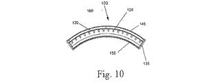
照射手段100は、約400nmから約700nm間の可視領域をカバーする広帯域光源である。作製したモデルでは、前方投影角50°、標準強度2500mcd、および直径5mm(ミシガン州、WixomのNichia Corporationから市販されている部品番号NSPW510CS)を有する、高効率の白色発光ダイオード(LED)120が使用された。本発明に対して他のLEDを加えて、スペクトル幅を近紫外または近赤外域に拡大してもよい。LEDが取り付けられている発光アレイプラットフォーム130(図6、図7)は、眼の光軸から約130°の円弧の範囲にある曲面を有していた(図5a参照)。6つの横列および16の縦列を備える格子パターンで間隔を空けた約96個のLEDは、並列/直列の組み合わせで接続され、適切な電源に接続されているが、当業者には良く知られており、したがって図示されていない。ハウジングは、1組の側方パネル135、底部および上部パネル140、後方パネル145、および拡散手段または拡散器150により、LEDアレイプラットフォーム130のまわりに形成される。それぞれの拡散器150、LEDプラットフォーム130、および後方パネル145は、柔軟であり、上部および底部パネル140ならびに末端片135に配置された溝147内に嵌まり込む。全体のアセンブリは相互にかみ合い、側方パネル135は、次に上部および底部パネル140にねじ止めされる。図示された照射手段100は、曲がっているかまたは弓形であり、検査している眼の中心から半径約19.35cm(7.620インチ)を有するが、眼の周りに130°の範囲を定める限り、平坦であってもよい。曲面は、検査を実行する際により効率的である。この理由は、この形状が、開業医が臨床的な設定において使用することがより容易であるより小さいデバイスを形成するためである。
The
照射器100から放射される全パワーは、涙の蒸発の加速を防止するために最少に維持されなければならない。さらに、加熱または冷却システムにより生成される気流もまた、過剰な蒸発を引き起こすことがあり、測定の正確性を維持するために最小に(好ましくは排除)されなければならない。瞳孔に入るμW/mm2で測定される輝度または強度は、反射性涙液、斜視、および他の視覚の不快性を引き起こすことがあり、これらのすべては測定の正確性に影響を与える。眼全体の照射器に対して、曲線状の完全拡散放射体は、開口160を画定する中心に位置する孔を含み、この開口を通して鏡面反射光を集光および収束するための手段、すなわちカメラ、眼、または他のレンズ200が、位置合わせされる。中心にある開口160は実質的に、直接照射が検査する眼の瞳孔に入るのを防止する。最適ではないが、開口160は、照射器の他の部分に置かれてもよい。しかしながら他方の眼は、瞳孔に入る全光強度を有する。照射強度が十分に低い場合、露出された眼は反応しない。また露出された眼をマスクで遮へいするか、または照射器を分割して表面部分が照射されないようにしてもよい。眼の半分の照射器は、眼の中心線の下方で停止し、どちらの瞳孔も直接照射しないか、またはそうでない場合は、光線が斜めに間接的に瞳孔に入ることだけでき、網膜に当たらない。現在の眼全体の照射器は、約3μW/mm2から15μW/mm2間の輝度または照射強度を有し、照射器の表面において約4.5μW/mm2が好ましく、照射器は眼から約2.54cmから約5.08cm(1から2インチ)に維持される。全放射パワーは1W未満であり、好ましくは400mWを超えない。約6μW/mm2を上回る輝度は、網膜上に直接当たるように瞳孔に入る場合、第2の眼には不快になる。照射器の前面は完全拡散放射体である、すなわち拡大した照射器表面上のすべての点は、完全拡散放射体であり、複数のLED点光源から放射される光を拡散するおよび点光源を均一な完全拡散放射体に変換する機能を果たす、約0.16cm(約1/16インチ)の厚みの柔軟な白色の透光性アクリル樹脂シート150を備える。
The total power emitted from the
固有受容感覚の変化を防止し、涙液層の加熱を低減するために、眼への入射パワーおよび強度を最小にすることが重要であり、したがって、高感度カラーカメラ200などの鏡面反射光を集光および収束するための手段200が採用されなければならない。ビデオカメラ、細隙灯、または他の観察装置200は、開口160に位置合わせされ、また、図2に示すように、スタンド300上に取り付けられるか、または眼の半分の照射器の場合は、図3aおよび図3bのように放射体の上方に位置合わせされる。画像パターンの詳細な視覚化には、脂質層からの干渉縞が観測可能であるように、鏡面反射光を集光および鏡面反射光を収束するための手段を必要とする。優れたディジタル画像化は、脂質の干渉縞が眼の全体にわたって広がっているときに干渉縞の推移を示すために、最大1280×1024ピクセルの解像度および少なくとも15Hzのフレームレートを有する、CCDビデオカメラを必要とする。6.45μm2ピクセルのAVT Dolphin145C、約1.7cm(2/3インチ)CCDカメラは、必要条件に適合し、分析および/または保管する目的に対して、ビデオモニタ(好ましくは高解像度)またはコンピュータといった、多数のデバイスの任意の1つに対する入力信号として役立つことのできるそれらを表す信号を出力する。
In order to prevent changes in proprioceptive sensation and reduce heating of the tear film, it is important to minimize the power and intensity incident on the eye, and thus specular light such as the high
即時涙液層分析器において採用されるレンズシステムは、CCD検出器の有効領域(例えば約1.7cm(2/3インチ)CCDに対して10mmまでの横寸法)上のサンプル平面(眼)に15mmから40mmの寸法を画像化する。レンズのF値は、最大の光を捕集し、優れた画像に必要とされる照射パワーを最小にするためにできるかぎり小さくしなければならない。眼の半分および眼全体の照射システムにおいて選択されるレンズは、約1.7cm(2/3インチ)フォーマットCCDではNavitar Zoom7000の近接フォーカスズームレンズである。より低い倍率において(25mmから40mmの視野)、眼およびまぶたを検査して、脂質層の厚みとまばたきとの関係を観察することができる。脂質層のより詳細な分析は、15mmから25mmの視野を示すわずかに高い倍率を用いて得ることができる。 The lens system employed in the instant tear film analyzer is on the sample plane (eye) on the effective area of the CCD detector (eg, up to 10 mm lateral dimension for a 2/3 inch CCD). Dimension from 15 mm to 40 mm. The F value of the lens should be as small as possible to collect maximum light and minimize the illumination power required for a good image. The lens selected in the half-eye and whole-eye illumination system is a Navitar Zoom 7000 near focus zoom lens for a 2/3 inch format CCD. At lower magnifications (25 mm to 40 mm field of view), the eyes and eyelids can be examined to observe the relationship between lipid layer thickness and blinking. A more detailed analysis of the lipid layer can be obtained using a slightly higher magnification showing a 15 to 25 mm field of view.
脂質層の厚みは均一ではなく、干渉縞に存在する最も支配的な色に基づいて分類される。大多数の個人に対する脂質層は180nmを超えることはなく、厚い脂質層が薄い脂質層に比べて蒸発に対してより優れた保護を提供するため、より厚い脂質層は、ドライアイの状態の拡大に対してより優れた保護を提供すると考えられている。脂質層が薄いほど、特に脂質層の厚みが75nm未満である場合、ドライアイ状態およびドライアイ症状と関連する。 The thickness of the lipid layer is not uniform and is classified based on the most dominant color present in the interference fringes. The thicker lipid layer increases the dry eye condition because the lipid layer for the majority of individuals does not exceed 180 nm and the thick lipid layer provides better protection against evaporation than the thin lipid layer. It is believed to provide better protection against. Thinner lipid layers are associated with dry eye conditions and dry eye symptoms, especially when the lipid layer thickness is less than 75 nm.
本発明のシステムは、脂質層の膜上に入射する白色光からの干渉縞を表示する。干渉縞の色と脂質層の厚み(LLT)との間の関係は表1に示される。

広範囲の調査により、より厚い膜は青および茶色により示され、中間の厚みの膜は黄色により示され、より薄い膜は灰色−黄色により示され、極めて薄い膜は様々な濃度のグレースケールを示し、白色が最も薄いことを表すことが立証された。色測光において、茶色は、小さい強度の赤および緑、またはオレンジおよび青、すなわち基本的に可視光のスペクトルの両端を混合することにより、加法混色において得ることができると考えられる。あるいは、茶色は、白色スペクトルから中心の黄−緑色を除去して、青−オレンジの混色を残すことによって、減色法でも得ることができる。 Extensive studies have shown that thicker films are indicated by blue and brown, intermediate thickness films are indicated by yellow, thinner films are indicated by grey-yellow, and very thin films exhibit varying concentrations of grayscale. It was proved that white represents the thinnest. In color photometry, it is believed that brown can be obtained in additive color mixing by mixing both ends of the spectrum of visible light with low intensity red and green, or orange and blue. Alternatively, brown can also be obtained by subtractive color methods by removing the central yellow-green color from the white spectrum and leaving a blue-orange color mixture.
干渉膜において観察される光の波長が、膜の厚みに逆比例する理由は立証されていないが、広範囲の臨床検査により、本発明者らは、弱め合う干渉が支配的プロセスであるという確信および理論に到達した。波長が膜の厚みに近くなるほど、干渉はより大きくなり、したがって黄−赤干渉は、より厚いフィルムにおいて最大の影響を有する。しかしながら、より厚いフィルムが青を発生し、したがって、赤の波長は、弱め合う干渉により入射光スペクトルから除去され、反射光は青を発生すると想定される。 Although the reason why the wavelength of light observed in the interference film is not inversely proportional to the thickness of the film has not been established, extensive clinical examinations have shown that we have the belief that destructive interference is the dominant process. Reached theory. The closer the wavelength is to the thickness of the film, the greater the interference, so yellow-red interference has the greatest effect on thicker films. However, it is assumed that the thicker film produces blue and therefore the red wavelength is removed from the incident light spectrum by destructive interference and the reflected light produces blue.
より薄い膜については、青はより強い干渉を有する。より薄いフィルムは、赤みを発生するため、青は弱め合う干渉により除去されると仮定される。このことから、本発明者らは、目に見える色は広帯域の表面反射であって、支配的な干渉色の帯域は、除去されていると推定する。すなわち、干渉は、反射光から膜の厚みを示すスペクトルの一部を除去し、補色を残す。これは、茶色がこの種のシステムから得られる理由を、発明者らに理解させる最適な説明である。表1は、可視スペクトルおよびそれぞれの波長の色を一覧表示している。 For thinner films, blue has stronger interference. Since thinner films produce redness, it is assumed that blue is removed by destructive interference. From this, we estimate that the visible color is broadband surface reflection and the dominant interference color band is removed. That is, the interference removes part of the spectrum indicating the thickness of the film from the reflected light, leaving a complementary color. This is the best explanation for the inventors to understand why brown is obtained from this type of system. Table 1 lists the visible spectrum and the color of each wavelength.
眼における脂質層の厚みは、可視光の波長のすべてより大幅に小さいことに留意すべきである。したがって、全波長の干渉縞は不可能であると考えられる。分数波長(λ/2n、n=1、2…)については、干渉縞の強度は、nが増えると急速に減少し、背景から弱い干渉縞を区分する能力は、結果的に低下する。 It should be noted that the lipid layer thickness in the eye is significantly less than all of the wavelengths of visible light. Therefore, interference fringes of all wavelengths are considered impossible. For fractional wavelengths (λ / 2n, n = 1, 2,...), The interference fringe intensity decreases rapidly as n increases, and the ability to distinguish weak interference fringes from the background decreases as a result.
脂質の膜の厚みが約90nm未満になると、本発明の装置(現在のLED光源を採用する)により生成される画像には色が見られず、灰色の濃度だけが変化する。紫および紫外線の干渉の影響が、この厚みにおいて支配的であるが、紫および紫外線は入射スペクトルには存在しないため色を見ることができない、と推定される。可視光スペクトル全体にわたって残る干渉は、極わずかのため(λ/2n、n>5)ため、極めて弱く、このため全スペクトルの反射および吸収の影響が支配的であり、特定の色を見ることができない。60nmから75nm層における広帯域の弱め合う干渉は、最も薄い層(≦30nm)では広帯域の強め合う干渉に取って代わられる。 When the lipid membrane thickness is less than about 90 nm, no color is seen in the image produced by the device of the present invention (which employs current LED light sources), and only the gray density changes. The influence of violet and ultraviolet interference is dominant in this thickness, but it is assumed that violet and ultraviolet are not visible in the incident spectrum, so no color can be seen. The remaining interference over the entire visible light spectrum is very small (λ / 2n, n> 5) and is therefore very weak, so the reflection and absorption effects of the entire spectrum are dominant and certain colors can be seen. Can not. Broadband destructive interference in the 60-75 nm layer is replaced by broadband destructive interference in the thinnest layer (≦ 30 nm).
要約すれば、本発明は、減色法の色の結果を立証するものと考えられ、ここでは、白色光から青色部分を除去すると赤みを帯びた色調が残り、そのスペクトルから中心(黄−緑)を除去すると茶色を帯びた色調が残り、オレンジ−赤を除去すると青色の色調が残る。干渉縞のすべては極わずかな波長であり、したがって強度は相対的に弱く、画像は強く飽和しない。したがって、画像強調技術は、優れた可視性に対してより大きな高い重要性を持つ。約90nm未満の膜の厚みは、グレースケール分析により決定できる。 In summary, the present invention is believed to verify the color results of the subtractive color scheme, where the removal of the blue portion from white light leaves a reddish hue that is centered (yellow-green) from the spectrum. Removing the color leaves a brownish tone, and removing the orange-red color leaves a blue color. All of the interference fringes are very few wavelengths, so the intensity is relatively weak and the image is not strongly saturated. Image enhancement techniques are therefore of greater importance for superior visibility. Film thicknesses less than about 90 nm can be determined by gray scale analysis.
リアルタイムまたは高速データ転送および大容量記憶ボリュームの使用が、所定のアプリケーションに対して要求される場合、高性能コンピュータシステムなどの鏡面反射光を表す出力信号(ビデオ出力信号)を記録する手段に利用が必要とされる。本明細書で採用される用語「リアルタイム」は、観察者が主観的に満足する観察体験に対して要求する、画像生成のために必要な速度でのデータ転送、記憶、および検索として定義される。まばたき後の脂質層の干渉縞運動の観察については、なめらかな運動の認識のためには、最低限毎秒約15フレームで十分である。設定値に応じて、カメラは、毎秒15個の1.4MBから3.9MBの画像を生成でき、または記憶、表示、または計算のために、コンピュータにより21MB/秒から57MB/秒で処理されなければならない。この速度では、1分間の記録は1.26GBから3.42GBの記憶装置を必要とする。現在利用可能な技術であれば、RAMに記録セッションを記憶することは適正ではなく、したがってカメラからのデータは、データの予想量に適合するサイズの記憶システムに直接流れ込まなければならない。例えば、500GBの記憶装置は、1分間の147個から397個の検査結果を記録できる。画像サイズ、圧縮、および優れた診断に適した記録時間を最小にすることを含む、記憶必要条件を低減するために、様々な形式のデータ管理を利用できる。 When real-time or high-speed data transfer and use of a large-capacity storage volume are required for a given application, it can be used as a means for recording an output signal (video output signal) representing specular reflection light such as a high-performance computer system Needed. As used herein, the term “real time” is defined as the data transfer, storage, and retrieval at the rate required for image generation required by the observer for a subjectively satisfied viewing experience. . For observation of the interference fringe motion of the lipid layer after blinking, a minimum of about 15 frames per second is sufficient for smooth motion recognition. Depending on the settings, the camera can generate 15 1.4MB to 3.9MB images per second or be processed by the computer at 21MB / sec to 57MB / sec for storage, display or calculation. I must. At this speed, a one minute recording requires 1.26 GB to 3.42 GB of storage. With currently available technologies, it is not appropriate to store a recording session in RAM, so the data from the camera must flow directly into a storage system sized to fit the expected amount of data. For example, a 500 GB storage device can record 147 to 397 test results per minute. Various forms of data management are available to reduce storage requirements, including minimizing recording time suitable for image size, compression, and good diagnostics.
カメラを操作し、画像を取り込み、画像ファイルを記憶および検索し、データについて選択された計算を実行するためのソフトウェアは、システムを成功に導くには重要である。関連する明細は、
機械システムは、患者の頭部を位置合わせする、照射器およびカメラを位置合わせする、カメラの焦点を合わせる、および眼の間の位置を切り替えるための構成要素からなる。
Software for manipulating the camera, capturing images, storing and retrieving image files, and performing selected calculations on the data is critical to the success of the system. The related items are
The mechanical system consists of components for aligning the patient's head, aligning the illuminator and camera, focusing the camera, and switching the position between the eyes.
現在の眼科医のあご当ては、頭部を位置合わせして、拘束するのに適している。これらは垂直(Z軸)調整を含む。 Current ophthalmologist chin rests are suitable for aligning and restraining the head. These include vertical (Z-axis) adjustment.
可動フレームは、患者の顔の反対側にカメラおよび照射器を配置する。照射器およびカメラは共に大きく動くが、照射器は、異なる顔の形状に対応するために独立したXおよび回転運動を有する。眼から眼への切り替えには、患者の顔から離れてカメラ/照射器のフレーム全体を移動すること(X運動)、および第2の眼と整列するように水平に移動する(Y運動)ことを必要とする。カメラの焦点を合わせることは、X運動の微調整を必要とし、垂直のZ運動は、患者の眼の位置の差に対応するために要求される。従来の細隙灯の生体顕微鏡スタンドは、これらの運動のほとんどを実現し、本発明のシステムでは必要とされない角運動を追加している。 The movable frame places the camera and illuminator on the opposite side of the patient's face. Both the illuminator and camera move greatly, but the illuminator has independent X and rotational movements to accommodate different facial shapes. To switch from eye to eye, move the entire camera / illuminator frame away from the patient's face (X motion) and move horizontally to align with the second eye (Y motion) Need. Focusing the camera requires fine adjustment of the X motion, and vertical Z motion is required to accommodate differences in patient eye position. A conventional slit lamp biomicroscope stand accomplishes most of these movements and adds an angular movement that is not required by the system of the present invention.
図1、図2、図3aから図3cは、眼の全体のシステムを示している。典型的な検査セッションは以下のようである:
事前設定:カメラと照射器との間の垂直関係が設定される。眼の半分の照射器では、カメラの位置は、画像が縁部の影響を含まないように照射器の上部端より十分に高い。眼全体の照射器を使用する場合、カメラは、照射器を通る孔と同軸に位置合わせされる。カメラ/照射器の位置は、以後調整する必要はない。
患者の検査:
1.患者は着席し、あご当てにあごを乗せるように要求される。あご当ては、患者の快適性のために調整される(Z軸)。患者は、前額部当てに前額部を接触させて維持するように要求される。
2.カメラおよび照射器を保持するフレームが、第1の眼の軸上に位置合わせされ、皮膚に大まかに焦点を合わせるために十分近くにまで動かされる。
3.フレームは、垂直および水平の中心合わせのために調整され、次に微調整のために前方に動かされる。
4.照射器は、前後方向に調整され、眼の最適な照射のために回転される。必要に応じて、微調整を繰り返す。患者は、カメラレンズの中心または上部の中心を直接見るように要求される。診断医により、まばたきの仕方に対する指示が患者に与えられる。
5.所望のとおり画像が表示され記録される。
6.フレームが患者から引き離され(鼻を通過して)、次の眼まで水平に移動される。ステップ2から5が繰り返される。
1, 2 and 3a to 3c show the entire system of the eye. A typical test session is as follows:
Preset: The vertical relationship between the camera and the illuminator is set. In the half-eye illuminator, the camera position is sufficiently higher than the upper edge of the illuminator so that the image does not include the effects of the edges. When using a full eye illuminator, the camera is aligned coaxially with the hole through the illuminator. The camera / illuminator position need not be adjusted thereafter.
Patient examination:
1. The patient is required to sit and rest his chin on the chin rest. The chin rest is adjusted for patient comfort (Z axis). The patient is required to keep the forehead in contact with the forehead rest.
2. The frame holding the camera and illuminator is aligned on the first eye axis and moved sufficiently close to focus roughly on the skin.
3. The frame is adjusted for vertical and horizontal centering and then moved forward for fine adjustment.
4). The illuminator is adjusted in the front-rear direction and rotated for optimal illumination of the eye. Repeat the fine adjustment as necessary. The patient is required to look directly at the center or top center of the camera lens. The diagnostician gives the patient instructions on how to blink.
5. Images are displayed and recorded as desired.
6). The frame is pulled away from the patient (through the nose) and moved horizontally to the next eye. Steps 2 to 5 are repeated.
システムは、完全に電動式であり、制御ソフトウェアの高度化に応じて、手動、半自立、または自立モードで作動される。完全な自動化システムは、機械的なスタンドを調整し、カメラの焦点を合わせ、脂質膜の運動を記録し、膜の構造の様々な測定値を計算し、脂質膜の質の評価を報告して、患者の記録ファイルにデータを記録する。 The system is fully motorized and can be operated in manual, semi-autonomous or self-supporting modes depending on the sophistication of the control software. A fully automated system adjusts the mechanical stand, focuses the camera, records the movement of the lipid membrane, calculates various measurements of the membrane structure, and reports an assessment of the quality of the lipid membrane Record data in patient record file.
このように説明してきた本発明は、当業者であれば、装置および方法における種々の変更および変形形態を発案できる。このようなすべての変更および修正は、添付の特許請求の範囲に記載のように、本発明の範囲内であるものとする。 The present invention thus described can be devised by those skilled in the art with various changes and modifications in the apparatus and method. All such changes and modifications are intended to be within the scope of the present invention as set forth in the appended claims.
Claims (15)
患者の眼の涙液層の脂質層に光を向ける照射器を備え、照射器が、完全拡散放射体である可視領域の広帯域スペクトル光源を含み、光源からの光線が、涙液層の脂質層から鏡面反射され、涙液層の脂質層において強め合うおよび弱め合う干渉を受け、さらに、
鏡面反射光を観察する画像化デバイスを備え、涙液層の脂質層上の干渉縞が観察可能であり、また、
照射器により放射された光を拡散するための拡散器を備え、さらに、拡散器が、弓形であり、拡散器から放射された光線が、眼の表面に当たり、スネルの法則が、前記画像化デバイスの受光角に対して満たされ、眼の表面上に干渉の観察可能な領域を形成する、装置。 An apparatus for measuring the lipid layer thickness of the tear film on the surface of the patient's eye after dispersion of the lipid layer of the tear film following blinking,
An irradiator that directs light to the lipid layer of the tear film of the patient's eye, the irradiator comprising a visible-band broadband spectrum light source that is a fully diffusive radiator, and the light from the light source is the lipid layer of the tear film Specularly reflected from and subjected to constructive and destructive interference in the lipid layer of the tear film,
Comprising an imaging device for observing the specular reflection light, Ri interference fringes observable der on the lipid layer of the tear film, also,
A diffuser for diffusing the light emitted by the illuminator, the diffuser being arcuate, the light emitted from the diffuser hitting the surface of the eye, and Snell's law is the imaging device An apparatus that forms an observable region of interference on the surface of the eye that is filled for an acceptance angle of .
可視領域の光を放射するように適合された複数の間隔を空けた発光ダイオードを含む、請求項1に記載の装置。 The irradiator further comprises:
The apparatus of claim 1, comprising a plurality of spaced light emitting diodes adapted to emit light in the visible region.
患者の眼の涙液層の脂質層に光を向ける照射器を備え、照射器が、可視領域の広帯域スペクトル光源であり、かつ完全拡散放射体であり、光源が、涙液層の脂質層から鏡面反射され、涙液層の脂質層において強め合うおよび弱め合う干渉を受け、照射器の表面から放射される全光量が、10μW/mm2未満であり、さらに、
鏡面反射光を観察する画像化デバイスを備え、涙液層の脂質層上の干渉縞が観察可能であり、また、
照射器により放射された光を拡散するための拡散器を備え、さらに、拡散器が、弓形であり、完全拡散放射体から放射された光線が、眼の表面に当たり、スネルの法則が、前記画像化デバイスの受光角に対して満たされ、眼の表面上に干渉の観察可能な領域を形成する、装置。 A device for measuring the lipid layer thickness of the tear film on the surface of the eye after dispersion of the lipid layer of the tear film following blinking,
An irradiator that directs light to the lipid layer of the tear film of the patient's eye, the illuminator being a broadband spectrum light source in the visible region, and a fully diffusing radiator, the light source being from the lipid layer of the tear film The total amount of light emitted from the surface of the irradiator is less than 10 μW / mm 2 that is specularly reflected, subjected to constructive and destructive interference in the lipid layer of the tear film,
Comprising an imaging device for observing the specular reflection light, Ri interference fringes observable der on the lipid layer of the tear film, also,
A diffuser for diffusing the light emitted by the illuminator, and the diffuser is arcuate, the light emitted from the fully diffusing radiator strikes the surface of the eye, Snell's law is the image An apparatus that fills the acceptance angle of the imaging device and forms an observable region of interference on the surface of the eye .
可視領域の光を放射するように適合された複数の間隔を空けた発光ダイオードを含む
、請求項3に記載の装置。 The irradiator further comprises:
4. The apparatus of claim 3, comprising a plurality of spaced light emitting diodes adapted to emit light in the visible region.
患者の眼の涙液層の脂質層に光を向ける照射器を備え、照射器が、可視領域の広帯域スペクトル光源を含み、かつ均一な照射の完全拡散放射体であり、光源が、涙液層の脂質層から鏡面反射され、涙液層の脂質層において強め合うおよび弱め合う干渉を受け、さらに、照射器が、患者の顔を照射するが、瞳孔の下方の領域のみが、スネルの法則を満たし、さらに、
鏡面反射光を観察する画像化デバイスを備え、涙液層の脂質層上の干渉縞が、前記画像化デバイスの受光角に対して瞳孔の下方の領域において観測可能になり、瞳孔の下方の眼に干渉の観察可能な領域を形成し、また、
照射器により放射された光を拡散するための拡散器を備え、さらに、拡散器が、弓形であり、完全拡散放射体から放射された光線が、眼の表面に当たり、スネルの法則が、前記画像化デバイスの受光角に対して満たされ、眼の表面上に干渉の観察可能な領域を形成する、装置。 An apparatus for measuring the lipid layer thickness of the tear film on the surface of the patient's eye after dispersion of the lipid layer of the tear film following blinking,
An irradiator for directing light to a lipid layer of a tear film of a patient's eye, the irradiator comprising a broadband spectrum light source in the visible region and being a uniform diffuse fully diffused radiator, the light source being a tear film Specularly reflected from the lipid layer of the eye and subjected to constructive and destructive interference in the lipid layer of the tear film. Meet, and
Provided with an imaging device for observing specular reflection light, wherein interference fringes on the lipid layer of the tear film can be observed in a region below the pupil with respect to the light-receiving angle of the imaging device, and the eye below the pupil Forms an observable region of interference , and
A diffuser for diffusing the light emitted by the illuminator, and the diffuser is arcuate, the light emitted from the fully diffusing radiator strikes the surface of the eye, Snell's law is the image An apparatus that fills the acceptance angle of the imaging device and forms an observable region of interference on the surface of the eye .
患者の眼の涙液層の脂質層に光を向ける照射器を備え、照射器が、可視領域の広帯域スペクトル光源であり、かつ均一な照射の完全拡散放射体であり、光源が、涙液層の脂質層から鏡面反射され、涙液層の脂質層において強め合うおよび弱め合う干渉を受け、照射器から放射された光が、反射することなく涙液層の脂質層に直接伝搬し、涙液層の脂質層に当たり、さらに、
鏡面反射光を集光および収束する画像化デバイスを備え、涙液層の脂質層上の干渉縞が観察可能であり、また、
照射器により放射された光を拡散するための拡散器を備え、さらに、拡散器が、弓形であり、完全拡散放射体から放射された光線が、眼の表面に当たり、スネルの法則が、前記画像化デバイスの受光角に対して満たされ、眼の表面上に干渉の観察可能な領域を形成する、装置。 A device for measuring the lipid layer thickness of the tear film on the surface of the eye after dispersion of the lipid layer of the tear film following blinking,
An irradiator that directs light to the lipid layer of the tear film of the patient's eye, the irradiator being a broadband spectrum light source in the visible region, and a uniform diffused fully diffused radiator, the light source being the tear film Specularly reflected from the lipid layer of the tear film and subjected to constructive and destructive interference in the lipid layer of the tear film, and the light emitted from the irradiator propagates directly to the lipid layer of the tear film without reflecting, and tear fluid Hits the lipid layer of the layer,
It has an imaging device that collects and converges specularly reflected light, and can observe interference fringes on the lipid layer of the tear film ,
A diffuser for diffusing the light emitted by the illuminator, and the diffuser is arcuate, the light emitted from the fully diffusing radiator strikes the surface of the eye, Snell's law is the image An apparatus that fills the acceptance angle of the imaging device and forms an observable region of interference on the surface of the eye .
患者の眼の涙液層の脂質層を、可視領域にありかつ完全拡散放射体である広帯域スペクトル光源で照射するステップであって、光源からの光線が、涙液層の脂質層から鏡面反射され、涙液層の脂質層において強め合うおよび弱め合う干渉を受けて、干渉縞を生成する、前記照射するステップと、
涙液層の脂質層上の干渉縞が観察可能であるように、鏡面反射光を観察する画像化デバイスのステップと、
照射器により放射された光を拡散する拡散器のステップとを含み、さらに、拡散器が、弓形であり、拡散器から放射された光線が、眼の表面に当たり、スネルの法則が、カメラレンズシステムの受光角に対して満たされ、眼の表面上に干渉の観察可能な領域を形成する、方法。 A method for measuring the lipid layer thickness of a tear film on the surface of a patient's eye after dispersion of the lipid layer of the tear film following blinking,
Irradiating the lipid layer of the tear film of a patient's eye with a broadband spectrum light source that is in the visible region and is a fully diffusive emitter, and the light from the light source is specularly reflected from the lipid layer of the tear film Receiving the constructive and destructive interference in the lipid layer of the tear film to generate interference fringes, the illuminating step;
An imaging device step of observing specular reflection so that interference fringes on the lipid layer of the tear film are observable;
A diffuser step for diffusing the light emitted by the illuminator, wherein the diffuser is arcuate, the light emitted from the diffuser strikes the surface of the eye, Snell's law is the camera lens system A method of forming an observable region of interference on the surface of the eye that is filled for an acceptance angle of .
可視領域の光を放射するように適合された複数の間隔を空けた発光ダイオードを含む、請求項8に記載の方法。 The irradiator further comprises:
9. The method of claim 8, comprising a plurality of spaced light emitting diodes adapted to emit light in the visible region.
患者の眼の涙液層の脂質層を、可視領域にありかつ完全拡散放射体である広帯域スペクトル光源で照射するステップであり、光源が、涙液層の脂質層から鏡面反射され、涙液層の脂質層において強め合うおよび弱め合う干渉を受けて、涙液層に干渉縞を生成し、さらに、照射器の表面から放射される全光量が10μW/mm2未満である、前記照射するステップと、
鏡面反射光を観察するステップと、
照射器により放射された光を拡散するステップとを含み、さらに、照射器が、弓形であり、完全拡散放射体から放射された光線が、眼の表面に当たり、スネルの法則が、カメラレンズシステムの受光角に対して満たされ、眼に干渉の観察可能な領域を形成する、方法。 A method of measuring the thickness of the lipid layer of the tear film on the surface of the eye after dispersion of the lipid layer of the tear film following blinking,
Irradiating the lipid layer of the tear film of a patient's eye with a broadband spectrum light source that is in the visible region and is a fully diffusive radiator, the light source being specularly reflected from the lipid layer of the tear film, Receiving the constructive and destructive interference in the lipid layer of the membrane to produce interference fringes in the tear film, and further irradiating the total amount of light emitted from the surface of the illuminator being less than 10 μW / mm 2 ; ,
Observing specular reflected light; and
Diffusing the light emitted by the illuminator, and the illuminator is arcuate, the light emitted from the fully diffusing radiator strikes the surface of the eye, and Snell's law A method of forming an observable region of interference in the eye that is filled for the acceptance angle .
患者の眼の涙液層の脂質層を、可視領域にありかつ均一な照射の完全拡散放射体である広帯域スペクトル光源照射器で照射するステップであり、光源が、涙液層の脂質層から鏡面反射され、涙液層の脂質層において強め合うおよび弱め合う干渉を受け、照射器が患者の顔を照明するが、瞳孔の下方の領域のみがスネルの法則を満たす、前記照射するステップと、
瞳孔の下方の涙液層の脂質層上の鏡面反射光の干渉の領域を観察するステップと、
照射器により放射された光を拡散するステップとを含み、さらに、照射器が、弓形であり、完全拡散放射体から放射された光線が、眼の表面に当たり、スネルの法則が、カメラレンズシステムの受光角に対して満たされ、眼に干渉の観察可能な領域を形成する、方法。 A method for measuring the lipid layer thickness of a tear film on the surface of a patient's eye after dispersion of the lipid layer of the tear film following blinking,
Irradiating the lipid layer of the tear film of the patient's eye with a broadband spectrum light source irradiator, which is a fully diffusive emitter in the visible region and uniform illumination, where the light source is mirrored from the lipid layer of the tear film Irradiating the reflected and subjecting constructive and destructive interference in the lipid layer of the tear film, wherein the illuminator illuminates the patient's face, but only the area below the pupil satisfies Snell's law;
Observing a region of specular light interference on the lipid layer of the tear film below the pupil ;
Diffusing the light emitted by the illuminator, and the illuminator is arcuate, the light emitted from the fully diffusing radiator strikes the surface of the eye, and Snell's law A method of forming an observable region of interference in the eye that is filled for the acceptance angle .
患者の眼の涙液層の脂質層を、可視領域にありかつ均一な照射の完全拡散放射体である広帯域スペクトル光源照射器で照射するステップであり、光源が、涙液層の脂質層から鏡面反射され、涙液層の脂質層において強め合うおよび弱め合う干渉を受け、照射器から放射された光が、反射することなく涙液層の脂質層まで直接伝搬し、脂質層に当たる、前記照射するステップと、
涙液層の脂質層上の干渉縞が観察可能であるように、鏡面反射光を集光および収束するステップと、
照射器により放射された光を拡散するステップとを含み、さらに、照射器が、弓形であり、完全拡散放射体から放射された光線が、眼の表面に当たり、スネルの法則が、カメラレンズシステムの受光角に対して満たされ、眼に干渉の観察可能な領域を形成する、方法。 A method of measuring the thickness of the lipid layer of the tear film on the surface of the eye after dispersion of the lipid layer of the tear film following blinking,
Irradiating the lipid layer of the tear film of the patient's eye with a broadband spectrum light source irradiator, which is a fully diffusive emitter in the visible region and uniform illumination, where the light source is mirrored from the lipid layer of the tear film Irradiated, reflected and subjected to constructive and destructive interference in the lipid layer of the tear film, the light emitted from the irradiator propagates directly to the lipid layer of the tear film without reflection and strikes the lipid layer Steps,
Condensing and focusing the specular light so that the interference fringes on the lipid layer of the tear film are observable ;
Diffusing the light emitted by the illuminator, and the illuminator is arcuate, the light emitted from the fully diffusing radiator strikes the surface of the eye, and Snell's law A method of forming an observable region of interference in the eye that is filled for the acceptance angle .
Applications Claiming Priority (3)
| Application Number | Priority Date | Filing Date | Title |
|---|---|---|---|
| US11/820,664 | 2007-06-20 | ||
| US11/820,664 US7758190B2 (en) | 2007-06-20 | 2007-06-20 | Tear film measurement |
| PCT/US2008/057578 WO2008156883A2 (en) | 2007-06-20 | 2008-03-20 | Tear film measurement |
Publications (3)
| Publication Number | Publication Date |
|---|---|
| JP2010530282A JP2010530282A (en) | 2010-09-09 |
| JP2010530282A5 JP2010530282A5 (en) | 2011-05-06 |
| JP5665181B2 true JP5665181B2 (en) | 2015-02-04 |
Family
ID=40136138
Family Applications (1)
| Application Number | Title | Priority Date | Filing Date |
|---|---|---|---|
| JP2010513285A Active JP5665181B2 (en) | 2007-06-20 | 2008-03-20 | Tear film measurement |
Country Status (4)
| Country | Link |
|---|---|
| US (3) | US7758190B2 (en) |
| EP (1) | EP2166922A4 (en) |
| JP (1) | JP5665181B2 (en) |
| WO (1) | WO2008156883A2 (en) |
Cited By (2)
| Publication number | Priority date | Publication date | Assignee | Title |
|---|---|---|---|---|
| US11185220B2 (en) | 2019-04-24 | 2021-11-30 | Topcon Corporation | Ophthalmologic apparatus |
| US11503995B2 (en) | 2019-04-24 | 2022-11-22 | Topcon Corporation | Ophthalmologic apparatus |
Families Citing this family (55)
| Publication number | Priority date | Publication date | Assignee | Title |
|---|---|---|---|---|
| US20060210616A1 (en) * | 2005-03-17 | 2006-09-21 | Linder Barry J | Therapeutic patch for ophthalmologic and cosmetic use |
| US7959293B2 (en) * | 2007-05-04 | 2011-06-14 | Abbott Medical Optics Inc. | Methods and devices for measuring tear film and diagnosing tear disorders |
| US7963655B2 (en) * | 2007-05-04 | 2011-06-21 | Abbott Medical Optics Inc. | Methods and devices for measuring tear film and diagnosing tear disorders |
| US7758190B2 (en) * | 2007-06-20 | 2010-07-20 | Tearscience, Inc. | Tear film measurement |
| US8192026B2 (en) * | 2007-06-20 | 2012-06-05 | Tearscience, Inc. | Tear film measurement |
| WO2009025763A2 (en) * | 2007-08-16 | 2009-02-26 | Schepens Eye Research Institute | Therapeutic compositions for treatment of inflammation of ocular and adnexal tissues |
| US8888286B2 (en) | 2009-04-01 | 2014-11-18 | Tearscience, Inc. | Full-eye illumination ocular surface imaging of an ocular tear film for determining tear film thickness and/or providing ocular topography |
| US9888839B2 (en) | 2009-04-01 | 2018-02-13 | Tearscience, Inc. | Methods and apparatuses for determining contact lens intolerance in contact lens wearer patients based on dry eye tear film characteristic analysis and dry eye symptoms |
| US9642520B2 (en) | 2009-04-01 | 2017-05-09 | Tearscience, Inc. | Background reduction apparatuses and methods of ocular surface interferometry (OSI) employing polarization for imaging, processing, and/or displaying an ocular tear film |
| EP2413699B1 (en) * | 2009-04-01 | 2019-11-20 | Tearscience, Inc. | Ocular surface interferometry (osi) apparatus for imaging an ocular tear film |
| US8915592B2 (en) | 2009-04-01 | 2014-12-23 | Tearscience, Inc. | Apparatuses and methods of ocular surface interferometry (OSI) employing polarization and subtraction for imaging, processing, and/or displaying an ocular tear film |
| US8215775B2 (en) * | 2010-09-07 | 2012-07-10 | United Integrated Services Co., Ltd. | Method for analyzing tear film thermograph of contactless tear film thermal imager |
| US8696117B2 (en) | 2010-09-14 | 2014-04-15 | Truform Optics | Fitting a contact lens |
| US9821159B2 (en) | 2010-11-16 | 2017-11-21 | The Board Of Trustees Of The Leland Stanford Junior University | Stimulation devices and methods |
| WO2012068247A1 (en) | 2010-11-16 | 2012-05-24 | The Board Of Trustees Of The Leland Stanford Junior University | Systems and methods for treatment of dry eye |
| DE102011081825B4 (en) * | 2011-08-30 | 2013-10-10 | Oculus Optikgeräte GmbH | Ophthalmological analyzer and method |
| DE102011081827A1 (en) * | 2011-08-30 | 2013-02-28 | Oculus Optikgeräte GmbH | Ophthalmological analyzer and method |
| US8602557B2 (en) | 2011-12-02 | 2013-12-10 | Abbott Medical Optics Inc. | Method for calculating tear film lipid and aqueous layer thickness and corneal surface refractive index from interferometry data |
| US9510972B2 (en) | 2012-01-04 | 2016-12-06 | Sight Sciences, Inc. | Dry eye treatment systems |
| US11285040B2 (en) | 2012-01-04 | 2022-03-29 | Sight Sciences, Inc. | Combination treatment systems |
| US9724230B2 (en) | 2012-01-04 | 2017-08-08 | Sight Sciences, Inc. | Dry eye treatment apparatus and methods |
| US10973680B2 (en) | 2012-01-04 | 2021-04-13 | Sight Sciences, Inc. | Controller for dry eye treatment systems |
| WO2013166477A2 (en) | 2012-05-04 | 2013-11-07 | Tearscience, Inc. | Apparatuses and methods for determining tear film break-up time and/or for detecting lid margin contact and blink rates, particularly for diagnosing, measuring, and/or analyzing dry eye conditions and symptoms |
| US9400330B2 (en) * | 2012-10-19 | 2016-07-26 | Schweitzer Engineering Laboratories, Inc. | Manipulation resilient time distribution network |
| US20140132949A1 (en) * | 2012-11-14 | 2014-05-15 | Colton Beavers | Sunglass Testing Station |
| US9339177B2 (en) | 2012-12-21 | 2016-05-17 | Tearscience, Inc. | Full-eye illumination ocular surface imaging of an ocular tear film for determining tear film thickness and/or providing ocular topography |
| US9265956B2 (en) | 2013-03-08 | 2016-02-23 | Oculeve, Inc. | Devices and methods for treating dry eye in animals |
| EP2967817B1 (en) | 2013-03-12 | 2021-03-10 | Oculeve, Inc. | Implant delivery devices and systems |
| US8996137B2 (en) | 2013-04-19 | 2015-03-31 | Oculeve, Inc. | Nasal stimulation devices and methods |
| CN108670190A (en) * | 2013-05-03 | 2018-10-19 | 眼泪科学公司 | For being imaged the eyelid lighting system and method analyzed for Meibomian gland to Meibomian gland |
| US9795290B2 (en) | 2013-11-15 | 2017-10-24 | Tearscience, Inc. | Ocular tear film peak detection and stabilization detection systems and methods for determining tear film layer characteristics |
| ES2812752T3 (en) | 2014-02-25 | 2021-03-18 | Oculeve Inc | Polymer formulations for nasolacrimal stimulation |
| US9456741B2 (en) | 2014-06-06 | 2016-10-04 | Abbott Medical Optics Inc. | Method for rapid calculation of tear film lipid and aqueous layer thickness and ocular surface refractive index from interferometry spectra |
| US9681802B2 (en) | 2014-06-06 | 2017-06-20 | Abbott Medical Optics Inc. | Fast absolute-reflectance method for the determination of tear film lipid layer thickness |
| US10368738B2 (en) | 2014-06-06 | 2019-08-06 | Johnson & Johnson Surgical Vision, Inc. | Fast absolute-reflectance method for the determination of tear film lipid layer thickness |
| JP6643313B2 (en) | 2014-07-25 | 2020-02-12 | オキュリーブ, インコーポレイテッド | Stimulation patterns for treating dry eye |
| CA2965363A1 (en) | 2014-10-22 | 2016-04-28 | Oculeve, Inc. | Implantable nasal stimulator systems and methods |
| KR20170074926A (en) | 2014-10-22 | 2017-06-30 | 오큘레브, 인크. | Stimulation devices and methods for treating dry eye |
| CA2965514A1 (en) | 2014-10-22 | 2016-04-28 | Oculeve, Inc. | Contact lens for increasing tear production |
| EP3270765B1 (en) | 2015-03-20 | 2020-05-06 | Glaukos Corporation | Gonioscopic devices |
| USD775356S1 (en) * | 2015-09-24 | 2016-12-27 | Clarity Medical Systems, Inc. | Instrument for measuring optical wave front |
| US10426958B2 (en) | 2015-12-04 | 2019-10-01 | Oculeve, Inc. | Intranasal stimulation for enhanced release of ocular mucins and other tear proteins |
| US10252048B2 (en) | 2016-02-19 | 2019-04-09 | Oculeve, Inc. | Nasal stimulation for rhinitis, nasal congestion, and ocular allergies |
| WO2017192572A1 (en) | 2016-05-02 | 2017-11-09 | Oculeve, Inc. | Intranasal stimulation for treatment of meibomian gland disease and blepharitis |
| KR20190124698A (en) | 2016-12-02 | 2019-11-05 | 오큘레브, 인크. | Apparatus and Method for Dry Eye Prediction and Treatment Recommendations |
| US10674906B2 (en) | 2017-02-24 | 2020-06-09 | Glaukos Corporation | Gonioscopes |
| USD833008S1 (en) | 2017-02-27 | 2018-11-06 | Glaukos Corporation | Gonioscope |
| USD935619S1 (en) * | 2017-09-29 | 2021-11-09 | Haag-Streit Ag | Optical device |
| US11564563B2 (en) | 2018-02-17 | 2023-01-31 | Aizhong Zhang | Apparatus and method of a multifunctional ophthalmic instrument |
| WO2020071140A1 (en) * | 2018-10-04 | 2020-04-09 | Topcon Corporation | Ophthalmologic device and method of operating ophthalmologic device |
| CN113423387A (en) | 2018-12-10 | 2021-09-21 | 埃特娜蒂尔公司 | Ophthalmic formulations providing long lasting ocular lubrication |
| US11253151B2 (en) | 2019-09-08 | 2022-02-22 | Aizhong Zhang | Multispectral and hyperspectral ocular surface evaluator |
| KR102418347B1 (en) * | 2020-10-20 | 2022-07-07 | 강신구 | Lighting apparatus for ophthalmic device, opthalmic device including the same and lighting method thereof |
| US11679078B1 (en) | 2022-03-08 | 2023-06-20 | EternaTear, Inc. | Ophthalmic formulations and related methods |
| US11471475B1 (en) | 2022-03-08 | 2022-10-18 | Ralph P. Stone | Ophthalmic suspension vehicles and related methods for pharmaceutical ingredient delivery |
Family Cites Families (97)
| Publication number | Priority date | Publication date | Assignee | Title |
|---|---|---|---|---|
| IL43224A (en) | 1973-09-14 | 1979-07-25 | Yeda Res & Dev | Fluorescence polarization measurements |
| US3941901A (en) | 1974-02-15 | 1976-03-02 | Hoffmann-La Roche Inc. | Surface alignment method for liquid crystal cells and production of polarizers therefor |
| IL49622A0 (en) | 1976-05-21 | 1976-07-30 | Elscint Ltd | A method and apparatus for classifying biological cells |
| DE3108878C2 (en) * | 1981-03-09 | 1983-08-18 | Franz-Josef Prof. Dr. Haberich | Method for examining the wetting state and / or the wetting progression of a convex surface and device for carrying out the method |
| EP0064111B1 (en) | 1981-05-05 | 1986-02-05 | Jacques Duparchy | Device for observing and/or taking photographs of the eye of a patient during adaptation of a contact lens |
| US4705037A (en) | 1985-02-08 | 1987-11-10 | Peyman Gholam A | Topographical mapping, depth measurement, and cutting systems for performing radial keratotomy and the like |
| US4747683A (en) * | 1986-01-17 | 1988-05-31 | Eye Research Institute Of Retina Foundation | Method and device for in vivo wetting determinations |
| US4885352A (en) | 1987-03-11 | 1989-12-05 | Dowbrands Inc. | Transparent plastic film comprising low density polyethylene |
| US4842401A (en) * | 1987-06-15 | 1989-06-27 | The Board Of Trustees Of The Leland Stanford Jr. University | Eye diagnosis process |
| JPH024310A (en) * | 1988-06-16 | 1990-01-09 | Kowa Co | Method and device for ophthalmological diagnosis |
| US5491097A (en) | 1989-06-15 | 1996-02-13 | Biocircuits Corporation | Analyte detection with multilayered bioelectronic conductivity sensors |
| US5268305A (en) | 1989-06-15 | 1993-12-07 | Biocircuits Corporation | Multi-optical detection system |
| US5110200A (en) | 1989-06-30 | 1992-05-05 | Technitex, Inc. | Video keratometer |
| USD330769S (en) * | 1989-10-25 | 1992-11-03 | Carl-Zeiss-Stiftung, Heidenheim-Brenz | Confocal laser-scanning ophthalmoscope |
| US5258791A (en) | 1990-07-24 | 1993-11-02 | General Electric Company | Spatially resolved objective autorefractometer |
| JP3223512B2 (en) | 1990-12-19 | 2001-10-29 | ソニー株式会社 | Image display method and apparatus |
| ZA927277B (en) * | 1991-10-02 | 1993-05-19 | Boston Ocular Res | Dry eye treatment process and solution. |
| US5841511A (en) | 1992-06-02 | 1998-11-24 | Eyesys Technologies, Inc. | Method of corneal analysis using a checkered placido apparatus |
| JP3318397B2 (en) * | 1992-08-27 | 2002-08-26 | 興和株式会社 | Particle measurement device |
| US5342137A (en) * | 1993-01-11 | 1994-08-30 | Peng Chih Wen | Swing arm |
| JPH06269412A (en) * | 1993-03-19 | 1994-09-27 | Canon Inc | Line-of-sight detector and optical device provided with the same |
| JP3445635B2 (en) | 1993-03-31 | 2003-09-08 | 株式会社ニデック | Ophthalmic equipment |
| ES2139739T3 (en) | 1993-04-07 | 2000-02-16 | Ttp Group Plc | SWITCHABLE LENS. |
| JPH07136120A (en) * | 1993-11-11 | 1995-05-30 | Kowa Co | Ophthalmologic apparatus |
| US5475452A (en) | 1994-02-24 | 1995-12-12 | Keravision, Inc. | Device and method for mapping objects |
| US5515864A (en) | 1994-04-21 | 1996-05-14 | Zuckerman; Ralph | Method and apparatus for the in vivo measurement of oxygen concentration levels by the indirect determination of fluoescence lifetime |
| JPH0852112A (en) | 1994-08-12 | 1996-02-27 | Kowa Co | Ophthalmological apparatus for examination of tears |
| JPH0898811A (en) * | 1994-09-30 | 1996-04-16 | Nippon Contact Lens Kk | Tear film observing auxiliary device |
| US5647032A (en) * | 1995-08-24 | 1997-07-08 | Kowa Company, Ltd. | Interferometers for measuring coherence length and high-speed switching of laser light |
| SE9503028D0 (en) | 1995-09-01 | 1995-09-01 | Pharmacia Biosensor Ab | Method of analyzing chemical and physical interactions on a sensor surface |
| USD394505S (en) * | 1996-07-09 | 1998-05-19 | Canon Kabushiki Kaisha | Non-contact eye-pressure measuring apparatus |
| US5760950A (en) | 1996-07-25 | 1998-06-02 | Advanced Scanning, Ltd. | Scanning confocal microscope |
| JP3600377B2 (en) * | 1996-07-30 | 2004-12-15 | 興和株式会社 | Ophthalmic equipment |
| US5873832A (en) | 1996-08-12 | 1999-02-23 | Xeyex Corporation | Method and apparatus for measuring properties of the eye using a virtual image |
| US6447119B1 (en) * | 1996-08-12 | 2002-09-10 | Visionrx, Inc. | Apparatus for visualizing the eye's tear film |
| US5886767A (en) * | 1996-10-09 | 1999-03-23 | Snook; Richard K. | Keratometry system and method for measuring physical parameters of the cornea |
| US6198540B1 (en) * | 1997-03-26 | 2001-03-06 | Kowa Company, Ltd. | Optical coherence tomography have plural reference beams of differing modulations |
| US5988815A (en) * | 1997-10-24 | 1999-11-23 | Tomey Co., Ltd. | Pattern illumination device |
| JP3896211B2 (en) | 1998-03-20 | 2007-03-22 | 興和株式会社 | Ophthalmic measuring device |
| US6236459B1 (en) * | 1998-11-05 | 2001-05-22 | University Of Miami | Thin film measuring device and method |
| JP3699853B2 (en) * | 1999-02-18 | 2005-09-28 | 株式会社ニデック | Ophthalmic equipment |
| WO2001037007A1 (en) | 1999-11-12 | 2001-05-25 | Kaneka Corporation | Transparent film |
| US20050119737A1 (en) | 2000-01-12 | 2005-06-02 | Bene Eric A. | Ocular implant and methods for making and using same |
| JP3647351B2 (en) * | 2000-03-22 | 2005-05-11 | 株式会社ニデック | Ophthalmic equipment |
| US6659613B2 (en) * | 2000-03-27 | 2003-12-09 | Board Of Regents, The University Of Texas System | Methods and systems for measuring local scattering and aberration properties of optical media |
| JP3718104B2 (en) * | 2000-05-01 | 2005-11-16 | 株式会社ニデック | Ophthalmic equipment |
| EP2189783A1 (en) | 2000-08-09 | 2010-05-26 | Artificial Sensing Instruments ASI AG | Waveguide grid structure and optical measuring assembly |
| US6736507B2 (en) * | 2001-01-22 | 2004-05-18 | Alexis Kudryashov | High resolution, multispectral, wide field of view retinal imager |
| JP4694025B2 (en) * | 2001-04-18 | 2011-06-01 | 株式会社トプコン | Eye characteristics measuring device |
| US7121666B2 (en) * | 2001-04-25 | 2006-10-17 | Tseng Scheffer C G | Apparatus and method for the kinetic analysis of tear stability |
| USD465850S1 (en) * | 2001-05-08 | 2002-11-19 | Canon Kabushiki Kaisha | Refractometer |
| USD462637S1 (en) * | 2001-07-09 | 2002-09-10 | Sarl Carre D'art | Vase |
| JP3667268B2 (en) * | 2001-09-26 | 2005-07-06 | 得一郎 長谷川 | Eye mask |
| US20050019488A1 (en) | 2001-11-30 | 2005-01-27 | Cambridge Polymer Group, Inc., Boston, Ma | Layered aligned polymer structures and methods of making same |
| USD472637S1 (en) | 2002-03-28 | 2003-04-01 | Welch Allyn, Inc. | Eye disease screening instrument |
| EP1391176A1 (en) | 2002-08-16 | 2004-02-25 | Universiteit Maastricht | Method and arrangement for performing measurements of the topography of a corneal surface |
| US7241012B2 (en) * | 2003-01-21 | 2007-07-10 | Kabushiki Kaisha Topcon | Ophthalmologic apparatus |
| GB2407378B (en) | 2003-10-24 | 2006-09-06 | Lein Applied Diagnostics Ltd | Ocular property measuring apparatus and method therefor |
| US7395103B2 (en) | 2004-01-08 | 2008-07-01 | Osmopen, Llc | Surface plasmon resonance based nanoliter tear osmometer |
| JP4471680B2 (en) * | 2004-02-20 | 2010-06-02 | 株式会社トプコン | Ophthalmic equipment |
| US7310182B2 (en) | 2004-02-20 | 2007-12-18 | Intel Corporation | Method and apparatus for modulating an optical beam in an optical device with a photonic crystal lattice |
| JP2006082262A (en) * | 2004-09-14 | 2006-03-30 | Canon Inc | Image processor, job processing method, storage medium with computer readable program stored, and program |
| US7281801B2 (en) * | 2004-09-15 | 2007-10-16 | University Of Rochester | Tear dynamics measured with optical coherence tomography |
| KR20070108146A (en) * | 2004-12-07 | 2007-11-08 | 에이옵틱스 테크놀로지스, 인크. | Iris imaging using reflection from the eye |
| US7073906B1 (en) * | 2005-05-12 | 2006-07-11 | Valdemar Portney | Aspherical diffractive ophthalmic lens |
| US20060270802A1 (en) | 2005-05-27 | 2006-11-30 | Fuji Photo Film Co., Ltd. | Optical functional film, composite film, and method for producing the same |
| US7654669B2 (en) * | 2005-07-01 | 2010-02-02 | Kowa Kabushiki Kaisha | Ophthalmic photography apparatus |
| USD607562S1 (en) * | 2005-11-11 | 2010-01-05 | Heine Optotechnik Gmbh & Co., Kg | Ophthalmoscope |
| JP5149196B2 (en) | 2005-12-06 | 2013-02-20 | カール ツァイス メディテック アクチエンゲゼルシャフト | Sample measurement by interferometry |
| JP4852316B2 (en) * | 2006-02-07 | 2012-01-11 | 則彦 横井 | Ophthalmic equipment |
| US7771353B2 (en) * | 2006-04-11 | 2010-08-10 | Reichert, Inc. | Method and apparatus for tear film measurement |
| US7233396B1 (en) | 2006-04-17 | 2007-06-19 | Alphasniffer Llc | Polarization based interferometric detector |
| USD552736S1 (en) * | 2006-05-02 | 2007-10-09 | Kabushiki Kaisha Topcon | Ophthalmic instrument |
| USD582556S1 (en) * | 2006-05-02 | 2008-12-09 | Kabushiki Kaisha Topcon | Fundus camera |
| US20070291277A1 (en) | 2006-06-20 | 2007-12-20 | Everett Matthew J | Spectral domain optical coherence tomography system |
| US20080287808A1 (en) | 2006-09-12 | 2008-11-20 | The General Hospital Corporation | Apparatus, probe and method for providing depth assessment in an anatomical structure |
| CA2672900C (en) * | 2006-12-21 | 2015-02-17 | Johnson & Johnson Vision Care, Inc. | Interferometry testing of lenses, and systems and devices for same |
| US8345191B2 (en) | 2007-02-06 | 2013-01-01 | Tcl Corporation | Liquid crystal display device having optical component for changing state of polarized light |
| US7963655B2 (en) * | 2007-05-04 | 2011-06-21 | Abbott Medical Optics Inc. | Methods and devices for measuring tear film and diagnosing tear disorders |
| US7959293B2 (en) * | 2007-05-04 | 2011-06-14 | Abbott Medical Optics Inc. | Methods and devices for measuring tear film and diagnosing tear disorders |
| US7758190B2 (en) * | 2007-06-20 | 2010-07-20 | Tearscience, Inc. | Tear film measurement |
| US8192026B2 (en) * | 2007-06-20 | 2012-06-05 | Tearscience, Inc. | Tear film measurement |
| EP2189108A4 (en) | 2007-08-16 | 2013-10-09 | Shiro Amano | Meibomian gland observing device |
| JP2009134276A (en) | 2007-11-05 | 2009-06-18 | Panasonic Corp | Display apparatus, display method, display program, integrated circuit, goggle-type head-mounted display, vehicle, monocle and stationary display |
| GB0802290D0 (en) | 2008-02-08 | 2008-03-12 | Univ Kent Canterbury | Camera adapter based optical imaging apparatus |
| US20090275929A1 (en) | 2008-04-30 | 2009-11-05 | Amo Development, Llc | System and method for controlling measurement in an eye during ophthalmic procedure |
| JP2010104422A (en) | 2008-10-28 | 2010-05-13 | Fujifilm Corp | Imaging system and imaging method |
| EP2413699B1 (en) * | 2009-04-01 | 2019-11-20 | Tearscience, Inc. | Ocular surface interferometry (osi) apparatus for imaging an ocular tear film |
| US8256898B2 (en) | 2009-06-12 | 2012-09-04 | The Regents Of The University Of California | Method and device for tear film analysis |
| US8898069B2 (en) | 2009-08-28 | 2014-11-25 | The Invention Science Fund I, Llc | Devices and methods for detecting an analyte in salivary fluid |
| JP5350178B2 (en) | 2009-10-23 | 2013-11-27 | キヤノン株式会社 | Compensating optical device, imaging device including compensating optical device, and compensating optical method |
| US8649008B2 (en) | 2010-02-04 | 2014-02-11 | University Of Southern California | Combined spectral and polarimetry imaging and diagnostics |
| EP2547298B1 (en) | 2010-03-19 | 2019-05-08 | Avedro, Inc. | Systems for applying and monitoring eye therapy |
| JP5856385B2 (en) | 2011-04-08 | 2016-02-09 | 株式会社トプコン | Ophthalmic image analysis device and ophthalmic image analysis program |
| US8641194B2 (en) | 2011-07-08 | 2014-02-04 | Johnson & Johnson Vision Care, Inc. | System for in vivo analysis of tear film in the human eye via phase shifting interferometry |
| US8602557B2 (en) | 2011-12-02 | 2013-12-10 | Abbott Medical Optics Inc. | Method for calculating tear film lipid and aqueous layer thickness and corneal surface refractive index from interferometry data |
| KR101259056B1 (en) | 2012-01-06 | 2013-04-29 | 가톨릭대학교 산학협력단 | 3d imaging method for meibomian gland using optical coherence tomography |
-
2007
- 2007-06-20 US US11/820,664 patent/US7758190B2/en active Active
-
2008
- 2008-03-20 WO PCT/US2008/057578 patent/WO2008156883A2/en active Application Filing
- 2008-03-20 JP JP2010513285A patent/JP5665181B2/en active Active
- 2008-03-20 EP EP08732520A patent/EP2166922A4/en not_active Withdrawn
-
2009
- 2009-12-08 US US12/633,057 patent/US7988294B2/en not_active Expired - Fee Related
-
2011
- 2011-08-01 US US13/195,353 patent/US8591033B2/en active Active
Cited By (2)
| Publication number | Priority date | Publication date | Assignee | Title |
|---|---|---|---|---|
| US11185220B2 (en) | 2019-04-24 | 2021-11-30 | Topcon Corporation | Ophthalmologic apparatus |
| US11503995B2 (en) | 2019-04-24 | 2022-11-22 | Topcon Corporation | Ophthalmologic apparatus |
Also Published As
| Publication number | Publication date |
|---|---|
| US20100085540A1 (en) | 2010-04-08 |
| JP2010530282A (en) | 2010-09-09 |
| US7988294B2 (en) | 2011-08-02 |
| EP2166922A2 (en) | 2010-03-31 |
| US20080316499A1 (en) | 2008-12-25 |
| WO2008156883A3 (en) | 2009-12-30 |
| WO2008156883A2 (en) | 2008-12-24 |
| US7758190B2 (en) | 2010-07-20 |
| US20110285961A1 (en) | 2011-11-24 |
| EP2166922A4 (en) | 2012-03-28 |
| US8591033B2 (en) | 2013-11-26 |
Similar Documents
| Publication | Publication Date | Title |
|---|---|---|
| JP5665181B2 (en) | Tear film measurement | |
| US8585204B2 (en) | Tear film measurement | |
| US10980413B2 (en) | Apparatuses and methods for determining tear film break-up time and/or for detecting lid margin contact and blink rates, particularly for diagnosing, measuring, and/or analyzing dry eye conditions and symptoms | |
| US5512965A (en) | Ophthalmic instrument and method of making ophthalmic determinations using Scheimpflug corrections | |
| US6447119B1 (en) | Apparatus for visualizing the eye's tear film | |
| US5880813A (en) | Retinal diagnostic device | |
| US11564563B2 (en) | Apparatus and method of a multifunctional ophthalmic instrument | |
| JP2017526507A (en) | System and method for analyzing eyes | |
| US4423931A (en) | Fundus camera accessory for analysis of the ocular fundus contour | |
| JP2013544539A (en) | Corneal confocal microscope (CCM) | |
| WO2021049341A1 (en) | Slit lamp microscope, ophthalmic information processing device, ophthalmic system, method for controlling slit lamp microscope, program, and recording medium | |
| WO2020189299A1 (en) | Slit lamp microscope | |
| WO2000021432A1 (en) | Methods and apparatus for digital ocular imaging | |
| WO2016126556A1 (en) | Method and system for objective evaluation of dry eye syndrome | |
| McCormick et al. | Image processing in television ophthalmoscopy | |
| KR101542938B1 (en) | Apparatus for Observing lipid layer of eye surface | |
| WO2015073664A2 (en) | Apparatuses and methods for detecting lid margin contact and blink rates, particularly for diagnosing, measuring, and/or analyzing dry eye conditions and symptoms | |
| AU2020406662B2 (en) | Ophthalmoscope for examining eyes | |
| RU2387363C1 (en) | Method of examination of cornea surface | |
| Hong | Investigations into high resolution imaging of the aqueous outflow system and cornea | |
| WJones et al. | Clinical instruments | |
| JP2020157041A (en) | Slit lamp microscope | |
| James | The slit lamp | |
| Manivannan et al. | Digital image processing of fundus images using scanning laser ophthalmoscopic images |
Legal Events
| Date | Code | Title | Description |
|---|---|---|---|
| A521 | Request for written amendment filed |
Free format text: JAPANESE INTERMEDIATE CODE: A523 Effective date: 20110311 |
|
| A621 | Written request for application examination |
Free format text: JAPANESE INTERMEDIATE CODE: A621 Effective date: 20110311 |
|
| A977 | Report on retrieval |
Free format text: JAPANESE INTERMEDIATE CODE: A971007 Effective date: 20121029 |
|
| A131 | Notification of reasons for refusal |
Free format text: JAPANESE INTERMEDIATE CODE: A131 Effective date: 20121106 |
|
| A601 | Written request for extension of time |
Free format text: JAPANESE INTERMEDIATE CODE: A601 Effective date: 20130131 |
|
| A602 | Written permission of extension of time |
Free format text: JAPANESE INTERMEDIATE CODE: A602 Effective date: 20130207 |
|
| RD04 | Notification of resignation of power of attorney |
Free format text: JAPANESE INTERMEDIATE CODE: A7424 Effective date: 20130311 |
|
| A521 | Request for written amendment filed |
Free format text: JAPANESE INTERMEDIATE CODE: A523 Effective date: 20130502 |
|
| A131 | Notification of reasons for refusal |
Free format text: JAPANESE INTERMEDIATE CODE: A131 Effective date: 20131203 |
|
| A601 | Written request for extension of time |
Free format text: JAPANESE INTERMEDIATE CODE: A601 Effective date: 20140227 |
|
| A602 | Written permission of extension of time |
Free format text: JAPANESE INTERMEDIATE CODE: A602 Effective date: 20140306 |
|
| A521 | Request for written amendment filed |
Free format text: JAPANESE INTERMEDIATE CODE: A523 Effective date: 20140603 |
|
| TRDD | Decision of grant or rejection written | ||
| A01 | Written decision to grant a patent or to grant a registration (utility model) |
Free format text: JAPANESE INTERMEDIATE CODE: A01 Effective date: 20141111 |
|
| A61 | First payment of annual fees (during grant procedure) |
Free format text: JAPANESE INTERMEDIATE CODE: A61 Effective date: 20141205 |
|
| R150 | Certificate of patent or registration of utility model |
Ref document number: 5665181 Country of ref document: JP Free format text: JAPANESE INTERMEDIATE CODE: R150 |
|
| R250 | Receipt of annual fees |
Free format text: JAPANESE INTERMEDIATE CODE: R250 |
|
| R250 | Receipt of annual fees |
Free format text: JAPANESE INTERMEDIATE CODE: R250 |
|
| R250 | Receipt of annual fees |
Free format text: JAPANESE INTERMEDIATE CODE: R250 |
|
| R250 | Receipt of annual fees |
Free format text: JAPANESE INTERMEDIATE CODE: R250 |
|
| R250 | Receipt of annual fees |
Free format text: JAPANESE INTERMEDIATE CODE: R250 |
|
| R250 | Receipt of annual fees |
Free format text: JAPANESE INTERMEDIATE CODE: R250 |
|
| R250 | Receipt of annual fees |
Free format text: JAPANESE INTERMEDIATE CODE: R250 |