JP5664477B2 - Fuel cell and fuel cell manufacturing method - Google Patents
Fuel cell and fuel cell manufacturing method Download PDFInfo
- Publication number
- JP5664477B2 JP5664477B2 JP2011142945A JP2011142945A JP5664477B2 JP 5664477 B2 JP5664477 B2 JP 5664477B2 JP 2011142945 A JP2011142945 A JP 2011142945A JP 2011142945 A JP2011142945 A JP 2011142945A JP 5664477 B2 JP5664477 B2 JP 5664477B2
- Authority
- JP
- Japan
- Prior art keywords
- case
- opening
- cell stack
- pressure plate
- pressing
- Prior art date
- Legal status (The legal status is an assumption and is not a legal conclusion. Google has not performed a legal analysis and makes no representation as to the accuracy of the status listed.)
- Active
Links
Images


Classifications
-
- H—ELECTRICITY
- H01—ELECTRIC ELEMENTS
- H01M—PROCESSES OR MEANS, e.g. BATTERIES, FOR THE DIRECT CONVERSION OF CHEMICAL ENERGY INTO ELECTRICAL ENERGY
- H01M8/00—Fuel cells; Manufacture thereof
- H01M8/24—Grouping of fuel cells, e.g. stacking of fuel cells
- H01M8/2465—Details of groupings of fuel cells
- H01M8/247—Arrangements for tightening a stack, for accommodation of a stack in a tank or for assembling different tanks
- H01M8/248—Means for compression of the fuel cell stacks
-
- H—ELECTRICITY
- H01—ELECTRIC ELEMENTS
- H01M—PROCESSES OR MEANS, e.g. BATTERIES, FOR THE DIRECT CONVERSION OF CHEMICAL ENERGY INTO ELECTRICAL ENERGY
- H01M8/00—Fuel cells; Manufacture thereof
- H01M8/10—Fuel cells with solid electrolytes
-
- H—ELECTRICITY
- H01—ELECTRIC ELEMENTS
- H01M—PROCESSES OR MEANS, e.g. BATTERIES, FOR THE DIRECT CONVERSION OF CHEMICAL ENERGY INTO ELECTRICAL ENERGY
- H01M8/00—Fuel cells; Manufacture thereof
- H01M8/24—Grouping of fuel cells, e.g. stacking of fuel cells
- H01M8/2404—Processes or apparatus for grouping fuel cells
-
- H—ELECTRICITY
- H01—ELECTRIC ELEMENTS
- H01M—PROCESSES OR MEANS, e.g. BATTERIES, FOR THE DIRECT CONVERSION OF CHEMICAL ENERGY INTO ELECTRICAL ENERGY
- H01M8/00—Fuel cells; Manufacture thereof
- H01M8/24—Grouping of fuel cells, e.g. stacking of fuel cells
- H01M8/2465—Details of groupings of fuel cells
- H01M8/247—Arrangements for tightening a stack, for accommodation of a stack in a tank or for assembling different tanks
-
- H—ELECTRICITY
- H01—ELECTRIC ELEMENTS
- H01M—PROCESSES OR MEANS, e.g. BATTERIES, FOR THE DIRECT CONVERSION OF CHEMICAL ENERGY INTO ELECTRICAL ENERGY
- H01M8/00—Fuel cells; Manufacture thereof
- H01M8/10—Fuel cells with solid electrolytes
- H01M2008/1095—Fuel cells with polymeric electrolytes
-
- H—ELECTRICITY
- H01—ELECTRIC ELEMENTS
- H01M—PROCESSES OR MEANS, e.g. BATTERIES, FOR THE DIRECT CONVERSION OF CHEMICAL ENERGY INTO ELECTRICAL ENERGY
- H01M8/00—Fuel cells; Manufacture thereof
- H01M8/24—Grouping of fuel cells, e.g. stacking of fuel cells
- H01M8/2465—Details of groupings of fuel cells
- H01M8/247—Arrangements for tightening a stack, for accommodation of a stack in a tank or for assembling different tanks
- H01M8/2475—Enclosures, casings or containers of fuel cell stacks
-
- Y—GENERAL TAGGING OF NEW TECHNOLOGICAL DEVELOPMENTS; GENERAL TAGGING OF CROSS-SECTIONAL TECHNOLOGIES SPANNING OVER SEVERAL SECTIONS OF THE IPC; TECHNICAL SUBJECTS COVERED BY FORMER USPC CROSS-REFERENCE ART COLLECTIONS [XRACs] AND DIGESTS
- Y02—TECHNOLOGIES OR APPLICATIONS FOR MITIGATION OR ADAPTATION AGAINST CLIMATE CHANGE
- Y02E—REDUCTION OF GREENHOUSE GAS [GHG] EMISSIONS, RELATED TO ENERGY GENERATION, TRANSMISSION OR DISTRIBUTION
- Y02E60/00—Enabling technologies; Technologies with a potential or indirect contribution to GHG emissions mitigation
- Y02E60/30—Hydrogen technology
- Y02E60/50—Fuel cells
-
- Y—GENERAL TAGGING OF NEW TECHNOLOGICAL DEVELOPMENTS; GENERAL TAGGING OF CROSS-SECTIONAL TECHNOLOGIES SPANNING OVER SEVERAL SECTIONS OF THE IPC; TECHNICAL SUBJECTS COVERED BY FORMER USPC CROSS-REFERENCE ART COLLECTIONS [XRACs] AND DIGESTS
- Y02—TECHNOLOGIES OR APPLICATIONS FOR MITIGATION OR ADAPTATION AGAINST CLIMATE CHANGE
- Y02P—CLIMATE CHANGE MITIGATION TECHNOLOGIES IN THE PRODUCTION OR PROCESSING OF GOODS
- Y02P70/00—Climate change mitigation technologies in the production process for final industrial or consumer products
- Y02P70/50—Manufacturing or production processes characterised by the final manufactured product
Description
本発明は、燃料電池、および、燃料電池の製造方法に関する。 The present invention relates to a fuel cell and a method for manufacturing the fuel cell.
従来から、複数のセルを積層したセル積層体を箱状のケースの内側に収容した燃料電池が知られている。この燃料電池の多くは、セル積層体が積層方向に圧縮された状態でケース内に収容されている。また、各セルは、一般的に、一対の電極が電解質の両側に配置された膜電極接合体と、膜電極接合体の両側に配置された一対のセパレータを備えている。 Conventionally, a fuel cell is known in which a cell stack in which a plurality of cells are stacked is housed inside a box-shaped case. Most of the fuel cells are housed in the case in a state where the cell stack is compressed in the stacking direction. Each cell generally includes a membrane electrode assembly in which a pair of electrodes are arranged on both sides of the electrolyte, and a pair of separators arranged on both sides of the membrane electrode assembly.
この燃料電池に関して、ケースの内側に収容されたセル積層体の積層方向の圧縮荷重を調整するために、例えば、ケースの外部からネジを回し、ネジの軸力よってセル積層体への圧縮荷重を調整する方法が知られている(特許文献1)。また、ケースとセル積層体との間にシム板(スペーサープレート)を挟み込むことによって圧縮荷重を調整する方法が知られている(特許文献2)。 For this fuel cell, in order to adjust the compressive load in the stacking direction of the cell stack accommodated inside the case, for example, the screw is turned from the outside of the case, and the compressive load on the cell stack is reduced by the axial force of the screw. A method of adjusting is known (Patent Document 1). Moreover, a method of adjusting the compressive load by sandwiching a shim plate (spacer plate) between the case and the cell stack is known (Patent Document 2).
しかし、ネジの軸力によって圧縮荷重を調整する方法では、複数のネジからの応力によってセル積層体を圧縮するため、セル積層体の表面全体に対して均一に応力が伝わらないおそれがあった。また、ネジをねじ込む時に切り粉が発生するなどの問題があった。一方、シム板を挟み込んで圧縮荷重を調整する方法では、シム板によって燃料電池の自重が増加する問題や、シム板の厚さや枚数による圧縮荷重の微調整が容易ではないなどの問題があった。このように、燃料電池において、ケースに収容されたセル積層体の圧縮荷重を調整する方法については、なお改善の余地があった。 However, in the method of adjusting the compressive load by the axial force of the screw, the cell stack is compressed by the stress from a plurality of screws, so that there is a possibility that the stress is not uniformly transmitted to the entire surface of the cell stack. In addition, there is a problem that chips are generated when a screw is screwed in. On the other hand, the method of adjusting the compressive load by sandwiching the shim plate has a problem that the self weight of the fuel cell is increased by the shim plate, and that it is not easy to finely adjust the compressive load depending on the thickness and number of shim plates. . Thus, in the fuel cell, there is still room for improvement in the method for adjusting the compressive load of the cell stack accommodated in the case.
本発明は、上記の課題を解決するためになされたものであり、ケースの内側に積層方向に圧縮されたセル積層体を収容する燃料電池を容易に製造する技術を提供することを目的とする。 The present invention has been made to solve the above-described problems, and an object of the present invention is to provide a technique for easily manufacturing a fuel cell that accommodates a cell stack that is compressed in the stacking direction inside a case. .
上記課題の少なくとも一部を解決するために、本願発明は、以下の態様または適用例として実現することが可能である。例えば、本願発明は、燃料電池であって、複数の燃料電池セルを積層したセル積層体と、前記セル積層体を内部に収容するケースと、前記ケースの内部において、前記セル積層体の積層方向における端部と、前記ケースとの間に配置される圧力プレートと、を備え、前記ケースは、前記ケースの外部から前記圧力プレートを前記積層方向に押圧するための押圧部材を前記圧力プレートに接触させるために用いることのできる第1の開口部と、前記セル積層体を前記積層方向に圧縮した状態で前記圧力プレートの位置を固定することのできる固定部と、を備え、前記第1の開口部は、前記押圧部材を前記第1の開口部に挿入して前記圧力プレートを押圧した後に、前記第1の開口部から前記押圧部材を引き抜くために用いられる開口部であり、前記固定部は、前記積層方向において前記圧力プレートと対向しているめねじ部と、前記めねじ部に基端側が接続され、先端側が前記圧力プレートと接触するねじ部材と、を備える、燃料電池として実現することができる。この構成によれば、第1の開口部によって、ケースの外部から圧力プレートを積層方向に押圧することができ、圧力プレートを積層方向に押圧した状態において、固定部によって圧力プレートの位置を固定することができるため、ケースの内側に積層方向に圧縮されたセル積層体を収容する燃料電池を容易に製造することができる。 In order to solve at least a part of the above problems, the present invention can be realized as the following aspects or application examples. For example, the invention of the present application is a fuel cell, a cell stack in which a plurality of fuel cells are stacked, a case that houses the cell stack, and a stacking direction of the cell stack in the case And a pressure plate disposed between the case, and the case contacts a pressure member for pressing the pressure plate in the stacking direction from the outside of the case A first opening that can be used for fixing, and a fixing part that can fix the position of the pressure plate in a state in which the cell stack is compressed in the stacking direction. parts are, after pressing the pressure plate by inserting the pressing member into the first opening, a first opening from the opening used for withdrawing the pressing member, The fixing portion includes a female screw portion facing the pressure plate in the stacking direction, and a screw member having a proximal end connected to the female screw portion and a distal end side contacting the pressure plate. Can be realized. According to this configuration, the pressure plate can be pressed from the outside of the case in the stacking direction by the first opening, and the position of the pressure plate is fixed by the fixing unit in a state where the pressure plate is pressed in the stacking direction. Therefore, it is possible to easily manufacture a fuel cell that accommodates the cell stack that is compressed in the stacking direction inside the case.
[適用例1]
燃料電池であって、
複数の燃料電池セルを積層したセル積層体と、
前記セル積層体を内部に収容するケースと、
前記ケースの内部において、前記セル積層体の積層方向における端部と、前記ケースとの間に配置される圧力プレートと、を備え、
前記ケースは、前記ケースの外部から前記圧力プレートを前記積層方向に押圧するための押圧部材を前記圧力プレートに接触させるために用いることのできる第1の開口部と、前記セル積層体を前記積層方向に圧縮した状態で前記圧力プレートの位置を固定することのできる固定部と、を備える、燃料電池。
[Application Example 1]
A fuel cell,
A cell stack in which a plurality of fuel cells are stacked;
A case for accommodating the cell stack inside,
Inside the case, comprising an end portion in the stacking direction of the cell stack, and a pressure plate disposed between the case,
The case includes a first opening that can be used to contact a pressing member for pressing the pressure plate in the stacking direction from the outside of the case, and the cell stack. And a fixing part that can fix the position of the pressure plate in a compressed state.
この構成によれば、第1の開口部によって、ケースの外部から圧力プレートを積層方向に押圧することができ、圧力プレートを積層方向に押圧した状態において、固定部によって圧力プレートの位置を固定することができるため、ケースの内側に積層方向に圧縮されたセル積層体を収容する燃料電池を容易に製造することができる。 According to this configuration, the pressure plate can be pressed from the outside of the case in the stacking direction by the first opening, and the position of the pressure plate is fixed by the fixing unit in a state where the pressure plate is pressed in the stacking direction. Therefore, it is possible to easily manufacture a fuel cell that accommodates the cell stack that is compressed in the stacking direction inside the case.
[適用例2]
適用例1に記載の燃料電池において、
前記第1の開口部は、前記積層方向において前記圧力プレートと対向している、燃料電池。
[Application Example 2]
In the fuel cell described in Application Example 1,
The fuel cell, wherein the first opening is opposed to the pressure plate in the stacking direction.
この構成によれば、第1の開口部が積層方向において圧力プレートと対向しているため、ケースの外部から圧力プレートを積層方向に容易に押圧することができる。 According to this configuration, since the first opening portion faces the pressure plate in the stacking direction, the pressure plate can be easily pressed in the stacking direction from the outside of the case.
[適用例3]
適用例1または適用例2に記載の燃料電池において、
前記固定部は、前記積層方向において前記圧力プレートと対向しているめねじ部と、前記めねじ部に基端側が接続され、先端側が前記押圧プレートと接触するねじ部材と、を備える、燃料電池。
[Application Example 3]
In the fuel cell according to Application Example 1 or Application Example 2,
The fixed portion includes a female screw portion facing the pressure plate in the stacking direction, and a screw member having a proximal end connected to the female screw portion and a distal end side contacting the pressing plate. .
この構成によれば、圧縮されたセル積層体からの応力に抗して圧力プレートの移動を容易に規制することができる。 According to this configuration, the movement of the pressure plate can be easily restricted against the stress from the compressed cell stack.
[適用例4]
燃料電池であって、
複数の燃料電池セルを積層したセル積層体と、
前記セル積層体を内部に収容するケースと、
前記ケースの内部において、前記セル積層体の積層方向における端部と、前記ケースとの間に配置される圧力プレートと、を備え、
前記ケースは、互いに開口面積が異なり、前記積層方向において、それぞれ前記圧力プレートと対向する2つの開口部を備えている、燃料電池。
[Application Example 4]
A fuel cell,
A cell stack in which a plurality of fuel cells are stacked;
A case for accommodating the cell stack inside,
Inside the case, comprising an end portion in the stacking direction of the cell stack, and a pressure plate disposed between the case,
The case is a fuel cell, wherein the case has two opening portions that are different from each other in the opening direction, and each of the opening portions faces the pressure plate in the stacking direction.
この構成によれば、一方の開口部によって、ケースの外部から圧力プレートを積層方向に押圧することができ、圧力プレートを積層方向に押圧した状態において、他方の開口部を用いて圧力プレートの位置を固定することができるため、ケースの内側に積層方向に圧縮されたセル積層体を収容する燃料電池を容易に製造することができる。 According to this configuration, the pressure plate can be pressed in the stacking direction from the outside of the case by one opening, and the position of the pressure plate can be determined using the other opening in a state where the pressure plate is pressed in the stacking direction. Therefore, it is possible to easily manufacture a fuel cell that accommodates the cell stack compressed in the stacking direction inside the case.
[適用例5]
適用例4に記載の燃料電池において、
前記2つの開口部のうち、開口面積の大きい方の第1の開口部は、前記ケースに1つないし3つ形成されている、燃料電池。
[Application Example 5]
In the fuel cell described in Application Example 4,
Of the two openings, one to three first openings having a larger opening area are formed in the case.
この構成によれば、第1の開口部を介して、ケースの外部から押圧部材により圧力プレートを積層方向に容易に押圧することができる。 According to this configuration, the pressure plate can be easily pressed in the stacking direction by the pressing member from the outside of the case through the first opening.
[適用例6]
適用例5に記載の燃料電池において、
前記第1の開口部は、前記ケースに2つまたは3つ形成され、
各前記第1の開口部は、前記積層方向から見たときに、前記燃料電池セルの重心位置が、2つの前記第1の開口部の間、または、3つの前記第1の開口部により囲まれる領域の内側となるようにそれぞれ配置されている、燃料電池。
[Application Example 6]
In the fuel cell according to Application Example 5,
Two or three first openings are formed in the case,
When viewed from the stacking direction, each of the first openings has a center of gravity position of the fuel cell surrounded by the two first openings or by the three first openings. Each of the fuel cells is arranged so as to be inside the area to be stored.
この構成によれば、各第1の開口部を介して、2つまたは3つの押圧部材によりケースの外部から圧力プレートを積層方向に押圧したときに、各押圧部材が圧縮プレートを押圧する力の合力を燃料電池セルの重心付近に作用させることができるため、圧力プレートを積層方向に容易に押圧することができる。 According to this configuration, when the pressure plate is pressed in the stacking direction from the outside of the case by the two or three pressing members through the first openings, each pressing member presses the compression plate. Since the resultant force can be applied to the vicinity of the center of gravity of the fuel cell, the pressure plate can be easily pressed in the stacking direction.
[適用例7]
適用例5に記載の燃料電池において、
前記第1の開口部は、前記ケースに1つ形成され、前記積層方向から見たときに、前記燃料電池セルの重心位置と対向する、燃料電池。
[Application Example 7]
In the fuel cell according to Application Example 5,
One said 1st opening part is formed in the said case, and when it sees from the said lamination direction, the fuel cell facing the gravity center position of the said fuel cell.
この構成によれば、第1の開口部を介して、押圧部材によりケースの外部から圧力プレートを積層方向に押圧したときに、燃料電池セルの重心付近を押圧することができるため、圧力プレートを積層方向に容易に押圧することができる。 According to this configuration, when the pressure plate is pressed in the stacking direction from the outside of the case by the pressing member through the first opening, the vicinity of the center of gravity of the fuel cell can be pressed. It can be easily pressed in the stacking direction.
[適用例8]
適用例4ないし適用例7のいずれかに記載の燃料電池において、
前記2つの開口部のうち、開口面積の小さい方の第2の開口部は、内周部にねじ溝を備えるめねじ部を有する、燃料電池。
[Application Example 8]
In the fuel cell according to any one of Application Example 4 to Application Example 7,
Of the two openings, the second opening having the smaller opening area has a female screw portion having a screw groove on the inner peripheral portion.
この構成によれば、めねじ部にねじ部材を取り付けることにより、圧力プレートの位置を容易に固定することができる。 According to this configuration, the position of the pressure plate can be easily fixed by attaching the screw member to the female screw portion.
[適用例9]
燃料電池の製造方法であって、
複数の燃料電池セルを積層したセル積層体と、前記セル積層体を収容するためのケースと、を準備する準備工程と、
前記セル積層体の積層方向の端部が圧力プレートを介して前記ケースと対向する状態で、前記セル積層体を前記ケースの内部に収容する収容工程と、
前記ケースの外部から押圧部材によって圧力プレートを押圧することにより、前記ケースの内部に収容されている前記セル積層体を積層方向に圧縮する圧縮工程と、
前記押圧部材によって前記セル積層体が圧縮されている状態において、前記圧力プレートの位置を固定する固定工程と、を備える製造方法。
[Application Example 9]
A fuel cell manufacturing method comprising:
A preparation step of preparing a cell stack in which a plurality of fuel cells are stacked, and a case for housing the cell stack,
An accommodating step of accommodating the cell stack in the case in a state where an end portion in the stacking direction of the cell stack is opposed to the case via a pressure plate;
A compression step of compressing the cell stack accommodated in the case in the stacking direction by pressing the pressure plate with a pressing member from the outside of the case;
A fixing step of fixing a position of the pressure plate in a state where the cell stack is compressed by the pressing member.
この構成によれば、ケースの外部からセル積層体を圧縮している状態において、圧力プレートの位置を固定するため、ケースの内側に積層方向に圧縮されたセル積層体を収容する燃料電池を容易に製造することができる。 According to this configuration, in the state where the cell stack is compressed from the outside of the case, the position of the pressure plate is fixed, so that the fuel cell that accommodates the cell stack compressed in the stacking direction inside the case is easy. Can be manufactured.
[適用例10]
適用例9に記載の製造方法において、
前記準備工程は、側面部に2つの開口部を有するケースを準備する工程を含み、
前記収容工程は、前記セル積層体の積層方向の端部が圧力プレートを介して前記側面部と対向するように前記セル積層体を前記ケースの内部に収容する工程を含み、
前記圧縮工程は、前記側面部の第1の開口部を介して前記ケースの外部から押圧部材によって圧力プレートを押圧する工程を含み、
前記固定工程は、前記圧力プレートと前記側面部の第2の開口部との間にねじ部材を取り付ける工程を含む、製造方法。
[Application Example 10]
In the manufacturing method described in Application Example 9,
The preparation step includes a step of preparing a case having two openings on a side surface portion,
The accommodating step includes a step of accommodating the cell stack in the case so that an end portion in the stacking direction of the cell stack faces the side surface portion via a pressure plate,
The compressing step includes a step of pressing the pressure plate by a pressing member from the outside of the case through the first opening of the side surface portion,
The fixing step includes a step of attaching a screw member between the pressure plate and the second opening of the side surface portion.
この構成によれば、第1の開口部を介してケースの外部からセル積層体を圧縮している状態において、圧力プレートと第2の開口部との間にねじ部材を取り付けて圧力プレートの位置を固定するため、ケースの内側に積層方向に圧縮されたセル積層体を収容する燃料電池を容易に製造することができる。 According to this configuration, in a state where the cell stack is compressed from the outside of the case through the first opening, the screw member is attached between the pressure plate and the second opening to position the pressure plate. Therefore, it is possible to easily manufacture a fuel cell that accommodates the cell stack compressed in the stacking direction inside the case.
[適用例11]
適用例10に記載の製造方法において、
前記固定工程は、前記押圧部材による前記押圧によって前記セル積層体の圧縮荷重が所定値となったときに、前記ねじ部材の取り付けをおこない、前記ねじ部材を取り付けた後に、前記押圧部材による前記押圧を解除する工程を含む、製造方法。
[Application Example 11]
In the manufacturing method described in Application Example 10,
In the fixing step, when the compressive load of the cell stack reaches a predetermined value due to the pressing by the pressing member, the screw member is attached, and after the screw member is attached, the pressing by the pressing member is performed. The manufacturing method including the process of canceling | releasing.
この構成によれば、ねじ部材を取り付けた後に、押圧部材による押圧を解除するため、ねじ部材を容易に取り付けることができる。 According to this configuration, since the pressing by the pressing member is released after the screw member is attached, the screw member can be easily attached.
[適用例12]
適用例11に記載の製造方法において、
前記固定工程は、前記押圧部材による押圧力を検出可能な前記ケースの外部の装置を用いて前記セル積層体の圧縮荷重を検出する工程を含む、製造方法。
[Application Example 12]
In the manufacturing method described in Application Example 11,
The said fixing process is a manufacturing method including the process of detecting the compressive load of the said cell laminated body using the apparatus outside the said case which can detect the pressing force by the said pressing member.
この構成によれば、燃料電池は、セル積層体の圧縮荷重を検出するための検出部を備える必要がないため、燃料電池の構成の簡素化を図ることができる。 According to this configuration, since the fuel cell does not need to include a detection unit for detecting the compressive load of the cell stack, the configuration of the fuel cell can be simplified.
なお、本発明は、種々の態様で実現することが可能であり、例えば、燃料電池の製造装置、燃料電池を搭載する車両、セル積層体を圧縮するためのねじ部材の取り付け方法、などのほか、これらの方法を装置に実行させるための制御プログラムなどの形態で実現することができる。 The present invention can be realized in various modes, for example, a fuel cell manufacturing apparatus, a vehicle equipped with a fuel cell, a screw member mounting method for compressing a cell stack, and the like. The present invention can be realized in the form of a control program for causing the apparatus to execute these methods.
A.第1実施例:
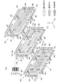
図1は、第1実施例の燃料電池の概略構成を説明するための説明図である。図1は、燃料電池10の断面構成を例示している。燃料電池10は、水素と酸素の供給を受けて発電する固体高分子型燃料電池である。燃料電池10は、例えば、車両等の移動体に搭載されて、移動体の動力源として使用される。また、定置型の電源等としても使用される。燃料電池10は、セル積層体100と、一対のターミナルプレート203a,203bと、一対のインシュレータプレート202a,202bと、スタックマニホールド201と、圧力プレート200と、ケース300と、複数の荷重調整ねじ500を備えている。
A. First embodiment:
FIG. 1 is an explanatory diagram for explaining a schematic configuration of the fuel cell of the first embodiment. FIG. 1 illustrates a cross-sectional configuration of the
セル積層体100は、単セル105を複数積層した構成を備えている。単セル105の形状や構成については、図3を用いて後述する。なお、以後の説明では、このセル積層体100の積層方向に沿った方向をx方向と呼び、x方向に直交し、単セル105の長手方向に沿った方向をy方向と呼び、x方向とy方向に直交する方向をz方向と呼ぶ。セル積層体100の両側には、電極板としてのターミナルプレート203a,203bが配置され、さらに、ターミナルプレート203a,203bの両側にインシュレータプレート202a,202bが配置されている。インシュレータプレート202bの外側には、スタックマニホールド201が配置され、ケース300の外部とセル積層体100との間の反応ガス(燃料ガスや酸化剤ガス等)や冷却媒体の流通経路を構成する。インシュレータプレート202aとケース300との間には、セル積層体100を押圧するための圧力プレート200が配置されている。
The
ケース300は、それぞれ鋼等の金属により形成された、ケース本体305と、板状部材410と、カバー部材420と、シャフト部材430とを備えている。ケース300は、セル積層体100を積層方向(x方向)に圧縮した状態で内側に収容している。
The
図2は、ケース本体の概略構成を説明するための説明図である。図2(A)は、図1に示したケース本体305の上下方向(Z方向)を反転させた状態を例示した斜視図である。図2(B)は、ケース本体305の後方側(図1の右側)を例示した斜視図である。ケース本体305は、略直方体の箱状の外形を備え、前側面部310と、後側面部320と、上面部330と、下面部340と、右側面部350と、左側面部360と、を備えている。ケース本体305の内壁面は、図示しない絶縁性の部材(例えば、樹脂)により被覆されている。
FIG. 2 is an explanatory diagram for explaining a schematic configuration of the case main body. FIG. 2A is a perspective view illustrating a state in which the vertical direction (Z direction) of the case
前側面部310は、上面部330、下面部340、右側面部350、および、左側面部360と概ね直交している。前側面部310は、上面部330、下面部340に対してフランジ状に突出した端辺部310fを備え、中央部分には、前面側開口部311が形成されている。後側面部320は、前側面部310と対向する位置に形成され、上面部330、下面部340、右側面部350、および、左側面部360と概ね直交している。
The front
後側面部320には、ねじ用開口部321と、押圧用開口部322と、シャフト用開口部323とが形成されている。ねじ用開口部321は、ねじ溝を有する荷重調整ねじ500(図1)を挿通するためねじ穴(貫通孔)であり、穴の内側には、荷重調整ねじ500のねじ溝と対応するねじ溝が形成されている。押圧用開口部322は、後述する押圧部材120を挿通するための貫通孔であり、本実施例では、ねじ用開口部321よりも開口面積が大きい円形状の外形を有している。シャフト用開口部323は、シャフト部材430(図1)を挿通するため貫通孔である。ねじ用開口部321、押圧用開口部322およびシャフト用開口部323の数や位置の詳細については図4を用いて後述する。
The rear
上面部330および下面部340は、互いに対向する位置に形成され、それぞれ右側面部350および左側面部360と概ね直交している。下面部340は、中央部分のほぼ全域に下面側開口部341が形成されている。右側面部350および左側面部360は、互いに対向する位置に形成され、外周部が前側面部310、後側面部320、上面部330、および、下面部340の外周部とそれぞれ接続されている。本実施例では、前側面部310と後側面部320は、法線方向がx方向に沿うように形成され、上面部330、下面部340、右側面部、および、左側面部は、x方向と平行に形成される。また、ケース本体305の内側には、セル積層体100のセル電圧を監視するためのモニタ基盤550が右側面部350に沿って配置されている。
The
図1に示すように、前側面部310には、ボルト411によって略矩形形状の板状部材410が取り付けられ、板状部材410によって前面側開口部311が塞がれている。板状部材410には、補機450が取り付けられている。補機450は、例えば、外部からの反応ガスをマニホールドに供給するための配管452,454や、燃料ガス(水素)を送り出すポンプ453等である。また、下面部340には、ボルト421によって略矩形形状のカバー部材420が取り付けられ、カバー部材420によって下面側開口部341が塞がれている。
As shown in FIG. 1, a substantially rectangular plate-
シャフト部材430は、金属などにより形成された棒状の部材であり、x方向に伸びてケース300の内側を貫くように配置されている。シャフト部材430は、ナット431によって、一方の端部が板状部材410に固定され、他方の端部がシャフト用開口部323を挿通させた状態で後側面部320に固定されている。
The
荷重調整ねじ500は、金属などにより形成されたねじ溝を有する棒状の部材であり、基端側が後側面部320のねじ用開口部321にねじ止めされ、先端側が圧力プレート200と接触している。荷重調整ねじ500は、回転によって、後側面部320から圧力プレート200と接触する端部までの長さが調整される。
The
圧力プレート200は、単セル105と同じ形状を有する平板状の外形を備え、ケース本体305の後側面部320とセル積層体100との間に配置されている。圧力プレート200は、ターミナルプレート203a,203bやインシュレータプレート202a,202bよりも十分に厚みが大きく、外部からの押圧力をセル積層体100の表面全体にほぼ均一に伝えることができるものであることが好ましい。圧力プレート200は、セル積層体100から後側面部320に向かう方向に押圧され、荷重調整ねじ500によって移動が規制されている。圧力プレート200、スタックマニホールド201および板状部材410は、セル積層体100を一部に含んで構成される燃料電池スタックの構成部材(例えば、エンドプレート)として用いられていてもよい。
The
セル積層体100は、圧力プレート200と板状部材410によって挟持され、所定の荷重がかけられた状態でケース300の内側に収容されている。すなわち、本実施例のセル積層体100は、x方向に圧縮された状態でケース300の内側に収容されている。
The
図3は、単セルの概略構成を説明するための説明図である。単セル105は、シール一体型膜電極接合体150と、シール一体型膜電極接合体150を両側から挟むように配置される一対のセパレータ160、180(以後「第1のセパレータ160」「第2のセパレータ180」とも呼ぶ)を備えている。シール一体型膜電極接合体150は、膜電極接合体151の周縁部にシールガスケット158が形成された構成を有している。膜電極接合体151は、固体高分子電解質膜152の両側にアノード153とカソード154が配置され、アノード153とカソード154の外側に一対のガス拡散層157を配置した構成を備えている。
FIG. 3 is an explanatory diagram for explaining a schematic configuration of a single cell. The
固体高分子電解質膜152は、フッ素系樹脂材料や炭化水素系樹脂材料で形成され、湿潤状態において良好なプロトン導電性を有している。アノード153とカソード154は、それぞれ、電気化学反応を進行する触媒金属(例えば白金)を担持したカーボン粒子(触媒担持担体)とプロトン伝導性を有する高分子電解質(例えばフッ素系樹脂)を含んで構成されている。ガス拡散層157は、カーボンペーパー等のガス透過性の導電性部材により成形されている。シールガスケット158は、合成樹脂等を膜電極接合体151の周縁部に射出成形することによって形成されている。第1のセパレータ160と第2のセパレータ180は、板状の外形を備え、ガス不透過な導電性部材、例えば、カーボンを圧縮してガス不透過とした緻密質カーボンや、焼成カーボン、あるいはステンレス鋼などの金属材料により形成されている。
The solid
シール一体型膜電極接合体150とセパレータ160、180の各周縁部には、貫通孔が形成され、各単セル105が積層されることによって反応ガス(燃料ガスや酸化ガス)や冷却媒体(例えば、水)を積層方向(x方向)に流通させるためのマニホールドM1〜M6が形成される。具体的には、マニホールドM1には外部から供給された酸化剤ガス(カソード供給ガス)が流通し、マニホールドM2には膜電極接合体151を通過した酸化剤ガスを含むガス(カソード排ガス)が流通する。また、マニホールドM3には外部から供給された燃料ガス(アノード供給ガス)が流通し、マニホールドM4には膜電極接合体151を通過した燃料ガスを含むガス(アノード排ガス)が流通する。また、マニホールドM5には外部から供給された冷却媒体が流通し、マニホールドM6には冷却に供された冷却媒体が流通する。
Through holes are formed in the peripheral portions of the seal-integrated
第1のセパレータ160が備える2つの主面のうち、膜電極接合体151に対向する一方の主面には、マニホールドM3を流通する燃料ガス(アノード供給ガス)が流れ込む図示しない流路溝が形成されている。また、第1のセパレータ160の他方の主面には、マニホールドM5を流通する冷却媒体が流れ込む流路溝161が形成されている。第2のセパレータ180が備える2つの主面のうち、膜電極接合体151に対向する一方の主面には、マニホールドM1を流通する酸化剤ガス(カソード供給ガス)が流れ込む流路溝181が形成されている。また、第2のセパレータ180の他方の主面には、マニホールドM5を流通する冷却媒体が流れ込む図示しない流路溝が形成されている。
Of the two main surfaces of the
シール一体型膜電極接合体150およびセパレータ160、180は、それぞれ四隅に切欠き155、165、185が形成された略矩形の平板形状を有している。また、シール一体型膜電極接合体150およびセパレータ160、180の長手方向(y方向)の端辺部のうち、ケース300に収容されたときに下面部340と対向する側の端辺部の中央付近には、切欠き156、166、186が形成されている。
The seal-integrated
図4は、ケース本体のねじ用開口部と押圧用開口部とシャフト用開口部の位置を説明するための説明図である。図4は、燃料電池10の後側面部320側をx方向から見た状態を例示している。また、図4は、セル積層体100の位置とモニタ基盤550の位置を破線で示している。セル積層体100と圧力プレート200とは、x方向から見たときの形状がほぼ等しいため、図4の破線は、圧力プレート200の位置も示している。
FIG. 4 is an explanatory diagram for explaining the positions of the screw opening, the pressing opening, and the shaft opening of the case body. FIG. 4 illustrates a state where the
ケース本体305の後側面部320には、8つのねじ用開口部321と、2つの押圧用開口部322と、3つのシャフト用開口部323とが形成されている。8つのねじ用開口部321は、x方向から見たときに、セル積層体100の外周部と対向する位置にそれぞれ形成されている。こうすることで、各ねじ用開口部321に荷重調整ねじ500を挿通したときに、各荷重調整ねじ500がセル積層体100の外周部を押圧するため、積層方向(x方向)に圧縮されたセル積層体100の反力によってセル積層体100の外周部が撓むことを抑制することができる。また、ねじ用開口部321は、押圧用開口部322を囲むように配置されている。こうすることで、押圧用開口部322を介して押圧部材120により圧力プレート200を押圧したときに、押圧部材120に押圧されている点を中心にして圧力プレート200の表面が撓んだ場合であっても、各ねじ用開口部321から圧力プレート200の表面までの距離を概ね等しくすることができる。これにより、押圧用開口部322に荷重調整ねじ500を取り付けた後に、各荷重調整ねじ500が圧縮されたセル積層体100からの反力を概ね等しく負担することができる。
The
2つの押圧用開口部322は、x方向から見たときに、セル積層体100の重心位置GCの両側にそれぞれ配置されている。言い換えれば、2つの押圧用開口部322は、x方向から見たときに、セル積層体100の重心位置GCが2つの押圧用開口部322の間となるように配置されている。これにより、各押圧用開口部322を介して押圧部材120により圧力プレート200を押圧したときに、圧力プレート200を押圧する力の合力をセル積層体100の重心位置GC付近に作用させることができる。よって、合力の作用点と重心位置GCのずれにともなうモーメントの発生を抑制でき、セル積層体100を積層方向(x方向)に真っ直ぐ圧縮することができる。
The two
本実施例では、2つの押圧用開口部322は、セル積層体100の重心位置GCからの距離Dが互いに等しくなる位置に形成されている。そのため、圧力プレート200を押圧する力の合力をよりセル積層体100の重心位置GC付近に作用させることができる。また、本実施例では、押圧用開口部322は、円柱状の押圧部材120を挿通可能な円形の開口形状を有している。そのため、距離Dは、セル積層体100の重心位置GCから、セル積層体100の重心位置GCに最も近い押圧用開口部322の縁端部までの距離として示しているが、距離Dは、セル積層体100の重心位置GCから、押圧用開口部322の中心点までの距離としてもよい。
In the present embodiment, the two
なお、2つの押圧用開口部322は、x方向から見たときに、セル積層体100の重心位置GCの両側にそれぞれ配置されていれば、セル積層体100の重心位置GCからの距離が異なるように配置されていてもよい。複数の押圧部材120により圧力プレート200を押圧したときの合力の作用位置をセル積層体100の重心位置GCに正確に一致させなくても、セル積層体100を積層方向に真っ直ぐ圧縮することができるためである。また、押圧用開口部322は、内側にねじ溝を備えていてもよい。
If the two
3つのシャフト用開口部323は、後側面部320の下面部340と接続する端辺に沿って並んで配置されている。3つのシャフト用開口部323のうち、外側の2つシャフト用開口部323は、x方向から見たときに、シール一体型膜電極接合体やセパレータの切欠き155、165、185によって形成される溝部と対向する位置に形成されている。3つのシャフト用開口部323のうち、真ん中のシャフト用開口部323は、シール一体型膜電極接合体やセパレータの切欠き156、166、186よって形成される溝部と対向する位置に形成されている。このように、3つのシャフト用開口部323は、セル積層体100と対向せず、上述した溝部を介してケース本体305の反対側に取り付けられている板状部材410と対向している。3つのシャフト用開口部323は、後側面部320の下面部340側に並んで配置されているため、シャフト用開口部323と板状部材410との間に渡されたシャフト部材430により、積層方向に圧縮されたセル積層体100の反力を負担することができる。これにより、下面側開口部341が形成されている下面部340の変形を抑制することができる。
The three
図5は、燃料電池10の製造方法の手順を説明するためのフローチャートである。燃料電池10を製造するにあたり、まず、モニタ基盤550(図2(A))を取り付けたケース本体305を製造装置600にセットする(ステップS110)。
FIG. 5 is a flowchart for explaining the procedure of the manufacturing method of the
図6は、ケース本体を製造装置にセットする状態を例示した説明図である。製造装置600は、燃料電池を製造する際に使用される装置であって、平板状の台部610と、固定ガイド620と、移動ガイド630と、を備えている。固定ガイド620は、長尺状の外形を備え、台部610上に固定されている。移動ガイド630は、固定ガイド620と同様に長尺状の外形を備え、固定ガイド620と上面をそろえた状態で水平方向に移動可能に構成されている。この製造装置600の台部610の上にケース本体305を設置する。このとき、ケース本体305は、下面側開口部341を介して固定ガイド620と移動ガイド630がケース本体305の内側にくるように配置される。ケース本体305を製造装置600にセットした後、単セル105をケース本体305の内側に収容する(図5のステップS120)。
FIG. 6 is an explanatory view illustrating a state in which the case main body is set in the manufacturing apparatus. The
図7は、単セルをケース本体の内側に収容する状態を例示した説明図である。まず、ケース本体305の前面側開口部311を介してケース本体305の内側に位置する移動ガイド630の一部をケース本体305の外側に引き出す。一部がケース本体305の外側に引き出された移動ガイド630および固定ガイド620の上面に、圧力プレート200、インシュレータプレート202a,ターミナルプレート203a、複数の単セル105(セル積層体100)、ターミナルプレート203b,インシュレータプレート202b、スタックマニホールド201を順に配置する。その後、加圧機構460によって、補機450が取り付けられた板状部材410を押圧することにより、セル積層体100を積層方向(x方向)に圧縮する。セル積層体100は、積層方向(X方向)圧縮された状態でケース本体305の内側に収容される。このとき、板状部材410の押圧により板状部材410が前側面部310に当接する。
FIG. 7 is an explanatory view illustrating a state in which the single cell is accommodated inside the case body. First, a part of the
図8は、板状部材を前側面部に固定する状態を例示した説明図である。板状部材410を前側面部310に当接させた状態で、ボルト411によって板状部材410を前側面部310に固定する(図5のステップS130)。これにより、セル積層体100は、積層方向に所定の荷重が加えられた状態でケース本体305の内側に保持される。以後、ステップS130を経て、前側面部310に板状部材410が取り付けられた状態の燃料電池を仮組立体11とも呼ぶ。ステップS130の後、仮組立体11を製造装置600から取り外す。次に、仮組立体11にシャフト部材430の取り付けをおこなう(ステップS140)。
FIG. 8 is an explanatory view illustrating a state in which the plate-like member is fixed to the front side surface portion. With the plate-
図9は、仮組立体にシャフト部材を取り付ける状態を例示した説明図である。図9(A)に示すように、まず、仮組立体11を取付装置650にセットする。取付装置650は、仮組立体11を設置するための設置台であって、上面に図示しない複数のローラが配置されている。取付装置650の上面にセル積層体100が接触するようにして仮組立体11を取付装置650に配置する。その後、仮組立体11のシャフト用開口部323からシャフト部材430を挿入する。シャフト部材430を後側面部320から板状部材410まで渡した後、図9(B)に示すように、ナット431によって、シャフト部材430の両端をそれぞれ、後側面部320と板状部材410に固定する。仮組立体11にシャフト部材430を取り付けた後、セル積層体100の積層方向(x方向)の圧縮荷重を調整する(ステップS150)。
FIG. 9 is an explanatory view illustrating a state in which the shaft member is attached to the temporary assembly. As shown in FIG. 9A, first, the
図10は、セル積層体の圧縮荷重を調整する方法を説明するための説明図である。図10(A)に示すように、まず、押圧用開口部322に棒状の押圧部材120を挿入し、押圧部材120によって圧力プレート200を押圧する。圧力プレート200の押圧によりセル積層体100が積層方向(x方向)に圧縮される。すなわち、押圧部材120による圧力プレート200の押圧力を調整することによって、セル積層体100の積層方向の圧縮荷重を調整することができる。本実施例では、押圧部材120は、加圧設備700の一部として構成され、加圧設備700が有する駆動部710から動力を得て任意の荷重量によって圧力プレート200を押圧することができる。加圧設備700は、荷重測定部720を備え、押圧部材120が圧力プレート200を押圧する荷重量を検出することができる。すなわち、加圧設備700は、セル積層体100の積層方向(x方向)の圧縮荷重を検出することができる。そのため、セル積層体100の圧縮荷重を検出ための検出部を燃料電池自体が備える必要がなく、燃料電池の軽量化や、製造コストの抑制等を図ることができる。
FIG. 10 is an explanatory diagram for explaining a method of adjusting the compressive load of the cell stack. As shown in FIG. 10A, first, a rod-shaped
セル積層体100の積層方向(x方向)の圧縮荷重が所定値となったときに、この圧縮荷重を維持した状態で、図10(B)に示すように、荷重調整ねじ500の取り付けをおこなう。圧縮荷重は、例えば、36.5kN程度とすることができる。荷重調整ねじ500の取り付けは、後側面部320に形成されている8つのねじ用開口部321にそれぞれ荷重調整ねじ500をねじ込むことによっておこなう。このときのねじ込みトルクは、例えば、1〜2.5Nmとすることができる。荷重調整ねじ500の締め付けは、5Nm±30%の範囲、すなわち、3.5〜6.5Nmの範囲とすることが好ましい。
When the compressive load in the stacking direction (x direction) of the
これは、荷重調整ねじ500を圧力プレート200に対して確実に着座させるためには、締め付けトルクの下限値が3Nm以上であることが好ましいためである。一方、締め付けトルクの上限値は、締め付けトルクによって生じる荷重調整ねじ500の軸力によって、圧力プレート200がほとんど移動しない値とすることが好ましい。加圧設備700によってセル積層体100の積層方向の圧縮荷重を36.5kNに維持した状態で荷重調整ねじ500を取り付ける場合には、8本の荷重調整ねじ500の1本あたりの軸力を4.56(≒36.5/8)kNより小さい値とすることが好ましい。本実施例では、締め付けトルクが6.5Nm以下の場合には軸力が1.6kN以下となる荷重調整ねじ500を使用しているため、締め付けトルクによる圧力プレート200の移動を抑制することができる。
This is because the lower limit value of the tightening torque is preferably 3 Nm or more in order for the
8本の荷重調整ねじ500を仮組立体11に取り付けた後、図10(C)に示すように、仮組立体11から押圧部材120を抜き取る。押圧部材120を抜き取った後であっても、荷重調整ねじ500によって圧力プレート200の位置はほとんど移動しないため、セル積層体100は、圧力プレート200と板状部材410によって、積層方向の圧縮荷重が所定値(例えば、36.5kN)となる状態で保持される。なお、荷重調整ねじ500を取り付けた後、押圧部材120を抜き取る前に、荷重調整ねじ500に対して4Nm±30%のトルクをかけて荷重調整ねじ500の確実な着座を確認する検査をおこなってもよい。押圧部材120の抜き取りの後、仮組立体11にカバー部材420を取り付ける(ステップS160)。
After the eight load adjustment screws 500 are attached to the
図11は、仮組立体にカバー部材を取り付ける状態を例示した説明図である。図11(A)に示すように、下面側開口部341を塞ぐように、ボルト421によってカバー部材420を下面部340に取り付ける。これにより、図11(A)に示すように、燃料電池10が完成する。
FIG. 11 is an explanatory view illustrating a state in which the cover member is attached to the temporary assembly. As shown in FIG. 11A, the
本実施例の押圧用開口部322は、請求の範囲の「第1の開口部」に該当する。本実施例のねじ用開口部321と荷重調整ねじ500は、請求の範囲の「固定部」に該当する。
本実施例のねじ用開口部321は、請求の範囲の「めねじ部」や「第2の開口部」に該当する。
The
The
以上説明した、本実施例の燃料電池10によれば、押圧用開口部322によって、ケース本体305の外部から圧力プレート200を積層方向(x方向)に押圧することができ、また、圧力プレート200を積層方向に押圧した状態において、荷重調整ねじ500をねじ用開口部321に取り付けることによって、圧力プレート200の位置を固定することができる。従って、ケース本体305の内側に積層方向に圧縮されたセル積層体100を収容する燃料電池10を容易に製造することができる。
According to the
従来、ケース本体の内側に積層方向に圧縮されたセル積層体を収容する燃料電池を製造する方法として、例えば、ケースの外部からねじ部材によって圧力プレートを押圧することでセル積層体の圧縮荷重を調整する方法が知られている。しかし、この場合、積層方向(x方向)に圧縮されるセル積層体の反力に抗してねじ込みをおこなうため、ねじ穴から切り粉が発生する問題があった。また、3箇所以上でセル積層体を押圧する場合には、1以上の箇所においてセル積層体を十分に押圧することができず、押圧力の合力をセル積層体100の重心位置GC付近に作用させることが容易ではなかった。また、セル積層体の圧縮荷重を燃料電池10の外部から検出することが容易ではないため、燃料電池10の内部に圧縮荷重を検出するための検出部を設置する必要があり、製造コストが高く、重量が増加する問題があった。また、製造工程において、使用するねじの選定をおこなうため、予め、セル積層体を圧縮してセル積層体の寸法を測定した後に、セル積層体の圧縮を開放する開放工程が必要であった。
Conventionally, as a method of manufacturing a fuel cell that accommodates a cell stack compressed in the stacking direction inside a case body, for example, the compression load of the cell stack is pressed by pressing a pressure plate with a screw member from the outside of the case. A method of adjusting is known. However, in this case, since the screwing is performed against the reaction force of the cell stack that is compressed in the stacking direction (x direction), there is a problem that chips are generated from the screw holes. Further, when the cell stack is pressed at three or more locations, the cell stack cannot be sufficiently pressed at one or more locations, and the resultant force of the pressing force acts near the center of gravity GC of the
一方、本実施例の燃料電池10によれば、押圧部材120によってセル積層体100を圧縮した状態で荷重調整ねじ500を取り付けるため、ねじ用開口部321からの切り粉の発生を抑制することができる。また、押圧部材120によって2箇所でセル積層体100を押圧するため、押圧力の合力をセル積層体100の重心位置GC付近に作用させることができる。また、押圧用開口部322を介してケース本体305の外部から圧力プレート200を押圧するため、加圧設備700などの外部装置によって、セル積層体100の圧縮荷重を検出することができる。また、押圧部材120によってセル積層体100を圧縮した状態で荷重調整ねじ500を取り付けるため、従来の開放工程を要さず、製造工程の短縮化を図ることができる。
On the other hand, according to the
また、他の従来例として、例えば、ケースとセル積層体との間に平板状のシム板を複数枚挟み込むことによってセル積層体の圧縮荷重を調整する方法が知られている。しかし、この場合、シム板によって燃料電池の自重が増加する問題や、シム板の厚みによる圧縮荷重の微調整が容易ではないなどの問題があった。一方、本実施例の燃料電池10によれば、荷重調整ねじ500によって、圧力プレート200の移動を規制するため、燃料電池10の重量の増加を抑制することができる。また、外部の加圧設備700によってセル積層体100を圧縮するため、圧縮荷重の微調整を容易におこなうことができる。
As another conventional example, for example, a method of adjusting the compressive load of the cell stack by sandwiching a plurality of flat shim plates between the case and the cell stack is known. However, in this case, there is a problem that the self weight of the fuel cell is increased by the shim plate, and a fine adjustment of the compression load due to the thickness of the shim plate is not easy. On the other hand, according to the
B.第2実施例:
図12は、第2実施例のケース本体における押圧用開口部の位置を説明するための説明図である。図12は、第1実施例の図4と対応している。第1実施例の燃料電池10は、2つの押圧用開口部322が形成されたケース本体305を備えていたが、第2実施例の燃料電池10bは、3つの押圧用開口部322が形成されたケース本体305bを備えている。第2実施例の燃料電池10bのその他の構成については、第1実施例の燃料電池10と同様のため、説明を省略する。
B. Second embodiment:
FIG. 12 is an explanatory diagram for explaining the position of the pressing opening in the case body of the second embodiment. FIG. 12 corresponds to FIG. 4 of the first embodiment. The
ケース本体305bの後側面部320bに形成された3つの押圧用開口部322は、x方向から見たときに、セル積層体100の重心位置GCを囲むようにそれぞれ配置されている。言い換えれば、3つの押圧用開口部322は、x方向から見たときに、セル積層体100の重心位置GCが3つの押圧用開口部322により囲まれる領域Aの内側となるように配置されている。これにより、各押圧用開口部322を介して押圧部材120により圧力プレート200を押圧したときに、圧力プレート200を押圧する力の合力をセル積層体100の重心位置GC付近に作用させることができる。
The three
本実施例では、押圧用開口部322は、円柱状の押圧部材120を挿通可能な円形の開口形状を有している。そのため、領域Aは、各開口部の中心点を結んだ領域として構成されている。また、x方向から見たときに、領域Aの重心と、セル積層体100の重心位置GCが一致する。この構成であれば、圧力プレート200を押圧する力の合力をよりセル積層体100の重心位置GC付近に作用させることができる。なお、領域Aは、3つの押圧用開口部322の各縁端部を繋いで形成される領域のうち、最小の領域として構成されてもよい。
In the present embodiment, the
以上説明した、本実施例の燃料電池10bによれば、ケース本体305bに3つの押圧用開口部322が形成されている場合であっても、3つの押圧部材120によってセル積層体100を積層方向(x方向)に真っ直ぐ圧縮することができるため、燃料電池10bを容易に製造することができる。なお、4つの押圧部材120によってセル積層体100を圧縮すると、そのうちの3つの押圧部材120が圧力プレート200を押圧し、残りの1つの押圧部材120は圧力プレート200を十分に押圧することができない状態が発生しうるため、x方向から見たときに、圧力プレート200を押圧する力の合力が作用する位置がセル積層体100の重心位置GCからずれるおそれがある。このことから、複数の押圧部材120によって圧力プレート200を押圧する場合には、押圧部材120の数を3つ以下にすることが好ましい。
According to the
C.第3実施例:
図13は、第3実施例のケース本体における押圧用開口部の位置を説明するための説明図である。図13は、第1実施例の図4と対応している。第3実施例の燃料電池10cは、押圧用開口部322が1つのみ形成されたケース本体305cを備えている。第3実施例の燃料電池10cのその他の構成については、第1実施例の燃料電池10と同様のため、説明を省略する。
C. Third embodiment:
FIG. 13 is an explanatory diagram for explaining the position of the pressing opening in the case body of the third embodiment. FIG. 13 corresponds to FIG. 4 of the first embodiment. The
ケース本体305cの後側面部320cに形成された1つの押圧用開口部322は、x方向から見たときに、セル積層体100の重心位置GCと対向している。言い換えれば、押圧用開口部322は、x方向から見たときに、セル積層体100の重心位置GCが開口部の内側に位置するように配置されている。これにより、押圧用開口部322を介して押圧部材120により圧力プレート200を押圧したときに、圧力プレート200を押圧する力をセル積層体100の重心位置GC付近に作用させることができる。
One
以上説明した、本実施例の燃料電池10cによれば、ケース本体305cに押圧用開口部322が1つのみ形成されている場合であっても、押圧部材120によってセル積層体100を積層方向(x方向)に真っ直ぐ圧縮することができるため、燃料電池10cを容易に製造することができる。
According to the
D.変形例:
なお、この発明は上記の実施例や実施形態に限られるものではなく、その要旨を逸脱しない範囲において種々の態様において実施することが可能であり、例えば次のような変形も可能である。
D. Variation:
The present invention is not limited to the above-described examples and embodiments, and can be implemented in various modes without departing from the gist thereof. For example, the following modifications are possible.
D−1.変形例1:
図14は変形例1のケース本体における押圧用開口部の位置を説明するための説明図である。第1〜3実施例では、押圧用開口部322は、円形の開口形状を有しているものとして説明したが、押圧部材120を挿通可能な大きさを有していれば、円形以外の任意の開口形状であってもよい。例えば、図14に示すように、燃料電池10dは、複数の押圧部材120を挿通可能な開口形状322dを有していてもよい。一方、押圧部材120を挿通可能な大きさを有していれば、ねじ用開口部321より開口面積が小さくてもよい。
D-1. Modification 1:
FIG. 14 is an explanatory diagram for explaining the position of the pressing opening in the case body of the first modification. In the first to third embodiments, the
D−2.変形例2:
図15は変形例2のケース本体における押圧用開口部の位置を説明するための説明図である。第1〜3実施例では、押圧用開口部322は、ケース本体305の後側面部320に形成されているものとして説明したが、ケース本体305の外部から押圧部材120によって圧力プレート200を圧縮方向(x方向)に押圧可能な構成であれば、押圧用開口部322は、ケース本体305の後側面部320以外の部分に形成されていてもよい。
D-2. Modification 2:
FIG. 15 is an explanatory diagram for explaining the position of the pressing opening in the case body of the second modification. In the first to third embodiments, the
図15を用いてその一例を示す。まず、図15(A)に示すように、平板部121fと棒状部121bを有する押圧部材121を用意する。棒状部121bは、一方の端部が押圧部材121fの端面に接続され、他方の端部が図示しない回動駆動部に接続されている。図15(B)に示すように、変形例2に係る燃料電池の仮組立体11eは、ケース本体305eの上面部330に長尺状の開口部である押圧用開口部322eを備えている。この押圧用開口部322eを介して平板部121fがケース本体305eの内側となるように押圧部材121を挿入する。その後、図15(C)に示すように、棒状部121bを回転軸にして押圧部材121を回転させる。これにより、平板部121fが圧力プレート200eを押圧し、セル積層体100を積層方向に圧縮することができる。
An example is shown using FIG. First, as shown in FIG. 15A, a pressing
D−3.変形例3:
図16は変形例3の燃料電池における固定部を説明するための説明図である。本実施例では、セル積層体100から後側面部320に向かう方向(x方向)に押圧された圧力プレート200の移動を規制するための固定部として、ねじ用開口部321と荷重調整ねじ500が用いられているが、圧力プレート200の移動を規制可能な構成であれば、固定部として、ねじ用開口部321と荷重調整ねじ500以外の構成を採用してもよい。例えば、図16(A)に示すように、圧力プレート200と、後側面部320との間に固定部としての棒状部材501を挟み込むようにしてもよい。
D-3. Modification 3:
FIG. 16 is an explanatory diagram for explaining a fixing portion in the fuel cell of the third modification. In the present embodiment, a
また、図16(B)に示すように、貫通孔のねじ用開口部321の代わりに貫通していないめねじ穴321gを後側面部320の圧力プレート200と対向する位置に形成し、荷重調整ねじ500を取り付けてもよい。また、ねじ用開口部321の代わりに、上面部330や下面部340、もしくは、右側面部350や左側面部360に開口部形成し、例えば、上述した図15の押圧部材121を回転させた後に固定することによって圧力プレート200の位置を固定してもよい。また、セル積層体100を圧縮した状態で、圧力プレート200をケース本体305に接着することにより、圧力プレート200の位置を固定してもよい。この場合は、接着剤が固定部として機能する。
Further, as shown in FIG. 16B, instead of the screw opening 321 of the through hole, a
D−4.変形例4:
本実施例では、ねじ用開口部321と押圧用開口部322は、燃料電池10の後側面部320に形成されているものとして説明したが、ねじ用開口部321と押圧用開口部322は、燃料電池10の前側にある板状部材410に形成されていてもよい。この場合であっても、押圧用開口部322を介してケース本体305の外部からセル積層体100を積層方向に圧縮でき、また、押圧部材120によってセル積層体100を圧縮した状態で、ねじ用開口部321に荷重調整ねじ500を取り付けることができる。
D-4. Modification 4:
In the present embodiment, the
D−5.変形例5:
本実施例では、燃料電池10は、セル積層体100とは別に圧力プレート200を備えているものとして説明したが、圧力プレート200は、セル積層体100の積層方向端部において、押圧部材120からの応力を受けることが可能な部材であればよく、セパレータなど、セル積層体100の一部を構成する部材を圧力プレートとして兼用してもよい。
D-5. Modification 5:
In the present embodiment, the
D−6.変形例6:
本実施例では、押圧用開口部322は、ケース本体305に1つないし3つ形成されているものとして説明したが、4つ以上形成されていても、任意の1ないし3つの押圧用開口部322に押圧部材120を挿通させてセル積層体100を圧縮することができるため、燃料電池10は、4つ以上の押圧用開口部322を備えていてもよい。
D-6. Modification 6:
In the present embodiment, one or three
D−7.変形例7:
本実施例では、ケース本体305を構成する各部位を、前側面部310、後側面部320、上面部330、下面部340、右側面部350、および、左側面部360と呼んで説明したが、これらの名前は説明のためのものであり、燃料電池10の設置方向等とは関係ない。また、ケース本体305は、前側面部310、後側面部320、上面部330、下面部340、右側面部350、および、左側面部360の境界が明確に特定できない形状であってもよく、境界は任意に設定することができる。
D-7. Modification 7:
In the present embodiment, the parts constituting the case
D−8.変形例8:
本実施例では、ケース本体305の後側面部320には、ねじ用開口部321、押圧用開口部322、および、シャフト用開口部323の3種類の開口部が形成されているものとして説明したが、後側面部320には、3種類以上の開口部が形成されていてもよい。また、ケース本体305は、シャフト用開口部323を備えていなくてもよい。
D-8. Modification 8:
In the present embodiment, it has been described that the rear
D−9.変形例9:
本実施例では、燃料電池に固体高分子型燃料電池を用いたが、リン酸型燃料電池、溶融炭酸塩型燃料電池、固体酸化物形燃料電池等、種々の燃料電池を用いることができる。
D-9. Modification 9:
In this embodiment, the polymer electrolyte fuel cell is used as the fuel cell, but various fuel cells such as a phosphoric acid fuel cell, a molten carbonate fuel cell, and a solid oxide fuel cell can be used.
10…燃料電池
11…仮組立体
100…セル積層体
105…単セル
120…押圧部材
150…シール一体型膜電極接合体
151…膜電極接合体
152…固体高分子電解質膜
153…アノード
154…カソード
157…ガス拡散層
158…シールガスケット
160…第1のセパレータ
180…第2のセパレータ
200…圧力プレート
201…スタックマニホールド
202…インシュレータプレート
203…ターミナルプレート
300…ケース
305…ケース本体
310…前側面部
311…前面側開口部
320…後側面部
321…ねじ用開口部
322…押圧用開口部
323…シャフト用開口部
330…上面部
340…下面部
341…下面側開口部
350…右側面部
360…左側面部
410…板状部材
411…ボルト
420…カバー部材
421…ボルト
430…シャフト部材
431…ナット
450…補機
452…配管
453…ポンプ
460…加圧機構
500…荷重調整ねじ
550…モニタ基盤
600…製造装置
610…台部
620…固定ガイド
630…移動ガイド
650…取付装置
700…加圧設備
710…駆動部
720…荷重測定部
DESCRIPTION OF
Claims (11)
複数の燃料電池セルを積層したセル積層体と、
前記セル積層体を内部に収容するケースと、
前記ケースの内部において、前記セル積層体の積層方向における端部と、前記ケースとの間に配置される圧力プレートと、を備え、
前記ケースは、前記ケースの外部から前記圧力プレートを前記積層方向に押圧するための押圧部材を前記圧力プレートに接触させるために用いることのできる第1の開口部と、前記セル積層体を前記積層方向に圧縮した状態で前記圧力プレートの位置を固定することのできる固定部と、を備え、
前記第1の開口部は、前記押圧部材を前記第1の開口部に挿入して前記圧力プレートを押圧した後に、前記第1の開口部から前記押圧部材を引き抜くために用いられる開口部であり、
前記固定部は、前記積層方向において前記圧力プレートと対向しているめねじ部と、前記めねじ部に基端側が接続され、先端側が前記圧力プレートと接触するねじ部材と、を備える、燃料電池。 A fuel cell,
A cell stack in which a plurality of fuel cells are stacked;
A case for accommodating the cell stack inside,
Inside the case, comprising an end portion in the stacking direction of the cell stack, and a pressure plate disposed between the case,
The case includes a first opening that can be used to contact a pressing member for pressing the pressure plate in the stacking direction from the outside of the case, and the cell stack. A fixing part capable of fixing the position of the pressure plate in a compressed state in a direction,
The first opening is an opening used to pull out the pressing member from the first opening after inserting the pressing member into the first opening and pressing the pressure plate. ,
The fixing portion includes a female screw portion facing the pressure plate in the stacking direction, and a screw member having a proximal end connected to the female screw portion and a distal end side contacting the pressure plate. .
前記第1の開口部は、前記積層方向において前記圧力プレートと対向している、燃料電池。 The fuel cell according to claim 1, wherein
The fuel cell, wherein the first opening is opposed to the pressure plate in the stacking direction.
複数の燃料電池セルを積層したセル積層体と、
前記セル積層体を内部に収容するケースと、
前記ケースの内部において、前記セル積層体の積層方向における端部と、前記ケースとの間に配置される圧力プレートと、を備え、
前記ケースは、互いに開口面積が異なり、前記積層方向において、それぞれ前記圧力プレートと対向する第1の開口部及び第2の開口部を備えており、
前記第1の開口部は、前記ケースの外部から前記圧力プレートを前記積層方向に押圧するための押圧部材を前記第1の開口部に挿入して前記圧力プレートを押圧した後に、前記第1の開口部から前記押圧部材を引き抜くために用いられる開口部である、燃料電池。 A fuel cell,
A cell stack in which a plurality of fuel cells are stacked;
A case for accommodating the cell stack inside,
Inside the case, comprising an end portion in the stacking direction of the cell stack, and a pressure plate disposed between the case,
The case has a first opening and a second opening that are opposed to the pressure plate in the stacking direction, respectively, and have different opening areas.
The first opening is formed by inserting a pressing member for pressing the pressure plate in the stacking direction from the outside of the case into the first opening and pressing the pressure plate. A fuel cell, which is an opening used for pulling out the pressing member from the opening.
前記第1の開口部は、前記ケースに1つないし3つ形成されている、燃料電池。 The fuel cell according to claim 3, wherein
One to three of the first openings are formed in the case.
前記第1の開口部は、前記ケースに2つまたは3つ形成され、
各前記第1の開口部は、前記積層方向から見たときに、前記燃料電池セルの重心位置が、2つの前記第1の開口部の間、または、3つの前記第1の開口部により囲まれる領域の内側となるようにそれぞれ配置されている、燃料電池。 The fuel cell according to claim 3 or 4,
Two or three first openings are formed in the case,
When viewed from the stacking direction, each of the first openings has a center of gravity position of the fuel cell surrounded by the two first openings or by the three first openings. Each of the fuel cells is arranged so as to be inside the area to be stored.
前記第1の開口部は、前記ケースに1つ形成され、前記積層方向から見たときに、前記燃料電池セルの重心位置と対向する、燃料電池。 The fuel cell according to claim 3 or 4,
One said 1st opening part is formed in the said case, and when it sees from the said lamination direction, the fuel cell facing the gravity center position of the said fuel cell.
前記第2の開口部は、内周部にねじ溝を備えるめねじ部を有する、燃料電池。 The fuel cell according to any one of claims 3 to 6,
The second opening portion has a female screw portion having a thread groove on an inner peripheral portion thereof.
複数の燃料電池セルを積層したセル積層体と、前記セル積層体を収容するためのケースと、を準備する準備工程と、
前記セル積層体の積層方向の端部が圧力プレートを介して前記ケースと対向する状態で、前記セル積層体を前記ケースの内部に収容する収容工程と、
前記ケースの外部から前記ケースの側面部に設けられた第1の開口部に押圧部材を挿入して圧力プレートを押圧することにより、前記ケースの内部に収容されている前記セル積層体を積層方向に圧縮する圧縮工程と、
前記押圧部材によって前記セル積層体が圧縮されている状態において、前記圧力プレートの位置を固定する固定工程と、
前記第1の開口部から前記押圧部材を引き抜く工程と、
を備える製造方法。 A fuel cell manufacturing method comprising:
A preparation step of preparing a cell stack in which a plurality of fuel cells are stacked, and a case for housing the cell stack,
An accommodating step of accommodating the cell stack in the case in a state where an end portion in the stacking direction of the cell stack is opposed to the case via a pressure plate;
The cell stack accommodated in the case is stacked in the stacking direction by inserting a pressing member into the first opening provided in the side surface of the case from the outside of the case and pressing the pressure plate. A compression step of compressing
In the state where the cell stack is compressed by the pressing member, a fixing step of fixing the position of the pressure plate;
Extracting the pressing member from the first opening;
A manufacturing method comprising:
前記収容工程は、前記セル積層体の積層方向の端部が圧力プレートを介して前記側面部と対向するように前記セル積層体を前記ケースの内部に収容する工程を含み、
前記固定工程は、前記圧力プレートと前記側面部の第2の開口部との間にねじ部材を取り付ける工程を含む、製造方法。 In the manufacturing method of Claim 8,
The accommodating step includes a step of accommodating the cell stack in the case so that an end portion in the stacking direction of the cell stack faces the side surface portion via a pressure plate,
The fixing step includes a step of attaching a screw member between the pressure plate and the second opening of the side surface portion.
前記固定工程は、前記押圧部材による前記押圧によって前記セル積層体の圧縮荷重が所定値となったときに、前記ねじ部材の取り付けをおこない、前記ねじ部材を取り付けた後に、前記押圧部材による前記押圧を解除する工程を含む、製造方法。 In the manufacturing method of Claim 9,
In the fixing step, when the compressive load of the cell stack reaches a predetermined value due to the pressing by the pressing member, the screw member is attached, and after the screw member is attached, the pressing by the pressing member is performed. The manufacturing method including the process of canceling | releasing.
前記固定工程は、前記押圧部材による押圧力を検出可能な前記ケースの外部の装置を用いて前記セル積層体の圧縮荷重を検出する工程を含む、製造方法。 In the manufacturing method of Claim 10,
The said fixing process is a manufacturing method including the process of detecting the compressive load of the said cell laminated body using the apparatus outside the said case which can detect the pressing force by the said pressing member.
Priority Applications (7)
| Application Number | Priority Date | Filing Date | Title |
|---|---|---|---|
| JP2011142945A JP5664477B2 (en) | 2011-06-28 | 2011-06-28 | Fuel cell and fuel cell manufacturing method |
| CA2838923A CA2838923C (en) | 2011-06-28 | 2012-06-25 | Fuel cell, and method for production of fuel cell |
| DE112012002733.7T DE112012002733T8 (en) | 2011-06-28 | 2012-06-25 | Fuel cell and method of manufacturing a fuel cell |
| US14/128,775 US9559378B2 (en) | 2011-06-28 | 2012-06-25 | Fuel cell stack case with pressure plate |
| CN201280031406.5A CN103620848B (en) | 2011-06-28 | 2012-06-25 | Fuel cell and the method for the production of fuel cell |
| KR1020137034518A KR101810086B1 (en) | 2011-06-28 | 2012-06-25 | Fuel cell, and method for production of fuel cell |
| PCT/IB2012/001249 WO2013001338A1 (en) | 2011-06-28 | 2012-06-25 | Fuel cell, and method for production of fuel cell |
Applications Claiming Priority (1)
| Application Number | Priority Date | Filing Date | Title |
|---|---|---|---|
| JP2011142945A JP5664477B2 (en) | 2011-06-28 | 2011-06-28 | Fuel cell and fuel cell manufacturing method |
Publications (3)
| Publication Number | Publication Date |
|---|---|
| JP2013012325A JP2013012325A (en) | 2013-01-17 |
| JP2013012325A5 JP2013012325A5 (en) | 2013-11-14 |
| JP5664477B2 true JP5664477B2 (en) | 2015-02-04 |
Family
ID=46514712
Family Applications (1)
| Application Number | Title | Priority Date | Filing Date |
|---|---|---|---|
| JP2011142945A Active JP5664477B2 (en) | 2011-06-28 | 2011-06-28 | Fuel cell and fuel cell manufacturing method |
Country Status (7)
| Country | Link |
|---|---|
| US (1) | US9559378B2 (en) |
| JP (1) | JP5664477B2 (en) |
| KR (1) | KR101810086B1 (en) |
| CN (1) | CN103620848B (en) |
| CA (1) | CA2838923C (en) |
| DE (1) | DE112012002733T8 (en) |
| WO (1) | WO2013001338A1 (en) |
Families Citing this family (23)
| Publication number | Priority date | Publication date | Assignee | Title |
|---|---|---|---|---|
| JP5828326B2 (en) | 2013-02-07 | 2015-12-02 | トヨタ自動車株式会社 | Fuel cell stack |
| JP5999365B2 (en) * | 2013-04-16 | 2016-09-28 | トヨタ自動車株式会社 | Stack fastening method, stack fastening jig |
| JP6075323B2 (en) * | 2013-09-30 | 2017-02-08 | ブラザー工業株式会社 | Fuel cell stack and separator |
| JP6070515B2 (en) * | 2013-11-11 | 2017-02-01 | トヨタ自動車株式会社 | Fuel cell |
| US9997800B2 (en) * | 2014-07-09 | 2018-06-12 | GM Global Technology Operations LLC | Fuel cell stack and assembly method of same |
| JP6210049B2 (en) * | 2014-11-04 | 2017-10-11 | トヨタ自動車株式会社 | vehicle |
| JP6123773B2 (en) * | 2014-11-06 | 2017-05-10 | トヨタ自動車株式会社 | Fuel cell device |
| JP6098615B2 (en) * | 2014-11-12 | 2017-03-22 | トヨタ自動車株式会社 | Fuel cell and fuel cell system |
| JP6146395B2 (en) | 2014-11-13 | 2017-06-14 | トヨタ自動車株式会社 | Fuel cell module |
| JP6142863B2 (en) * | 2014-11-14 | 2017-06-07 | トヨタ自動車株式会社 | Fuel cell case |
| JP6137163B2 (en) * | 2014-12-24 | 2017-05-31 | トヨタ自動車株式会社 | Fuel cell unit |
| KR101745083B1 (en) * | 2015-04-29 | 2017-06-08 | 현대자동차주식회사 | Apparatus and method for tightening feul cell stack |
| DE102015225351A1 (en) * | 2015-12-16 | 2017-06-22 | Bayerische Motoren Werke Aktiengesellschaft | Method for producing a power supply unit |
| DE102016205282B3 (en) * | 2016-03-31 | 2017-08-17 | Ford Global Technologies, Llc | Fuel cell stack with clamping device and method for operating a fuel cell stack |
| JP6612814B2 (en) * | 2017-06-20 | 2019-11-27 | 本田技研工業株式会社 | Method and apparatus for manufacturing fuel cell stack |
| JP6870493B2 (en) * | 2017-06-22 | 2021-05-12 | トヨタ自動車株式会社 | Fuel cell module and its manufacturing method, connector |
| KR102506933B1 (en) * | 2017-12-11 | 2023-03-07 | 현대자동차 주식회사 | Fuel cell stack and assembly method of the same |
| JP6870603B2 (en) * | 2017-12-25 | 2021-05-12 | トヨタ自動車株式会社 | Fuel cell unit and fuel cell vehicle |
| JP6947061B2 (en) * | 2018-02-01 | 2021-10-13 | トヨタ自動車株式会社 | How to make a fuel cell stack |
| JP7054661B2 (en) * | 2018-08-23 | 2022-04-14 | 本田技研工業株式会社 | Fuel cell stack mount structure |
| JP2020149787A (en) * | 2019-03-11 | 2020-09-17 | トヨタ自動車株式会社 | Fuel cell module |
| TWI797397B (en) * | 2019-11-20 | 2023-04-01 | 財團法人工業技術研究院 | Adjustable stress structure for fuel cell |
| KR102408556B1 (en) * | 2021-09-10 | 2022-06-13 | 동의대학교 산학협력단 | The methods of compression mapping analysis and bolt design to obtain optimal performance in proton exchange membrane fuel cells (PEMFCs) with different reaction areas |
Family Cites Families (23)
| Publication number | Priority date | Publication date | Assignee | Title |
|---|---|---|---|---|
| JPH10189025A (en) * | 1996-12-20 | 1998-07-21 | Toyota Motor Corp | Fuel cell |
| JPH1197054A (en) * | 1997-09-22 | 1999-04-09 | Sanyo Electric Co Ltd | Fastening structure and method of layered body |
| JP2000208163A (en) | 1999-01-19 | 2000-07-28 | Ishikawajima Harima Heavy Ind Co Ltd | Fuel cell fastening device |
| US6428921B1 (en) * | 1999-10-22 | 2002-08-06 | General Motors Corporation | Fuel cell stack compression method and apparatus |
| CA2353210C (en) * | 2000-07-19 | 2006-07-11 | Toyota Jidosha Kabushiki Kaisha | Fuel cell apparatus |
| JP2002056883A (en) * | 2000-08-10 | 2002-02-22 | Mitsubishi Heavy Ind Ltd | Fuel cell device and operating method for the same |
| JP2002063929A (en) * | 2000-08-14 | 2002-02-28 | Sony Corp | Stack structure of fuel cell |
| JP4227736B2 (en) | 2001-04-04 | 2009-02-18 | 三菱重工業株式会社 | Solid polymer water electrolysis cell structure |
| JP4908691B2 (en) | 2001-06-04 | 2012-04-04 | トヨタ自動車株式会社 | Fuel cell |
| US6720101B1 (en) * | 2001-06-08 | 2004-04-13 | Palcan Fuel Cell Co. Ltd | Solid cage fuel cell stack |
| US7045245B2 (en) | 2002-04-30 | 2006-05-16 | General Motors Corporation | Method and apparatus for providing a uniform fuel cell stack structure |
| CN100362685C (en) | 2002-04-30 | 2008-01-16 | 通用汽车公司 | Method and apparatus for providing a uniform fuel cell stack structure |
| JP4165875B2 (en) | 2003-08-26 | 2008-10-15 | 本田技研工業株式会社 | Fuel cell stack |
| JP4956890B2 (en) | 2003-11-25 | 2012-06-20 | トヨタ自動車株式会社 | Fuel cell |
| JP2006294366A (en) * | 2005-04-08 | 2006-10-26 | Casio Comput Co Ltd | Fuel cell device |
| JP5045880B2 (en) * | 2006-06-20 | 2012-10-10 | トヨタ自動車株式会社 | Fuel cell |
| JP2008004307A (en) | 2006-06-20 | 2008-01-10 | Toyota Motor Corp | Fuel cell |
| JP5236874B2 (en) | 2006-10-18 | 2013-07-17 | 本田技研工業株式会社 | Fuel cell stack |
| DE102007012763B4 (en) * | 2007-03-16 | 2014-04-10 | Staxera Gmbh | Housing for receiving at least one fuel cell stack and fuel cell system with such a housing |
| TWI369809B (en) | 2008-10-22 | 2012-08-01 | Iner Aec Executive Yuan | Load device for sofc stack and a high temperature using the same |
| JP5161809B2 (en) * | 2009-02-24 | 2013-03-13 | パナソニック株式会社 | Cell pressing assembly and fuel cell stack |
| JP5574746B2 (en) * | 2010-02-24 | 2014-08-20 | 本田技研工業株式会社 | Fuel cell stack |
| WO2012073271A1 (en) | 2010-11-30 | 2012-06-07 | トヨタ自動車株式会社 | Method for manufacturing fuel cell, device for manufacturing fuel cell, and fuel cell |
-
2011
- 2011-06-28 JP JP2011142945A patent/JP5664477B2/en active Active
-
2012
- 2012-06-25 CA CA2838923A patent/CA2838923C/en active Active
- 2012-06-25 CN CN201280031406.5A patent/CN103620848B/en active Active
- 2012-06-25 DE DE112012002733.7T patent/DE112012002733T8/en active Active
- 2012-06-25 KR KR1020137034518A patent/KR101810086B1/en active IP Right Grant
- 2012-06-25 US US14/128,775 patent/US9559378B2/en active Active
- 2012-06-25 WO PCT/IB2012/001249 patent/WO2013001338A1/en active Application Filing
Also Published As
| Publication number | Publication date |
|---|---|
| CN103620848A (en) | 2014-03-05 |
| CA2838923C (en) | 2017-01-10 |
| WO2013001338A1 (en) | 2013-01-03 |
| KR101810086B1 (en) | 2017-12-18 |
| US20140147769A1 (en) | 2014-05-29 |
| CN103620848B (en) | 2016-01-20 |
| DE112012002733T5 (en) | 2014-03-20 |
| JP2013012325A (en) | 2013-01-17 |
| CA2838923A1 (en) | 2013-01-03 |
| US9559378B2 (en) | 2017-01-31 |
| KR20140030271A (en) | 2014-03-11 |
| DE112012002733T8 (en) | 2014-05-08 |
Similar Documents
| Publication | Publication Date | Title |
|---|---|---|
| JP5664477B2 (en) | Fuel cell and fuel cell manufacturing method | |
| US8012648B2 (en) | Side spring compression retention system | |
| JP5293813B2 (en) | FUEL CELL MANUFACTURING METHOD, FUEL CELL MANUFACTURING DEVICE, AND FUEL CELL | |
| US10301179B2 (en) | Electrochemical hydrogen pump | |
| KR101163466B1 (en) | Method for jointing fuel cell stack | |
| US8343683B2 (en) | Fuel cell stack | |
| JP2008311165A (en) | Fuel cell stack, and fuel cell using the same | |
| JP3029419B2 (en) | Method of manufacturing fuel cell separator and fuel cell separator | |
| KR101072828B1 (en) | Membrane-electrode assembly of fuel cell and fuel cell | |
| JP5372860B2 (en) | Fuel cell stack | |
| JP2008059875A (en) | Fuel cell stack | |
| JP5849175B2 (en) | Inhibition of corrosion phenomena in fuel cells. | |
| US20110165487A1 (en) | Method for controlling the flow rate of fuel supplied to a fuel cell, fuel supply device, and fuel cell system using the same | |
| JP5178061B2 (en) | Fuel cell | |
| KR101306349B1 (en) | fastener for stack and fuel cell stack using the same | |
| JP5737198B2 (en) | Fuel cell | |
| JP2012064486A (en) | Fuel cell system | |
| KR101113642B1 (en) | Device and method for inspecting defective MEA of fuel cell | |
| JP2008257965A (en) | Fuel cell system | |
| JP2005166420A (en) | Fuel cell stack | |
| JP2010010049A (en) | Detector and fuel cell unit | |
| JP6082308B2 (en) | Abnormality detection method for fuel cell stack | |
| JP2009093797A (en) | Crack detection method of separator for fuel cell and crack detection device of separator for fuel cell | |
| JP6699436B2 (en) | Power generation inspection device | |
| JP2007059180A (en) | Fuel cell system |
Legal Events
| Date | Code | Title | Description |
|---|---|---|---|
| A521 | Written amendment |
Free format text: JAPANESE INTERMEDIATE CODE: A523 Effective date: 20131002 |
|
| A621 | Written request for application examination |
Free format text: JAPANESE INTERMEDIATE CODE: A621 Effective date: 20131002 |
|
| A977 | Report on retrieval |
Free format text: JAPANESE INTERMEDIATE CODE: A971007 Effective date: 20140313 |
|
| A131 | Notification of reasons for refusal |
Free format text: JAPANESE INTERMEDIATE CODE: A131 Effective date: 20140408 |
|
| A521 | Written amendment |
Free format text: JAPANESE INTERMEDIATE CODE: A523 Effective date: 20140523 |
|
| A02 | Decision of refusal |
Free format text: JAPANESE INTERMEDIATE CODE: A02 Effective date: 20140617 |
|
| A521 | Written amendment |
Free format text: JAPANESE INTERMEDIATE CODE: A523 Effective date: 20140916 |
|
| A911 | Transfer to examiner for re-examination before appeal (zenchi) |
Free format text: JAPANESE INTERMEDIATE CODE: A911 Effective date: 20140924 |
|
| TRDD | Decision of grant or rejection written | ||
| A01 | Written decision to grant a patent or to grant a registration (utility model) |
Free format text: JAPANESE INTERMEDIATE CODE: A01 Effective date: 20141111 |
|
| A61 | First payment of annual fees (during grant procedure) |
Free format text: JAPANESE INTERMEDIATE CODE: A61 Effective date: 20141124 |
|
| R151 | Written notification of patent or utility model registration |
Ref document number: 5664477 Country of ref document: JP Free format text: JAPANESE INTERMEDIATE CODE: R151 |