JP5662420B2 - Apparatus and method for magnetic resonance imaging by influencing and / or detecting magnetic particles - Google Patents
Apparatus and method for magnetic resonance imaging by influencing and / or detecting magnetic particles Download PDFInfo
- Publication number
- JP5662420B2 JP5662420B2 JP2012507867A JP2012507867A JP5662420B2 JP 5662420 B2 JP5662420 B2 JP 5662420B2 JP 2012507867 A JP2012507867 A JP 2012507867A JP 2012507867 A JP2012507867 A JP 2012507867A JP 5662420 B2 JP5662420 B2 JP 5662420B2
- Authority
- JP
- Japan
- Prior art keywords
- magnetic field
- magnetic
- coils
- region
- signal
- Prior art date
- Legal status (The legal status is an assumption and is not a legal conclusion. Google has not performed a legal analysis and makes no representation as to the accuracy of the status listed.)
- Expired - Fee Related
Links
Images


Classifications
-
- A—HUMAN NECESSITIES
- A61—MEDICAL OR VETERINARY SCIENCE; HYGIENE
- A61B—DIAGNOSIS; SURGERY; IDENTIFICATION
- A61B5/00—Measuring for diagnostic purposes; Identification of persons
- A61B5/05—Detecting, measuring or recording for diagnosis by means of electric currents or magnetic fields; Measuring using microwaves or radio waves
- A61B5/0515—Magnetic particle imaging
-
- A—HUMAN NECESSITIES
- A61—MEDICAL OR VETERINARY SCIENCE; HYGIENE
- A61B—DIAGNOSIS; SURGERY; IDENTIFICATION
- A61B5/00—Measuring for diagnostic purposes; Identification of persons
- A61B5/0033—Features or image-related aspects of imaging apparatus classified in A61B5/00, e.g. for MRI, optical tomography or impedance tomography apparatus; arrangements of imaging apparatus in a room
- A61B5/0035—Features or image-related aspects of imaging apparatus classified in A61B5/00, e.g. for MRI, optical tomography or impedance tomography apparatus; arrangements of imaging apparatus in a room adapted for acquisition of images from more than one imaging mode, e.g. combining MRI and optical tomography
-
- A—HUMAN NECESSITIES
- A61—MEDICAL OR VETERINARY SCIENCE; HYGIENE
- A61B—DIAGNOSIS; SURGERY; IDENTIFICATION
- A61B5/00—Measuring for diagnostic purposes; Identification of persons
- A61B5/05—Detecting, measuring or recording for diagnosis by means of electric currents or magnetic fields; Measuring using microwaves or radio waves
-
- G—PHYSICS
- G01—MEASURING; TESTING
- G01R—MEASURING ELECTRIC VARIABLES; MEASURING MAGNETIC VARIABLES
- G01R33/00—Arrangements or instruments for measuring magnetic variables
- G01R33/20—Arrangements or instruments for measuring magnetic variables involving magnetic resonance
- G01R33/28—Details of apparatus provided for in groups G01R33/44 - G01R33/64
- G01R33/38—Systems for generation, homogenisation or stabilisation of the main or gradient magnetic field
- G01R33/381—Systems for generation, homogenisation or stabilisation of the main or gradient magnetic field using electromagnets
-
- G—PHYSICS
- G01—MEASURING; TESTING
- G01R—MEASURING ELECTRIC VARIABLES; MEASURING MAGNETIC VARIABLES
- G01R33/00—Arrangements or instruments for measuring magnetic variables
- G01R33/20—Arrangements or instruments for measuring magnetic variables involving magnetic resonance
- G01R33/28—Details of apparatus provided for in groups G01R33/44 - G01R33/64
- G01R33/38—Systems for generation, homogenisation or stabilisation of the main or gradient magnetic field
- G01R33/387—Compensation of inhomogeneities
- G01R33/3875—Compensation of inhomogeneities using correction coil assemblies, e.g. active shimming
-
- G—PHYSICS
- G01—MEASURING; TESTING
- G01R—MEASURING ELECTRIC VARIABLES; MEASURING MAGNETIC VARIABLES
- G01R33/00—Arrangements or instruments for measuring magnetic variables
- G01R33/20—Arrangements or instruments for measuring magnetic variables involving magnetic resonance
- G01R33/44—Arrangements or instruments for measuring magnetic variables involving magnetic resonance using nuclear magnetic resonance [NMR]
- G01R33/445—MR involving a non-standard magnetic field B0, e.g. of low magnitude as in the earth's magnetic field or in nanoTesla spectroscopy, comprising a polarizing magnetic field for pre-polarisation, B0 with a temporal variation of its magnitude or direction such as field cycling of B0 or rotation of the direction of B0, or spatially inhomogeneous B0 like in fringe-field MR or in stray-field imaging
-
- G—PHYSICS
- G01—MEASURING; TESTING
- G01R—MEASURING ELECTRIC VARIABLES; MEASURING MAGNETIC VARIABLES
- G01R33/00—Arrangements or instruments for measuring magnetic variables
- G01R33/20—Arrangements or instruments for measuring magnetic variables involving magnetic resonance
- G01R33/44—Arrangements or instruments for measuring magnetic variables involving magnetic resonance using nuclear magnetic resonance [NMR]
- G01R33/48—NMR imaging systems
- G01R33/4808—Multimodal MR, e.g. MR combined with positron emission tomography [PET], MR combined with ultrasound or MR combined with computed tomography [CT]
Landscapes
- Health & Medical Sciences (AREA)
- Physics & Mathematics (AREA)
- Life Sciences & Earth Sciences (AREA)
- Nuclear Medicine, Radiotherapy & Molecular Imaging (AREA)
- Medical Informatics (AREA)
- Biomedical Technology (AREA)
- Veterinary Medicine (AREA)
- General Physics & Mathematics (AREA)
- Radiology & Medical Imaging (AREA)
- Condensed Matter Physics & Semiconductors (AREA)
- Biophysics (AREA)
- Pathology (AREA)
- Engineering & Computer Science (AREA)
- Public Health (AREA)
- Heart & Thoracic Surgery (AREA)
- General Health & Medical Sciences (AREA)
- Molecular Biology (AREA)
- Surgery (AREA)
- Animal Behavior & Ethology (AREA)
- Electromagnetism (AREA)
- High Energy & Nuclear Physics (AREA)
- Spectroscopy & Molecular Physics (AREA)
- Magnetic Resonance Imaging Apparatus (AREA)
Description
本発明は、動作の領域内の磁性粒子に影響し及び/又は磁性粒子を検出し、動作の前記領域内の検査対象物を磁気共鳴撮像するための装置及び方法に関する。更に、本発明は、コンピュータ上で前記方法を実行し、斯様な装置を制御するためのコンピュータプログラムに関する。 The present invention relates to an apparatus and method for influencing and / or detecting magnetic particles in a region of motion and for magnetic resonance imaging of a test object in said region of motion. Furthermore, the invention relates to a computer program for executing the method on a computer and controlling such a device.
動作の領域内の磁性粒子に影響し及び/又は磁性粒子を検出するための装置は、ドイツ特許出願公報DE10151778A1から知られている。その刊行物で説明されている装置では、まず第1に、比較的低い磁場強度を持つ第1の副ゾーン及び比較的高い磁場強度を持つ第2の副ゾーンが検査ゾーンに形成されるように、磁場強度の空間分布を持つ選択磁場が生成される。検査ゾーン内の副ゾーンの空間の位置はシフトされ、その結果、検査ゾーン内の粒子の磁化が局所的に変化する。検査ゾーン内の磁化に依存する信号が記録される。当該磁化は、副ゾーンの空間の位置についてのシフトにより影響され、検査ゾーン内の画像が形成できるように、検査ゾーン内の磁性粒子の空間分布に関する情報が、これらの信号から取り出される。斯様な装置は、非破壊態様で、何れの損傷を引き起こすことなく、高い空間解像度で、表面近くで及び検査対象物の表面から離れて両方で、任意の検査対象物、例えば人体を検査するために使用できるという利点を持つ。 An apparatus for influencing and / or detecting magnetic particles in the region of motion is known from German Patent Application DE 101151778 A1. In the apparatus described in that publication, firstly, a first subzone having a relatively low magnetic field strength and a second subzone having a relatively high magnetic field strength are formed in the examination zone. A selected magnetic field having a spatial distribution of magnetic field strength is generated. The position of the sub-zone space in the examination zone is shifted so that the magnetization of the particles in the examination zone changes locally. A signal is recorded that depends on the magnetization in the examination zone. The magnetization is affected by a shift in the position of the subzone space, and information about the spatial distribution of the magnetic particles in the examination zone is taken from these signals so that an image in the examination zone can be formed. Such an apparatus inspects any test object, for example a human body, in a non-destructive manner, with high spatial resolution, both near the surface and away from the surface of the test object, without causing any damage. Has the advantage that it can be used.
同様の装置及び方法は、Gleich、B.及びWeizenecker、J.による(2005年)「磁性粒子の非線形応答を使用する断層撮影撮像」というタイトルのネイチャー、第435巻、pp.1214―1217から知られている。その刊行物に説明されている磁性粒子撮像(MPI)のための装置及び方法は、小さな磁性粒子の非線形磁化曲線を利用する。 Similar apparatus and methods are described by Gleich, B. et al. And Weizenecker, J. et al. (2005) Nature, Vol. 435, pp., “Tomographic imaging using nonlinear response of magnetic particles”. Known from 1214-1217. The apparatus and method for magnetic particle imaging (MPI) described in that publication makes use of the nonlinear magnetization curve of small magnetic particles.
磁気共鳴撮像(MRI)のための装置及び方法は、広く知られた技術である。MR撮像は、特に医学分野で、主な撮像モダリティのうちの1つであり、MRシステムの通常のレイアウト及びMR撮像のための標準的方法の詳細は、多くの刊行物及び標準参考書に説明されている。 Apparatus and methods for magnetic resonance imaging (MRI) are well known techniques. MR imaging is one of the major imaging modalities, especially in the medical field, and the details of the standard layout for MR imaging and the standard methods for MR imaging are described in many publications and standard references. Has been.
MPI及びMRIの組合せは、MPIの臨床承認のために、非常に有効である。磁気共鳴画像は、MPI検査を計画するため又はMPI単独でアクセス可能でない組織パラメータを識別するために有効である。幾人かの患者のために、MPI検査がスケジュールされていない場合、スキャナが純粋なMRIスキャナとして用いられてもよい。 The combination of MPI and MRI is very effective for clinical approval of MPI. Magnetic resonance images are useful for planning MPI examinations or for identifying tissue parameters that are not accessible by MPI alone. For some patients, if an MPI exam is not scheduled, the scanner may be used as a pure MRI scanner.
装置及び方法を動作の領域内の磁性粒子に影響し及び/又は磁性粒子を検出し、前記動作の領域内の検査対象物を磁気共鳴撮像するための装置及び方法であって、MPIデータ収集、MRIデータ収集のために選択的に、又はMPI及びMRI両方のためのデータ収集のための結合モードで、同一のハードウェアを使用可能にする装置及び方法を提供することが、本発明の目的である。 An apparatus and method for influencing and / or detecting magnetic particles in a region of motion and / or magnetic resonance imaging of a test object in the region of motion, comprising MPI data collection, It is an object of the present invention to provide an apparatus and method that enables the same hardware to be used selectively for MRI data collection or in combined mode for data collection for both MPI and MRI. is there.
本発明の第1の態様において、動作の領域内の磁性粒子に影響し及び/又は磁性粒子を検出し、前記動作の領域の検査対象物を磁気共鳴撮像するための装置であって、i)低い磁場強度を持つ第1の副ゾーン及び高い磁場強度を持つ第2の副ゾーンが前記動作の領域内に形成されるように、磁場強度の空間内にパターンを持つ静止の勾配磁場、ii)磁気材料の磁化が局所的に変化するように、前記動作の領域の空間内の位置を変え、2つの前記副ゾーンの空間内の位置を変えるため時間的に変化する均一の磁場、iii)選択され可変の方向の実質的に均一な主磁場、及びiv)少なくとも二つの選択され可変の方向の勾配磁場を生成するための一組のコイルと、摂動するために前記動作の領域内の磁気スピンを励起させる励起手段と、第1及び第2の副ゾーンの空間内の位置の変化により影響される前記動作の領域内の磁化に依存して、磁気共鳴信号及び検出信号を選択的に得るための受信手段と、磁場生成信号を生成し、前記一組のコイルに供給するための信号生成手段と、前記信号生成手段を制御するための制御手段と、前記検出信号及び前記磁気共鳴信号を処理するための処理手段とを有する、装置が提示される。 In a first aspect of the present invention, an apparatus for influencing and / or detecting magnetic particles in a region of motion and / or magnetic resonance imaging of an inspection object in the region of motion, i) A stationary gradient magnetic field having a pattern in the space of the magnetic field strength, such that a first subzone having a low magnetic field strength and a second subzone having a high magnetic field strength are formed in the region of motion, ii) A uniform magnetic field that changes in time to change the position of the region of motion in space so that the magnetization of the magnetic material changes locally, and to change the position in space of the two sub-zones, iii) selection And a substantially uniform main magnetic field in a variable direction, and iv) a set of coils for generating a gradient magnetic field in at least two selected variable directions, and a magnetic spin in the region of motion to perturb Excitation means for exciting the And a receiving means for selectively obtaining a magnetic resonance signal and a detection signal, depending on the magnetization in the region of the operation affected by the change in position in the space of the second subzone, and a magnetic field generation signal, A signal generating means for generating and supplying the set of coils; a control means for controlling the signal generating means; and a processing means for processing the detection signal and the magnetic resonance signal. A device is presented.
(MPI及びMRIデータ収集のために使用可能な)複合装置のために、できるだけ多くのMPI部品が、MRIのために使用できるべきである。しかしながら、MPI選択磁場コイルは、全く強い(0.4...0.6T)均一な磁場を作るが、コイル素子の1つにおいて、他のコイル素子の一つ以上と比較して逆電流が付与される場合、均一性は、MRI動作に対しては充分にはよくない。MPIは、主磁場強度を数mTに制限する100kHzより低い周波数に対してだけMRIに対して有効なRF磁場を通常生成する。受信コイルは、通常、主磁場強度を50mTに制限する2MHzより低い周波数で動作する。 For a combined device (which can be used for MPI and MRI data collection), as many MPI parts as possible should be available for MRI. However, the MPI selection field coil produces a very strong (0.4 ... 0.6T) uniform magnetic field, but one of the coil elements has a reverse current compared to one or more of the other coil elements. If provided, uniformity is not good enough for MRI operations. MPI typically generates an RF field that is effective for MRI only for frequencies below 100 kHz, which limits the main magnetic field strength to a few mT. The receive coil typically operates at a frequency below 2 MHz, which limits the main magnetic field strength to 50 mT.
このように、本発明は、予め分極MRIシステムとしてMPIシステムを使用するというアイデアに基づく。これは、陽子が、しばらくの間、例えば数百msの間、強い均一な磁場を付与することにより分極されることを意味する。その後、MR信号のRFパルス、空間符号化及び読み出しが、より低い磁場強度でなされる。 Thus, the present invention is based on the idea of using the MPI system as a polarization MRI system in advance. This means that the protons are polarized by applying a strong uniform magnetic field for a while, for example for a few hundred ms. Thereafter, RF pulses, spatial encoding and readout of the MR signal are performed with a lower magnetic field strength.
本発明に従って提案される装置は、特に、様々な(均一及び勾配)磁場を生成できる、特に少なくとも2つ、好ましくは3つの選択され可変の方向の勾配磁場だけでなく、選択され可変の方向の実質的に均一な主磁場を生成できる一組のコイルを有する。実質的に均一な主磁場及び勾配磁場は、概してほぼ静止しているが、ゆっくりと(すなわち以下に説明されるように、駆動磁場と比較してゆっくりと)変化している。これらの磁場は、ほぼ1kHzまでの周波数成分を持つことができる。 The device proposed according to the invention is particularly capable of generating various (homogeneous and gradient) magnetic fields, in particular not only at least two, preferably three selected variable direction gradient fields, but also in selected and variable directions. It has a set of coils that can generate a substantially uniform main magnetic field. The substantially uniform main and gradient magnetic fields are generally nearly stationary, but are changing slowly (ie, slowly compared to the drive field, as will be described below). These magnetic fields can have frequency components up to approximately 1 kHz.
好ましくは、一組のコイルは、磁場自由点(FFP)、すなわち、40T/秒<dB/dT>0.2T/秒の値を持ち、少なくとも100mTの磁場強度を持つ低い磁場強度を持つ第1の副ゾーンを生成できるべきである。更に、一組のコイルは、dB/dT>100T/秒、好ましくは>1000T/秒の値を持つ(駆動磁場とも呼ばれる)速い振動磁場を生成できるべきである。 Preferably, the set of coils has a field free point (FFP), i.e. a first having a value of 40 T / sec <dB / dT> 0.2 T / sec and a low magnetic field strength with a magnetic field strength of at least 100 mT. Should be able to create secondary zones. Furthermore, the set of coils should be able to generate a fast oscillating magnetic field (also called drive field) with a value of dB / dT> 100 T / sec, preferably> 1000 T / sec.
好ましい実施例によると、前記一組のコイルは、前記勾配磁場を生成するための第1のサブセットのコイルと、前記動作の領域の空間内の位置を変化させるために前記時間的に変化する均一な磁場を生成するための第2のサブセットのコイルと、前記磁気材料の磁化が局所的に変化するように、前記動作の領域内の前記2つの副ゾーンの空間内の位置を変化させるための前記時間的に変化する均一な磁場を生成するための第3のサブセットのコイルとを有する。この実施例は、アプリケーションのモードに依存して所望の磁場を生成するために、充分な柔軟性を提供する。この目的のために、各サブセットは、個別にアドレス指定可能及び制御可能であり、例えば各サブセットに対して、別個の生成手段が磁場生成信号を生成し、前記サブセットのコイルに供給するために個別に供給される。 According to a preferred embodiment, the set of coils includes a first subset of coils for generating the gradient magnetic field and the time-varying uniform to change the position of the region of motion in space. A second subset of coils for generating a magnetic field and a position in space of the two sub-zones in the region of operation so that the magnetization of the magnetic material changes locally A third subset of coils for generating the time-varying uniform magnetic field. This embodiment provides sufficient flexibility to generate the desired magnetic field depending on the mode of application. For this purpose, each subset is individually addressable and controllable, for example for each subset a separate generating means generates a magnetic field generating signal and supplies it individually to supply said subset coils. To be supplied.
更に好ましい実施例によると、第1のサブセットのコイルが前記勾配磁場として選択磁場を生成するための選択磁場コイルを有し、第2のサブセットのコイルが前記動作の領域内の空間内の位置を変化させるための前記時間的に変化する均一な磁場として焦点磁場を生成するための焦点磁場コイルを有し、前記磁気材料の磁化が局所的に変化するように、第3のサブセットのコイルが前記動作の領域内の前記二つの副ゾーンの空間内の位置を変化させるための前記時間的に変化する均一な磁場として駆動磁場を生成するための駆動磁場コイルを有する。換言すれば、MPIシステムで一般に供給されるコイルは、磁気共鳴信号を得るためにMRIモードの必要な磁場を生成するために、好適に使用される。よって、一般に、追加のハードウェアは、両方のモードで使用できる装置に必要とされない。 According to a further preferred embodiment, the first subset of coils has a selection field coil for generating a selection field as the gradient field, and the second subset of coils has a position in space within the region of motion. A third field of coils comprising a focal field coil for generating a focal field as the time-varying uniform magnetic field for varying, wherein the magnetization of the magnetic material varies locally A drive field coil for generating a drive field as the time-varying uniform magnetic field for changing the position in space of the two sub-zones in the region of operation. In other words, the coils commonly supplied in the MPI system are preferably used to generate the required magnetic field in the MRI mode in order to obtain a magnetic resonance signal. Thus, in general, no additional hardware is required for devices that can be used in both modes.
好ましくは、選択され可変の方向の前記実質的に均一な主磁場が第1及び/又は第2のサブセットのコイルにより生成され、少なくとも二つの選択され可変の方向に前記勾配磁場が第2のサブセットのコイルにより生成される。これは、MRIモードでの特定の使用のための他のコイルを加える必要なく、コイルの利用可能なサブセットの効率的使用を確実にする。 Preferably, the substantially uniform main magnetic field in a selected variable direction is generated by a first and / or second subset of coils, and the gradient magnetic field in at least two selected variable directions is a second subset. Generated by the coil. This ensures efficient use of the available subset of coils without having to add other coils for specific use in MRI mode.
有利な実施例において、第1のサブセットのコイル(例えば選択磁場コイル)が、前記動作の領域の互いに反対側に位置する少なくとも二つ特に対の第1のコイル素子を有し、各第1のコイル素子が、前記信号生成手段から別々の第1の磁場生成信号を供給される。換言すれば、第1のコイル素子の各々は、別々に制御可能であって、第1の磁場生成信号を供給可能であり、それに応じて、各種の磁場が生成される。例えば、MPIモードでは、コイルの第1のサブセットは、低い磁場強度を持つ第1の副ゾーン及び高い磁場強度を持つ第2の副ゾーンが動作の領域内で形成されるように空間のパターンを持つ勾配磁場が生成されるように制御され、当該動作の目的のため、互いに反対の位置に配置された2つのコイル素子の場合、これらのコイル素子が互いに反対の方向に電流が供給される。しかしながら、MRIモードでは、両方のコイル素子は、前記実質的に均一の主磁場を生成するために、同じ方向の電流が供給される。 In an advantageous embodiment, a first subset of coils (e.g. selective magnetic field coils) comprises at least two, in particular pairs of first coil elements, located on opposite sides of the region of operation, The coil element is supplied with a separate first magnetic field generation signal from the signal generation means. In other words, each of the first coil elements can be controlled separately and can supply the first magnetic field generation signal, and various magnetic fields are generated accordingly. For example, in MPI mode, the first subset of coils has a spatial pattern such that a first subzone with a low magnetic field strength and a second subzone with a high magnetic field strength are formed in the region of operation. In the case of two coil elements that are controlled to generate a gradient magnetic field and are disposed at positions opposite to each other for the purpose of the operation, current is supplied to these coil elements in directions opposite to each other. However, in MRI mode, both coil elements are supplied with current in the same direction to generate the substantially uniform main magnetic field.
第2のサブセットのコイルは、前記動作の領域の互いに反対側に位置する少なくとも6つ、特に3対の第2のコイル素子を有し、各第2のコイル素子が、前記信号生成手段から別々の第2の磁場生成信号を供給される。第2のサブセット、好ましくはMPIシステムの焦点磁場コイルであるコイルは、これらがどのように第2の磁場生成信号を供給されるかに依存して、MRIモードの勾配磁場と同様に主磁場を生成するために使用できる。特に、互いに反対の位置に配置されたコイル素子である一対のコイル素子が互いに反対方向に電流を供給される場合、勾配磁場が生成される。 The second subset of coils has at least six, in particular three pairs of second coil elements located on opposite sides of the region of motion, each second coil element being separated from the signal generating means. The second magnetic field generation signal is supplied. Coils that are the second subset, preferably the focal field coils of the MPI system, have a main magnetic field as well as a gradient field in MRI mode, depending on how they are supplied with the second magnetic field generation signal. Can be used to generate. In particular, when a pair of coil elements, which are coil elements arranged at positions opposite to each other, are supplied with currents in directions opposite to each other, a gradient magnetic field is generated.
上述されたように、本発明による装置は、複合モードだけでなく様々なモード、特に磁性粒子撮像モード及び磁気共鳴撮像モードで使用でき、特に磁気共鳴撮像モードで必要とされる幾らかの待ち時間が磁性粒子撮像信号を得るために使われる。前記制御手段は、様々なモードを切換え、一組のコイルのコイルが、それぞれのモードで必要とされる磁場を生成するようにしかるべく信号生成手段を制御するためにしかるべく適応している。 As mentioned above, the device according to the invention can be used not only in the composite mode but also in various modes, in particular the magnetic particle imaging mode and the magnetic resonance imaging mode, in particular some latency required in the magnetic resonance imaging mode. Are used to obtain magnetic particle imaging signals. The control means is adapted accordingly to switch the various modes and to control the signal generation means accordingly so that the coils of the set of coils generate the magnetic field required for each mode.
磁気共鳴撮像モードで主磁場のため充分に均一な主磁場を供給するために、磁気共鳴撮像モードで静的で実質的に均一の主磁場を生成するための実施例では、シムコイルが提供される。これらのシムコイルは単独で動作できるし、又は第1及び/若しくは第2のサブセットのコイルにより供給される均一性が特定のアプリケーションにとってあまりに低いかもしれないので、MRIモードで均一の主要な磁場を生成する第1及び/若しくは第2のサブセットのコイルに加えて動作できる。 In an embodiment for generating a static and substantially uniform main magnetic field in magnetic resonance imaging mode, a shim coil is provided to provide a sufficiently uniform main magnetic field for the main magnetic field in magnetic resonance imaging mode. . These shim coils can operate alone or produce a uniform main magnetic field in MRI mode because the uniformity provided by the first and / or second subset of coils may be too low for a particular application Can operate in addition to the first and / or second subset of coils.
MRIモードで摂動するため動作の領域内に磁気スピンを励起するために、様々なオプションが存在する。一つの実施例によると、励起手段は、RF送信コイル、及び/又は磁気共鳴撮像モードでRF送信信号を生成するため、前記受信手段、特に受信コイルに結合されるRF信号発生器を有する。これは、特に、利用できる受信コイルを送信コイルとして使用するか、又は摂動のため動作の領域内の磁気スピンを励起するためのRFパルス信号を生成するための付加的に供給されたRF送信コイルを使用するRF信号発生器が、付加的に供給されることを意味する。この種の励起は、MRI分野で一般に知られている。 There are various options for exciting magnetic spins in the region of operation to perturb in MRI mode. According to one embodiment, the excitation means comprises an RF transmitter coil and / or an RF signal generator coupled to said receiver means, in particular a receiver coil, for generating an RF transmitter signal in a magnetic resonance imaging mode. This is in particular the use of an available receiver coil as a transmitter coil or an additionally supplied RF transmitter coil for generating RF pulse signals for exciting magnetic spins in the region of operation due to perturbation Means that an RF signal generator using is additionally provided. This type of excitation is generally known in the MRI field.
他の実施例によると、制御手段は、曲がった磁力線を持つ磁場を生成するため、磁場生成信号を生成し前記一組のコイルへ供給するため前記信号生成手段を制御する。これは、例えば、MR分野で一般に知られているような感度符号化のために使用可能であるMRIモードでの非常に不均一な主磁場を生成するための更なる自由度を提供する。 According to another embodiment, the control means controls the signal generation means to generate a magnetic field generation signal and supply it to the set of coils in order to generate a magnetic field having a bent magnetic field line. This provides an additional degree of freedom to generate a very inhomogeneous main magnetic field in the MRI mode, which can be used for sensitivity encoding as commonly known in the MR field, for example.
更に他の実施例によると、制御手段は、磁場生成信号を生成し、前記一組のコイルへ供給し、その後、強い勾配磁場を生成し、前記勾配磁場の勾配を低減し、実質的に均一な磁場を加え、前記勾配磁場の磁場強度を低減する前記信号生成手段を制御するのに適し、その後磁気共鳴信号が得られる。また、このようにして、動作の領域の磁気スピンは、追加の励起手段を必要とすることなく効果的に励起できる。 According to yet another embodiment, the control means generates a magnetic field generation signal and supplies it to the set of coils, then generates a strong gradient magnetic field, reduces the gradient of the gradient magnetic field, and is substantially uniform. It is suitable for controlling the signal generating means for applying a simple magnetic field and reducing the magnetic field strength of the gradient magnetic field, and then a magnetic resonance signal is obtained. Also, in this way, the magnetic spin in the region of operation can be effectively excited without the need for additional excitation means.
他の代わりの実施例によると、第3のサブセットのコイルは、磁気共鳴撮像モードのRF送信信号を生成するのに適している。第3のサブセットのコイル、特に駆動磁場コイルは、このように、特に主磁場(B0)が十分に小さく(例えば100kHzに対して2.4mT)作られる場合、本発明に従って磁気共鳴撮像モードでB1磁場を生成するために使用できる。更に、主磁場がゼロに減少され、その後、上述されたように異なる磁化方向で再び増大されるとき、これらのコイルが使用できる。当該使用のこれらの方法の間に、円滑な遷移がある。駆動磁場コイルの磁場強度がB0磁場の磁場強度に到達する場合、B0磁場が連続的に変化するので共振条件(すなわち、駆動磁場周波数がB0磁場のラーモア周波数に等しいこと)が満たされない場合であっても、スピンは励起できる。 According to another alternative embodiment, the third subset of coils is suitable for generating an RF transmit signal in magnetic resonance imaging mode. The third subset of coils, in particular the drive field coils, is thus in magnetic resonance imaging mode according to the present invention, especially when the main magnetic field (B 0 ) is made sufficiently small (eg 2.4 mT for 100 kHz). Can be used to generate a B 1 magnetic field. Furthermore, these coils can be used when the main magnetic field is reduced to zero and then increased again with a different magnetization direction as described above. There is a smooth transition between these methods of use. If the magnetic field strength of the magnetic drive field coil reaches the magnetic field strength B 0 magnetic field, the resonance condition (i.e., the drive magnetic field frequency is equal to the Larmor frequency of the B 0 field) since B 0 magnetic field is continuously changed is not satisfied Even in this case, spin can be excited.
更に他の代わりの実施例によると、励起手段は、患者のボディへ付与するための電流を生成して供給することにより、磁気共鳴撮像モードのRFフリップを生成するように調整されている。よって、患者は、適当な電圧が付与される電極を供給される。患者を流れる電流は、所望のMR励起を生じさせる磁場を生成する。通常、電流は、あまり大きくなるべきでなく、典型的には数μAから数mAであり、広域電極だけで患者の四肢に付与されなければならない。この実施例の利点は、神経をあまり刺激せず、増大された電流(1Aまで)の使用を可能にする本発明による装置で10kHzを超える周波数を持つAC電流が使用できるので、斯様な装置でのSNRが大幅に向上できることである。 According to yet another alternative embodiment, the excitation means is tuned to generate an RF flip in magnetic resonance imaging mode by generating and supplying a current for application to the patient's body. Thus, the patient is supplied with an electrode to which an appropriate voltage is applied. The current flowing through the patient generates a magnetic field that produces the desired MR excitation. Usually, the current should not be too large, typically a few μA to a few mA, and must be applied to the patient's limb with only a wide area electrode. The advantage of this embodiment is that an AC current with a frequency in excess of 10 kHz can be used in a device according to the invention that does not stimulate the nerve very much and allows the use of increased current (up to 1 A). The SNR can be greatly improved.
複合MPI/MRIモードでは、制御手段は、磁場生成信号を生成し、前記動作の領域の部分で陽子を予め分極させ、後に前記部分から磁気共鳴信号の取得のため前記磁場生成信号を前記一組のコイルへ供給する一方、検出信号が前記動作の領域の他の部分から得られる、前記信号生成手段を制御する。このようにして、特定の領域の予め分極している磁性粒子のために必要とされる幾らかの待ち時間は、他の領域の磁性粒子撮像信号を得るために使用できる。 In the combined MPI / MRI mode, the control means generates a magnetic field generation signal, pre-polarizes protons in a part of the region of operation, and later sets the set of magnetic field generation signals to acquire a magnetic resonance signal from the part. The signal generation means is controlled while a detection signal is obtained from another part of the region of the operation. In this way, some latency required for pre-polarized magnetic particles in a particular region can be used to obtain magnetic particle imaging signals in other regions.
本発明の別の態様によると、動作の領域内の磁性粒子に影響し及び/又は磁性粒子を検出し、前記動作の領域の検査対象物を磁気共鳴撮像するための装置であって、前記動作の領域内に磁場を生成するための一組のコイルと、摂動するために前記動作の領域内の磁気スピンを励起させる励起手段と、第1及び第2の副ゾーンの空間内の位置の変化により影響される前記動作の領域内の磁化に依存して、磁気共鳴信号及び検出信号を選択的に得るための受信手段と、磁場生成信号を生成し、前記一組のコイルに供給するための信号生成手段と、前記信号生成手段を制御するための制御手段と、前記検出信号及び前記磁気共鳴信号を処理するための処理手段とを有し、前記制御手段は、磁場生成信号を生成し前記一組のコイルへ供給し、後に前記動作の領域内に勾配磁場と第1の磁化方向の第1の実質的に均一の磁気磁場と第1の実質的に均一の磁気磁場の磁場強度を特に実質的にゼロに低減した後、第1の磁化方向と大幅に異なる第2の磁化方向の実質的に均一の磁場とを生成するために前記信号生成手段を制御する装置が提示される。 According to another aspect of the present invention, an apparatus for influencing and / or detecting magnetic particles in a region of motion and / or magnetic resonance imaging of an inspection object in the region of motion, said motion A set of coils for generating a magnetic field in the region of the magnetic field, excitation means for exciting magnetic spins in the region of motion to perturb, and a change in position in space of the first and second subzones Depending on the magnetization in the region of the operation affected by the receiving means for selectively obtaining a magnetic resonance signal and a detection signal, and for generating a magnetic field generation signal and supplying it to the set of coils A signal generation unit; a control unit for controlling the signal generation unit; and a processing unit for processing the detection signal and the magnetic resonance signal. The control unit generates a magnetic field generation signal and Supplied to a set of coils and later said After reducing the magnetic field strength of the gradient field, the first substantially uniform magnetic field of the first magnetization direction and the first substantially uniform magnetic field in the region of the work, in particular substantially to zero, An apparatus is provided for controlling the signal generating means to generate a substantially uniform magnetic field of a second magnetization direction that is significantly different from one magnetization direction.
これは、他の実施例で上述されたような如何なる追加のハードウェア要素を必要とせずに、摂動するため動作の領域内で磁気スピンを起こすための他のオプションを提供する。 This provides another option for causing a magnetic spin in the region of operation to perturb without requiring any additional hardware elements as described above in other embodiments.
本発明の他の態様によると、動作の領域内の磁性粒子に影響し及び/又は磁性粒子を検出し、前記動作の領域の検査対象物を磁気共鳴撮像するための方法であって、前記動作の領域内に、勾配磁場と、第1の磁化方向の第1の実質的に均一の磁場とを生成するステップと、第1の実質的に均一の磁場の磁場強度を、特に実質的にゼロまで低減させた後、第1の磁化方向と大幅に異なる第2の磁化方向の実質的に均一の磁場を生成するステップとを有する方法が提示される。 According to another aspect of the present invention, there is provided a method for influencing and / or detecting magnetic particles in a region of motion and / or magnetic resonance imaging of an inspection object in the region of motion, Generating a gradient magnetic field, a first substantially uniform magnetic field in a first magnetization direction, and a field strength of the first substantially uniform magnetic field, in particular substantially zero, in the region of And then generating a substantially uniform magnetic field of a second magnetization direction that is significantly different from the first magnetization direction.
最後に、本発明は、コンピュータプログラムがコンピュータで実行されるとき、請求項15に記載の方法のステップを実施するために、コンピュータに、請求項1に記載の装置を制御させるためのプログラムコード手段を有する、コンピュータプログラムに向けられている。
Finally, the present invention provides program code means for causing a computer to control the apparatus of
請求されたコンピュータプログラムと同様に全ての請求された方法及び装置が、従属請求項に規定されたような同様の及び/又は同一の好ましい実施例を持つことは、理解されるだろう。 It will be understood that all claimed methods and apparatus as well as claimed computer programs have similar and / or identical preferred embodiments as defined in the dependent claims.
本発明のこれら及び他の態様は、以下に説明される実施例を参照して明らかに説明されるだろう。 These and other aspects of the invention will be apparent from and elucidated with reference to the embodiments described hereinafter.
本発明の詳細が説明される前に、磁性粒子撮像の基本が、図1乃至図4を参照して詳細に説明される。 Before the details of the present invention are described, the basics of magnetic particle imaging will be described in detail with reference to FIGS.
図1は、MPI装置10によって検査される任意の対象物を示す。図1の参照符号1は対象物を指し、この場合は、上部の一部だけが示されている患者テーブル2に配置される人間又は動物の患者を示す。撮像方法の適用前に、(図1に示されていない)磁性粒子100が、本発明の装置10の動作の領域300に配置される。特に、例えば、腫瘍の治療及び/又は診断処置の前に、磁性粒子100が、例えば患者1のボディに注入される磁性粒子100を有する液体(図示せず)によって、動作の領域300内に配される。
FIG. 1 shows an arbitrary object to be inspected by the
処置の領域300とも呼ばれている動作の領域300を定める選択手段210を形成する複数のコイルを有するコイルの配置の例として、図2が示される。例えば、選択手段210が、患者1の上下に、すなわちテーブル面の上下に配置される。例えば、選択手段210は、コイルの第1のペア210’、210”を有し、各コイルは、患者1の上下に同軸で配列され、特に互いに反対の方向に等しい電流が流れる2つの同じように構成された巻線210’及び210”を有する。第1のコイルの対210’、210”は、一緒に以下では選択手段210と呼ばれる。好ましくは、直流がこの場合使われる。選択手段210は、一般に、磁力線により図2に表される勾配磁場である選択磁場211を生成する。選択磁場21は、選択手段210のコイル一対の(例えば垂直な)軸の方向に実質的に一定勾配を持ち、この軸上のポイントで値0に到達する。この磁場自由ポイント(図2には個別に示されていない)から始まって、選択磁場211の磁場強度は、磁場自由ポイントからの距離が増大するにつれて3つの空間方向で増大する。磁場自由ポイント周辺の点線により示される第1の副ゾーン301すなわち領域301において、磁場強度があまりに小さいので、その第1の副ゾーン301に存在する粒子100の磁化は飽和しないのに対し、第2の副ゾーン302(領域301の外側)に存在する粒子100の磁化は飽和の状態にある。動作の領域300の磁場自由ポイントすなわち第1の副ゾーン301は、好ましくは空間的にコヒーレントな領域であり、点状の領域、さもなければライン又は平坦な領域でもある。第2の副ゾーン302(すなわち第1の副ゾーン301外の動作の領域300の残りの部分)において、磁場強度は、粒子100を飽和の状態に保つために十分に強い。動作の領域300内の2つの副ゾーン301、302の位置を変えることにより、動作の領域300内の(全体的な)磁化が変化する。動作の領域300内の磁化又は磁化により影響された物理的パラメータを測定することにより、動作の領域内の磁性粒子の空間分布についての情報が得られる。動作の領域300内の2つの副ゾーン301、302の相対的な空間位置を変えるために、他の磁場、いわゆる駆動磁場221が、動作の領域300内又は動作の領域300の少なくとも部分内で選択磁場211に重畳される。
FIG. 2 shows an example of a coil arrangement having a plurality of coils forming a selection means 210 that defines a region of
図3は、上記で示され、また本発明に装置10と共に使用される種類の磁性粒子100の例を示す。磁性粒子100は、例えば、5nmの厚さを持ち、例えば、鉄―ニッケル合金(例えば、パーマロイ)から成る軟磁層102を具備する例えばガラスの例えば球面基板101を有する。この層は、例えば、粒子100を化学的及び/又は物理的な浸食環境、例えば酸から保護する被覆層103によってカバーされてもよい。斯様な粒子100の磁化の飽和のために必要とされる選択磁場211の磁場強度は、様々なパラメータ、例えば粒子100の直径、被覆層102のための使用される磁気材料及び他のパラメータに依存している。
FIG. 3 shows an example of a
例えば10μmの直径の場合、(1mTのフラックス密度にほぼ対応する)ほぼ800A/mの磁場が、この時必要とされるが、100μmの直径の場合、80A/mの磁場で十分である。低めの飽和磁化を持つ物質の被覆102が選択されるとき、又は層102の厚みが低減されるとき、更に小さな値が得られる。
For example, for a diameter of 10 μm, a magnetic field of approximately 800 A / m (corresponding approximately to a flux density of 1 mT) is required at this time, but for a diameter of 100 μm, a magnetic field of 80 A / m is sufficient. Smaller values are obtained when a
好適な磁性粒子100の更なる詳細のために、ドイツ特許出願DE10151778の対応する部分が、特に、DE10151778の優先権を主張する欧州特許公開公報EP1304542A2の段落16乃至20及び段落57乃至61が、参照により本願明細書に組み込まれるものとする。
For further details of the preferred
第1の副ゾーン301のサイズは、一方では選択磁場211の勾配の強度に依存するが、他方では飽和のために必要とされる磁場の磁場強度にも依存している。80A/mの磁場強度の磁性粒子100の充分な飽和及び160 103A/m2に達する選択磁場211の磁場強度の(所与の空間方向の)勾配に対して、粒子100の磁化が飽和しない第1の副ゾーン301は、(所与の空間方向で)約1mmの寸法を持つ。
The size of the
以下に駆動磁場221と呼ばれる他の磁場が動作の領域300内の選択磁場210(又は、勾配磁場210)に重畳されるとき、第1の副ゾーン301は、この駆動磁場221の方向に、第2の副ゾーン302に対してシフトされ、このシフトの程度は、駆動磁場221の強度が増大するにつれて増大する。重畳された駆動磁場221が時間的に変化するとき、第1の副ゾーン301の位置は、時間及び空間的にしかるべく変化する。駆動磁場221の周波数帯域より(より高い周波数にシフトされた)他の周波数帯域の第1の副ゾーン301に位置される磁性粒子100からの信号を受信又は検出することが、有利である。これは、磁化特性の非線形性の結果として動作の領域300内の磁性粒子100の磁化の変化のため、駆動磁場221のより高次の周波数成分が発生するので、あり得る。
When another magnetic field, hereinafter referred to as the drive
空間の任意の所与の方向に対してこれらの駆動磁場221を生成するために、3つの他のコイル対、すなわち、以下で、まとめて駆動手段220と呼ばれている、第2のコイル対220’、第3のコイル対220”及び第4のコイル対220’”が供給される。例えば、第2のコイル対220’は、第1のコイル対210’、210”すなわち選択手段210のコイル軸の方向、すなわち例えば垂直方向に延在する駆動磁場221の成分を生成する。このために、第2のコイル対220’の巻線は、同じ方向に、等しい電流を流す。第2のコイル対220’によって達成できる効果は、第1のコイル対210’、210”の互いに反対で等しい電流に同一方向の電流の重畳により、原則として達成できるので、電流は、一つのコイルで減少し、他方のコイルで増大する。しかしながら、特に、より高いSNRを持って信号解釈の目的のため、時間的に一定(又は、準一定)選択磁場211(勾配磁場とも呼ばれる)及び時間的に可変の垂直駆動磁場が、選択手段210及び駆動手段220の別々のコイル対により生成されるとき、有利である。
In order to generate these drive
2つの他のコイル対220”、220’”は、空間の異なる方向、例えば動作の領域300(又は患者1)の長手方向及びそれに垂直な方向に延在する駆動磁場221の成分を生成するために供給される。(選択手段210及び駆動手段220に対するコイル対のような)ヘルムホルツタイプの第3及び第4のコイル対220”、220’”が、この目的のために使用される場合、これらのコイル対は、処置の領域左右に、又はこの領域の前後にそれぞれ配置される必要があるだろう。これは、動作の領域300又は処置の領域300のアクセスのしやすさに影響を及ぼす。従って、第3及び/又は第4の磁気コイル対すなわちコイル220”、220’”は、また、動作の領域300の上下に配置され、従って、それらの巻線構成は第2のコイル対220’の巻線構成と異ならなければならない。しかしながら、この種のコイルは、無線周波数(RF)コイル対が処置の領域の上下に位置されるオープン磁石(オープンMRI)を備える磁気共鳴装置の分野から知られていて、前記RFコイル対は、水平の時間的に可変の磁場を生成することができる。従って、斯様なコイルの構成は、ここで更に詳細に説明される必要はない。
Two other coil pairs 220 ", 220 '" generate components of the
装置10は、更に、図1に単に図式的に示される受信手段230を有する。受信手段230は、通常、動作の領域300内の磁性粒子100の磁化パターンにより誘導される信号を検出できるコイルを有する。しかしながら、この種のコイルは、例えば無線周波数(RF)コイル対が、出来るだけ高いSNRを持つために、動作の領域300周辺に位置される磁気共鳴装置の分野から知られている。従って、斯様なコイルの構成は、ここで更に詳細に説明される必要はない。
The
図1に示される選択手段210のための代わりの実施例では、永久磁石(図示せず)が、勾配選択磁場211を生成するために使用できる。(対向する)斯様な永久磁石(図示せず)の2つのポールの間の空間において、図2、すなわち、対向するポールが同じ両極性を持つときのものと同様である磁場が形成される。装置の他の代わりの実施例では、選択手段210は、少なくとも一つの永久磁石及び図2に図示されるような少なくとも一つのコイル210’、210”の両方を有する。
In an alternative embodiment for the selection means 210 shown in FIG. 1, a permanent magnet (not shown) can be used to generate the gradient selection
選択手段210、駆動手段220及び受信手段230の種々異なる部品のために又は種々異なる部品で通常使用される周波数範囲は、以下の通りである。選択手段210により生成される磁場は、時間にわたって全く変化しないか、又は比較的ゆっくりと、好ましくは、ほぼ1Hzとほぼ100Hzとの間で変化する。駆動手段220により生成される磁場は、好ましくは、ほぼ25kHzとほぼ100kHzとの間で変化する。受信手段の感度が高いと思われる磁場変化は、好ましくは、ほぼ50kHzからほぼ10MHzまでの周波数範囲内にある。 The frequency ranges normally used for or with different parts of the selection means 210, drive means 220 and reception means 230 are as follows. The magnetic field generated by the selection means 210 does not change at all over time, or changes relatively slowly, preferably between approximately 1 Hz and approximately 100 Hz. The magnetic field generated by the drive means 220 preferably varies between approximately 25 kHz and approximately 100 kHz. The magnetic field change, which seems to be sensitive to the receiving means, is preferably in the frequency range from approximately 50 kHz to approximately 10 MHz.
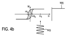
図4a及び図4bは、磁化特性を示し、すなわち、斯様な粒子の分散された粒子100の位置での磁場強度Hの関数として、その粒子100(図4a及び4bに示されない)の磁化Mの変化を示す。磁化Mが、磁場強度+Hcを越えては変化しない、また磁場強度−Hcより下でも変化しないことがわかり、これは、飽和磁化に到達したことを意味する。磁化Mは、値+Hcと−Hcとの間では飽和しない。
4a and 4b show the magnetization properties, ie the magnetization M of the particle 100 (not shown in FIGS. 4a and 4b) as a function of the magnetic field strength H at the position of the dispersed
図4aは、結果として生じる正弦波磁場H(t)(すなわち、「粒子100により見られる」)の絶対値が、磁気的に粒子100を飽和させるために必要とされる磁場強度より低い、すなわち他の磁場が活性でない場合の粒子100の位置での正弦波磁場H(t)の効果を例示する。この状況に対する粒子100の磁化は、磁場H(t)の周波数のリズムで、その飽和値間を往復運動する。磁化の結果的な時間変化は、図4aの右側に参照M(t)により示される。磁化は周期的にも変化し、斯様な粒子の磁化が周期的に反転することもわかる。
FIG. 4a shows that the absolute value of the resulting sinusoidal magnetic field H (t) (ie “seen by
曲線の中心でラインの点線部分は、正弦波磁場H(t)の磁場強度の関数として、磁化M(t)の近似的平均変化を示す。この中心線からの偏差として、磁化は、磁場Hが−HCから+HCへ増大するとき、僅かに右側へ拡がり、磁場Hが+HCから−HCへ減少するとき、僅かに左側へ拡がる。この既知の効果は、熱の発生のためのメカニズムの基礎をなすヒステリシス効果と呼ばれている。曲線の経路間に形成され、形状及びサイズが物質に依存しているヒステリシス表面領域は、磁化の変化の際の熱の発生に対する尺度である。 The dotted portion of the line at the center of the curve shows the approximate average change in magnetization M (t) as a function of the magnetic field strength of the sinusoidal magnetic field H (t). As a deviation from this centerline, the magnetization expands slightly to the right when the magnetic field H increases from -HC to + HC, and slightly expands to the left when the magnetic field H decreases from + HC to -HC. This known effect is called the hysteresis effect that underlies the mechanism for the generation of heat. The hysteresis surface region that is formed between the paths of the curves and that depends on the material in shape and size is a measure for the generation of heat during the change of magnetization.
図4bは、静磁場H1が重畳される正弦波磁場H(t)の効果を示す。磁化が飽和状態にあるので、それは正弦波磁場H(t)により実際に影響されない。磁化M(t)は、この領域で時間的に一定のままである。結果的に、磁場H(t)によって、磁化の状態の変化が生じない。 Figure 4b shows the effect of a sinusoidal magnetic field H (t) of the static magnetic field H 1 is superposed. Since the magnetization is in saturation, it is not actually affected by the sinusoidal magnetic field H (t). The magnetization M (t) remains constant in time in this region. As a result, the magnetic field H (t) does not change the magnetization state.
図5では、例えば国際特許公開公報WO2006/033047Aに記載されているMR撮像装置の通常のレイアウトが、ブロック図として例示されている。装置100は、静止及び均一な主磁場を生成するための主磁気コイル102のセットと、制御可能な強度を持つ付加的磁場を重畳し、選択された方向に勾配を持つ勾配磁場コイル103、104及び105の3つのセットとを有する。慣習的に、主磁場の方向はz方向に、それに垂直な2方向はx及びy方向にラベル付けされている。勾配磁場コイル103、104及び105は、電源111を介して付勢される。装置100は、更に、RFパルスをボディ107に放射するためのRF送信アンテナ106、例えば従来の直角位相ボディコイルを有する。直角位相コイルであるので、アンテナ106は、同じ振幅及び90°の位相差を持つRF信号により通常励起される2つの共振モードを持つ。本発明によると、アンテナ106は、アンテナ6の2つの異なる共振モードの位相及び振幅を制御するための受信/送信ユニット108に接続されている。受信/送信ユニット108は、RFパルスを生成し、変調するためのモジュレータ109に更に結合される。
In FIG. 5, for example, a normal layout of an MR imaging apparatus described in International Patent Publication No. WO2006 / 033047A is illustrated as a block diagram. The
図5に示されるように、RF送信アンテナ及び受信アンテナは、物理的に同じアンテナ106である。従って、送信/受信ユニット108は、放射されるべきRFパルスから受信信号を分離するように設けられている。受信MR信号は、復調器110に入力される。送信/受信ユニット108とモジュレータ109と勾配磁場コイル103、104及び105のための電源111とは、制御システム112により制御される。制御システム112は、ボディ300のアスペクト比に基づいて、アンテナ106に供給されるRF信号の位相及び振幅を制御する。制御システム112は、通常は、メモリ及びプログラム制御を持つマイクロコンピュータである。復調器110は、例えば視覚的表示装置115上で見えるようにできる画像へ受信エコー信号(磁気共鳴信号とも呼ばれる)を変換するためのデータ処理ユニット114、例えばコンピュータに結合される。
As shown in FIG. 5, the RF transmit antenna and the receive antenna are physically the
図6は、本発明による装置10の実施例のブロック図である。上述した磁気共鳴撮像及び磁性粒子撮像の一般的原理は、特に明記しない限り、同様にここで有効であって適用できる。
FIG. 6 is a block diagram of an embodiment of the
図5に示される装置10の実施例は、装置10の動作モードに所望される所望の磁場を生成するための一組の様々なコイルを有する。最初に、コイル及びMPIモードでのコイルの機能が説明される。
The embodiment of the
上述された選択磁場を生成するために、選択磁場(SF)コイル23のサブセット、好ましくは前記勾配磁場を生成するための一対のコイル素子を有する選択手段が供給される。選択手段は、更に、選択磁場信号発生器ユニット20を有する。好ましくは、選択磁場コイルのサブセット23の各コイル素子のための別々の生成器サブユニットが供給される。前記選択磁場信号発生器ユニット20は、制御可能な選択磁場電流源21(アンプを一般に含む)と、所望の方向に選択磁場の勾配強度を設定するために、それぞれの区域磁場コイル素子に選択磁場電流を供給するフィルタユニット22とを有する。好ましくは、DC電流が供給される。選択磁場コイル素子が対向コイルとして、例えば動作の領域の対向し合う側に配置される場合、対向コイルの選択磁場電流は、好ましくは反対の向きにある。
In order to generate the selection magnetic field described above, a selection means is provided having a subset of the selection field (SF) coils 23, preferably a pair of coil elements for generating the gradient field. The selection means further includes a selection magnetic field
選択磁場信号発生器ユニット20は、磁場強度の和及び選択磁場の全ての空間部分の勾配強度の和が既定のレベルに維持されるように、選択磁場電流生成を好ましくは制御する制御ユニット70により制御される。
The selected magnetic field
焦点磁場の生成のため、装置10は、焦点磁場(FF)コイル33a、33b、33cのサブセットを有する、好ましくは互いに反対の位置に配置された焦点磁場コイル素子の3つの対33a、33b、33cを有する焦点手段を更に有する。MPIの従来技術で一般に知られているように、前記焦点磁場は、動作の領域の空間内の位置を変化させるために一般に使われる。装置10は、更に、焦点磁場電流源31(好ましくは電流アンプを有する)と、焦点磁場を生成するために用いられるコイル33a、33b、33cの前記サブセットのそれぞれのコイルへ焦点磁場電流を供給するためのフィルタユニット32とを有する焦点磁場信号発生器ユニット30を有する。焦点磁場電流源31は、また、制御ユニット70により制御される。
For the generation of the focal field, the
駆動磁場の生成のために、装置10は、更に、駆動磁場(DF)コイル43a、43b、43cのサブセットを有する、好ましくは互いに反対の位置に配置された駆動磁場コイル素子の3つの対43a、43b、43cを有する駆動手段を有する。前記駆動磁場が、動作の領域内の2つの副ゾーンの空間内の位置を変化させるため前記時間的に変化する均一な磁場として概して使われるので、磁気材料の磁化が局所的に変化する。更に装置10は、駆動磁場信号発生器ユニット40、好ましくは駆動磁場コイル43a、43b、43cの前記設定されたサブセットの各コイル素子に対する別々の駆動磁場信号生成ユニットを有する。前記駆動磁場信号発生器ユニット40は、駆動磁場電流源41(好ましくは電流アンプを含む)と、それぞれの駆動磁場コイルへ駆動磁場電流を供給するためのフィルタユニット42とを有する。駆動磁場電流源41は、AC電流を生成するために構成され、また、制御ユニット70により制御される。
For the generation of the drive field, the
信号検出のために、受信手段54、特に受信コイルと、受信手段54により検出される信号を受信する信号受信ユニット50とが、供給される。信号受信ユニット50は、受信検出信号をフィルタリングするためのフィルタユニット51を有する。このフィルタリングの目的は、他の干渉信号から、2つの部分領域(301、302)の位置の変化により影響される検査領域の磁化により生じる測定値を分離することである。この目的のため、フィルタユニット51は、例えば、受信コイル54が動作される一時的周波数より小さい、すなわちこれらの一時的周波数より2倍小さい一時的周波数を持つ信号がフィルタユニット51を通らないように設計される。これら信号は、その後アンプユニット52を介してアナログ/デジタル変換器53(ADC)に送信される。アナログ/デジタル変換器53により生じるデジタル化された信号は(再構成手段とも呼ばれる)画像処理ユニット71に供給され、画像処理ユニット71は、画像処理ユニット71が制御ユニット70から得る、それぞれの信号の受信の間仮定される検査領域内の第1の磁場の第1の部分領域301のそれぞれの位置と、これらの信号とから磁性粒子の空間分布を再構成する。磁性粒子の再構成された空間分布は、制御手段70を介して最後にコンピュータ12へ送信され、コンピュータ12は空間分布をモニタ13上に表示する。このように、画像は、検査領域内の磁性粒子の分布を示して表示できる。
For signal detection, a receiving means 54, in particular a receiving coil, and a
更に、入力ユニット14、例えばキーボードが供給される。従って、ユーザは、最高解像度の所望の方向を設定でき、次にモニタ13上に動作の領域のそれぞれの画像を受ける。最高解像度が必要である重要な方向が、ユーザにより初めに設定された方向から逸脱する場合、ユーザは、改善された撮像解像度を持つ他の画像を作るために手動で方向を更に変化させることができる。この解像度改善プロセスは、また、制御ユニット70及びコンピュータ12により自動的に動作できる。本実施例の制御ユニット70は、ユーザによりスタート値として自動的に推定されるか又は設定される第1の方向に勾配磁場を設定する。その後、これにより受け取った画像の解像度が、コンピュータ12により比較されながら、最大になるまで、もう改善されなくなるまで、勾配磁場の方向が段階を追って変化される。従って、最も重要な方向が、可能性がある最高解像度を受信するためにそれぞれ自動的に適合され、見つけられる。
Furthermore, an
本発明によると、磁性粒子撮像のために一般に設計された図5に図示されるような装置は、磁気共鳴撮像のためにも使用可能であるように適合される。特に、MPI装置に供給される一組のコイルは、MRIのために必要とされる磁場が後述されるように生成できるように制御され、磁場生成電流を供給される。 In accordance with the present invention, an apparatus such as that illustrated in FIG. 5 that is generally designed for magnetic particle imaging is adapted to be usable for magnetic resonance imaging. In particular, a set of coils supplied to the MPI apparatus is controlled so that a magnetic field required for MRI can be generated as will be described later, and supplied with a magnetic field generating current.
前記一組のコイルは、特に、選択され可変の方向に実質的に均一な主磁場を生成可能であり、この目的のため好ましくは、選択磁場コイル23及び/又は焦点磁場コイル33a、33b、33cの一つ以上が使われる。前記一組のコイルは、更に、少なくとも2つ、好ましくは3つが直角の選択され可変の方向の勾配磁場を生成可能であり、この目的のため好ましくは、焦点磁場コイル33a、33b、33cが使われる。更に、以下に詳細に後述される様々な実施例が存在する、摂動するため動作の領域内の磁気スピンを励起するための励起手段が供給される。
Said set of coils is in particular capable of producing a main field which is substantially uniform in selected and variable directions, and for this purpose is preferably selected
サブセットのコイルは好ましくは互いに反対に配置されるコイル素子を有することに留意されたい。しかし、対のコイルの代わりに、所望の磁場を生成するため2つより多いコイル素子、例えば3つ又は4つのコイル素子が用いられることも可能である。更に、本発明の実施例によると、選択磁場コイル23及び焦点磁場コイル33a、33b、33cの全てのコイル素子は、所望の磁場の生成のため各コイル素子を個別に制御するために、別々の生成器サブユニット(共通の生成器ユニットの一部であってもよい)を具備する。駆動磁場コイル43a、43b、43cは統合受信コイルを持ち、焦点磁場コイル33a、33b、33cは選択磁場コイル23としても役立ち得る。
Note that the subset of coils preferably have coil elements arranged opposite to each other. However, instead of a pair of coils, it is also possible to use more than two coil elements, for example three or four coil elements, in order to generate the desired magnetic field. Furthermore, according to an embodiment of the present invention, all the coil elements of the
制御ユニット70は、MPIモード、MRIモード又は複合MPI/MRIモードで働くために様々な生成器ユニットを制御する、すなわち前記モード間を切換え(特にユーザ命令に応答して)、それぞれのコイルに対してそれぞれの制御信号を生成するために適合される。
The
本発明の態様によると、予め分極されたMRIシステムとしてMPIシステムを使用することが提案された。これは、数百ms間強い均一な磁場を付与することにより陽子が分極されることを意味する。RFパルス、空間符号化及び読み出しは、低めの磁場強度でなされる。斯様な予め分極されたMRIシステムは、Macovski A、Conolly Sによる「低コストMRIの新規なアプローチ」というタイトルのMagn.Reson.Med.1993年8月30日、(2):221―30という文献により説明されている。パルス化された電磁石を持つ予め分極されたMRI(PMRI)では、主磁場は、サンプルを分極するための高い磁場(Bp)とデータ収集のための均一で低い磁場(B0)との間の繰り返しである。このアーキテクチャは、分極磁場の高いSNRを低めの磁場の撮像利益と組み合わせる。しかしながら、スライスインターリーブ捕捉及び長手磁化記録は両方ともPMRIにおいて非効率的であるので、PMRIは、緩和増強での迅速な捕捉(RARE)(FSE、TSE)のような3D高速撮像技術でのボリューム測定撮像に対して高いSNR効率を達成できるだけである。 According to an aspect of the invention, it has been proposed to use an MPI system as a pre-polarized MRI system. This means that protons are polarized by applying a strong uniform magnetic field for several hundred ms. RF pulses, spatial encoding and readout are done with a lower magnetic field strength. Such a pre-polarized MRI system is disclosed in Magn., Entitled “New approach to low-cost MRI” by Makovski A, Conolly S. Reson. Med. August 30, 1993, (2): 221-30. In pre-polarized MRI (PMRI) with a pulsed electromagnet, the main magnetic field is between a high magnetic field (Bp) for polarizing the sample and a uniform low magnetic field (B 0 ) for data collection. It is repetition. This architecture combines a high polarization field SNR with a lower magnetic field imaging benefit. However, because slice-interleaved capture and longitudinal magnetization recording are both inefficient in PMRI, PMRI measures volume in 3D high-speed imaging techniques such as rapid capture with relaxation enhancement (RARE) (FSE, TSE). Only high SNR efficiency can be achieved for imaging.
MRIシステムとしてMPIシステムを使用する幾つかの態様がある。図7に図示されたような第1の実施例において、シムコイル83(並びに電流源81及びフィルタ82を含む対応シムコイル信号発生器ユニット80)が、MRI動作のために充分な均一性を持つ低い磁場強度磁場を生成するために加えられる。更に、RF送信器63、特に、RF送信コイル63が、励起のため必要なRF磁場を生成するために送信信号生成器ユニット60(送信アンプ61及びフィルタ62を含む)に結合されて加えられる。システムは、約50mTで動作する。
There are several ways to use the MPI system as the MRI system. In a first embodiment as illustrated in FIG. 7, a shim coil 83 (and a corresponding shim coil
図6に示すように、第2の実施例において、送信信号生成器ユニット60は、受信器手段54、すなわち必要なRF磁場を生成するための受信コイルに結合される。
As shown in FIG. 6, in a second embodiment, the transmit
第3の実施例では、シムコイル83及びシムコイル信号発生器ユニット80だけが加えられる(しかし、送信信号生成器ユニット60及びRF送信機63は加えられない)。よって、利用可能な受信周波数でRFB1磁場がない。RFパルスは、駆動磁場周波数がラーモア周波数であるレベルまで主要な磁場を繰り返し下げることにより生成される。その後で、受信が、例えば50mTまで逓減された後になされる。代わりに、RFパルスは、0磁場まで主磁場を減少させて、その後、異なる磁化方向を使用して主要な磁場を増大させることにより生成される。特に、主磁場は、現在の磁化方向と一致せず、主磁場を減少させるとき、0値に到達する直前に存在した主磁場の方向に概して一致する方向に再び生成される。
In the third embodiment, only shim
第4の実施例では、何れのシムコイル83(及びシムコイル信号発生器ユニット80)又は何れの送信信号生成器ユニット60及びRF送信機63も加えられない。均一な磁場のための自明の解決策は、0磁場である。0磁場で、スピンは、それらの初期の配向のままである。ここで、均一な磁場が加えられる場合、異なる方向を示して、磁化は摂動動きを実施し始めるだろう。それ故、RFパルスが付与された。記録のために、主要な磁場は、MPI記録システムが有効である値まで逓減される。
In the fourth embodiment, no shim coil 83 (and shim coil signal generator unit 80) or any transmission
この種のMPIは、シーケンスの幾らかの適合を必要とする。例えば、スピンエコーは、磁場方向の反転だけである。ボリューム選択のために、強い勾配を維持しながら、磁場自由点(FFP)は、無限遠から視野の所望の磁場の中心まで移動される。そのとき、勾配はゼロまで減少し、RFシーケンスが付与される。 This type of MPI requires some adaptation of the sequence. For example, spin echo is only reversal of the magnetic field direction. For volume selection, the magnetic field free point (FFP) is moved from infinity to the center of the desired magnetic field in the field of view while maintaining a strong gradient. At that time, the slope is reduced to zero and an RF sequence is applied.
従来のMRIで可能ではない、提案されたMPI/MRIの組合せにおける特徴がある。例えば、磁化方向は、記録システムが最も効率的である方向に向けられる。記録の間、B0磁場を曲げることも可能である。これは、利用可能な3つの磁化方向があるので、特に(例えばK.P.PruessmannらによるSENSE、MAGMA6(1):87、1998の「高速MRIのための感度符号化」に説明される従来のMRIではSENSEとも呼ばれる)感度符号化に対して、パラレル撮像において、より多くの自由度を与える。 There are features in the proposed MPI / MRI combination that are not possible with conventional MRI. For example, the magnetization direction is oriented in the direction in which the recording system is most efficient. During recording, it is also possible to bend the B 0 magnetic field. This is especially true as it is described in “Sensitivity coding for high-speed MRI” (eg, SENSE, MAGMA 6 (1): 87, 1998 by K. P. Pruesmann et al.) Because there are three magnetization directions available. (In MRI, also called SENSE), it gives more freedom in parallel imaging for sensitivity coding.
主磁場強度を変える可能性は、例えば窒素撮像のためB0依存のT1に依存して、コントラストの使用を可能にする。スキャナは、過分極化された希ガスの撮像を可能にする本質的に多核システムである。常磁性インプラントは画像品質に軽微な影響を及ぼし、スキャンはインプラントの最小加熱でなされる。よって、従来のMRIシステムに入ることができないある患者は、このスキャナで走査され得る。特に、ステントの内部を見ることが可能である。 Possibility of changing the main magnetic field strength, for example for nitrogen imaging depending on the B 0 dependent T1, allows the use of contrast. The scanner is essentially a multinuclear system that allows imaging of hyperpolarized noble gases. Paramagnetic implants have a minor effect on image quality and scanning is done with minimal heating of the implant. Thus, some patients who are unable to enter a conventional MRI system can be scanned with this scanner. In particular, it is possible to see the inside of the stent.
B0磁場の任意の方向は、組織の導電率の明白な決定のような他のコントラストを許容する。B0が低くできるので、導電率は、組織変化が最も病変を反映する1MHzより低い周波数に対して撮像され得る。その上、周波数依存の導電率が記録できる。 Any direction of the B 0 field allows other contrasts such as an unambiguous determination of tissue conductivity. Since B 0 can be lowered, the conductivity can be imaged for frequencies below 1 MHz where the tissue change most reflects the lesion. In addition, frequency dependent conductivity can be recorded.
他の特定のアプリケーションについて説明する前に、「解剖学的基準」の規定のためのシナリオが説明される。MPIは、磁性粒子の分布を撮像する。これらのデータを解釈するために、根拠をなす解剖学的構造の画像を参照することは有用である。この情報を得る多くのやり方がある。最も単純なやり方は、両方のモダリティで識別できるマーカーを使用して、MPI画像に他のモダリティの画像を重ねることである。MPIスキャナの隣にCTシステムを配置することも可能である。両方のモダリティのため同じ患者サポート台(「共有テーブル」と呼ばれる)を利用するとき、画像の位置合せは単純になる。それにもかかわらず、融合された画像の不確定度をおそらく導くので、幾らかの融合が、まだ必要である。また、追加の撮像システムは、より高いコスト及び患者の処置でのより多くの労力を意味する。 Before describing other specific applications, scenarios for the definition of “anatomical criteria” are described. MPI images the distribution of magnetic particles. To interpret these data, it is useful to refer to the underlying anatomical image. There are many ways to get this information. The simplest approach is to overlay images of other modalities on the MPI image, using markers that are distinguishable by both modalities. It is also possible to place a CT system next to the MPI scanner. Image registration is simplified when utilizing the same patient support platform (referred to as a “shared table”) for both modalities. Nevertheless, some fusion is still necessary as it will probably lead to uncertainty in the fused image. The additional imaging system also means higher costs and more effort in patient treatment.
従って、MPIと解剖学的基準画像との固有の組合せは、有効にみえる。斯様な組合せの一つは、技術的に可能にみえる磁気共鳴撮像との組み合わせである。MPI及びMRI両方が、高磁場を使用し、弱い振動磁場を記録する。磁場ジオメトリ及び周波数は一致しないが、適度な技術的労力で、MPI及びMRI両方に役立つ部品がデザインされる。例えば、MPIの選択磁場が電磁石により生成される場合、1つのコイルの逆電流は陽子を分極させるために適している均一な磁場を作る。MRIのための磁場強度は、抵抗コイルのため0.5T及び超電導コイルのため1T以上に達する。 Thus, the unique combination of MPI and anatomical reference image appears to be effective. One such combination is a combination with magnetic resonance imaging that appears technically feasible. Both MPI and MRI use high magnetic fields and record weak oscillating magnetic fields. Magnetic field geometries and frequencies do not match, but with moderate technical effort, parts useful for both MPI and MRI are designed. For example, if the selected magnetic field of MPI is generated by an electromagnet, the reverse current of one coil creates a uniform magnetic field that is suitable for polarizing protons. The magnetic field strength for MRI reaches 0.5T for the resistance coil and 1T or more for the superconducting coil.
固有のMPI/MRI組合せを問題とする様々な影響がある。MRIに対して、磁場は非常に均一なことを必要とするが、斯様なコイルアセンブリが選択磁場生成に対してあまり効率的でないので、一つのコイルの電流方向を単に変えることは、通常、充分な均一性を磁場に提供しない。MPIシステムは、RFB1磁場のための送信器及び数十MHzの高さの周波数のための記録システムを含まない。その上、MPI駆動及び記録コイルは、MRIB1コイルの追加を困難にする低いMHz範囲の自己共振を持つ。 There are a variety of effects that make specific MPI / MRI combinations problematic. For MRI, the magnetic field needs to be very uniform, but simply changing the current direction of one coil is usually as such coil assemblies are not very efficient for selective magnetic field generation. Does not provide sufficient uniformity for the magnetic field. The MPI system does not include a transmitter for RFB 1 magnetic field and a recording system for frequencies as high as tens of MHz. In addition, the MPI drive and recording coils have a low MHz range self-resonance that makes adding MRIB 1 coils difficult.
これらの技術的なチャレンジに対する一つの解決策は、Macovski A、Conolly Sによる「低コストMRIの新規なアプローチ」というタイトルのMagn.Reson.Med.1993年8月30日、(2):221―30という文献に説明されているような、磁場循環又は予め分極されたMRIシステムを構成することである。斯様なシステムでは、強いが、必ずしもあまり均一ではない磁場が、陽子を分極するために数百ミリ秒間付与される。分極パルスの後、磁場は、RFパルスが付与される非常に低い値まで減少する。MRIでは、磁場均一性は、1Tスキャナのため10ppmであるが、1mTスキャナのためには1%であるおよそ10μTμ0 −1であることを必要とする。斯様な値は、選択磁場コイルの電流方向を変えることにより到達できる。 One solution to these technical challenges is that of Macnski A, Conolly S, entitled “New Approach to Low Cost MRI”, Magn. Reson. Med. Aug. 30, 1993, (2): constructing a magnetic circulation or pre-polarized MRI system as described in the literature 221-130. In such a system, a strong but not necessarily very uniform magnetic field is applied for hundreds of milliseconds to polarize the protons. After the polarization pulse, the magnetic field decreases to a very low value at which the RF pulse is applied. In MRI, the magnetic field homogeneity is 10 ppm for a 1T scanner, but needs to be approximately 10 μTμ 0 −1 which is 1% for a 1 mT scanner. Such a value can be reached by changing the current direction of the selected magnetic field coil.
斯様な低い磁場まで行って、RFパルスは、駆動磁場コイルを使用して付与できる。0.6mTの陽子のラーモア周波数は、25kHz、すなわち現在使用されるMPI駆動磁場周波数である。MPIスキャナの駆動磁場振幅は、明らかにMRIのための必要な振幅を超えている。RFパルスのための駆動磁場の代替例は、焦点磁場である。それは、最高約1kHzの周波数成分を含む。従って、RFパルスを付与するとき、B0磁場は更により低くなければならない。焦点磁場振幅があまり高いので、RFパルスが以下のように説明される。i)強いB0磁場を使用して陽子を分極する(選択磁場コイルを使用して、最終的には焦点磁場コイルの一部及び/又は利用できるならば追加のシムコイルを使用して)。ii)磁場強度を0まで減少させる。iii)陽子分極と同一でない方向を使用して磁場値を増大させる(これは、「RFパルス」、すなわち摂動の原因である)。磁化方向は、例えば90°好ましくは回転する。iv)信号記録のため好都合のラーモア周波数(例えば1MHz)に到達するまで磁場を逓増させる。 Proceeding to such a low magnetic field, RF pulses can be applied using a drive field coil. The 0.6 mT proton Larmor frequency is 25 kHz, the currently used MPI drive magnetic field frequency. The drive field amplitude of the MPI scanner clearly exceeds the amplitude required for MRI. An alternative to the driving field for the RF pulse is the focal field. It contains frequency components up to about 1 kHz. Thus, when granting RF pulse, B 0 field must be even lower than. Since the focal field amplitude is too high, the RF pulse is described as follows. i) Polarize protons using a strong B 0 field (using a selective field coil and eventually using part of the focal field coil and / or an additional shim coil if available). ii) Decrease the magnetic field strength to zero. iii) Increase the magnetic field value using a direction that is not the same as the proton polarization (this is the cause of the “RF pulse” or perturbation). The magnetization direction is preferably rotated by 90 °, for example. iv) Increasing the magnetic field until a convenient Larmor frequency (eg 1 MHz) is reached for signal recording.
この方法を使用するスピンエコーは、単純な磁場反転である。 Spin echo using this method is a simple magnetic field reversal.
予め分極されたMRIは、MPIの解剖学的基準のために確かに充分である。幾つかの選択されたアプリケーションのために、それは、MRIの従来のやり方より優れてさえいる。インプラントを持つ患者のために、インプラントが強磁性でない限り、予め分極されたMRIは、近接インプラント撮像を可能にする。MPI/MRI組合せが、更に低い周波数でさえ動作可能であり、従って、それは金属ステント内部での撮像も可能であり、おそらく再狭窄を評価できる。磁場の繰り返しは、従来のMRIではアクセス可能でない、コントラストを可能にする。例えば、組織の蛋白質含有量は、磁場依存的なT1緩和時間を使用して撮像できる。 Pre-polarized MRI is certainly sufficient for MPI anatomical criteria. For some selected applications it is even better than the traditional way of MRI. For patients with implants, pre-polarized MRI allows proximity implant imaging unless the implant is ferromagnetic. The MPI / MRI combination can operate even at lower frequencies, so it can also be imaged inside a metal stent, possibly assessing restenosis. The repetition of the magnetic field allows contrast that is not accessible with conventional MRI. For example, the protein content of a tissue can be imaged using a magnetic field dependent T1 relaxation time.
好適には、MPI及びMRI信号取得は、複合MPI/MRIモードでなされ得る。特に、動作の領域内のある位置でMPI検出信号を得ると共に、陽子は他の位置で(例えば最高0.2Tまでの磁場強度を持って)分極できる。分極のステップは、予め分極されたMRIの時間にクリティカルなステップである。よって、例えば、MPIの測定時間のほぼ10%がMRIのために使用できるが、それにもかかわらず、MRIデータ収集のために通常必要とされる時間の100%で取得されるデータで得られるMR画像と同じ品質を持つMR画像が得られる。陽子の分極は、潅流画像を得ることができるこの位置に血流により移送されるので、MPI信号が得られる同じ位置でMR信号を測定することも有効であり得る。 Preferably, MPI and MRI signal acquisition can be done in combined MPI / MRI mode. In particular, while obtaining an MPI detection signal at one location within the region of motion, the proton can be polarized at another location (eg, with a magnetic field strength of up to 0.2 T). The polarization step is a critical step in the pre-polarized MRI time. Thus, for example, approximately 10% of the MPI measurement time can be used for MRI, but nevertheless MR obtained with data acquired in 100% of the time normally required for MRI data collection An MR image having the same quality as the image is obtained. Since proton polarization is transferred by the bloodstream to this location where a perfusion image can be obtained, it may also be useful to measure the MR signal at the same location where an MPI signal is obtained.
MPIシステムの焦点磁場が任意の方向を示せるので、予め分極されたMPI/MRIの組合せは、任意にB0を向けさせるための能力を持つ。これは、記録コイルの効果的な利用を可能にする。その上、これは、異方性の組織の電気的インピーダンス測定のためMRIを使用して電流マッピングの課題を解決できる。従来のMRIでは、1つの磁場成分だけが、低周波電流密度撮像の場合に測定できる。位相シフトは、低周波で患者を流れる電流を付与することにより生成される。これは、B0方向の磁場成分を感知するだけである。従って、十分な電流密度を再構成することは不可能である。高周波電流密度撮像で、2つの磁場成分が検出できる。この技術では、電流による磁場は、MRIのRF磁場として作用する。通常、B1磁場による患者内の渦電流が利用される。電流密度の十分な再構成は、依然不可能である。 Since it can show the direction focus magnetic field in any MPI system, a combination of pre-polarized MPI / MRI has the ability to make arbitrarily toward the B 0. This allows for effective use of the recording coil. Moreover, this can solve the current mapping problem using MRI for measuring the electrical impedance of anisotropic tissue. In conventional MRI, only one magnetic field component can be measured in the case of low frequency current density imaging. The phase shift is generated by applying a current through the patient at a low frequency. This is simply to sense the B 0 direction of the magnetic field component. Therefore, it is impossible to reconstruct a sufficient current density. Two magnetic field components can be detected by high-frequency current density imaging. In this technique, the magnetic field generated by the current acts as an MRI RF magnetic field. Usually, eddy currents in the patient due to the B 1 magnetic field are used. Full reconstruction of the current density is still impossible.
提案された予め分極されたMPI/MRIの組合せで、全ての磁場成分が測定できる。これは、組織導電率の異方性を再構成可能にする。その上、ラーモア―周波数を選択する能力は、患者への最小の影響が予想されるが、依然強い組織特定のコントラストが予想される電流注入周波数、すなわち100kHzでの使用を可能にする。 With the proposed prepolarized MPI / MRI combination, all magnetic field components can be measured. This makes the tissue conductivity anisotropy reconfigurable. In addition, the ability to select the Larmor frequency allows for use at the current injection frequency, ie 100 kHz, where minimal impact on the patient is expected but still a strong tissue specific contrast is expected.
斯様なMPI/MRIシステムが磁場強度を急速に変える能力を持ち、非常に広い帯域の受信システムを具備するので、多核MRIに対してもかなり適している。陽子以外の他の核子が比較的弱い信号を作るので、MPI/MRIシステムのおそらく低いB0磁場強度は、理想的ではない。他方、肺撮像のためキセノン129Xe及びヘリウム3Heを使用し、代謝撮像のため炭素13Cを使用するMRIの過分極化された技術がある。最後に、磁化率偽信号は、低い読み出し磁場強度でそれほど厳しくないので、改善された品質を持つ陽子肺画像が期待できる。 Such an MPI / MRI system has the ability to rapidly change the magnetic field strength and has a very wide band receiving system, so it is also well suited for multinuclear MRI. The possibly low B0 field strength of the MPI / MRI system is not ideal because other nucleons other than protons produce a relatively weak signal. On the other hand, there is an MRI hyperpolarized technique that uses xenon 129 Xe and helium 3 He for lung imaging and carbon 13 C for metabolic imaging. Finally, the susceptibility false signal is not so severe at low readout magnetic field strength, so a proton lung image with improved quality can be expected.
要約すると、磁性粒子撮像は、速いトレーサ動特性の撮像を可能にするが、自然の組織コントラストがない。MRIとの組合せは、この課題を解決する。しかしながら、MPI及びMRIのコイルジオメトリーは著しく異なるので、直接の使用を非実用的にする。本発明の一態様によると、これらの課題を克服するために、予め分極されるMRIを使用することが提案される。更に、最小の追加ハードウェアでMRI撮像を達成するための方法及び装置が提案される。 In summary, magnetic particle imaging allows for fast tracer dynamic imaging, but lacks natural tissue contrast. Combination with MRI solves this problem. However, the coil geometry of MPI and MRI is significantly different, making direct use impractical. According to one aspect of the present invention, it is proposed to use pre-polarized MRI to overcome these problems. Furthermore, a method and apparatus for achieving MRI imaging with minimal additional hardware is proposed.
本発明は図面及び前述の説明で例示され詳述されたが、斯様な図面及び説明は、図示的又は例示的であって、限定的とはみなされず、本発明は、開示された実施例に限定されない。図面、詳細な説明及び添付の請求の範囲の学習から、開示された実施例に対する他の変形例が、請求された本発明を実施する際に、当業者により理解できるし、遂行できる。 While the invention has been illustrated and described in detail in the drawings and foregoing description, such illustration and description are to be considered illustrative or exemplary and not restrictive; the invention is not limited to the disclosed embodiments; It is not limited to. From studying the drawings, detailed description, and appended claims, other variations to the disclosed embodiments can be understood and carried out by those skilled in the art in practicing the claimed invention.
請求項において、「を有する」という語は他の要素又はステップを除外しないし、不定冠詞「a」、又は「an」は複数を除外しない。単一の要素又は他のユニットにより、請求項で再引用される幾つかのアイテムの機能を成し遂げてもよい。特定の手段が異なる従属請求項で相互に再引用されているという単なる事実は、これら手段の組合せが好適に使用できないことを示すものではない。 In the claims, the word “comprising” does not exclude other elements or steps, and the indefinite article “a” or “an” does not exclude a plurality. The functions of several items recited in the claims may be accomplished by a single element or other unit. The mere fact that certain measures are mutually recitation in different dependent claims does not indicate that a combination of these measures cannot be used to advantage.
請求項内の参照符号は何れも、範囲を限定するものとして解釈されてはならない。 Any reference signs in the claims should not be construed as limiting the scope.
Claims (11)
磁性粒子撮像モードと磁気共鳴撮像モードとの間で前記装置を切換えるための制御手段と、前記磁性粒子撮像モードにおいて、低い磁場強度を持つ第1の副ゾーン及び高い磁場強度を持つ第2の副ゾーンが前記動作の領域内に形成されるように、磁場強度の空間内にパターンを持つ静止の勾配磁場を生成するための第1のサブセットのコイルと、前記磁性粒子撮像モードにおいて、前記動作の領域の空間内の位置を変えるための時間的に変化する均一の磁場を生成するための第2のサブセットのコイルと、前記磁性粒子撮像モードにおいて、磁気材料の磁化が局所的に変化するように、前記動作の領域の2つの前記副ゾーンの空間内の位置を変えるため時間的に変化する均一の磁場を生成するための第3のサブセットのコイルとを有し、第1のサブセットのコイル及び/又は第2のサブセットのコイルは、前記磁気共鳴撮像モードにおいて、選択され可変の方向の実質的に均一な主磁場を生成し、第2のサブセットのコイルは、前記磁気共鳴撮像モードにおいて、少なくとも二つの選択され可変の方向の勾配磁場を生成し、前記装置は、前記磁気共鳴撮像モードにおいて、摂動するために前記動作の領域内の磁気スピンを励起させる励起手段であって、前記磁気共鳴撮像モードにおいて、RF送信信号を生成するため他のRF送信コイルなしに実行される当該励起手段と、前記磁性粒子撮像モードにおいて第1及び第2の副ゾーンの空間内の位置の変化により影響される前記動作の領域内の磁化に依存して検出信号を、前記磁気共鳴撮像モードにおいて磁気共鳴信号を選択的に得るための受信手段と、磁場生成信号を生成し、一組のコイルに供給するための信号生成手段と、前記検出信号及び前記磁気共鳴信号を処理するための処理手段とを有し、前記制御手段は、前記磁性粒子撮像モード及び前記磁気共鳴撮像モードを含むそれぞれのモードにおいて要求される磁場生成信号を生成し、前記一組のコイルに供給するための前記信号生成手段を制御する、装置。 An apparatus for influencing and / or detecting magnetic particles in a region of motion and / or magnetic resonance imaging of an inspection object in the region of motion, the device comprising:
Control means for switching the device between a magnetic particle imaging mode and a magnetic resonance imaging mode; a first subzone having a low magnetic field strength and a second subzone having a high magnetic field strength in the magnetic particle imaging mode; In the magnetic particle imaging mode, a first subset of coils for generating a stationary gradient magnetic field having a pattern in a field of magnetic field strength such that a zone is formed in the region of motion, In a second subset of coils for generating a time-varying uniform magnetic field for changing the position of the region in space, and in the magnetic particle imaging mode, the magnetization of the magnetic material changes locally. A third subset of coils for generating a time-varying uniform magnetic field to change the position in space of the two sub-zones of the region of operation, A subset of coils and / or a second subset of coils generates a substantially uniform main magnetic field in a selected and variable direction in the magnetic resonance imaging mode, and a second subset of coils is the magnetic resonance imaging. Generating at least two selected and variable directional gradient magnetic fields in the mode, wherein the apparatus is an excitation means for exciting magnetic spins in the region of operation to perturb in the magnetic resonance imaging mode; In the magnetic resonance imaging mode, the excitation means executed without another RF transmission coil to generate an RF transmission signal, and the position change in the space of the first and second sub-zones in the magnetic particle imaging mode detection signal depending on the magnetization in the region of the operation being affected to obtain the magnetic resonance signals selectively in the magnetic resonance imaging mode by Receiving means for generating a signal, generating a magnetic field generation signal and supplying it to a set of coils, and processing means for processing the detection signal and the magnetic resonance signal, the control means Is a device for generating a magnetic field generation signal required in each mode including the magnetic particle imaging mode and the magnetic resonance imaging mode, and controlling the signal generation means for supplying the magnetic field generation signal to the set of coils.
磁性粒子撮像モードと磁気共鳴撮像モードとの間で前記装置を切換えるステップと、前記磁性粒子撮像モードにおいて、i)低い磁場強度を持つ第1の副ゾーン及び高い磁場強度を持つ第2の副ゾーンが前記動作の領域内に形成されるように、磁場強度の空間内にパターンを持つ静止の勾配磁場と、ii)前記動作の領域の空間内の位置を変えるための時間的に変化する均一の磁場と、iii)磁気材料の磁化が局所的に変化するように、前記動作の領域の2つの前記副ゾーンの空間内の位置を変えるため時間的に変化する均一の磁場とを生成するステップと、前記磁気共鳴撮像モードにおいて、iv)選択され可変の方向の実質的に均一な主磁場と、v)少なくとも二つの選択され可変の方向の勾配磁場とを生成するステップと、vi)前記磁気共鳴撮像モードにおいて、RF送信信号を生成するため別個のRF送信コイルを使用することなしに摂動するために前記動作の領域内の磁気スピンを励起させるステップと、前記磁性粒子撮像モードにおいて第1及び第2の副ゾーンの空間内の位置の変化により影響される前記動作の領域内の磁化に依存して検出信号を、前記磁気共鳴撮像モードにおいて磁気共鳴信号を選択的に得るステップと、前記検出信号及び前記磁気共鳴信号を処理するステップを有する、方法。 A method for influencing and / or detecting magnetic particles in a region of motion and / or magnetic resonance imaging of an object to be examined in the region of motion with a device comprising:
Switching the apparatus between a magnetic particle imaging mode and a magnetic resonance imaging mode; in the magnetic particle imaging mode, i) a first subzone having a low magnetic field strength and a second subzone having a high magnetic field strength A stationary gradient magnetic field having a pattern in the field of magnetic field strength, and ii) a time-varying uniform for changing the position of the region of motion in space. Generating a magnetic field and iii) a time-varying uniform magnetic field to change the position in space of the two sub-zones of the region of operation so that the magnetization of the magnetic material changes locally. In said magnetic resonance imaging mode, iv) generating a substantially uniform main field in a selected variable direction; v) generating at least two selected variable direction gradient magnetic fields; vi) before In magnetic resonance imaging mode, a step of exciting magnetic spins of said operation in the area in order to perturb without using a separate RF transmitter coil for generating an RF transmission signal, in the magnetic particle imaging mode first And selectively obtaining a detection signal in dependence on the magnetization in the region of operation affected by a change in position in space of the second subzone, and a magnetic resonance signal in the magnetic resonance imaging mode; Processing the detection signal and the magnetic resonance signal.
A computer program comprising program code means for causing a computer to control the apparatus of claim 1 to carry out the steps of the method of claim 9 when the computer program is executed on a computer.
Applications Claiming Priority (3)
| Application Number | Priority Date | Filing Date | Title |
|---|---|---|---|
| EP09159257.6 | 2009-04-30 | ||
| EP09159257 | 2009-04-30 | ||
| PCT/IB2010/051790 WO2010125510A1 (en) | 2009-04-30 | 2010-04-23 | Arrangement and method for influencing and/or detecting magnetic particles and for magnetic resonance imaging |
Publications (3)
| Publication Number | Publication Date |
|---|---|
| JP2012525193A JP2012525193A (en) | 2012-10-22 |
| JP2012525193A5 JP2012525193A5 (en) | 2013-06-06 |
| JP5662420B2 true JP5662420B2 (en) | 2015-01-28 |
Family
ID=42344730
Family Applications (1)
| Application Number | Title | Priority Date | Filing Date |
|---|---|---|---|
| JP2012507867A Expired - Fee Related JP5662420B2 (en) | 2009-04-30 | 2010-04-23 | Apparatus and method for magnetic resonance imaging by influencing and / or detecting magnetic particles |
Country Status (6)
| Country | Link |
|---|---|
| US (1) | US8666473B2 (en) |
| EP (1) | EP2425268B1 (en) |
| JP (1) | JP5662420B2 (en) |
| CN (1) | CN102414572B (en) |
| RU (1) | RU2519517C2 (en) |
| WO (1) | WO2010125510A1 (en) |
Families Citing this family (32)
| Publication number | Priority date | Publication date | Assignee | Title |
|---|---|---|---|---|
| WO2011021165A1 (en) * | 2009-08-21 | 2011-02-24 | Koninklijke Philips Electronics N.V. | Apparatus and method for generating and moving a magnetic field having a field free line |
| US8970217B1 (en) | 2010-04-14 | 2015-03-03 | Hypres, Inc. | System and method for noise reduction in magnetic resonance imaging |
| CN103260507B (en) * | 2010-12-10 | 2016-04-27 | 皇家飞利浦电子股份有限公司 | For affecting and/or detect equipment and the method for magnetic-particle |
| US20150301139A1 (en) * | 2012-02-08 | 2015-10-22 | Anatech Advanced Nmr Alorithms Technologies Ltd. | Method and system for inspection of composite material components |
| CN102749598B (en) * | 2012-07-27 | 2015-04-08 | 中国计量学院 | Magnetic resonance radio frequency coil based on fractal alternating impedance micro-strip |
| WO2014031985A1 (en) | 2012-08-24 | 2014-02-27 | The Trustees Of Dartmouth College | Method and apparatus for magnetic susceptibility tomography, magnetoencephalography, and taggant or contrast agent detection |
| DE102012221838B3 (en) * | 2012-11-29 | 2014-04-30 | Bruker Biospin Mri Gmbh | Device for the sequential examination of a measurement object by means of the methods MPI and MRI |
| US20170003365A1 (en) * | 2014-03-14 | 2017-01-05 | The General Hospital Corporation | System and method for magnetic resonance fingerprinting |
| US9964608B2 (en) | 2014-05-07 | 2018-05-08 | The Trustees Of Dartmouth College | Method and apparatus for nonlinear susceptibility magnitude imaging of magnetic nanoparticles |
| WO2016058842A1 (en) * | 2014-10-17 | 2016-04-21 | Koninklijke Philips N.V. | Spatially resolved metal detector |
| KR20170082600A (en) * | 2014-11-11 | 2017-07-14 | 하이퍼파인 리서치, 인크. | Pulse sequences for low field magnetic resonance |
| KR101623129B1 (en) | 2015-06-25 | 2016-05-23 | 서울대학교 산학협력단 | Method of obtaining bio-image using resonance of magnetic nano particle |
| KR101623116B1 (en) | 2015-06-25 | 2016-05-23 | 서울대학교 산학협력단 | Method of obtaining image |
| AU2017236982A1 (en) | 2016-03-22 | 2018-10-04 | Hyperfine Operations, Inc. | Methods and apparatus for magnetic field shimming |
| WO2018055150A1 (en) | 2016-09-26 | 2018-03-29 | Nanoscale Biomagnetics S.L. | Device for generating a magnetic field |
| EP3669201B1 (en) * | 2017-08-16 | 2023-10-25 | The Regents of the University of California | Pulsed magnetic particle imaging systems and methods |
| CN107907842B (en) * | 2017-11-24 | 2020-10-02 | 武汉中科牛津波谱技术有限公司 | Detection method of extremely weak magnetic material |
| EP3546967B1 (en) * | 2018-03-26 | 2022-11-23 | Siemens Healthcare GmbH | Local coil matrix and method for imaging |
| TW202015621A (en) | 2018-07-19 | 2020-05-01 | 美商超精細研究股份有限公司 | Methods and apparatus for patient positioning in magnetic resonance imaging |
| TW202012951A (en) | 2018-07-31 | 2020-04-01 | 美商超精細研究股份有限公司 | Low-field diffusion weighted imaging |
| CN111820895B (en) * | 2019-04-18 | 2024-05-03 | 深圳先进技术研究院 | Magnetic nanoparticle imaging device and debugging and constructing method of scanner in magnetic nanoparticle imaging device |
| CN110180076B (en) * | 2019-05-31 | 2022-03-01 | 重庆科技学院 | Spatial magnetic particle regulation and control aggregation system |
| US20210068699A1 (en) * | 2019-09-06 | 2021-03-11 | GE Precision Healthcare LLC | Methods and systems for mri patient prescreening |
| US11510588B2 (en) | 2019-11-27 | 2022-11-29 | Hyperfine Operations, Inc. | Techniques for noise suppression in an environment of a magnetic resonance imaging system |
| TR202007444A1 (en) | 2020-05-13 | 2021-11-22 | Aselsan Elektronik Sanayi Ve Tic A S | AN EQUIPMENT THAT PROVIDES BOTH MAGNETIC PARTICLE IMAGING AND MAGNETIC RESONANCE IMAGING AND A DEVICE CONTAINING THIS EQUIPMENT |
| KR102508516B1 (en) * | 2020-10-30 | 2023-03-09 | 광주과학기술원 | Open Magnetic Particle Imaging Apparatus |
| FR3119891B1 (en) * | 2021-02-12 | 2023-11-17 | Commissariat Energie Atomique | Device for characterizing a corium bath formed or being formed in a nuclear reactor |
| JP7523675B2 (en) | 2021-04-13 | 2024-07-26 | 三菱電機株式会社 | Magnetic particle imaging device |
| DE112021007259T5 (en) * | 2021-05-18 | 2023-12-28 | Mitsubishi Electric Corporation | Device for recognizing biological information and method for recognizing biological information |
| CN115067918B (en) * | 2022-08-18 | 2022-12-23 | 沈阳工业大学 | FFL-based high-definition real-time imaging device, system and method |
| CN115054222B (en) * | 2022-08-18 | 2022-12-27 | 沈阳工业大学 | Mechanical scanning large-space magnetic particle imaging device, imaging system and imaging method |
| CN117547242B (en) * | 2024-01-12 | 2024-05-14 | 杭州永川科技有限公司 | Magnetic induction tomography apparatus |
Family Cites Families (15)
| Publication number | Priority date | Publication date | Assignee | Title |
|---|---|---|---|---|
| US4680551A (en) * | 1985-10-07 | 1987-07-14 | General Electric Company | Method for homogenizing a static magnetic field over an arbitrary volume |
| FR2621392A1 (en) * | 1988-09-30 | 1989-04-07 | Gen Electric Cgr | LOW FIELD NMR MACHINE WITH DYNAMIC POLARIZATION |
| GB9007408D0 (en) * | 1990-04-02 | 1990-05-30 | Nycomed As | Compositions |
| GB9120508D0 (en) * | 1991-09-26 | 1991-11-06 | Nycomed As | Diagnostic agents |
| DE10151778A1 (en) | 2001-10-19 | 2003-05-08 | Philips Corp Intellectual Pty | Method for determining the spatial distribution of magnetic particles |
| US6798202B2 (en) * | 2001-11-23 | 2004-09-28 | Koninklijke Philips Electronics N.V. | Planar radio frequency coil for open magnetic resonance imaging systems |
| DE10202986A1 (en) * | 2002-01-26 | 2003-07-31 | Philips Intellectual Property | Coil system for an MR apparatus and MR apparatus with such a coil system |
| EP1615694B1 (en) * | 2003-04-15 | 2017-06-14 | Philips Intellectual Property & Standards GmbH | Method and apparatus for influencing magnetic particles |
| JP4450610B2 (en) * | 2003-12-03 | 2010-04-14 | 株式会社日立メディコ | A magnetic resonance imaging apparatus having diagnostic and therapeutic functions using a high gradient magnetic field. |
| US7496454B2 (en) * | 2004-07-19 | 2009-02-24 | University Of Virginia Patent Foundation | High mast inspection system, equipment and method |
| JP5085327B2 (en) | 2004-09-24 | 2012-11-28 | コーニンクレッカ フィリップス エレクトロニクス エヌ ヴィ | Magnetic resonance device and method |
| CN100486521C (en) * | 2006-07-19 | 2009-05-13 | 西门子(中国)有限公司 | Device transmitting magnetic resonance signal in MRI guided medical equipment |
| CN101563024B (en) * | 2006-12-20 | 2013-02-13 | 皇家飞利浦电子股份有限公司 | Arrangement and method for influencing and/or detecting magnetic particles in a region of action |
| US7994786B2 (en) * | 2007-06-19 | 2011-08-09 | Mary Hitchcock Memorial Hospital | System and method for use of nanoparticles in imaging and temperature measurement |
| JP5172384B2 (en) * | 2008-02-25 | 2013-03-27 | 株式会社東芝 | Imaging device |
-
2010
- 2010-04-23 JP JP2012507867A patent/JP5662420B2/en not_active Expired - Fee Related
- 2010-04-23 EP EP10717844.4A patent/EP2425268B1/en not_active Not-in-force
- 2010-04-23 RU RU2011148601/28A patent/RU2519517C2/en not_active IP Right Cessation
- 2010-04-23 CN CN201080018638.8A patent/CN102414572B/en not_active Expired - Fee Related
- 2010-04-23 WO PCT/IB2010/051790 patent/WO2010125510A1/en active Application Filing
- 2010-04-23 US US13/266,507 patent/US8666473B2/en active Active
Also Published As
| Publication number | Publication date |
|---|---|
| US8666473B2 (en) | 2014-03-04 |
| CN102414572B (en) | 2015-02-18 |
| CN102414572A (en) | 2012-04-11 |
| US20120119739A1 (en) | 2012-05-17 |
| WO2010125510A1 (en) | 2010-11-04 |
| EP2425268A1 (en) | 2012-03-07 |
| EP2425268B1 (en) | 2017-08-02 |
| JP2012525193A (en) | 2012-10-22 |
| RU2011148601A (en) | 2013-06-10 |
| RU2519517C2 (en) | 2014-06-10 |
Similar Documents
| Publication | Publication Date | Title |
|---|---|---|
| JP5662420B2 (en) | Apparatus and method for magnetic resonance imaging by influencing and / or detecting magnetic particles | |
| Lurie et al. | Fast field-cycling magnetic resonance imaging | |
| JP5767225B2 (en) | Apparatus and method for generating and moving a magnetic field having a magnetic field free line | |
| JP5993866B2 (en) | Apparatus and method for influencing and / or detecting magnetic particles | |
| JP5624028B2 (en) | Magnetic resonance imaging apparatus and superconducting quantum interference device detection and method using magnetic field circulation method | |
| US20030122546A1 (en) | RF coil system for a magnetic resonance imaging apparatus | |
| JP2011505952A (en) | Mechanism and method for influencing and / or detecting magnetic particles in a working region | |
| JP2012511378A (en) | Apparatus with variable selected field orientation for magnetic particle imaging | |
| US20040039277A1 (en) | Magnetic resonance imaging system | |
| US9523755B2 (en) | Method and magnetic resonance apparatus for non-selective excitation of nuclear spin signals in an examination subject | |
| US5154603A (en) | Examination method and apparatus | |
| Ueno et al. | Impedance magnetic resonance imaging: a method for imaging of impedance distributions based on magnetic resonance imaging | |
| US11402444B2 (en) | Arrangement allowing the performance of both magnetic particle imaging and magnetic resonance imaging and a device comprising this arrangement | |
| US6624632B2 (en) | Method and apparatus for shortening T1 or T2, or lengthening the ADC of a substance by the use of electric current | |
| US20130069648A1 (en) | Method and magnetic resonance scanner for hyperintense display of areas in the vicinity of dipole fields | |
| KR101799046B1 (en) | Ultra Low Magnetic Field Nuclear Magnetic Resonance Apparatus | |
| Alford et al. | Design and construction of a prototype high‐power B0 insert coil for field‐cycled imaging in superconducting MRI systems | |
| JPWO2014196525A1 (en) | Measuring device and measuring method | |
| JP2006519650A (en) | MR imaging method | |
| JP4045769B2 (en) | Magnetic field generator and MRI apparatus using the same | |
| US9983282B2 (en) | Stimulus induced rotary saturation for magnetic resonance functional imaging | |
| US20230277060A1 (en) | Localizing and Imaging Magnetic Nanoparticles Assisted by Electron Paramagnetic Resonance | |
| JPH10137213A (en) | Method for obtaining magnetic resonance image, processing method for magnetic resonance image and obtaining device for magnetic resonance image | |
| JP2004160223A (en) | Discrimination method for opened/closed state of eyelid in inspecting human body by functional nuclear spin tomographic method | |
| JPH05220129A (en) | Magnetic resonance imaging device |
Legal Events
| Date | Code | Title | Description |
|---|---|---|---|
| A521 | Request for written amendment filed |
Free format text: JAPANESE INTERMEDIATE CODE: A523 Effective date: 20130419 |
|
| A621 | Written request for application examination |
Free format text: JAPANESE INTERMEDIATE CODE: A621 Effective date: 20130419 |
|
| A977 | Report on retrieval |
Free format text: JAPANESE INTERMEDIATE CODE: A971007 Effective date: 20140318 |
|
| A131 | Notification of reasons for refusal |
Free format text: JAPANESE INTERMEDIATE CODE: A131 Effective date: 20140325 |
|
| A521 | Request for written amendment filed |
Free format text: JAPANESE INTERMEDIATE CODE: A523 Effective date: 20140528 |
|
| RD02 | Notification of acceptance of power of attorney |
Free format text: JAPANESE INTERMEDIATE CODE: A7422 Effective date: 20140528 |
|
| TRDD | Decision of grant or rejection written | ||
| A01 | Written decision to grant a patent or to grant a registration (utility model) |
Free format text: JAPANESE INTERMEDIATE CODE: A01 Effective date: 20141107 |
|
| A61 | First payment of annual fees (during grant procedure) |
Free format text: JAPANESE INTERMEDIATE CODE: A61 Effective date: 20141204 |
|
| R150 | Certificate of patent or registration of utility model |
Ref document number: 5662420 Country of ref document: JP Free format text: JAPANESE INTERMEDIATE CODE: R150 |
|
| R250 | Receipt of annual fees |
Free format text: JAPANESE INTERMEDIATE CODE: R250 |
|
| R250 | Receipt of annual fees |
Free format text: JAPANESE INTERMEDIATE CODE: R250 |
|
| R250 | Receipt of annual fees |
Free format text: JAPANESE INTERMEDIATE CODE: R250 |
|
| R250 | Receipt of annual fees |
Free format text: JAPANESE INTERMEDIATE CODE: R250 |
|
| R250 | Receipt of annual fees |
Free format text: JAPANESE INTERMEDIATE CODE: R250 |
|
| LAPS | Cancellation because of no payment of annual fees |