JP5661712B2 - Compression plate and radiographic imaging device - Google Patents
Compression plate and radiographic imaging device Download PDFInfo
- Publication number
- JP5661712B2 JP5661712B2 JP2012218265A JP2012218265A JP5661712B2 JP 5661712 B2 JP5661712 B2 JP 5661712B2 JP 2012218265 A JP2012218265 A JP 2012218265A JP 2012218265 A JP2012218265 A JP 2012218265A JP 5661712 B2 JP5661712 B2 JP 5661712B2
- Authority
- JP
- Japan
- Prior art keywords
- compression
- reaction force
- compression plate
- force
- breast
- Prior art date
- Legal status (The legal status is an assumption and is not a legal conclusion. Google has not performed a legal analysis and makes no representation as to the accuracy of the status listed.)
- Active
Links
- 238000007906 compression Methods 0.000 title claims description 358
- 230000006835 compression Effects 0.000 title claims description 357
- 238000003384 imaging method Methods 0.000 title claims description 158
- 238000006243 chemical reaction Methods 0.000 claims description 127
- 230000005855 radiation Effects 0.000 claims description 88
- 230000007246 mechanism Effects 0.000 claims description 28
- 230000005540 biological transmission Effects 0.000 claims description 19
- 230000008859 change Effects 0.000 claims description 10
- 230000008878 coupling Effects 0.000 claims description 8
- 238000010168 coupling process Methods 0.000 claims description 8
- 238000005859 coupling reaction Methods 0.000 claims description 8
- 230000005489 elastic deformation Effects 0.000 claims description 6
- 230000008602 contraction Effects 0.000 claims description 5
- 238000004804 winding Methods 0.000 claims description 3
- 230000001678 irradiating effect Effects 0.000 claims description 2
- 210000000481 breast Anatomy 0.000 description 119
- 238000001514 detection method Methods 0.000 description 31
- 210000005075 mammary gland Anatomy 0.000 description 13
- 238000002601 radiography Methods 0.000 description 13
- 238000009795 derivation Methods 0.000 description 12
- 238000009607 mammography Methods 0.000 description 10
- 238000002834 transmittance Methods 0.000 description 9
- 230000000694 effects Effects 0.000 description 8
- 210000001519 tissue Anatomy 0.000 description 8
- 229910052751 metal Inorganic materials 0.000 description 6
- 239000002184 metal Substances 0.000 description 6
- 238000000034 method Methods 0.000 description 6
- 230000005461 Bremsstrahlung Effects 0.000 description 5
- 238000004364 calculation method Methods 0.000 description 5
- 238000004891 communication Methods 0.000 description 5
- 238000010586 diagram Methods 0.000 description 4
- 238000003825 pressing Methods 0.000 description 4
- 239000000463 material Substances 0.000 description 3
- 238000005259 measurement Methods 0.000 description 3
- 239000000203 mixture Substances 0.000 description 3
- 230000004048 modification Effects 0.000 description 3
- 238000012986 modification Methods 0.000 description 3
- 238000012545 processing Methods 0.000 description 3
- 238000012360 testing method Methods 0.000 description 3
- 210000000779 thoracic wall Anatomy 0.000 description 3
- ZOKXTWBITQBERF-UHFFFAOYSA-N Molybdenum Chemical compound [Mo] ZOKXTWBITQBERF-UHFFFAOYSA-N 0.000 description 2
- 239000004743 Polypropylene Substances 0.000 description 2
- 230000007423 decrease Effects 0.000 description 2
- 239000010408 film Substances 0.000 description 2
- 230000036541 health Effects 0.000 description 2
- 239000011159 matrix material Substances 0.000 description 2
- 229910052750 molybdenum Inorganic materials 0.000 description 2
- 239000011733 molybdenum Substances 0.000 description 2
- 239000004417 polycarbonate Substances 0.000 description 2
- -1 polyethylene terephthalate Polymers 0.000 description 2
- 229920000139 polyethylene terephthalate Polymers 0.000 description 2
- 239000005020 polyethylene terephthalate Substances 0.000 description 2
- 230000003014 reinforcing effect Effects 0.000 description 2
- 239000011347 resin Substances 0.000 description 2
- 229920005989 resin Polymers 0.000 description 2
- 229910052703 rhodium Inorganic materials 0.000 description 2
- 239000010948 rhodium Substances 0.000 description 2
- MHOVAHRLVXNVSD-UHFFFAOYSA-N rhodium atom Chemical compound [Rh] MHOVAHRLVXNVSD-UHFFFAOYSA-N 0.000 description 2
- 229910052721 tungsten Inorganic materials 0.000 description 2
- 206010006187 Breast cancer Diseases 0.000 description 1
- 208000026310 Breast neoplasm Diseases 0.000 description 1
- BQCADISMDOOEFD-UHFFFAOYSA-N Silver Chemical compound [Ag] BQCADISMDOOEFD-UHFFFAOYSA-N 0.000 description 1
- 210000001015 abdomen Anatomy 0.000 description 1
- NIXOWILDQLNWCW-UHFFFAOYSA-N acrylic acid group Chemical group C(C=C)(=O)O NIXOWILDQLNWCW-UHFFFAOYSA-N 0.000 description 1
- 239000000853 adhesive Substances 0.000 description 1
- 230000001070 adhesive effect Effects 0.000 description 1
- 229910052782 aluminium Inorganic materials 0.000 description 1
- XAGFODPZIPBFFR-UHFFFAOYSA-N aluminium Chemical compound [Al] XAGFODPZIPBFFR-UHFFFAOYSA-N 0.000 description 1
- 230000003321 amplification Effects 0.000 description 1
- 239000004918 carbon fiber reinforced polymer Substances 0.000 description 1
- 238000003745 diagnosis Methods 0.000 description 1
- 238000010894 electron beam technology Methods 0.000 description 1
- 230000006870 function Effects 0.000 description 1
- 210000001035 gastrointestinal tract Anatomy 0.000 description 1
- 210000003041 ligament Anatomy 0.000 description 1
- 150000002739 metals Chemical class 0.000 description 1
- 238000003199 nucleic acid amplification method Methods 0.000 description 1
- 239000002245 particle Substances 0.000 description 1
- 239000012994 photoredox catalyst Substances 0.000 description 1
- 229920000515 polycarbonate Polymers 0.000 description 1
- 229920001155 polypropylene Polymers 0.000 description 1
- 239000004065 semiconductor Substances 0.000 description 1
- 229910052709 silver Inorganic materials 0.000 description 1
- 239000004332 silver Substances 0.000 description 1
- 210000004003 subcutaneous fat Anatomy 0.000 description 1
- 239000000758 substrate Substances 0.000 description 1
- 239000010409 thin film Substances 0.000 description 1
- WFKWXMTUELFFGS-UHFFFAOYSA-N tungsten Chemical compound [W] WFKWXMTUELFFGS-UHFFFAOYSA-N 0.000 description 1
- 239000010937 tungsten Substances 0.000 description 1
Images


Classifications
-
- A—HUMAN NECESSITIES
- A61—MEDICAL OR VETERINARY SCIENCE; HYGIENE
- A61B—DIAGNOSIS; SURGERY; IDENTIFICATION
- A61B6/00—Apparatus for radiation diagnosis, e.g. combined with radiation therapy equipment
- A61B6/04—Positioning of patients; Tiltable beds or the like
-
- A—HUMAN NECESSITIES
- A61—MEDICAL OR VETERINARY SCIENCE; HYGIENE
- A61B—DIAGNOSIS; SURGERY; IDENTIFICATION
- A61B6/00—Apparatus for radiation diagnosis, e.g. combined with radiation therapy equipment
- A61B6/04—Positioning of patients; Tiltable beds or the like
- A61B6/0407—Supports, e.g. tables or beds, for the body or parts of the body
- A61B6/0414—Supports, e.g. tables or beds, for the body or parts of the body with compression means
-
- A—HUMAN NECESSITIES
- A61—MEDICAL OR VETERINARY SCIENCE; HYGIENE
- A61B—DIAGNOSIS; SURGERY; IDENTIFICATION
- A61B6/00—Apparatus for radiation diagnosis, e.g. combined with radiation therapy equipment
- A61B6/50—Clinical applications
- A61B6/502—Clinical applications involving diagnosis of breast, i.e. mammography
-
- A—HUMAN NECESSITIES
- A61—MEDICAL OR VETERINARY SCIENCE; HYGIENE
- A61B—DIAGNOSIS; SURGERY; IDENTIFICATION
- A61B6/00—Apparatus for radiation diagnosis, e.g. combined with radiation therapy equipment
- A61B6/54—Control of apparatus or devices for radiation diagnosis
- A61B6/542—Control of apparatus or devices for radiation diagnosis involving control of exposure
- A61B6/544—Control of apparatus or devices for radiation diagnosis involving control of exposure dependent on patient size
-
- A—HUMAN NECESSITIES
- A61—MEDICAL OR VETERINARY SCIENCE; HYGIENE
- A61B—DIAGNOSIS; SURGERY; IDENTIFICATION
- A61B6/00—Apparatus for radiation diagnosis, e.g. combined with radiation therapy equipment
- A61B6/54—Control of apparatus or devices for radiation diagnosis
- A61B6/545—Control of apparatus or devices for radiation diagnosis involving automatic set-up of acquisition parameters
-
- A—HUMAN NECESSITIES
- A61—MEDICAL OR VETERINARY SCIENCE; HYGIENE
- A61B—DIAGNOSIS; SURGERY; IDENTIFICATION
- A61B6/00—Apparatus for radiation diagnosis, e.g. combined with radiation therapy equipment
- A61B6/54—Control of apparatus or devices for radiation diagnosis
- A61B6/542—Control of apparatus or devices for radiation diagnosis involving control of exposure
Description
本発明は、圧迫板及び放射線画像撮影装置に関し、特に被撮影体を圧迫した状態において画像の撮影を行うための圧迫板及びこの圧迫板を備えた放射線画像撮影装置に関する。 The present invention relates to a compression plate and a radiographic imaging device, and more particularly to a compression plate for taking an image in a state where a subject is compressed and a radiographic imaging device including the compression plate.
医療用放射線画像撮影装置として、乳癌の早期発見等を目的としたマンモグラフィが知られている。マンモグラフィでは、被験者の被撮影体としての乳房が撮影台の撮影面と圧迫板との間に挟込まれ、圧迫板により乳房が圧迫された状態において、放射線画像が撮影されている。このような撮影方法が採用されることにより、被撮影体の厚みが薄くされているので、鮮明な放射線画像が得られると共に、放射線量の減少が可能とされている。 As a medical radiographic imaging apparatus, mammography for the purpose of early detection of breast cancer and the like is known. In mammography, a breast image as a subject to be photographed is sandwiched between a photographing surface of a photographing table and a compression plate, and a radiation image is photographed in a state where the breast is compressed by the compression plate. By adopting such an imaging method, the thickness of the object to be imaged is reduced, so that a clear radiation image can be obtained and the radiation dose can be reduced.
下記特許文献1には、乳房圧迫時の被験者の負担、特に被験者が感じる痛みが軽減可能な放射線撮影装置及びその圧迫板が開示されている。この圧迫板は、撮影台の撮影面に乳房を押付ける可撓性の圧迫板部と、圧迫板部の両端に一体に形成された補強板部と、圧迫板部との間に隙間を持って補強板部に掛け渡された支持板部とを備えている。
上記特許文献1に開示された圧迫板では、圧迫板部に可撓性が備えられているものの、同一の圧迫圧力状態において圧迫板部は同一の変形量となっている。このため、乳房の状態によっては被験者は痛みを感じることがあった。
In the compression plate disclosed in
本発明は、上記事実を考慮し、同一の圧迫圧力状態における変形量の最適化を図ることができる圧迫板及びこの圧迫板を備えた放射線画像撮影装置を提供することにある。 In view of the above facts, the present invention is to provide a compression plate capable of optimizing the amount of deformation in the same compression pressure state, and a radiographic imaging apparatus including the compression plate.
上記課題を解決するため、本発明に係る圧迫板は、撮影台の撮影面に対向して配置される弾性変形が可能な圧迫部と、撮影面とは反対側において圧迫部の支持力が変更可能とされ、同一の圧迫圧力状態における圧迫部の変形量の大小を調整する反力部と、を備えている。 To solve the above problems, compression plate according to the present invention, the elastic deformation possible compression portion opposed to the imaging table of the imaging surface, the supporting force of the compression unit on the opposite side to the Kagemen shooting is And a reaction force portion that adjusts the amount of deformation of the compression portion in the same compression pressure state .
本発明に係る圧迫板では、弾性変形が可能な圧迫部を支持可能な反力部が設けられており、この反力部による圧迫部の支持力が変更可能とされている。圧迫部への支持力の変更に応じて、圧迫部の反力に変化が生じる。この圧迫部の反力を変えることで、圧迫部の変形量を調整することができる。従って、同一の圧迫圧力状態における圧迫部の変形量の最適化を図ることができる。例えば、放射線画像撮影装置としてのマンモグラフィに取付けられた圧迫板では、被験者の乳房が撮影台の撮影面と圧迫部との間に同一の圧迫圧力状態において挟込まれた場合であっても、乳房の状態に応じて圧迫部の変形量を調整することができる。痛みを感じる被験者に対して圧迫部の変形量を大きくすることにより、被験者の痛みを軽減することができる。 In the compression plate according to the present invention, a reaction force portion capable of supporting a compression portion capable of elastic deformation is provided, and the support force of the compression portion by the reaction force portion can be changed. A change occurs in the reaction force of the compression portion according to the change in the support force to the compression portion. By changing the reaction force of the pressing portion, the deformation amount of the pressing portion can be adjusted. Therefore, it is possible to optimize the deformation amount of the compression portion in the same compression pressure state. For example, in a compression plate attached to a mammography as a radiographic imaging device, even if the subject's breast is sandwiched between the imaging surface of the imaging table and the compression part in the same compression pressure state, the breast The amount of deformation of the compression portion can be adjusted according to the state. By increasing the amount of deformation of the compression portion for a subject who feels pain, the pain of the subject can be reduced.
また、本発明に係る圧迫板は、反力部の支持力を変更する反力調整機構を備えることが好ましい。 Moreover, it is preferable that the compression board which concerns on this invention is provided with the reaction force adjustment mechanism which changes the support force of a reaction force part.
本発明に係る圧迫板では、反力調整機構が設けられているので、反力部の支持力を変更することができる。 In the compression plate according to the present invention, since the reaction force adjustment mechanism is provided, the support force of the reaction force portion can be changed.
また、本発明に係る圧迫板は、圧迫部の一端に一体に設けられた支持部を備え、反力部の一端部が圧迫部を支持可能とすると共に反力部の他端部が反力調整機構に連結され、反力部の中間部が支持部に回転可能に設けられていることが好ましい。 The compression plate according to the present invention includes a support portion integrally provided at one end of the compression portion, and one end portion of the reaction force portion can support the compression portion and the other end portion of the reaction force portion is a reaction force. It is preferable that the intermediate portion of the reaction force portion is connected to the adjustment mechanism and is rotatably provided on the support portion.
本発明に係る圧迫板では、反力部が、一端部で圧迫部を支持可能とされ、他端部で反力調整機構に連結され、中間部で支持部に回転可能とされた簡易な構成とされている。このため、簡易な構造により、圧迫板の製作が可能とされる。 In the compression plate according to the present invention, the reaction force portion can support the compression portion at one end portion, is connected to the reaction force adjustment mechanism at the other end portion, and can be rotated to the support portion at the intermediate portion. It is said that. For this reason, the compression plate can be manufactured with a simple structure.
また、本発明に係る圧迫板は、反力部の一端部を圧迫部側に一定以上回転させないストッパ部を備え、圧迫部と反力部の一端部との間に隙間が設けられていることが好ましい。 In addition, the compression plate according to the present invention includes a stopper portion that does not rotate the one end portion of the reaction force portion toward the compression portion more than a certain amount, and a gap is provided between the compression portion and one end portion of the reaction force portion. Is preferred.
本発明に係る圧迫板では、ストッパ部を設けることによって、圧迫部と反力部の一端部との間に隙間が設けられる構成とされている。この隙間により、反力部で支持されるまで圧迫部の弾性率に応じて圧迫部の弾性変形が可能となる。圧迫部が反力部により支持されると圧迫部の変形量が小さくなるが、反力部に支持されないまでは圧迫部の変形量が大きい。このため、例えば、放射線画像撮影装置としてのマンモグラフィに取付けられた圧迫板では、痛みを感じる被験者に対して、圧迫開始の初期段階での圧迫部の変形量を大きくすることにより、被験者の痛みを軽減することができる。 In the compression plate according to the present invention, by providing the stopper portion, a gap is provided between the compression portion and one end portion of the reaction force portion. Due to this gap, the compression portion can be elastically deformed according to the elastic modulus of the compression portion until it is supported by the reaction force portion. When the compression portion is supported by the reaction force portion, the deformation amount of the compression portion becomes small, but until the pressure force portion is not supported by the reaction force portion, the deformation amount of the compression portion is large. For this reason, for example, with a compression plate attached to a mammography as a radiographic imaging device, the pain of the subject can be reduced by increasing the amount of deformation of the compression portion at the initial stage of the compression start for the subject who feels pain. Can be reduced.
また、本発明に係る圧迫板は、圧迫部及び支持部に比べて弾性率が小さい間隙部材が隙間に設けられていることが好ましい。 In the compression plate according to the present invention, it is preferable that a gap member having a smaller elastic modulus than that of the compression portion and the support portion is provided in the gap.
本発明に係る圧迫板では、圧迫部と反力部の一端部との間の隙間に間隙部材が設けられている。この隙間部材により、反力部で支持されるまで、間隙部材の弾性率及び圧迫部の弾性率に応じて圧迫部の弾性変形が可能となる。圧迫部が反力部により支持されると圧迫部の変形量が小さくなるが、反力部に支持されないまでは圧迫部の変形量が大きい。このため、例えば、放射線画像撮影装置としてのマンモグラフィに取付けられた圧迫板では、痛みを感じる被験者に対して、圧迫開始の初期段階での圧迫部の変形量を大きくすることにより、被験者の痛みを軽減することができる。更に、本発明に係る圧迫板では、隙間が間隙部材により塞がれているので、被撮影体が隙間に挟まれることを防止することができる。 In the compression plate according to the present invention, a gap member is provided in a gap between the compression portion and one end portion of the reaction force portion. The gap member allows the compression portion to be elastically deformed according to the elastic modulus of the gap member and the elastic modulus of the compression portion until it is supported by the reaction force portion. When the compression portion is supported by the reaction force portion, the deformation amount of the compression portion becomes small, but until the pressure force portion is not supported by the reaction force portion, the deformation amount of the compression portion is large. For this reason, for example, with a compression plate attached to a mammography as a radiographic imaging device, the pain of the subject can be reduced by increasing the amount of deformation of the compression portion at the initial stage of the compression start for the subject who feels pain. Can be reduced. Furthermore, in the compression plate according to the present invention, since the gap is closed by the gap member, it is possible to prevent the object to be photographed from being caught in the gap.
また、本発明に係る圧迫板は、圧迫部が撮影面側に突出した局面形状を備えていることが好ましい。 Moreover, it is preferable that the compression board which concerns on this invention is equipped with the phased shape which the compression part protruded to the imaging surface side.
本発明に係る圧迫板では、撮影面と圧迫部との間に圧迫部よりも柔らかくかつ圧迫部側に突出した局面形状を有する被撮影体が挟まれる場合、圧迫部の局面形状により被撮影体の中央部が押圧されると共にその周囲が押し広げられる。このため、撮影面と圧迫部との間に挟まれた被撮影体の厚さを均一化することができる。例えば、放射線画像撮影装置としてのマンモグラフィに取付けられた圧迫板では、撮影面と圧迫部との間に挟まれる被験者の乳房の厚さを均一化することができる。 In the compression plate according to the present invention, when a subject to be photographed having a phase shape that is softer than the compression portion and protrudes toward the compression portion is sandwiched between the photographing surface and the compression portion, the subject to be photographed is caused by the shape of the pressure portion. The center part of is pressed and its periphery is expanded. For this reason, the thickness of the object to be photographed sandwiched between the photographing surface and the compression portion can be made uniform. For example, with a compression plate attached to a mammography as a radiographic imaging device, the thickness of the subject's breast sandwiched between the imaging surface and the compression portion can be made uniform.
また、本発明に係る圧迫板は、反力調整機構が、反力部に一端が接続されると共に反力部に支持力を付勢する弾性体と、弾性体の他端に接続されると共にこの弾性体の伸縮を調整する調整部と、を備えていることが好ましい。 In the compression plate according to the present invention, the reaction force adjusting mechanism has one end connected to the reaction force portion and an elastic body that biases the support force to the reaction force portion and the other end of the elastic body. It is preferable to include an adjusting unit that adjusts the expansion and contraction of the elastic body.
本発明に係る圧迫板では、反力調整機構が弾性体とこの弾性体の伸縮を調整する調整部とを備えた構成とされている。このため、反力調整機構の構造が簡素化されているので、簡易な構造により圧迫板を製作することができる。 In the compression plate according to the present invention, the reaction force adjustment mechanism includes an elastic body and an adjustment unit that adjusts expansion and contraction of the elastic body. For this reason, since the structure of the reaction force adjustment mechanism is simplified, the compression plate can be manufactured with a simple structure.
また、本発明に係る圧迫板は、調整部が、弾性体の他端に接続された連結体と、連結体の巻取り巻戻しを行うリールと、リールの巻取り巻戻しの駆動力を発生させる駆動源と、駆動源とリールとを連結し、駆動源からの駆動力をリールに伝達する伝達部と、を備えていることが好ましい。 Further, compression plate according to the present invention, generation adjusting unit, and the other end connected to the connecting body of the elastic member, a reel returning is performed reeling of the connector, the driving force of the return reeling reel It is preferable to include a driving source to be connected, and a transmission unit that connects the driving source and the reel and transmits a driving force from the driving source to the reel.
本発明に係る圧迫板では、調整部が連結体、リール、駆動源及び伝達部を備えているので、駆動源からの駆動力によって反力部の支持力を調整することができる。従って、反力部の支持力の調整並びに圧迫部の変形量の調整を自動化することができる。 In the compression plate according to the present invention, since the adjustment unit includes the coupling body, the reel, the drive source, and the transmission unit, the support force of the reaction force unit can be adjusted by the drive force from the drive source. Therefore, the adjustment of the support force of the reaction force portion and the adjustment of the deformation amount of the compression portion can be automated.
また、本発明に係る圧迫板は、調整部に連結された手動調整部を備えていることが好ましい。 Moreover, it is preferable that the compression board which concerns on this invention is equipped with the manual adjustment part connected with the adjustment part.
本発明に係る圧迫板では、調整部に連結された手動調整部が設けられているので、この手動調整部を用いて駆動源からの駆動力とは別に手動において反力部の支持力並びに圧迫部の変形量を調整することができる。 In the compression plate according to the present invention, the manual adjustment unit connected to the adjustment unit is provided. Therefore, the manual adjustment unit is used to manually support the reaction force and the compression force separately from the driving force from the drive source. The amount of deformation of the part can be adjusted.
本発明に係る放射線画像撮影装置は、前述の圧迫板と、圧迫板の圧迫部に対向された撮影面を有する撮影台と、撮影台に対向して圧迫板を介して配置された放射線照射部と、駆動源の駆動力を制御し、反力調整機構を介在して反力部の支持力を調整する撮影装置制御部と、を備えることが好ましい。 A radiographic imaging device according to the present invention includes the above-described compression plate, an imaging table having an imaging surface opposed to the compression unit of the compression plate, and a radiation irradiation unit disposed via the compression plate so as to oppose the imaging table. And a photographing device control unit that controls the driving force of the driving source and adjusts the support force of the reaction force part via a reaction force adjustment mechanism.
本発明に係る放射線画像撮影装置では、圧迫板、撮影台、放射線照射部及び撮影装置制御部が備えられており、撮影装置制御部は、駆動源の駆動力を制御し、反力調整機構を介在して反力部の支持力を調整する構成とされている。従って、撮影装置制御部により反力部の支持力並びに圧迫部の変形量の調整を自動で行うことができる。 The radiographic imaging device according to the present invention includes a compression plate, an imaging table, a radiation irradiation unit, and an imaging device control unit, and the imaging device control unit controls the driving force of the drive source and provides a reaction force adjustment mechanism. It is set as the structure which interposes and adjusts the support force of a reaction force part. Therefore, adjustment of the supporting force of the reaction force portion and the deformation amount of the compression portion can be automatically performed by the imaging device control portion.
また、本発明に係る放射線画像撮影装置は、撮影装置制御部が、撮影面に被撮影体を介して圧迫板で押圧したときの被撮影体の圧迫厚み、圧迫力、被撮影体の放射線透過率及び被撮影体の人体組織の密度の少なくともいずれか1つの情報に基づいて、反力調整機構による支持力を調整することが好ましい。 Further, the radiographic image capturing apparatus according to the present invention is configured such that the imaging apparatus control unit presses the imaging surface with the compression plate through the object to be imaged, the compression thickness of the object to be imaged, the compression force, and the radiation transmission of the object to be imaged It is preferable to adjust the supporting force by the reaction force adjusting mechanism based on at least one of the rate and the density of the human tissue of the subject.
本発明に係る放射線画像撮影装置では、圧迫厚み、圧迫力、放射線透過率、人体組織の密度の少なくとも1つの情報に基づいて、撮影装置制御部による反力部の支持力並びに圧迫部の変形量が調整されている。このため、被撮影体に応じて、圧迫板の圧迫部の変形量を自動で調整することができる。 In the radiographic imaging device according to the present invention, the support force of the reaction force portion and the deformation amount of the compression portion by the imaging device control unit based on at least one information of compression thickness, compression force, radiation transmittance, and human tissue density Has been adjusted. For this reason, the deformation amount of the compression part of the compression plate can be automatically adjusted according to the subject to be imaged.
本発明は上記構成としたので、同一の圧迫圧力状態における変形量の最適化を図ることできる圧迫板及びそれを備えた放射線画像撮影装置を提供することができる。 Since the present invention is configured as described above, it is possible to provide a compression plate capable of optimizing the amount of deformation in the same compression pressure state and a radiographic imaging apparatus including the compression plate.
以下、添付の図面を参照しながら本発明に係る実施の形態を説明する。なお、図面において同一機能を有する構成要素には同一符号が付されており、重複する説明は適宜省略されている。また、図面において適宜示され、符号Xが付された方向は、放射線画像撮影装置に放射線撮影のために対向した状態の被験者(被撮影者)から見て右側から左側に向かう方向を示している。同様に、符号Yが付された方向は被験者の前面側から放射線画像撮影装置の背面側に向かう方向を示しており、符号Zが付された方向は被験者の足下の下方側から放射線画像撮影装置の上方側に向かう方向を示している。 Embodiments according to the present invention will be described below with reference to the accompanying drawings. In the drawings, components having the same function are denoted by the same reference numerals, and overlapping descriptions are omitted as appropriate. In addition, the direction indicated as appropriate in the drawing and indicated by the symbol X indicates the direction from the right side to the left side when viewed from the subject (photographed person) in a state of facing the radiographic imaging apparatus for radiography. . Similarly, the direction to which the code | symbol Y was attached | subjected has shown the direction which goes to the back side of a radiographic imaging apparatus from a test subject's front side, and the direction to which the code | symbol Z was attached | subjected from the lower side of a test subject's leg | foot, radiographic imaging apparatus The direction toward the upper side is shown.
[第1実施の形態]
本発明の第1実施の形態は、放射線画像撮影装置としてマンモグラフィ並びにそれに組み込まれた圧迫板に本発明を適用した例を説明するものである。
[First Embodiment]
1st Embodiment of this invention demonstrates the example which applied this invention to the mammography as a radiographic imaging apparatus, and the compression board integrated in it.
(放射線画像撮影装置の全体構成)
図1に示されるように、第1実施の形態に係る放射線画像撮影装置10はマンモグラフィである。この放射線画像撮影装置10では立位状態にある被験者Wの乳房(被撮影体)Nが放射線により撮影される構成とされている。なお、放射線画像撮影装置10では、椅子例えば車椅子に着座した座位状態にある被験者W、上半身だけが立位状態にある被験者Wの乳房Nも左右個別の撮影が可能とされている。
(Overall configuration of radiographic imaging device)
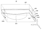
As shown in FIG. 1, the radiographic
放射線画像撮影装置10は、前面(被験者W)側に設けられた側面視で略C字状の形状を有する撮影部12と、撮影部12よりもY方向(背面)側に配設され撮影部12を背面側から支える基台部14とを備えている。撮影部12は、下方側から上方側に向かって、撮影台22と、保持部28と、圧迫板26と、支持部29とを備えている。撮影台22には被験者Wの乳房Nに当接される撮影面20を備えている。特に形状が限定されるものではないが、ここでは平面視において撮影面20の形状は方形状とされている。放射線透過性や機械的強度の観点から、少なくとも撮影面20は例えば炭素繊維強化プラスチックにより形成されている。保持部28の下方側には撮影台22が支持されており、保持部28の撮影台22によりも上方側には圧迫板26が支持されている。
The radiographic
圧迫板26は、撮影面20との間に乳房Nを挟込み、この乳房Nを圧迫する構成とされている。圧迫板26の形状は平面視において方形状とされており、この圧迫板26はZ方向に厚みを持つ立方体形状により構成されている。圧迫板26は、撮影面20に対して垂直方向(図1ではZ方向)に移動可能とされており、撮影面20に対して平行状態において乳房Nを圧迫する構成とされている。また、圧迫板26は、それと保持部28との間に設けられた回転支点45を中心として回転可能とされており、撮影面20に対して角度を持って乳房Nを圧迫可能な(圧迫傾斜可能な)構成とされている。つまり、圧迫板26は回転支点45を中心として乳房Nの根元側に拡がりを持って傾斜されるので、乳房Nが圧迫されたときの被験者Wの痛みを軽減することができる。図示が省略されているが、回転支点45又はその近傍には、圧迫傾斜角度を検出する角度検出センサが設けられている。なお、圧迫板26の詳細な構造並びに動作は後に詳細に説明する。
The
支持部29は、保持部28の上方にそれとは別部品として設けられており、側面視において略逆L字状の形状により構成されている。この支持部29の上側には撮影面20に向けて撮影用或いは測定用として放射線が照射可能とされる放射線照射部24が設けられている。
The
図1に示されるように、基台部14の上方側には前面側に向かって水平方向に突出された回動軸16が設けられており、この回動軸16には支持部29及び保持部28が取付けられている。つまり、回転軸16を回転中心として、基台部14に対して、支持部29を含む撮影部12が回転可能とされている。
As shown in FIG. 1, a rotating
また、回転軸16と保持部28との連結及び非連結の切替えが可能とされている。この切替えを実現するため、例えば、噛合い状態と非噛合い状態とを切替えられる歯車が回転軸16及び保持部28に設けられている。連結状態にあるとき、回転軸16の回転と共に保持部28が回転し、非連結状態にあるとき、回転軸16の回転に対して保持部28が空転する。回転軸16の回転力は、図示を省略しているが、基台部14の内部に設けられた駆動源から伝達されている。
Further, the connection between the
(放射線照射部の構成)
図2に示されるように、放射線照射部24は、放射線源30と、フィルタ24Aとを備えている。放射線源30は、筐体30Aと、その内部に設けられたフィラメントを含む陰極30Bと、ターゲットとして使用される陽極30Cとを備えている。陰極30Bから熱電子が放出されると、陰極30Bと陽極30Cとの間の電位差により熱電子が加速されかつ集束されて陽極30Cに衝突される。これにより、制動放射線が発生する。ここでは、放射線照射部24から制動X線が発生されている。図示が省略されているが、第1実施の形態に係る放射線画像撮影装置10では、放射線源30が複数個配設されており、この複数個の放射線源30のそれぞれの陽極30Cとして採用されている金属の種類が異なっている。陽極30Cには、例えば、タングステン、モリブデン、ロジウム等の金属が採用されている。金属の種類が異なることによって、陽極30Cから発生される制動放射線の強度が異なる。
(Configuration of radiation irradiation unit)
As shown in FIG. 2, the
放射線源30から発生された制動放射線(以下、単に「放射線」と言う場合がある。)は、筐体30Aの下方壁(ここでは底部)に設けられた窓30Dを通して、更に窓30Dの外側に設けられたフィルタ24Aを通して、撮影面20に向けて照射されている。フィルタ24Aは、例えば、モリブデン、ロジウム、アルミニウム、銀のそれぞれの膜を膜面方向に順次繋合わせて構成されている。第1実施の形態に係る放射線画像撮影装置10では、図示を省略した例えばガイドレールに沿ってフィルタ24Aが移動可能とされており、フィルタ24Aのいずれかの金属が窓30Dに対向する構成とされている。すなわち、窓30Dから照射される放射線がフィルタ24Aの種類を変えた金属を通して撮影面20に向けて照射可能であるため、放射線の特性が適宜変更可能とされている。
The bremsstrahlung generated from the radiation source 30 (hereinafter sometimes simply referred to as “radiation”) passes through a
(放射線検出器の構成)
図1に示されるように、撮影台22の内部には放射線検出器42が設けられている。放射線検出器42では、放射線照射部24から圧迫板26、乳房N及び撮影面20を透過し、乳房Nの画像情報を担持する放射線の照射を受けて画像情報が検出されている。この画像情報は、記憶部47(図4参照)に出力され、記憶部47では乳房Nの放射線画像情報として記憶されている。放射線検出器42には、例えば、放射線をデジタル信号に変換して出力するFPD(Flat Panel Detector)が使用されている。
(Configuration of radiation detector)
As shown in FIG. 1, a
第1実施の形態に係る放射線検出器42には、ここでは図示を省略したシンチレータを用いて放射線が一旦光に変換され、この変換された光が電荷に変換される間接変換方式が採用されている。なお、間接変換方式に限らず、放射線検出器42には、半導体層内で放射線が直接電荷に変換され、この電荷を蓄積する直接変換方式が採用されてもよい。
The
図3に示されるように、放射線検出器42は検出素子(画素)70が複数個配列された検出部60を備えている。検出素子70は、放射線から変換された光を受けて電荷を発生しこの電荷が蓄積される光電変換部74と、光電変換部74に蓄積された電荷が読出されるスイッチング素子72との直列回路により構成されている。光電変換部74には例えばフォトダイオードが使用されている。スイッチング素子72には薄膜トランジスタ(TFT)が使用されている。
As shown in FIG. 3, the
検出素子70は、走査信号線78が延在される方向(例えば行方向)、走査信号線78に対して交差する出力信号線76が延在される方向(例えば列方向)のそれぞれに沿ってマトリックス状に複数配列されている。走査信号線78及び出力信号線76は図示が省略された基板上に設けられている。1個の検出素子70は、1本の走査信号線78と1本の出力信号線76との交差部に配置されており、1本の走査信号線78、1本の出力信号線76のそれぞれに電気的に接続されている。図3に示されている検出部60では、紙面の都合上、検出素子70の配列個数が簡略化されているが、例えば走査信号線78の延在方向に1024個、出力信号線76の延在方向に1024個の検出素子70が配列されている。
The
また、検出部60には、複数本の出力信号線76のそれぞれに対して並列に共通電極線79が延在されている。共通電極線79には一定の電源が供給されており、この共通電極線79は光電変換部74に接続されている。
Further, a
走査信号線78には走査信号制御回路62が接続されており、走査信号制御回路62から走査信号線78に走査信号が供給可能とされている。走査信号の供給、非供給によって走査信号線78に接続された検出素子70のスイッチング素子72の導通、非導通が制御されている。検出素子70では、スイッチング素子72が導通状態に制御されているとき、光電変換部74に蓄積された電荷量に応じてスイッチング素子72に電流が流れる。電荷量並びにそれに応じて流れる電流量は乳房Nの放射線画像情報である。
A scanning
出力信号線76には信号検出回路64が接続されている。検出素子70のスイッチング素子72に流れた電流は検出素子70の出力電気信号として出力信号線76を通して信号検出回路64に出力される。信号検出回路64では、図示が省略されているが、出力信号線76毎に出力電気信号を増幅する増幅回路及びアナログ信号をデジタル信号に変換するAD変換器が内蔵されている。つまり、信号検出回路64において、出力信号線76から入力された出力電気信号(アナログ信号)は増幅回路によって増幅され、そしてAD変換器によってデジタル信号へ変換される。
A
放射線検出器42には検出器制御部66が設けられており、この検出器制御部66は走査信号制御回路62、信号検出回路64のそれぞれに接続されている。検出器制御部66では、信号検出回路64から出力されたデジタル信号のノイズ除去等の所定処理が行われると共に、出力電気信号の検出を制御する制御信号が信号検出回路64へ出力される。また、検出器制御部66では、走査信号の出力を制御する制御信号が走査信号制御回路62へ出力される。この検出器制御部66には、CPU(中央演算処理ユニット:Central Processing Unit)と、ROM(Read Only Memory)、RAM(Random Access Memory)、フラッシュメモリ等の不揮発性記憶部とを備えている。検出器制御部66では、信号検出回路64から出力された検出素子70の出力電気信号に基づいて乳房Nの放射線画像としての画像情報が生成され、この画像情報は放射線画像撮影装置10の記憶部47(図4参照)出力される。
The
なお、図3に示された放射線検出器42では、1個の検出部60に対して1個の走査信号制御回路62及び1個の信号検出回路64が設けられている。走査信号制御回路62及び信号検出回路64は、このような形式に限定されるものではなく、1個の検出部60に対して2個以上の走査信号制御回路62及び2個以上の信号検出回路64が設けられていてもよい。
In the
(放射線画像撮影装置のシステム構成)
図4に示されるように、第1実施の形態に係る放射線画像撮影装置10は、撮影装置制御部48、放射線照射部24、放射線検出器42、操作パネル46、記憶部47、通信部(I/F部)49及び駆動源264を備えている。
(System configuration of radiographic imaging device)
As shown in FIG. 4, the
撮影装置制御部48はCPU51と、ROM52と、RAM54と、HDD(Hard Disk Drive)56とを備えている。これらCPU51等は、コントロールバス、データバス等の共通バス57を介在して互いに接続されており、相互に信号等の送受信が可能とされている。
The photographing
CPU51は放射線画像撮影装置10の全体の制御等を司っている。例えば、ROM52に格納されているプログラム53がCPU51に読込まれると、CPU51はプログラム53を実行して各部の制御を行う。なお、ここでは、予めROM52にプログラム53が格納されている構成とされているが、これに限定はされない。例えば、プログラム53が記録されたCDROM、リムーバブルディスク等の外部記録媒体を作成して、この外部記録媒体からROM52等にプログラム53が格納されてもよい。また、外部装置からインターネット等の通信回線を通してROM52等にプログラム53が格納されてもよい。RAM54はCPU51においてプログラム53を実行するときの作業用領域として使用されており、RAM54にはプログラム53が一時的に格納される。HDD56には放射線画像情報等の各種情報が記憶される。撮影装置制御部48は、その内部に設けられた共通バス57及びその外部に設けられた共通バス58を介在して、放射線照射部24、放射線検出器42、操作パネル46、記憶部47、通信部(I/F部)49、駆動源264のそれぞれに相互に接続されている。
The
放射線画像撮影装置10では、操作者(オペレータ)によって操作パネル46の曝射スイッチが操作されると、放射線の照射指示が発せられる。この照射指示に従って、撮影装置制御部48では、指定された曝射条件に基づいて設定された撮影メニュー(プログラム53)が実行され、放射線照射部24から撮影面20に向かって放射線を照射する制御が行われる。
In the radiographic
操作パネル46は、曝射条件や姿勢情報等の各種操作情報の入力、各種操作指示の設定等を放射線画像撮影装置10と操作者との間において行えるインターフェイスである。曝射条件には管電圧、管電流、照射時間、姿勢情報等の情報が少なくとも含まれている。姿勢情報には、乳房Nに対して複数の方向から撮影を行う場合の撮影姿勢の情報、撮影角度情報等の撮影位置情報が少なくとも含まれている。なお、各種操作情報、各種操作指示情報は放射線を用いた診療、診断等の情報の管理を行うシステム、所謂放射線情報システム(RIS:Radiology Information System)等の外部装置やシステムから取得してもよい。また、各種操作情報、各種操作指示情報は撮影装置制御部48のHDD56に予め格納させてもよい。
The
撮影装置制御部48では、操作パネル46から各種操作情報の入力、各種操作指示の設定がなされると、その設定に基づく撮影メニューが実行されて、放射線照射部24から放射線が被験者Wの乳房Nに照射され、放射線画像が撮影される。上方から乳房Nの放射線画像が撮影される場合、撮影面20が上方を向いた状態に保持部28の姿勢が調整されると共に、放射線照射部24が撮影面20に対して対向する上方に位置する状態に支持部29の姿勢が調整される。これらの調整は撮影装置制御部48により行われる。また、側方から乳房Nの放射線画像が撮影される場合、撮影面20が側方を向いた状態に保持部28の姿勢が調整されると共に、放射線照射部24が撮影面20に対して対向する側方に位置する状態に支持部29の姿勢が調整される。
In the imaging
通信部49は、放射線画像撮影装置10の例えば記憶部47に格納された放射線画像情報を外部装置(例えば外部モニタ)に送信し、又外部装置(例えばRIS)から各種操作情報、各種操作指示等の情報を受信するインターフェイスとして使用されている。通信部49では、有線による情報の送受信に限らず、無線による情報の送受信が行える。
The
(圧迫板の構成)
図5及び図6に示されるように、第1実施の形態に係る放射線画像撮影装置10に組込まれた中空の立方体形状を有する圧迫板26は、圧迫部26Aと、支持部26Bと、反力部26Cとを少なくとも備えている。圧迫部26Aは、撮影台22の撮影面20に対向して配置されており、Z方向の厚さを支持部26Bの厚さに比べて薄くかつ弾性変形可能な構成とされている。圧迫部26Aは、被験者Wの胸壁側に位置されており、平面視においてX方向を長手方向とする矩形形状により構成されている。支持部26Bは、圧迫部26Aと同様に撮影面20に対向して配置されており、圧迫部26Aの背面側の一端に一体に設けられている。つまり、圧迫部26Aと支持部26Bとは同一部材により形成されており、この部材の前面側である一部の厚みを薄くすることによって圧迫部26Aが形成されると共に、残りの一部が支持部26Bとして形成されている。支持部26Bは平面視において矩形形状により構成されており、圧迫部26A及び支持部26Bは側面視で見たときに略L字形状により構成されている。支持部26Bは厚く形成されているので、支持部26Bの全体の剛性が高くされている。逆に、圧迫部26Aは薄く形成されているので、圧迫部26Aの全体の剛性は低くされており、これにより圧迫部26Aが変形可能とされている。
(Composition of compression plate)
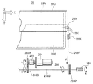
As shown in FIGS. 5 and 6, the
放射線ここでは制動X線が透過し易い性質を有する樹脂材料を用いて圧迫部26Aの圧迫部26A及び支持部26Bが形成されている。具体的な樹脂材料としては、PC(ポリカーボネート)、PET(ポリエチレンテレフタレート)、アクリル、PP(ポリプロピレン)等を実用的に使用することができる。
Radiation Here, the
図5、図6及び図7(A)に示されるように、反力部26Cの前面側である一端部は圧迫部26Aに対して撮影面20とは反対側(図5及び図6中、Z方向)において支持可能とされている。反力部26Cの背面側である他端部は、一端部から下方向に屈曲され、反力調整機構268に連結されている。側面視において反力部26Cは略L字形状により構成されている。反力部26Cの中間部は回転軸26Dを介して支持部26Bに取付けられており、回転軸26Dを回転中心として反力部26Cが回転可能とされている。反力部26Cは、支持力を付勢するために、基本的には圧迫部26Aの弾性率よりも大きい弾性率を有する材料により構成されている。例えば、反力部26Cは金属により製作されている。反力部26Cでは反力調整機構268により圧迫部26Aに付勢する支持力が変更可能とされており、圧迫部26Aが受ける反力に変化が生じる。
As shown in FIGS. 5, 6, and 7 </ b> A, one end, which is the front side of the
図7(A)に示されるように、反力部26Cによる圧迫部26Aの支持力が無い場合には、乳房Nを挟込んだときに生じる反力F1に対して、圧迫部26Aはその弾性率に応じた弾性変形を生じる。この場合は、圧迫板の剛性は低い。これに対して、図7(B)に示されるように、反力部26Cから圧迫部26Aに支持力F2が付勢される(又は大きい)場合には、支持力F2に応じて乳房Nを挟込んだときに生じる反力F1が反力F3に減少される。この場合は、圧迫板の剛性は高い。この反力の変更は圧迫部26Aの形状(断面形状)を変化させることができるので、圧迫部26Aの変形量が調整可能になる。引いては、圧迫板の剛性を変える事ができる。
As shown in FIG. 7A, when there is no support force of the
また、図5、図6、図7(A)及び図7(B)に示されるように、圧迫部26Aの前面側の一部は撮影面20側に突出された局面形状により構成されている。具体的には、この圧迫部26Aの一部は、平面視において、前面側に拡がりを持ち、背面側に向かって徐々に狭まり、乳房Nの形状に類似された円弧形状を有する共に、前面側から背面側に向かって順次突出量が減少されている。これにより、撮影面20と圧迫部26Aとの間に圧迫部26Aよりも柔らかくかつ圧迫部26A側に突出された局面形状を有する乳房(被撮影体)Nが挟まれた場合、圧迫部26Aの局面形状により乳房Nの中央部が押圧されると共にその周囲が押し広げられる。このため、撮影面20と圧迫部26Aとの間に挟まれた乳房Nの厚さを均一化することができる。第1実施の形態では、実用的な圧迫力である40N〜120Nの範囲内において乳房Nの厚さが均一となる局面形状により圧迫部26Aが構成されている。
Further, as shown in FIGS. 5, 6, 7A, and 7B, a part of the front side of the
(圧迫板の反力調整機構の構成)
図5、図6、図7(A)、図7(B)及び図8に示されるように、第1実施の形態に係る圧迫板26の反力調整機構268は、反力部26Cに一端が接続されると共に反力部26Cに支持力を付勢する弾性体268Eと、弾性体268Eの他端に接続されると共にこの弾性体268Eの伸縮を調整する調整部(ここでは符号を省略する)とを備えている。弾性体268Eには例えばコイルばねが使用されている。弾性体268Eの一端は連結ピン26Eを介して支持部26Bに取付けられている。
(Configuration of reaction force adjustment mechanism for compression plate)
As shown in FIGS. 5, 6, 7A, 7B, and 8, the reaction
調整部は、弾性体268Eの他端に接続された連結体268Fと、この連結体268Fの巻取り巻戻しを行うリール268Dと、このリール268Dの巻取り巻戻しの駆動力を発生させる駆動源264と、駆動源264とリール268Dとを連結し駆動源264からの駆動力をリール268Dに伝達する伝達部とを備えている。連結体268Fには例えばワイヤが使用されている。伝達部は、歯車268A、歯車268B及び回転伝達軸268Cにより構成されている。
Adjustment unit includes a resilient member connecting member connected to the other end of
駆動源264には例えば電動モータが使用されている。ここでは、電動モータの回転軸(駆動軸)方向はX方向に一致させている。駆動源264は、支持部26Bの背面に取付けられた板状のブラケット268Hと、ブラケット268Hの中央部に取付けられ平面視において外側に開放されたU字形状のブラケット268Iとを介して支持部26Bに取付けられている。
For example, an electric motor is used as the
伝達部の歯車268Aは、ブラケット268Iに回転自在に取付けられており、駆動源264からの駆動力を受けて回転する。ここでは、駆動源264と歯車268Aとの間にクラッチ266が設けられており、クラッチ266は駆動源264からの駆動力を歯車268Aに伝達する状態と伝達しない状態とに切替え可能とされている。歯車268Bは、同様にブラケット268Iに回転自在に取付けられており、歯車268Aから伝達された駆動力を受けて回転する。回転伝達軸268Cは、歯車268Bの回転軸に繋がれると共にブラケット268Kに回転自在に取付けられており、歯車268Bから伝達された駆動力を受けて回転する。回転伝達軸268Cは圧迫板26の背面において両側面に渡ってX方向に延設されており、回転伝達軸268Cの中央部が歯車268Bに繋がれている。回転伝達軸268Cの両端にはリール268Dが繋がれており、リール268Dは回転伝達軸268Cから伝達される駆動力を受けて回転する。図8に示されるように、例えば駆動源264から歯車268Aに矢印a方向の駆動力(回転)が伝達されると、歯車268Bには矢印a方向とは逆の矢印b方向の駆動力が伝達される。この駆動力は回転伝達軸268Cを介在させてリール268Dに同一の矢印c方向の駆動力として伝達される。
The
リール268Dが回転し、リール268Dに連結体268Fが矢印c方向に巻取られると、図7(B)に示されるように、弾性体268Eに伸びが生じ、反力部26Cによる圧迫部26Aの支持力F2が増加する。この支持力は弾性体268Eの伸びの増加に応じて増加する。一方、リール268Dが逆に回転しリール268Dから連結体268Fが巻戻されると、図7(A)に示されるように、弾性体268Eに縮みが生じ、反力部26Cによる圧迫部26Aの支持力F2が減少する。
When the
また、図6及び図8に示されるように、第1実施の形態に係る圧迫板26では、反力調整機構268の調整部具体的には回転伝達軸268Cの両端にそれぞれ連結されており、駆動源264からの駆動力とは別にリール268Dにそれを移動可能とする駆動力を与える手動調整部269が設けられている。図8において、操作者によって矢印g方向の駆動力が手動調整部269に与えられると、この駆動力に従ってリール268Dが回転する。なお、手動調整部269から駆動力が与えられるときには、駆動源264と歯車268Aとの連結状態がクラッチ266により解除される。駆動源264は手動調整部269から駆動力を与えるときの負荷になるので、連結状態が解除されることにより、手動調整部269を用いたリール268Dの操作が容易に行える。
Further, as shown in FIGS. 6 and 8, in the
(放射線画像撮影装置及び圧迫板の動作)
第1実施の形態に係る放射線画像撮影装置10及び圧迫板26の動作は以下の通りである。図9に示されるように、まず最初に、被験者Wの受診履歴が有るか否かが判断される(S10)。ここで、受診履歴が有るとは、過去に乳房Nの放射線画像の撮影を実施しており、この撮影のときの圧迫板26の圧迫部26Aの変形量を決定するための情報が既に有るという意味である。従って、受診履歴が無いとは、そのような情報が無いという意味である。受診履歴が有るか否かの判断は放射線画像撮影装置10によって実施されている。すなわち、受診履歴が有るか否かの判断に必要な情報が図4に示される操作パネル46から入力されると、撮影装置制御部48は記憶部47に記憶された過去の受診履歴を検索する。ここで、判断に必要な情報とは、例えば被験者Wの氏名、健康保健書の番号及び診察券の番号の情報のうち少なくともいずれか1つの情報である。検索の結果、記憶部47に該当する情報が記憶されている場合には撮影装置制御部48は受診履歴が有ると判断する。また、記憶部47に該当する情報が記憶されていない場合には撮影装置制御部48は受診履歴が無いと判断する。なお、受診履歴が有るか否かの判断は被験者Wに対する医師の問診によっても実施可能である。この場合には、判断結果に基づいて、医師又は放射線画像撮影装置10の操作者が操作パネル46から判断結果を入力する。
(Operation of radiographic imaging device and compression plate)
Operations of the radiographic
被験者Wの受診履歴が無い場合には、放射線画像撮影装置10において、被験者Wの乳房Nのプレ圧迫が実施される(S12)。プレ圧迫は、放射線撮影のときのポジショニング圧迫に対して事前に実施される圧迫である。具体的には、プレ圧迫では、撮影台22の撮影面20と圧迫板26の圧迫部26Aとの間に乳房Nが挟込まれ、被験者Wが痛みを感じない程度の軽い圧迫力、例えば60N〜80N程度の圧迫力によって乳房Nが圧迫される。
When there is no medical examination history of the subject W, pre-compression of the breast N of the subject W is performed in the radiographic imaging device 10 (S12). The pre-compression is a pre-compression performed for the positioning compression at the time of radiography. Specifically, in the pre-compression, the breast N is sandwiched between the
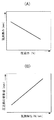
図10(A)には圧迫力と乳房Nの厚みとの関係の一例が示されている。図10(A)において、横軸は圧迫力(N)であり、縦軸は乳房Nの厚み(mm)である。同図に示されるように、一般的に圧迫力の増加に伴い乳房Nの厚みは薄くなる傾向にあるが、この傾向には被験者Wの乳房Nの例えば乳腺密度等の違いにより多少の違いがある。プレ圧迫において、圧迫力が加わったときの乳房Nの厚みが測定されると、圧迫力と厚みとの関係から乳房弾性(N/mm)が導出される(S14)。この乳房弾性は圧迫力を厚みで割った値である。乳房弾性の導出には、圧迫力の値と乳房Nの厚みの値との関係から乳房弾性の値が導き出させるテーブルが使用されている。このテーブルは前述の図4に示される放射線画像撮影装置10の記憶部47に予め記憶されている。乳房弾性の値には、極めて高い精度の値が要求されないので、幅を持たせたデジタル値として取扱うことが有利である。すなわち、テーブルによって乳房弾性が導出される結果として、この導出のためのシステムサイズ(例えば、演算能力)の小型化が可能となる。また、乳房弾性は、図4に示される撮影装置制御部48において、演算式を含むプログラム53を予めROM52に格納し、乳房Nの圧迫力の値と厚みの値とを操作パネル46から入力することにより、CPU51を用いた演算によって導出してもよい。更に、図4に示される放射線画像撮影装置10において、乳房弾性を導出するための専用回路が構築されてもよい。なお、乳房弾性の値は、乳房Nの圧迫力、厚さのいずれか一方の値を固定し、いずれか他方の値によって例えばテーブルから導出してもよい。
FIG. 10A shows an example of the relationship between the compression force and the thickness of the breast N. In FIG. 10A, the horizontal axis is the compression force (N), and the vertical axis is the thickness (mm) of the breast N. As shown in the figure, generally, the thickness of the breast N tends to become thinner as the compression force increases, but this tendency is somewhat different due to, for example, the density of the breast N of the subject W. is there. In the pre-compression, when the thickness of the breast N when the compression force is applied is measured, the breast elasticity (N / mm) is derived from the relationship between the compression force and the thickness (S14). The breast elasticity is a value obtained by dividing the compression force by the thickness. For deriving the breast elasticity, a table is used in which the breast elasticity value is derived from the relationship between the compression force value and the breast N thickness value. This table is stored in advance in the
乳房弾性が導出されると、図10(B)に示されるように、被験者Wが痛みを感じ難い圧迫板26の変形量が導出される(S16)。図10(B)において、横軸は乳房弾性(N/mm)であり、縦軸は圧迫部26Aの変形量(mm)である。被験者Wの乳房Nが硬い場合、乳房弾性の値は高く、一般的に被験者Wは比較的痛みを感じ易い。このため、圧迫部26Aの前面側(胸壁側)の変形量が大きくなる値が導出されている。一方、被験者Wの乳房Nが柔らかい場合、乳房弾性の値が低く、一般的に被験者Wは比較的痛みを感じ難い。このため、圧迫部26Aの前面側の変形量が小さくなる値が導出されている。乳房弾性の導出と同様の理由から、圧迫部26Aの変形量の導出には、乳房弾性の値から圧迫部26Aの変化量が導き出させるテーブルが使用されている。このテーブルは前述の図4に示される放射線画像撮影装置10の記憶部47に予め記憶されている。また、圧迫部26Aの変形量の導出は、演算による導出或いは専用回路による導出であってもよい。
When the breast elasticity is derived, as shown in FIG. 10B, the deformation amount of the
次に、導出された圧迫部26Aの変形量に基づき、圧迫板26の反力部26Cによる圧迫部26Aの支持力の調整が行われる(S18)。この支持力の調整では、前述の図4に示される放射線画像撮影装置10の記憶部47に格納されたテーブルから圧迫部26Aの変形量の情報が撮影装置制御部48に読込まれる。撮影装置制御部48では、この変化量の情報に従い駆動源264の駆動力の制御が行われる。駆動源264の駆動力は図5、図6及び図8に示される反力調整機構268に伝達される。反力調整機構268では、駆動源264の駆動力が歯車268A、歯車268B、回転伝達軸268C、リール268Dのそれぞれに伝達される。リール268Dによって連結体268Fの巻取り又は巻戻しが行われると、弾性体268Eには伸び又は縮みが生じ、反力部26Cの圧迫部26Aへの支持力F2が調整される。この支持力F2の調整は、例えば、駆動源264の駆動量の調整、例えば電動モータの場合はその回転数の調整により行う。
Next, based on the derived deformation amount of the
圧迫部26Aの変形量の調整を自動により実施しない場合、又は微調整を手動により行う場合には、手動調整部269が操作者により操作される。手動調整部269が操作されるときには、クラッチ266により、駆動源264と伝達部の歯車268Aとの連結が解除される。
When the adjustment of the deformation amount of the
ここで、ステップS10において、被験者Wの受診履歴が有る場合には、過去に圧迫板26の圧迫部26Aの変形量を決定するための情報が図4に示される記憶部47に記憶されているので、この情報が記憶部47から撮影装置制御部48に入力される(S24)。この情報の入力に基づき、ステップS18において、同様に圧迫部26Aの支持力の調整が行われる。なお、変形量を決定するための情報は、医師又は操作者によって操作パネル46からも入力可能とされている。
Here, in step S10, when there is a medical history of the subject W, information for determining the deformation amount of the
次に、反力部26Cの支持力F2の調整が行われ、圧迫部26Aの変形量が調整された圧迫板26によって、被験者Wの乳房Nのポジショニング圧迫が実施される(S20)。ポジショニング圧迫は、実際に放射線撮影のときに実施される圧迫であり、例えば80N〜120N程度の圧迫力によって乳房Nが圧迫される。ポジショニング圧迫では、圧迫部26Aの一部が撮影面20側に突出する局面形状により形成されているので、全体的に平坦になるように乳房Nを圧迫することができる。ここで、圧迫板26の圧迫部26Aの変形量が乳房Nの硬さに応じて最適に調整されている。このため、乳房Nが圧迫されても、被験者Wは痛みを感じ難い。
Next, the support force F2 of the
ポジショニング圧迫がなされた状態において、図1に示される放射線照射部24から乳房Nに向けて制動放射線が照射され、撮影台22の放射線検出器42を介在して乳房Nの放射線画像が撮影される(S22)。この後、圧迫板26による乳房Nの圧迫が解除されると共に、撮影が終了する。
In a state in which the positioning pressure is applied, the bremsstrahlung is irradiated from the
(第1実施の形態の作用及び効果)
第1実施の形態に係る圧迫板26では、弾性変形が可能な圧迫部26Aを支持可能な反力部26Cが設けられており、この反力部26Cによる圧迫部26Aの支持力が変更可能とされている。圧迫部26Aへの支持力の変更に応じて、圧迫部26Aの反力に変化が生じる。この圧迫部26Aの反力を変えることで、圧迫部26Aの変形量を調整することができる。従って、同一の圧迫圧力状態における圧迫部26Aの変形量の最適化を図ることができる。例えば、放射線画像撮影装置10としてのマンモグラフィに取付けられた圧迫板26では、被験者Wの乳房Nが撮影台22の撮影面20と圧迫部26Aとの間に同一の圧迫圧力状態において挟込まれた場合であっても、乳房Nの状態に応じて圧迫部26Aの変形量を調整することができる。痛みを感じる被験者Wに対して圧迫部26Aの変形量を大きくすることにより、被験者Wの痛みを軽減することができる。
(Operation and effect of the first embodiment)
In the
また、第1実施の形態に係る圧迫板26では、反力調整機構268が設けられているので、反力部26Cの支持力を変更することができる。
Further, in the
また、第1実施の形態に係る圧迫板26では、圧迫部26Aと支持部26Bとが同一部材により形成されており、支持部26Bの厚さに比べて薄くすることで圧迫部26Aを形成することができる。このため、簡易な構造により、圧迫板26の製作が可能とされる。
Further, in the
また、第1実施の形態に係る圧迫板26では、反力部26Cが、一端部で圧迫部26Aを支持可能とされ、他端部で反力調整機構268に連結され、中間部で支持部26Bに回転可能とされた簡易な構成とされている。このため、簡易な構造により、圧迫部26Aの製作が可能とされる。
Further, in the
また、第1実施の形態に係る圧迫板26では、撮影面20と圧迫部26Aとの間に圧迫部26Aよりも柔らかくかつ圧迫部26A側に突出した局面形状を有する乳房N(被撮影体)が挟まれる場合、圧迫部26Aの局面形状により乳房Nの中央部が押圧されると共にその周囲が押し広げられる。このため、撮影面20と圧迫部26Aとの間に挟まれた乳房Nの厚さを均一化することができる。
In the
また、第1実施の形態に係る圧迫板26では、反力調整機構268が弾性体268Eとこの弾性体268Eの伸縮を調整する調整部とを備えた構成とされている。このため、反力調整機構268の構造が簡素化されているので、簡易な構造により圧迫板26を製作することができる。
In the
また、第1実施の形態に係る圧迫板26では、調整部が連結体268F、リール268D、駆動源264及び伝達部を備えているので、駆動源264からの駆動力によって反力部26Cの支持力を調整することができる。従って、反力部26Cの支持力の調整並びに圧迫部26Aの変形量の調整を自動化することができる。
Further, in the
また、第1実施の形態に係る圧迫板26では、調整部に連結された手動調整部269が設けられているので、この手動調整部269を用いて駆動源264からの駆動力とは別に手動において反力部26Cの支持力並びに圧迫部26Aの変形量を調整することができる。
Further, in the
また、第1実施の形態に係る放射線画像撮影装置10では、圧迫板26、撮影台22、放射線照射部24及び撮影装置制御部48が備えられており、撮影装置制御部48は、駆動源264の駆動力を制御し、反力調整機構268を介在して反力部26Cの支持力を調整する構成とされている。従って、撮影装置制御部48により反力部26Cの支持力並びに圧迫部26Aの変形量の調整を自動で行うことができる。
In addition, the radiographic
また、第1実施の形態に係る放射線画像撮影装置10では、圧迫厚み、圧迫力の少なくともいずれか1つの情報に基づいて、撮影装置制御部48による反力部26Cの支持力並びに圧迫部26Aの変形量が調整されている。このため、被験者Wに応じて、圧迫部26Aの変形量を自動で調整することができる。
Moreover, in the
[第2実施の形態]
本発明の第2実施の形態は、第1実施の形態に係る放射線画像撮影装置10において圧迫板26の圧迫部26Aの変形量の調整を被撮影体の人体組織の密度に基づいて実施した例を説明するものである。
[Second Embodiment]
The second embodiment of the present invention is an example in which the amount of deformation of the
(放射線画像撮影装置及び圧迫板の動作)
第2実施の形態に係る放射線画像撮影装置10及び圧迫板26の動作は以下の通りである。図11に示されるように、第1実施の形態に係る放射線画像撮影装置10及び圧迫板26の動作と同様に、ステップS10の受診履歴の判断の結果、受診履歴が無い場合にはステップS12のプレ圧迫が実施される。
(Operation of radiographic imaging device and compression plate)
The operations of the radiographic
プレ圧迫に引き続き、プレ放射線撮影が実施される(S26)。プレ放射線撮影は、被験者Wの乳房Nの人体組織の密度、ここでは乳腺密度を最低限測定可能な放射線撮影である。従って、プレ放射線撮影のときの放射線量はステップS22の放射線撮影のときの放射線量に比べて低く設定されている。例えば、放射線量は、プレ放射線撮影のときに0.2mGy、放射線撮影のときに2mGyに設定されている。 Subsequent to the pre-compression, pre-radiography is performed (S26). The pre-radiography is radiography capable of measuring the density of the human tissue of the breast N of the subject W, in this case, the density of the mammary gland at a minimum. Therefore, the radiation dose at the time of pre-radiography is set lower than the radiation dose at the time of radiography in step S22. For example, the radiation dose is set to 0.2 mGy during pre-radiography and 2 mGy during radiography.
このプレ放射線撮影により得られた撮影画像に基づき、乳房Nの乳腺密度を導出することができる(S28)。図12(A)には、被験者Wの側面側からX線を照射して撮影された乳房Nの画像を模式的に示した(1)〜(6)までの6つのサンプルが示されている。乳房N内の部位は乳腺である。左側の(1)に示すサンプルから右側の(6)に示すサンプルに向かって、単位面積(ここでは単位断面積)当たりの乳腺の割合いが多くなっている。X線撮影の画像において、乳房Nの断面積と乳腺の面積との比率から乳腺密度を算出することができる。例えば、(1)に示すサンプルから(6)に示すサンプルに向かって乳腺密度(%)が増加傾向にある。ここで、最も左の(1)に示すサンプルの乳房Nの乳腺密度が基準とされるとき、(2)に示すサンプルの乳腺密度は5%〜10%、(3)に示すサンプルの乳腺密度は15%〜20%、(4)に示すサンプルの乳腺密度は25%〜40%、(5)に示すサンプルの乳腺密度は50%〜70%、(6)に示すサンプルの乳腺密度は75%〜80%である。 Based on the photographed image obtained by the pre-radiography, the breast density of the breast N can be derived (S28). FIG. 12 (A) shows six samples (1) to (6) schematically showing images of the breast N taken by irradiating X-rays from the side of the subject W. . The site in the breast N is the mammary gland. From the sample shown on the left side (1) to the sample shown on the right side (6), the ratio of the mammary gland per unit area (here, the unit cross-sectional area) increases. In an X-ray image, the mammary gland density can be calculated from the ratio between the cross-sectional area of the breast N and the mammary gland area. For example, the mammary gland density (%) tends to increase from the sample shown in (1) to the sample shown in (6). Here, when the breast density of the breast N of the sample shown in the leftmost (1) is used as a reference, the breast density of the sample shown in (2) is 5% to 10%, and the breast density of the sample shown in (3) 15% to 20%, the mammary density of the sample shown in (4) is 25% to 40%, the mammary density of the sample shown in (5) is 50% to 70%, and the mammary density of the sample shown in (6) is 75%. % To 80%.
乳房Nの乳腺密度が導出されると、図12(B)に示されるように、圧迫板26の圧迫部26Aの変形量が導出される(S16)。図12(B)において、横軸は乳腺密度(%)であり、縦軸は前述の図10(B)に示される縦軸と同様に圧迫部26Aの変形量(mm)である。被験者Wの乳房Nの乳腺密度が高い場合、乳房Nは硬く、一般的に被験者Wは比較的痛みを感じ易い。このため、圧迫部26Aの前面側の変形量が大きくなる値が導出されている。一方、被験者Wの乳房Nの乳腺密度が低い場合、乳房Nは柔らかく、一般的に被験者Wは比較的痛みを感じ難い。このため、圧迫部26Aの前面側の変形量が小さくなる値が導出されている。第1実施の形態に係る乳房弾性の導出と同様の理由から、変形量の導出には、乳腺密度の値から変形量が導き出させるテーブルが使用されている。このテーブルは前述の図4に示される放射線画像撮影装置10の記憶部47に予め記憶されている。また、変形量の導出は、演算による導出或いは専用回路による導出であってもよい。
When the mammary gland density of the breast N is derived, as shown in FIG. 12B, the deformation amount of the
次に、導出された変形量に基づき、反力部26Cの支持力の調整が行われる(S18)。この調整方法は第1実施の形態に係る圧迫部26Aの支持力の調整方法と同様である。なお、ステップS10において被験者Wの受診履歴が有る場合には、ステップS24において必要な情報が入力される。そして、ステップS18において、この情報の入力に基づき反力部26Cの支持力の調整が行われる。
Next, the support force of the
次に、反力部26Cの支持力並びに圧迫部26Aの変形量が調整された圧迫板26によって、被験者Wの乳房Nのポジショニング圧迫が実施される(S20)。ポジショニング圧迫では、圧迫板26の圧迫部26Aの変形量が乳房Nの乳腺密度に応じて最適に調整されている。このため、乳房Nが圧迫されても、被験者Wは痛みを感じ難い。
Next, positioning compression of the breast N of the subject W is performed by the
ポジショニング圧迫がなされた状態において、図1に示される放射線照射部24から乳房Nに向けて制動放射線が照射され、撮影台22の放射線検出器42を介在して乳房Nの放射線画像が撮影される(S22)。この後、圧迫板26による乳房Nの圧迫が解除されると共に、撮影が終了する。
In a state in which the positioning pressure is applied, the bremsstrahlung is irradiated from the
(第2実施の形態の作用及び効果)
第2実施の形態に係る圧迫板26及び放射線画像撮影装置10では、前述の第1実施の形態に係る圧迫板26及び放射線画像撮影装置10により得られる作用及び効果と同様の作用及び効果を得ることができる。
(Operation and effect of the second embodiment)
In the
また、第2実施の形態に係る放射線画像撮影装置10では、人体組織の密度、具体的には乳腺密度の情報に基づいて、撮影装置制御部48による反力部26Cの支持力の調整が制御されている。このため、被験者Wの乳房Nに応じて、圧迫板26の圧迫部26Aの変形量を自動で調整することができる。
Further, in the
なお、第2実施の形態では、人体組織の密度として乳腺密度が使用されているが、これに限られるものではない。例えば、人体組織として、皮下脂肪、クーパー靱帯等が使用可能である。また、人体組織の密度の導出に関しては、放射線撮影に限るものではなく、超音波検査が併用可能である。 In the second embodiment, the mammary gland density is used as the density of the human body tissue, but the present invention is not limited to this. For example, subcutaneous fat, Cooper ligament, etc. can be used as human tissue. In addition, the derivation of the density of the human tissue is not limited to radiography, and an ultrasonic examination can be used in combination.
[第3実施の形態]
本発明の第3実施の形態は、第2実施の形態に係る放射線画像撮影装置10において圧迫板26の圧迫部26Aの変形量の調整を被撮影体の放射線透過率に基づいて実施した例を説明するものである。
[Third Embodiment]
The third embodiment of the present invention is an example in which the amount of deformation of the
(放射線画像撮影装置の全体構成)
図13に示されるように、第3実施の形態に係る放射線画像撮影装置10は、撮影台22の内部であって撮影面20と放射線検出器42との間にAEC(Automatic Exposure Control)センサ59が設けられている。このAECセンサ59は、図示が省略されているが、撮影面20を平面視で見たときにマトリックス状に複数個配置されている。例えば、AECセンサ59は、X方向に3個、Y方向に3個の合計9個を配置している。図14に示されるように、AECセンサ59は共通バス58を介在させて撮影装置制御部48等に接続されている。
(Overall configuration of radiographic imaging device)
As shown in FIG. 13, the radiographic
(放射線画像撮影装置及び圧迫板の動作)
前述の第2実施の形態に係る放射線画像撮影装置10の図11に示された制御フローチャートのステップS26において、AECセンサ59は、プレ放射線撮影によって照射され、被験者Wの乳房Nを透過した放射線量を測定する。更に、放射線量を測定したときの乳房Nの厚さが測定される。放射線量の測定結果と乳房Nの厚さとから乳房Nの放射線透過率を導出することができる。この放射線透過率は、撮影装置制御部48において、AECセンサ59から送信された放射線量の測定結果と操作パネル46から入力される乳房Nの厚さとから容易に導出することができる。導出方法には、第1実施の形態に係る放射線画像撮影装置10と同様に、テーブル、演算、専用回路のいずれかの方法が使用可能である。
(Operation of radiographic imaging device and compression plate)
In step S26 of the control flowchart shown in FIG. 11 of the
乳房Nの放射線透過率が導出されると、これに基づいて圧迫板26の変形量を導出することができる。例えば乳腺密度が高いために被験者Wの乳房Nの放射線透過率が低い場合、乳房Nは硬く、一般的に被験者Wは比較的痛みを感じ易い。このため、圧迫部26Aの前面側の変形量が大きくなる値が導出されている。一方、被験者Wの乳房Nの放射線透過率が高い場合、乳房Nは柔らかく、一般的に被験者Wは比較的痛みを感じ難い。このため、圧迫部26Aの前面側の変形量が小さくなる値が導出されている。第1実施の形態に係る乳房弾性の導出と同様の理由から、変形量の導出には、放射線透過率の値と乳房Nの厚さとから変形量が導き出させるテーブルが使用されている。このテーブルは前述の図4に示される放射線画像撮影装置10の記憶部47に予め記憶されている。また、圧迫部26Aの変形量の導出は、演算による導出或いは専用回路による導出であってもよい。
When the radiation transmittance of the breast N is derived, the deformation amount of the
この後、前述の図11に示される制御フローチャートのステップS18以降の処理が実施され、乳房Nの放射線画像が撮影される。 Thereafter, the processing after step S18 of the control flowchart shown in FIG. 11 is performed, and a radiation image of the breast N is captured.
(第3実施の形態の作用及び効果)
第3実施の形態に係る圧迫板26及び放射線画像撮影装置10では、前述の第2実施の形態に係る圧迫板26及び放射線画像撮影装置10により得られる作用及び効果と同様の作用及び効果を得ることができる。
(Operation and effect of the third embodiment)
The
また、第3実施の形態に係る放射線画像撮影装置10では、放射線透過率の情報に基づいて、撮影装置制御部48による反力部26Cによる圧迫部26Aの支持力が制御されている。このため、被験者Wの乳房Nに応じて、圧迫板26の圧迫部26Aの変形量を自動で調整することができる。
Further, in the
[第4実施の形態]
本発明の第4実施の形態は、第1〜第3実施の形態のいずれかに係る圧迫板26の変形例を説明するものである。
[Fourth embodiment]
The fourth embodiment of the present invention describes a modification of the
(圧迫板の構成)
第4実施の形態に係る圧迫板26には、図15に示されるように、反力部26Cの一端部を圧迫部26A側に一定以上回転させないストッパ部26Hが設けられており、圧迫部26Aと反力部26Cの一端部との間に隙間26Gが設けられている。
(Composition of compression plate)
As shown in FIG. 15, the
(第4実施の形態の作用及び効果)
第4実施の形態に係る圧迫板26では、隙間26Gにより、反力部26Cで支持されるまで圧迫部26Aの弾性率に応じて圧迫部26Aの弾性変形が可能となる。圧迫部26Aが反力部26Cにより支持されると反力部26Cの支持力に応じて圧迫部26Aの変形量が小さくなるが、反力部26Cに支持されないまでは圧迫部26Aの変形量が大きい。このため、痛みを感じる被験者Wに対して、圧迫開始の初期段階での圧迫部26Aの変形量を大きくすることにより、被験者Wの痛みを軽減することができる。
[第5実施の形態]
本発明の第5実施の形態は、第4実施の形態に係る圧迫板26の更なる変形例を説明するものである。
(Operation and effect of the fourth embodiment)
In the
[Fifth Embodiment]
The fifth embodiment of the present invention describes a further modification of the
(圧迫板の構成)
第5実施の形態に係る圧迫板26には、図16に示されるように、圧迫部26A及び支持部26Bに比べて弾性率が小さい間隙部材26Iが隙間26Gに設けられている。ここで、間隙部材26Iは、隙間26Gの全域に設けられているが、前面側(胸壁側)の一部に設けられていてもよい。間隙部材26Iには、例えばゴム、スポンジ等の柔軟性部材が使用される。この柔軟性部材は圧迫部26A、反力部26Cの一方に例えば接着剤により接着されている。
(Composition of compression plate)
As shown in FIG. 16, the
(第5実施の形態の作用及び効果)
第5実施の形態に係る圧迫板26では、隙間部材26Iにより、反力部26Cで支持されるまで、間隙部材26Iの弾性率及び圧迫部26Aの弾性率に応じた圧迫部26Aの弾性変形が可能となる。圧迫部26Aが反力部26Cにより支持されると圧迫部26Aの変形量が小さくなるが、反力部26Cに支持されないまでは圧迫部26Aの変形量が大きい。このため、痛みを感じる被験者Wに対して、圧迫開始の初期段階での圧迫部26Aの変形量を大きくすることにより、被験者Wの痛みを軽減することができる。更に、第5実施の形態に係る圧迫板26では、隙間26Gが間隙部材26Iにより塞がれているので、被験者Wが隙間26Gに挟まれることを防止することができる。
(Operation and effect of the fifth embodiment)
In the
(その他の実施の形態)
以上、本発明を複数の実施の形態を用いて説明したが、本発明は、上記実施の形態に限定されるものではなく、本発明の要旨を逸脱しない範囲において種々変更可能である。例えば、本発明は、前述の第1実施の形態〜第5実施の形態の少なくともいずれか2つ以上を組合わせた構造を有する圧迫板26及び放射線画像撮影装置10としてもよい。
(Other embodiments)
The present invention has been described using a plurality of embodiments. However, the present invention is not limited to the above embodiments, and various modifications can be made without departing from the scope of the present invention. For example, the present invention may be the
また、前述の実施の形態に係る放射線ではX線が使用されているが、これに限定されるものではなく、本発明では、少なくとも医療に利用されるγ線、電子線、中性子線、陽子線、重粒子線等の放射線が含まれる。更に、前述の実施の形態に係る放射線画像撮影装置及び圧迫板はマンモグラフィ及びその圧迫板に適用した例を説明したが、これに限定されるものではない。例えば、本発明は、胃腸等の被撮影体のX線撮影を行うために腹部を圧迫する圧迫板及びそれが組込まれたX線画像撮影装置に適用可能である。 Moreover, although X-rays are used in the radiation according to the above-described embodiment, the present invention is not limited to this. In the present invention, at least γ-rays, electron beams, neutron beams, and proton beams used for medical treatment. , Radiation such as heavy particle beams. Furthermore, although the radiographic imaging apparatus and compression board which concern on the above-mentioned embodiment demonstrated the example applied to mammography and its compression board, it is not limited to this. For example, the present invention can be applied to a compression plate that compresses the abdomen in order to perform X-ray imaging of a subject such as the gastrointestinal tract and an X-ray imaging apparatus incorporating the compression plate.
10 放射線画像撮影装置
24 放射線照射部
26 圧迫板
26A 圧迫部
26B 支持部
26C 反力部
26D 回転軸
26E 連結ピン
26G 間隙
26I 間隙部材
264 駆動源
266 クラッチ
268 反力調整機構
268D リール
268E 弾性体
268F 連結体
269 手動調整部
42 放射線検出部
46 操作パネル
47 記憶部
48 撮影装置制御部
59 AECセンサ
DESCRIPTION OF
Claims (10)
前記撮影面とは反対側において前記圧迫部の支持力が変更可能とされ、同一の圧迫圧力状態における前記圧迫部の変形量の大小を調整する反力部と、
を備えた圧迫板。 A compression part capable of elastic deformation disposed opposite to the imaging surface of the imaging table;
The previous SL Taking Kagemen is possible to change the supporting force of the compression unit on the opposite side, and a reaction force unit for adjusting the amount of deformation of the magnitude of the compression unit in the same compression pressure conditions,
Compression plate with
前記反力部の一端部は前記圧迫部を支持可能とすると共に前記反力部の他端部は前記反力調整機構に連結され、かつ前記反力部の中間部が前記支持部に回転可能に設けられている請求項2に記載の圧迫板。 A support portion provided integrally with one end of the compression portion;
One end portion of the reaction force portion can support the compression portion, the other end portion of the reaction force portion is connected to the reaction force adjustment mechanism, and an intermediate portion of the reaction force portion can rotate to the support portion. The compression plate according to claim 2, wherein
前記反力部に一端が接続されると共に前記反力部に支持力を付勢する弾性体と、
前記弾性体の他端に接続されると共にこの弾性体の伸縮を調整する調整部と、
を備えた請求項2〜請求項6のいずれか1項に記載の圧迫板。 The reaction force adjusting mechanism is
An elastic body having one end connected to the reaction force portion and biasing a support force to the reaction force portion;
An adjustment unit that is connected to the other end of the elastic body and adjusts the expansion and contraction of the elastic body;
The compression plate according to any one of claims 2 to 6, further comprising:
前記弾性体の他端に接続された連結体と、
前記連結体の巻取り巻戻しを行うリールと、
前記リールの巻取り巻戻しの駆動力を発生させる駆動源と、
前記駆動源と前記リールとを連結し、前記駆動源からの駆動力を前記リールに伝達する伝達部と、
を備えている請求項7に記載の圧迫板。 The adjustment unit is
A coupling body connected to the other end of the elastic body;
A reel for winding and rewinding the connecting body ;
A driving source for generating a driving force for winding and rewinding the reel;
A transmission unit that couples the driving source and the reel, and transmits a driving force from the driving source to the reel;
The compression plate according to claim 7, comprising:
前記圧迫板の前記圧迫部に対向された撮影面を有する撮影台と、
前記撮影台に対向して前記圧迫板を介して配置された放射線照射部と、
前記駆動源の駆動力を制御し、前記反力調整機構を介して前記反力部の支持力を調整する撮影装置制御部と、
を備えた放射線画像撮影装置。 The compression plate according to claim 8 or 9, and
An imaging table having an imaging surface facing the compression portion of the compression plate;
A radiation irradiating unit arranged via the compression plate facing the imaging table;
An imaging device controller that controls the driving force of the driving source and adjusts the supporting force of the reaction force part via the reaction force adjustment mechanism;
A radiographic imaging apparatus comprising:
Priority Applications (3)
| Application Number | Priority Date | Filing Date | Title |
|---|---|---|---|
| JP2012218265A JP5661712B2 (en) | 2012-09-28 | 2012-09-28 | Compression plate and radiographic imaging device |
| EP13184762.6A EP2716228B1 (en) | 2012-09-28 | 2013-09-17 | Press plate and radiographic imaging apparatus |
| US14/033,899 US9339244B2 (en) | 2012-09-28 | 2013-09-23 | Press plate and radiographic imaging apparatus |
Applications Claiming Priority (1)
| Application Number | Priority Date | Filing Date | Title |
|---|---|---|---|
| JP2012218265A JP5661712B2 (en) | 2012-09-28 | 2012-09-28 | Compression plate and radiographic imaging device |
Publications (3)
| Publication Number | Publication Date |
|---|---|
| JP2014068885A JP2014068885A (en) | 2014-04-21 |
| JP2014068885A5 JP2014068885A5 (en) | 2014-05-29 |
| JP5661712B2 true JP5661712B2 (en) | 2015-01-28 |
Family
ID=49170623
Family Applications (1)
| Application Number | Title | Priority Date | Filing Date |
|---|---|---|---|
| JP2012218265A Active JP5661712B2 (en) | 2012-09-28 | 2012-09-28 | Compression plate and radiographic imaging device |
Country Status (3)
| Country | Link |
|---|---|
| US (1) | US9339244B2 (en) |
| EP (1) | EP2716228B1 (en) |
| JP (1) | JP5661712B2 (en) |
Families Citing this family (20)
| Publication number | Priority date | Publication date | Assignee | Title |
|---|---|---|---|---|
| JP5661711B2 (en) * | 2012-09-28 | 2015-01-28 | 富士フイルム株式会社 | Compression plate and radiographic imaging device |
| KR101437273B1 (en) * | 2013-03-12 | 2014-09-03 | 제너럴 일렉트릭 캄파니 | Digital mammography apparatus |
| JP6099805B2 (en) * | 2013-03-29 | 2017-03-22 | ゼネラル・エレクトリック・カンパニイ | Mammography equipment |
| EP2986226A1 (en) * | 2013-04-11 | 2016-02-24 | Timberg, Pontus | Compression device for x-ray and mechanical imaging of a breast |
| WO2015062903A1 (en) * | 2013-10-30 | 2015-05-07 | Koninklijke Philips N.V. | Optimization of x-ray imaging during mammographic examination |
| DE102015203310A1 (en) * | 2015-02-24 | 2016-08-25 | Siemens Healthcare Gmbh | Breast examination device |
| CN105286898B (en) * | 2015-11-25 | 2018-11-02 | 沈阳东软医疗系统有限公司 | Mammary gland oppresses harden structure and breast cancer instrument |
| JP6625020B2 (en) | 2016-06-22 | 2019-12-25 | 富士フイルム株式会社 | Mammography apparatus, control apparatus, control method for mammography apparatus, and control program for mammography apparatus |
| JP6643194B2 (en) * | 2016-06-22 | 2020-02-12 | 富士フイルム株式会社 | Mammography device, control device, control method for mammography device, and control program for mammography device |
| JP6625021B2 (en) * | 2016-06-22 | 2019-12-25 | 富士フイルム株式会社 | Mammography apparatus, control apparatus, control method for mammography apparatus, and control program for mammography apparatus |
| JP6674180B2 (en) * | 2016-07-26 | 2020-04-01 | 富士フイルム株式会社 | Radiation irradiation device |
| US10888292B2 (en) | 2016-11-08 | 2021-01-12 | Hologic, Inc. | Imaging with curved compression elements |
| CN107260202B (en) * | 2017-07-05 | 2021-01-15 | 山东省肿瘤防治研究院 | Mammary gland imaging dragging device for improving mammary gland imaging effect |
| WO2019033029A1 (en) | 2017-08-11 | 2019-02-14 | Hologic, Inc. | Breast compression paddle with access corners |
| EP3668404B1 (en) | 2017-08-16 | 2022-07-06 | Hologic, Inc. | Techniques for breast imaging patient motion artifact compensation |
| CN111902088B (en) | 2018-03-23 | 2024-02-13 | 东丽株式会社 | Imaging table and manufacturing method thereof, imaging table for molybdenum target inspection device and manufacturing method thereof, and molybdenum target inspection device |
| JP6945491B2 (en) * | 2018-04-27 | 2021-10-06 | 富士フイルム株式会社 | Mammography equipment |
| CN115003228A (en) | 2020-01-24 | 2022-09-02 | 豪洛捷公司 | Foam breast compression paddle capable of horizontally shifting |
| US20240050769A1 (en) * | 2020-10-30 | 2024-02-15 | Patricia H Hardenbergh | Breast immobilization device |
| EP4329627A1 (en) * | 2021-04-26 | 2024-03-06 | Hologic, Inc. | Systems and methods for measuring thickness of foam compressive elements |
Family Cites Families (6)
| Publication number | Priority date | Publication date | Assignee | Title |
|---|---|---|---|---|
| US6999553B2 (en) * | 2003-03-04 | 2006-02-14 | Livingston Products, Inc. | Method and apparatus for x-ray mammography imaging |
| JP2007135704A (en) * | 2005-11-15 | 2007-06-07 | Fujifilm Corp | Imaging apparatus for breast and breast pressurizing method |
| DE102006038163A1 (en) * | 2006-08-16 | 2008-02-21 | Siemens Ag | Compression device and method for adjusting a compression pressure |
| JP4950612B2 (en) | 2006-09-29 | 2012-06-13 | 富士フイルム株式会社 | Mammography apparatus, breast pressing plate, and breast fixing method |
| JP5583450B2 (en) | 2010-03-30 | 2014-09-03 | 富士フイルム株式会社 | Radiography apparatus and compression plate |
| JP5661711B2 (en) * | 2012-09-28 | 2015-01-28 | 富士フイルム株式会社 | Compression plate and radiographic imaging device |
-
2012
- 2012-09-28 JP JP2012218265A patent/JP5661712B2/en active Active
-
2013
- 2013-09-17 EP EP13184762.6A patent/EP2716228B1/en active Active
- 2013-09-23 US US14/033,899 patent/US9339244B2/en active Active
Also Published As
| Publication number | Publication date |
|---|---|
| US9339244B2 (en) | 2016-05-17 |
| EP2716228A2 (en) | 2014-04-09 |
| EP2716228B1 (en) | 2020-05-06 |
| US20140093034A1 (en) | 2014-04-03 |
| EP2716228A3 (en) | 2015-01-14 |
| JP2014068885A (en) | 2014-04-21 |
Similar Documents
| Publication | Publication Date | Title |
|---|---|---|
| JP5661712B2 (en) | Compression plate and radiographic imaging device | |
| JP5661711B2 (en) | Compression plate and radiographic imaging device | |
| US20130272493A1 (en) | Radiographic imaging device, radiographic imaging method and program storage medium | |
| JP2011188922A (en) | Radiographic image capturing device | |
| CN103841892A (en) | X-ray image capture device | |
| JP2009207527A (en) | Radiographic imaging system | |
| JP2010081961A (en) | Image capturing control apparatus | |
| US8604434B2 (en) | Radiation imaging apparatus | |
| JP2010124025A (en) | Portable radiographing apparatus and radiographing system | |
| JP5192914B2 (en) | Cassette and radiographic imaging system | |
| JP5400588B2 (en) | Radiation imaging system | |
| JP2007151603A (en) | Movable x-ray apparatus | |
| JP2010136063A (en) | Radiographic imaging apparatus | |
| JP5507221B2 (en) | Radiographic imaging system, processing apparatus, and radiographic imaging method | |
| US8475043B2 (en) | Radiation imaging apparatus and processing method therefor | |
| JP2009201928A (en) | Radiographic imaging system | |
| JP5619349B2 (en) | Portable radiographic imaging device and radiographic imaging system | |
| JP4862016B2 (en) | Radiation detection cassette and radiographic imaging system | |
| US11166680B2 (en) | X-ray CT system and medical bed apparatus | |
| JP2014023611A (en) | Radiographic apparatus, control method, and program | |
| JP2013180050A (en) | Radiographic imaging control device, radiation image photographing system, control method for radiographic apparatus and control program for radiation image photographing | |
| JP2010046130A (en) | Radiation image photographing system, radiation converter and photographing stand | |
| JP2008142353A (en) | Photographic device and table device | |
| JP2006122117A (en) | Radiograph detector and radiographic imaging system | |
| JP2023074336A (en) | Medical image diagnostic apparatus and bed apparatus |
Legal Events
| Date | Code | Title | Description |
|---|---|---|---|
| A521 | Request for written amendment filed |
Free format text: JAPANESE INTERMEDIATE CODE: A523 Effective date: 20140224 |
|
| A621 | Written request for application examination |
Free format text: JAPANESE INTERMEDIATE CODE: A621 Effective date: 20140224 |
|
| A977 | Report on retrieval |
Free format text: JAPANESE INTERMEDIATE CODE: A971007 Effective date: 20140814 |
|
| A131 | Notification of reasons for refusal |
Free format text: JAPANESE INTERMEDIATE CODE: A131 Effective date: 20140826 |
|
| A521 | Request for written amendment filed |
Free format text: JAPANESE INTERMEDIATE CODE: A523 Effective date: 20141022 |
|
| TRDD | Decision of grant or rejection written | ||
| A01 | Written decision to grant a patent or to grant a registration (utility model) |
Free format text: JAPANESE INTERMEDIATE CODE: A01 Effective date: 20141111 |
|
| A61 | First payment of annual fees (during grant procedure) |
Free format text: JAPANESE INTERMEDIATE CODE: A61 Effective date: 20141203 |
|
| R150 | Certificate of patent or registration of utility model |
Ref document number: 5661712 Country of ref document: JP Free format text: JAPANESE INTERMEDIATE CODE: R150 |
|
| R250 | Receipt of annual fees |
Free format text: JAPANESE INTERMEDIATE CODE: R250 |
|
| R250 | Receipt of annual fees |
Free format text: JAPANESE INTERMEDIATE CODE: R250 |
|
| R250 | Receipt of annual fees |
Free format text: JAPANESE INTERMEDIATE CODE: R250 |
|
| R250 | Receipt of annual fees |
Free format text: JAPANESE INTERMEDIATE CODE: R250 |
|
| R250 | Receipt of annual fees |
Free format text: JAPANESE INTERMEDIATE CODE: R250 |
|
| R250 | Receipt of annual fees |
Free format text: JAPANESE INTERMEDIATE CODE: R250 |
|
| R250 | Receipt of annual fees |
Free format text: JAPANESE INTERMEDIATE CODE: R250 |