JP5659049B2 - Facing clear pocket file and manufacturing method thereof - Google Patents
Facing clear pocket file and manufacturing method thereof Download PDFInfo
- Publication number
- JP5659049B2 JP5659049B2 JP2011046683A JP2011046683A JP5659049B2 JP 5659049 B2 JP5659049 B2 JP 5659049B2 JP 2011046683 A JP2011046683 A JP 2011046683A JP 2011046683 A JP2011046683 A JP 2011046683A JP 5659049 B2 JP5659049 B2 JP 5659049B2
- Authority
- JP
- Japan
- Prior art keywords
- sheet
- edge
- constituting
- welding
- Prior art date
- Legal status (The legal status is an assumption and is not a legal conclusion. Google has not performed a legal analysis and makes no representation as to the accuracy of the status listed.)
- Active
Links
Images


Landscapes
- Sheet Holders (AREA)
Description
この発明は、見開き状クリアポケットファイル及びその製造方法に関し、特に、たとえば、クリヤーブックなどの背表紙部の両側に表表紙部と裏表紙部が連設され、大きめサイズの書類などを見開いて見ることができるように表表紙側と裏表紙側との間に跨って収納できる、透明ポケットが固着されたファイル及びその製造方法に関する。 The present invention relates to a spread-out clear pocket file and a manufacturing method thereof, and in particular, for example, a front cover portion and a back cover portion are continuously provided on both sides of a back cover portion of a clear book or the like, and a large size document or the like is opened and viewed. The present invention relates to a file to which a transparent pocket is fixed and a method for manufacturing the same that can be stored between the front cover side and the back cover side.
従来、透明のファイルムでポケットを形成した透明ポケットファイルがある。
それには、ポケットが表紙に溶着固定されたファイルにおいてポケットが見開いた状態でつくられ、それを数枚重ねたものの中央部を、溶解して表紙の背部に溶着又は綴じ具に綴じることにより、ポケットを綴じたファイルがある(特許文献1及び2参照)。
Conventionally, there is a transparent pocket file in which a pocket is formed by a transparent file.
To do this, the pockets are created with the pockets open in a file with the pockets welded and fixed to the cover. (See
特許文献1のファイルでは、そして、ポケット1枚1枚をそれぞれ表紙に融着したものであっても、ポケット枚数が増えるに従い、見開いた時、ポケットの厚み、書類の厚みにより見開きが中央にゆくに従ってフラットからどんどんカーブしていき、結果的に見開きが悪くなってしまう。
表表紙部側と裏表紙部側との間に跨って挟み込まれた書類などに、本来の折り目と異なる折り目がついてしまう。
また、特許文献2のファイルでは、ポケット1枚1枚が分割されていることにより、各ポケットが動いて特許文献1と同様の問題がある。
In the file of
A crease different from the original crease is attached to a document sandwiched between the front cover part side and the back cover part side.
Moreover, in the file of patent document 2, since each pocket is divided | segmented, each pocket moves and there exists a problem similar to
それゆえに、この発明の主たる目的は、見開き状クリアポケットファイルを見開いた後に閉じたときに被挟体に正確に折り目をつけることができる、見開き状クリアポケットファイルを提供することである。 Therefore, a main object of the present invention is to provide a double-sided clear pocket file that can accurately crease the sandwiched body when the double-sided clear pocket file is opened and then closed.
この発明の請求項1にかかる見開き状クリアポケットファイルは、表紙体と、前記表紙体の中間領域で表紙体の内面に固着されたシート状ポケット群とを備えた、見開き状クリアポケットファイルであって、表紙体は、合成樹脂シートからなる表表紙部と、裏表紙部と、前記表表紙部と裏表紙部との間に連設された背表紙部とを有し、前記表表紙部及び裏表紙部は、表表紙部及び裏表紙部の高さ方向において上端から下端に亘って連続する直線状の表折り曲げ部及び裏折り曲げ部を介して、ほぼ直角に交差するように、背表紙部に連設され、前記表表紙部と裏表紙部との間に連設された背表紙部は、その内側において、シート状ポケット群を構成する第1ポケット構成シートの溶着縁のつき合わせ端縁を、溶着固定され、シート状ポケット群は、複数のシート状ポケットにより構成され、前記シート状ポケットは、背表紙部に固着された直線状部位から上の部位の間において、柔軟に形成され、前記各シート状ポケットは、表紙体の中間領域の背表紙部に固着された直線状部位と直交する底縁部、底縁部に相対する上縁部及び表紙体の中間領域の背表紙部に固着された直線状部位に相対する側縁部を有し、表紙体の背表紙部に溶着するための溶着縁を備えた第1ポケット構成シートと、前記第1ポケット構成シートのA面側に設けられた第2ポケット構成シートと、前記第1ポケット構成シートのB面側に設けられた第3ポケット構成シートとを備え、前記第2ポケット構成シート及び第3ポケット構成シートは、透明性を有し、開口縁を備え、前記第1ポケット構成シートは、平面視方形状で、溶着縁と交差する底縁と溶着縁と交差する上縁と溶着縁と相対する側縁とを備え、前記第2ポケット構成シートは、平面視方形状であり、開口縁と交差する底縁及び該底縁と相対する上縁と、底縁及び上縁と交差する側縁とを備え、前記第3ポケット構成シートは、平面視方形状であり、開口縁と交差する底縁及び該底縁と相対する上縁と、底縁及び上縁と交差する側縁とを備え、前記第1ポケット構成シートは、第1ポケット構成シートの底縁と交差し且つ第1ポケット構成シートの溶着縁と並ぶ開口縁を、第1ポケット構成シートの溶着縁のつき合わせ端縁を溶着された表紙体の背表紙部に対向する位置で、隣接するシート状ポケットの第2ポケット構成シートの開口縁と第3ポケット構成シートの開口縁とが対向して開口されるように、それぞれ単独で、隣接する第1ポケット構成シートとの間に間隔をおいて溶着縁のつき合わせ端縁にて表紙体の背表紙部に固着され、前記第2ポケット構成シートと第3ポケット構成シートとは、一枚の長尺状樹脂シートからなり、幅方向における中間領域において、底縁から上縁にかけて折り返されて、対向するように構成され、第2ポケット構成シートと第3ポケット構成シートとの対向する面の間に第1ポケット構成シートを挟み込み、第1ポケット構成シート,第2ポケット構成シート及び第3ポケット構成シートを、ポケット構成シートの底縁及び上縁を封止するように幅方向に溶着切断して、前記第2ポケット構成シートと第3ポケット構成シートとの間に挟まれた第1ポケット構成シートにおける底縁と交差し且つ溶着縁と相対する側縁に、第2ポケット構成シート及び第3ポケット構成シートの折り返されて構成された側縁が並んで固定され、前記第2ポケット構成シート及び第3ポケット構成シートは、底縁及び上縁において、表紙体の背表紙部に溶着された溶着縁と交差する第1ポケット構成シートにおける底縁及び上縁と連続して封止されるとともに、底縁と交差し且つ第1ポケット構成シートの溶着縁と並ぶ開口縁を、第1ポケット構成シートの溶着縁を溶着された表紙体に対向する位置で、隣接するシート状ポケットの開口縁と対向して開口されるように形成され、前記A面側の第2ポケット構成シートの開口部は、隣接するシート状ポケットのB面側の第3ポケット構成シートと近くに位置して対向し、第1ポケット構成シートと第2ポケット構成シートとの間に形成された収容部に収容される被挟体を、A面側シート状ポケットの収容部とB面側のシート状ポケットの収容部に跨って収容され、被挟体の幅方向における中央領域を隣接するA面側のシート状ポケットとB面側のシート状ポケットとの中間に位置させて、被挟体の折り曲げ部を隣接するA面側のシート状ポケットとB面側のシート状ポケットとの中間において高さ方向に第1ポケット構成シートの溶着縁に沿ってのびるように、A面側のシート状ポケットとB面側のシート状ポケットとは、第1ポケット構成シートの溶着縁において表紙体の背表紙部に固着され、第1ポケット構成シートと第2ポケット構成シートとの間に形成された収容部に収容される被挟体が、第2ポケット構成シートの開口縁及び第3ポケット構成シートの開口縁より第2ポケット構成シートの収容部及び第3ポケット構成シートの収容部に挿入され、被挟体をA面側シート状ポケットの収容部とB面側のシート状ポケットの収容部に跨って収容され、表表紙部と裏表紙部とを開き、見開いた状態で、シート状ポケットの収容部及び収容部に挿入された被挟体を閲覧でき、表表紙部と裏表紙部を閉じたとき、被挟体の幅方向における中央領域を、隣接するA面側のシート状ポケットとB面側のシート状ポケットとの中間に位置させ、被挟体の折り曲げ部が隣接するA面側のシート状ポケットとB面側のシート状ポケットとの中間において高さ方向に第1ポケット構成シートの溶着縁に沿ってのび、見開いた状態でシート状ポケットのA面側の収容部及びB面側の収容部に挿入され、被挟体の中央に折り目を形成できる、見開き状クリアポケットファイルである。
この発明の請求項2にかかる見開き状クリアポケットファイルの製造方法は、表紙体と、前記表紙体の中間領域で表紙体の内面に固着された透明性を有するシート状ポケット群とを備えた、見開き状クリアポケットファイルの製造方法であって、(一)表紙体は、合成樹脂シートからなる表表紙部と、裏表紙部と、前記表表紙部と裏表紙部との間に連設された背表紙部とを有し、前記表表紙部及び裏表紙部は、表表紙部及び裏表紙部の高さ方向において上端から下端に亘って連続する直線状の表折り曲げ部及び裏折り曲げ部を介して、ほぼ直角に交差するように、背表紙部に連設され、前記表表紙部と裏表紙部との間に連設された背表紙部は、その内側において、シート状ポケット群を構成する第1ポケット構成シートの溶着縁のつき合わせ端縁を、溶着固定され、シート状ポケット群は、複数のシート状ポケットにより構成され、前記シート状ポケットは、背表紙部に固着された直線状部位から上の部位の間において、柔軟に形成され、(二)シート状ポケット群を、下記(a),(b),(c)及び(d)の複数のシート状ポケットにより構成するために、(a)前記各シート状ポケットは、表紙体の中間領域の背表紙部に固着された直線状部位と直交する底縁部、底縁部に相対する上縁部及び表紙体の中間領域の背表紙部に固着された直線状部位に相対する側縁部を有し、表紙に溶着するための溶着縁を備えた第1ポケット構成シートと、透明性を有し、開口縁を備えた、第2ポケット構成シートと、第3ポケット構成シートとを有し、(b)第1ポケット構成シートは、平面視方形状で、溶着縁と交差する底縁と溶着縁と交差する上縁と溶着縁と相対する側縁とを備え、(c)第2ポケット構成シートは、平面視方形状であり、開口縁と交差する底縁及び該底縁と相対する上縁と、底縁及び上縁と交差する側縁とを備え、(d)第3ポケット構成シートは、平面視方形状であり、開口縁と交差する底縁及び該底縁と相対する上縁と、底縁及び上縁と交差する側縁とを備え、(三)一枚の長尺状樹脂シートを折り返し、対向する第2ポケット構成シートと第3ポケット構成シートとを構成し、(四)第2ポケット構成シートと第2ポケット構成シートとの対向する面の間に第1ポケット構成シートを挟み込み、ポケット構成シートの底縁及び上縁を封止するように、該第1ポケット構成シート,第2ポケット構成シート及び第3ポケット構成シートを幅方向に溶着切断して、第2ポケット構成シート及び第3ポケット構成シートを、溶着縁と交差する第1ポケット構成シートにおける底縁及び上縁において、第1ポケット構成シートの底縁及び上縁と連続して封止するとともに、底縁と交差し且つ第1ポケット構成シートの溶着縁と並ぶ開口縁を、第1ポケット構成シートの溶着縁を溶着された表紙体に対向する位置で、隣接するシート状ポケットの第2ポケット構成シートの開口縁と第3ポケット構成シートの開口縁とが対向して開口されるように形成し、(五)第1ポケット構成シートの底縁と交差し且つ第1ポケット構成シートの溶着縁と並ぶ開口縁を、第1ポケット構成シートの溶着縁を溶着された表紙体の背表紙部に対向する位置で、隣接するシート状ポケットの第2ポケット構成シートの開口縁と第3ポケット構成シートの開口縁とが対向して開口されるように、前記各シート状ポケットを構成する第1ポケット構成シートを、それぞれ単独で、表紙に溶着するための溶着縁のつき合わせ端縁により、隣接する第1ポケット構成シートとの間に間隔をおいて溶着縁のつき合わせ端縁にて表紙体の背表紙部に固着し、(六)A面側の第2ポケット構成シートの開口部は、隣接するシート状ポケットのB面側の第3ポケット構成シートと近くに位置して対向し、第1ポケット構成シートと第2ポケット構成シートとの間に形成された収容部に収容される被挟体を、A面側シート状ポケットの収容部とB面側のシート状ポケットの収容部に跨って収容され、被挟体の幅方向における中央領域を隣接するA面側のシート状ポケットとB面側のシート状ポケットとの中間に位置させて、被挟体の折り曲げ部を隣接するA面側のシート状ポケットとB面側のシート状ポケットとの中間において高さ方向に第1ポケット構成シートの溶着縁に沿ってのびるように、A面側のシート状ポケットとB面側のシート状ポケットとは、第1ポケット構成シートの溶着縁のつき合わせ端縁において表紙体の背表紙部に固着し、(七)第1ポケット構成シートと第2ポケット構成シートとの間に形成された収容部に収容される被挟体が、第2ポケット構成シートの開口縁及び第3ポケット構成シートの開口縁より第2ポケット構成シートの収容部及び第3ポケット構成シートの収容部に挿入され、被挟体をA面側シート状ポケットの収容部とB面側のシート状ポケットの収容部に跨って収容され、表表紙部と裏表紙部とを開き、見開いた状態で、シート状ポケットの収容部及び収容部に挿入された被挟体を閲覧でき、表表紙部と裏表紙部を閉じたとき、被挟体の幅方向における中央領域を、隣接するA面側のシート状ポケットとB面側のシート状ポケットとの中間に位置させ、被挟体の折り曲げ部が隣接するA面側のシート状ポケットとB面側のシート状ポケットとの中間において高さ方向に第1ポケット構成シートの溶着縁に沿ってのび、見開いた状態でシート状ポケットのA面側の収容部及びB面側の収容部に挿入され、被挟体の中央に折り目を形成できる、見開き状クリアポケットファイルの製造方法である。
The spread-type clear pocket file according to
The method for producing a spread-like clear pocket file according to claim 2 of the present invention includes a cover body and a sheet-like pocket group having transparency and fixed to the inner surface of the cover body in an intermediate region of the cover body. A method for producing a double-page clear pocket file, wherein (1) a cover body is continuously provided between a front cover portion made of a synthetic resin sheet, a back cover portion, and the front cover portion and the back cover portion. A back cover part, and the front cover part and the back cover part pass through a straight front fold part and a back fold part that are continuous from the upper end to the lower end in the height direction of the front cover part and the back cover part. Thus, the back cover part that is connected to the back cover part so as to intersect at a substantially right angle and that is connected between the front cover part and the back cover part constitutes a sheet-like pocket group on the inside thereof. Attaching the welding edge of the first pocket component sheet The edge is welded and fixed, and the sheet-like pocket group is composed of a plurality of sheet-like pockets , and the sheet-like pocket is flexibly formed between the straight part fixed to the back cover and the upper part. is, the (two) sheet pocket group, the following (a), in order to constitute a plurality of sheet-like pocket (b), (c) and (d), (a) each sheet pocket, cover bottom edge perpendicular to the linear portion which is secured to the spine portion of the intermediate region of the body, opposite the edges and relative to the straight line portion which is secured to the spine portion of the intermediate region of the cover member to the bottom edge 1st pocket constituent sheet which has the side edge part which carries out, and has the welding edge for welding to a cover, The 2nd pocket constituent sheet which has transparency and was provided with the opening edge, and the 3rd pocket constituent sheet (B) the first pocket component sheet is flat In a planar view, comprising a bottom edge that intersects the weld edge, an upper edge that intersects the weld edge, and a side edge that opposes the weld edge, (c) the second pocket component sheet is in a planar view shape, A bottom edge that intersects the opening edge, a top edge that faces the bottom edge, and a side edge that intersects the bottom edge and the top edge, and (d) the third pocket-constituting sheet has a square shape in plan view. A bottom edge that intersects the edge, a top edge that faces the bottom edge, and a side edge that intersects the bottom edge and the top edge, and ( 3 ) a second pocket that folds one long resin sheet and faces it Forming a configuration sheet and a third pocket configuration sheet; ( 4 ) sandwiching the first pocket configuration sheet between opposing surfaces of the second pocket configuration sheet and the second pocket configuration sheet; The first pocket constituting sheet and the second pocket constituting sheet are sealed so as to seal the upper edge. The second pocket constituting sheet and the third pocket constituting sheet at the bottom edge and the upper edge of the first pocket constituting sheet intersecting with the welding edge. A cover sheet that is continuously sealed with the bottom edge and the top edge of the component sheet, and has an opening edge that intersects the bottom edge and is aligned with the weld edge of the first pocket component sheet. Forming the opening edge of the second pocket constituting sheet of the adjacent sheet-like pocket and the opening edge of the third pocket constituting sheet to be opposed to each other at the position facing the body, and ( 5 ) the first pocket structure the opening edge aligned with the bottom edge and the intersecting and welded edge of the first pocket configured sheet, at a position facing the welding edge of the first pocket configured sheet on the back cover portion of the welded cover body adjacent Each of the first pocket constituting sheets constituting the respective sheet-like pockets is individually arranged so that the opening edge of the second pocket constituting sheet and the opening edge of the third pocket constituting sheet are opened facing each other. in by Butt edges of the welding edges for welding to the cover, fixed to the spine portion of the cover member at Butt edges of the weld edges at intervals between the first pocket configured sheet adjacent ( 6 ) The opening portion of the second pocket constituting sheet on the A surface side is located close to and opposed to the third pocket constituting sheet on the B surface side of the adjacent sheet-like pocket, and the second pocket constituting sheet and the second pocket constituting sheet The sandwiched body accommodated in the accommodating portion formed between the pocket-constituting sheets is accommodated across the accommodating portion of the A-side sheet-like pocket and the accommodating portion of the B-side sheet-like pocket. Central region in the width direction Is positioned between the adjacent A-side sheet-like pocket and the B-side sheet-like pocket, and the folded portion of the sandwiched body is adjacent to the A-side sheet-like pocket and the B-side sheet-like pocket. The sheet-like pocket on the A-side and the sheet-like pocket on the B-side are formed so as to extend in the height direction along the welding edge of the first pocket-constituting sheet in the middle of The sandwiched body that is fixed to the spine portion of the cover body at the mating edge and is accommodated in the accommodating portion formed between the first pocket constituting sheet and the second pocket constituting sheet is the second pocket. Inserted into the accommodating portion of the second pocket constituting sheet and the accommodating portion of the third pocket constituting sheet from the opening edge of the constituting sheet and the opening edge of the third pocket constituting sheet, and the sandwiched body and the accommodating portion of the A-side side sheet-like pocket B side It is stored across the storage part of the pocket-shaped pocket, the front cover part and the back cover part are opened, and in the open state, the storage part inserted into the storage part of the sheet-like pocket and the storage part can be viewed, and the front cover When the section and the back cover are closed, the center region in the width direction of the sandwiched body is positioned between the adjacent sheet-like pocket on the A-side and the sheet-like pocket on the B-side, and the sandwiched body is bent. A side of the sheet-like pocket in a state where the first pocket-constituting sheet extends in the height direction in the middle between the A-side sheet-like pocket and the B-side sheet-like pocket adjacent to each other. It is a manufacturing method of a two-sided clear pocket file which can be inserted into the storage part on the side and the storage part on the B-side and can form a crease at the center of the sandwiched body .
この発明によれば、被挟体の幅方向における中央領域を、隣接するA面側のシート状ポケットとB面側のシート状ポケットとの中間に位置させ、被挟体の折り曲げ部が隣接するA面側のシート状ポケットとB面側のシート状ポケットとの中間において高さ方向に第1ポケット構成シートの溶着縁に沿ってのび、見開いた状態でシート状ポケットの収容部に挿入されるように構成されているので、被挟体の中央に正確に折り目を形成できる。 According to this invention, the center region in the width direction of the sandwiched body is positioned between the adjacent sheet-like pocket on the A-side and the sheet-like pocket on the B-side, and the folded portion of the sandwiched body is adjacent. In the middle of the sheet-like pocket on the A-side and the sheet-like pocket on the B-side, it extends along the welding edge of the first pocket-constituting sheet in the height direction, and is inserted into the accommodation portion of the sheet-like pocket in an open state. Thus, the crease can be accurately formed at the center of the sandwiched body.
この発明の上述の目的、その他の目的、特徴及び利点は、図を参照して行う以下の発明を実施するための最良の形態の説明からいっそう明らかとなろう。
この明細書及び特許請求の範囲において、ファイルの表紙の高さ、表紙の幅及び背幅は、一般的に用いられている表現を用いているが、念のために、図13において、表紙の高さをH、表紙の幅をW、背幅をTとして示す。
The above-described object, other objects, features, and advantages of the present invention will become more apparent from the following description of the best mode for carrying out the invention with reference to the drawings.
In this specification and claims, the cover height, cover width, and spine of the file use commonly used expressions, but as a precaution, in FIG. The height is H, the cover width is W, and the spine width is T.
図1は、この発明の一実施の形態である見開き状クリアポケットファイルの斜視図解図であり、図2は、図1図示見開き状クリアポケットファイルの開いた状態における斜視図解図である。図3は、図1図示見開き状クリアポケットファイルの閉じた状態における縦断面図解図である。
ファイル10は、見開き状クリアポケットファイルである。
ファイル10は、ポリプロピレン等の合成樹脂シートからなる表表紙部12と、裏表紙部14と、前記表表紙部12と裏表紙部14との間に連設された背表紙部16とを有する表紙体18と、シート状ポケット群20を構成する第1ポケット構成シート30の溶着縁32において溶着されて連結されたシート状ポケット群20とを備えている。
FIG. 1 is a perspective view of a spread-out clear pocket file according to an embodiment of the present invention, and FIG. 2 is a perspective view of the spread-out clear pocket file shown in FIG. 1 in an opened state. FIG. 3 is an illustrative view of a longitudinal section of the spread clear pocket file shown in FIG. 1 in a closed state.
The
The
ファイル10は、前記表表紙部12と裏表紙部14との間に連設された背表紙部16の内側において、シート状ポケット群20を構成する第1ポケット構成シート30の溶着縁32を、溶着固定されている。
The
表表紙部12及び裏表紙部14は、表表紙部12及び裏表紙部14の高さ方向において上端から下端に亘って連続する直線状の表折り曲げ部24及び裏折り曲げ部26を介して、ほぼ直角に交差するように、背表紙部16に連設されている。
The
前記シート状ポケット22は、背表紙部16に固着された直線状部位から上の部位の間において、柔軟に形成されている。
シート状ポケット22は、背表紙部16に固着された直線状部位と直交する底縁部22aと底縁部22aに相対する上縁部22b及び背表紙部16に固着された直線状部位に相対する側縁部22cとを備えている。
The sheet-
The sheet-
ファイル10は、表紙体18と、前記表紙体18の中間領域で表紙体18の内面に固着された透明性を有するシート状ポケット群20とを備えた、見開き状クリアポケットファイルであって、シート状ポケット群20は、複数のシート状ポケット22により構成されている。
The
前記各シート状ポケット22は、表紙に溶着するための溶着縁32を備えた第1ポケット構成シート30と、開口縁42を備えた、透明性を有する第2ポケット構成シート40と、開口縁52を備えた、透明性を有する第3ポケット構成シート50とを有する。
第2ポケット構成シート40は、第1ポケット構成シート30を挟んでA面(表紙)側に位置し、第3ポケット構成シート50は、第1ポケット構成シート30を挟んでB面(表紙)側に位置している。
Each of the sheet-
The second pocket
第1ポケット構成シート30は、平面視方形状で、溶着縁32と交差する底縁34と溶着縁32と交差する上縁36と溶着縁32と相対する側縁38とを備える。
第1ポケット構成シート30は、それぞれ単独で、隣接する第1ポケット構成シート30との間に間隔をおいて、溶着縁32にて表紙体18に固着されている。
The first
Each of the first
第2ポケット構成シート40は、平面視方形状であり、開口縁42と交差する底縁44及び該底縁44と相対する上縁46と、底縁44及び上縁46と交差する側縁48とを備える。
第2ポケット構成シート40は、底縁44において、表紙に溶着された溶着縁32と交差する第1ポケット構成シート30における底縁34と連続して封止されている。
底縁44と交差し且つ第1ポケット構成シート30の溶着縁32と並ぶ開口縁42は、第1ポケット構成シート30の溶着縁32を溶着された表紙体18に対向する位置で、隣接する第1ポケット構成シート30の第3ポケット構成シート50の開口縁52と対向して開口されるように形成されている。
The second
The second pocket
An opening
第3ポケット構成シート50は、平面視方形状であり、開口縁52と交差する底縁54及び該底縁54と相対する上縁56と、底縁54及び上縁56と交差する側縁58とを備える。
第3ポケット構成シート50は、底縁54において、表紙に溶着された溶着縁32と交差する第1ポケット構成シート30における底縁34と連続して封止されている。
底縁54と交差し且つ第1ポケット構成シート30の溶着縁32と並ぶ開口縁52は、第1ポケット構成シート30の溶着縁32を溶着された表紙体18に対向する位置で、隣接する第1ポケット構成シート30の第2ポケット構成シート40の開口縁42と対向して開口されるように形成されている。
The third pocket-constituting
The third
An opening
シート状ポケット22は、第1ポケット構成シート30のA面に設けられた第2ポケット構成シート40と、第1ポケット構成シート30のB面に設けられた第3ポケット構成シート50とを備え、第2ポケット構成シート40と第3ポケット構成シート50とは、一枚のシートからなり、幅方向における中間領域において、底縁44及び底縁54から上縁46及び上縁56にかけて折り返されたもので構成されている。
第2ポケット構成シート40と第3ポケット構成シート50との間に挟まれた第1ポケット構成シート30における底縁34と交差し溶着縁32と相対する第1ポケット構成シート30の側縁38に、第2ポケット構成シート40及び第3ポケット構成シート50を折り返されて構成された第2ポケット構成シート40の側縁48及び第3ポケット構成シート50の側縁58が並んで固定されている。
The sheet-
On the
第2ポケット構成シート40と第3ポケット構成シート50とは、図5に示すように、一枚の長尺状樹脂シートを折り返されて、対向するように構成され、第2ポケット構成シート40と第2ポケット構成シート40との対向する面の間に第1ポケット構成シート30を挟み込み、第1ポケット構成シート30,第2ポケット構成シート40及び第3ポケット構成シート50を幅方向に溶着切断して、ポケットシートの底縁34,底縁44及び底縁54並びに上縁36,上縁46及び上縁56を封止するように形成されている。
もっとも、第2ポケット構成シート40と第3ポケット構成シート50とは、図8及び図9に示すように、一枚の樹脂シートを折り返されて、対向するように構成され、第2ポケット構成シート40と第2ポケット構成シート40との対向する面の間に第1ポケット構成シート30を挟み込み、第1ポケット構成シート30,第2ポケット構成シート40の開口縁42及び第3ポケット構成シート50の開口縁52を除く、底縁44及び底縁54と第1ポケット構成シート30の底縁34とを溶着し、上縁46及び上縁56と第1ポケット構成シート30の上縁36とを溶着して、ポケットシートの底縁34,底縁44及び底縁54並びに上縁36,上縁46及び上縁56を封止するように形成されてもよい。
As shown in FIG. 5, the second
However, as shown in FIGS. 8 and 9, the second
この実施の形態においては、シート状ポケット22は、底縁部22aが底縁34,底縁44及び底縁54で構成され、上縁部22bが上縁36,上縁46及び上縁56で構成され、側縁部22cが側縁38,側縁48及び側縁58で構成されている。
In this embodiment, the sheet-
A面側の第2ポケット構成シート40の開口部は、隣接するシート状ポケット22のB面側の第3ポケット構成シート50と近くに位置して対向し、第1ポケット構成シート30と第2ポケット構成シート40との間に形成された収容部80に収容される被挟体Sを、A面側シート状ポケット22の収容部80とB面側のシート状ポケット22の収容部80に跨って収容され、被挟体Sの幅方向における中央領域を、隣接するA面側のシート状ポケット22とB面側のシート状ポケット22との中間に位置させる。
そして、被挟体Sの折り曲げ部S1が隣接するA面側のシート状ポケット22とB面側のシート状ポケット22との中間において高さ方向に第1ポケット構成シート30の溶着縁32に沿ってのびるように、A面側のシート状ポケット22とB面側のシート状ポケット22とは、第1ポケット構成シート30の溶着縁32において表紙体18に固着されている。
The opening of the second
Then, the bent portion S 1 of the sandwiched body S is formed on the
次に、この発明にかかる見開き状クリアポケットファイルの製造方法について、主として図5ないし図9に基づいて説明する。
まず、表紙体18と、前記表紙体18の中間領域で表紙体18の内面に固着された透明性を有するシート状ポケット群20とを準備する。
Next, a method for manufacturing a spread-type clear pocket file according to the present invention will be described mainly with reference to FIGS.
First, a
シート状ポケット群20を、複数のシート状ポケット22により構成するために、前記各シート状ポケット22は、表紙に溶着するための溶着縁32を備えた第1ポケット構成シート30と、開口縁42を備えた、透明性を有する第2ポケット構成シート40と、開口縁52を備えた、透明性を有する第3ポケット構成シート50とを準備する。
そして、第2ポケット構成シート40及び第3ポケット構成シート50を、開口縁42及び開口縁52と交差する底縁44及び底縁54において、表紙に溶着される溶着縁32と交差する第1ポケット構成シート30の底縁34と接続して封止するとともに、開口縁42及び開口縁52と交差する上縁46及び上縁56において、表紙に溶着される溶着縁32と交差する第1ポケット構成シート30の上縁36と接続して封止する。
In order to configure the sheet-
And the 1st pocket which cross | intersects the
次に、底縁44と交差し且つ第1ポケット構成シート30の溶着縁32と並ぶ開口縁42を、第1ポケット構成シート30の溶着縁32と溶着された表紙体18に対向する位置で、シート状ポケット22の第3ポケット構成シート50の開口縁52と隣接するシート状ポケット22の第2ポケット構成シート40の開口縁42と対向して開口されるように、前記各シート状ポケット22を構成する第1ポケット構成シート30を、それぞれ単独で、表紙に溶着するための溶着縁32により、隣接する第1ポケット構成シート30との間に間隔をおいて溶着縁32にて表紙体18に固着する。
Next, the opening
更に、底縁34と交差し且つ第1ポケット構成シート30の溶着縁32と並ぶ開口縁42を、第1ポケット構成シート30の溶着縁32を溶着された表紙体18に対向する位置で、シート状ポケット22の第3ポケット構成シート50の開口縁52と隣接するシート状ポケット22の第2ポケット構成シート40の開口縁42と対向して開口されるように、表紙に溶着するための溶着縁32により、隣接する第1ポケット構成シート30との間に間隔をおいて溶着縁32にて表紙体18に固着する。
Further, the opening
第2ポケット構成シート40と第3ポケット構成シート50とは、図5において示すように、一枚の長尺状樹脂シートを折り返し、対向するように構成し、第2ポケット構成シート40と第3ポケット構成シート50との対向する面の間に第1ポケット構成シート30を挟み込み、第1ポケット構成シート30,第2ポケット構成シート40及び第3ポケット構成シート50を幅方向に溶着切断して、シート状ポケット22の底縁34,底縁44及び底縁54並びに上縁36,上縁46及び上縁56を封止するように形成する。
As shown in FIG. 5, the second
次に、本発明にかかるシート状ポケット22を表紙体18に溶着する製法について、図10ないし図12に基づいて説明する。
Next, the manufacturing method which welds the sheet-
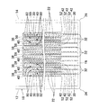
製本装置1000は、図10に示すように、多数枚のシート状ポケット22を保持するシート状ポケット保持機構1002と、表紙体18を保持する表紙体用保持機構1004と、発熱体1006(H)と、この発熱体1006(H)をシート状ポケット22と表紙体18との間に介在または抜き出し可能とするシリンダ機構(図示せず)とを備えている。
As shown in FIG. 10, the
シート状ポケット保持機構1002は、テーブル1010に固定のシート状ポケット押圧部1008と、図示しないねじやピストン等の駆動手段でテーブル1010上を可動する可動シート状ポケット押圧部1012と、固定のシート状ポケット押圧部1008と可動シート状ポケット押圧部1012とによってシート状ポケット22をクランプするように構成されている。
The sheet-like
また、表紙体用保持機構1004は、表紙体18の内面を下向きにして取り付け可能に構成されたものであり、図示しない昇降手段により上下動可能に構成されている。
The cover
発熱体1006(H)は、内部にシーズヒータ等が内蔵された板状のものであるが、発熱体1006(H)はこれに限らず、熱エネルギーを放出可能な種々の手段が考えられる。 The heating element 1006 (H) is a plate having a sheathed heater or the like built therein, but the heating element 1006 (H) is not limited to this, and various means capable of releasing heat energy are conceivable.
前記の製本装置1000を使用してファイルを製本する方法について説明する。
まず、図10に示すように、多数枚のシート状ポケット22を重合し、その重なり端面を固定のシート状ポケット押圧部1008と可動シート状ポケット押圧部1012とでクランプし、且つ、表紙体用保持機構1004により、表紙体18の内面を下側にした状態で、表紙体18を保持し、表紙体用保持機構1004を下降させてシート状ポケット群20の溶着縁32の上面と表紙体18の内面とを対向させるとともに、その間に発熱体1006(H)を介在させることができる位置まで接近させる。
そして、発熱体1006(H)を両者の間に介在させ、表紙体18の内面と第1ポケット構成シート30の溶着縁32の上部のつき合せ端縁とを同時に溶融させる。
A method of binding a file using the
First, as shown in FIG. 10, a large number of sheet-
Then, the heating element 1006 (H) is interposed between them, and the inner surface of the
その溶融温度は、ポリプロピレンの溶融温度が、120〜130℃であるため、170〜180℃前後の発熱体1006を使用して4〜5秒前後の時間で、表紙体18の内面と第1ポケット構成シート30の溶着縁32の上縁のつき合せ端縁とを同時に溶融させる。
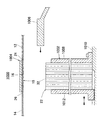
その後、表紙体18と溶着縁32との間から発熱体1006(H)を引き抜き、背表紙部16を第1ポケット構成シート30の溶着縁32に接触させて両者を接合する(図12参照)。
Since the melting temperature of polypropylene is 120 to 130 ° C., the inner surface of the
Thereafter, the heating element 1006 (H) is pulled out from between the
そして、適宜、溶着部位を冷却して、完全に表紙体18の背表紙部16の内面と第1ポケット構成シート30の溶着縁32のつき合せ端縁とを固着する。
Then, the welding portion is appropriately cooled, and the inner surface of the
実際の使用においては、第1ポケット構成シート30と第2ポケット構成シート40との間に形成された収容部80に収容される被挟体Sを、第2ポケット構成シート40の開口縁42及び第3ポケット構成シート50の開口縁52より第2ポケット構成シート40の収容部80及び第3ポケット構成シート50の収容部82に挿入し、被挟体SをA面側シート状ポケット22の収容部80とB面側のシート状ポケット22の収容部82に跨って収容する。
而して、表表紙部12と裏表紙部14とを開き、見開いた状態で、シート状ポケット22の収容部80及び収容部82に挿入された被挟体Sを閲覧できる。
そして、表表紙部12と裏表紙部14を閉じたときは、被挟体Sの幅方向における中央領域を、隣接するA面側のシート状ポケット22とB面側のシート状ポケット22との中間に位置させ、被挟体Sの折り曲げ部S1が隣接するA面側のシート状ポケット22とB面側のシート状ポケット22との中間において高さ方向に第1ポケット構成シート30の溶着縁32に沿ってのび、見開いた状態でシート状ポケット22の収容部80及び収容部82に挿入されるように構成されているので、被挟体Sの中央に正確に折り目を形成できる。
In actual use, the sandwiched body S accommodated in the
Thus, the
When the
10 ファイル
12 表表紙部
14 裏表紙部
16 背表紙部
18 表紙体
20 シート状ポケット群
22 シート状ポケット
22a 底縁部
22b 上縁部
22c 側縁部
24 表折り曲げ部
26 裏折り曲げ部
30 第1ポケット構成シート
32 溶着縁
34 底縁
36 上縁
38 側縁
40 第2ポケット構成シート
42 開口縁
44 底縁
46 上縁
48 側縁
50 第3ポケット構成シート
52 開口縁
54 底縁
56 上縁
58 側縁
80 収容部
82 収容部
1000 製本装置
1002 シート状ポケット保持機構
1004 表紙体用保持機構
1006 発熱体
1008 シート状ポケット押圧部
1010 テーブル
1012 可動シート状ポケット押圧部
S 被挟体
S1 折り曲げ部
DESCRIPTION OF
Claims (2)
表紙体は、合成樹脂シートからなる表表紙部と、裏表紙部と、前記表表紙部と裏表紙部との間に連設された背表紙部とを有し、
前記表表紙部及び裏表紙部は、表表紙部及び裏表紙部の高さ方向において上端から下端に亘って連続する直線状の表折り曲げ部及び裏折り曲げ部を介して、ほぼ直角に交差するように、背表紙部に連設され、
前記表表紙部と裏表紙部との間に連設された背表紙部は、その内側において、シート状ポケット群を構成する第1ポケット構成シートの溶着縁のつき合わせ端縁を、溶着固定され、
シート状ポケット群は、複数のシート状ポケットにより構成され、
前記シート状ポケットは、背表紙部に固着された直線状部位から上の部位の間において、柔軟に形成され、
前記各シート状ポケットは、表紙体の中間領域の背表紙部に固着された直線状部位と直交する底縁部、底縁部に相対する上縁部及び表紙体の中間領域の背表紙部に固着された直線状部位に相対する側縁部を有し、表紙体の背表紙部に溶着するための溶着縁を備えた第1ポケット構成シートと、前記第1ポケット構成シートのA面側に設けられた第2ポケット構成シートと、前記第1ポケット構成シートのB面側に設けられた第3ポケット構成シートとを備え、
前記第2ポケット構成シート及び第3ポケット構成シートは、透明性を有し、開口縁を備え、
前記第1ポケット構成シートは、平面視方形状で、溶着縁と交差する底縁と溶着縁と交差する上縁と溶着縁と相対する側縁とを備え、
前記第2ポケット構成シートは、平面視方形状であり、開口縁と交差する底縁及び該底縁と相対する上縁と、底縁及び上縁と交差する側縁とを備え、
前記第3ポケット構成シートは、平面視方形状であり、開口縁と交差する底縁及び該底縁と相対する上縁と、底縁及び上縁と交差する側縁とを備え、
前記第1ポケット構成シートは、第1ポケット構成シートの底縁と交差し且つ第1ポケット構成シートの溶着縁と並ぶ開口縁を、第1ポケット構成シートの溶着縁のつき合わせ端縁を溶着された表紙体の背表紙部に対向する位置で、隣接するシート状ポケットの第2ポケット構成シートの開口縁と第3ポケット構成シートの開口縁とが対向して開口されるように、それぞれ単独で、隣接する第1ポケット構成シートとの間に間隔をおいて溶着縁のつき合わせ端縁にて表紙体の背表紙部に固着され、
前記第2ポケット構成シートと第3ポケット構成シートとは、一枚の長尺状樹脂シートからなり、幅方向における中間領域において、底縁から上縁にかけて折り返されて、対向するように構成され、第2ポケット構成シートと第3ポケット構成シートとの対向する面の間に第1ポケット構成シートを挟み込み、第1ポケット構成シート,第2ポケット構成シート及び第3ポケット構成シートを、ポケット構成シートの底縁及び上縁を封止するように幅方向に溶着切断して、前記第2ポケット構成シートと第3ポケット構成シートとの間に挟まれた第1ポケット構成シートにおける底縁と交差し且つ溶着縁と相対する側縁に、第2ポケット構成シート及び第3ポケット構成シートの折り返されて構成された側縁が並んで固定され、
前記第2ポケット構成シート及び第3ポケット構成シートは、底縁及び上縁において、表紙体の背表紙部に溶着された溶着縁と交差する第1ポケット構成シートにおける底縁及び上縁と連続して封止されるとともに、底縁と交差し且つ第1ポケット構成シートの溶着縁と並ぶ開口縁を、第1ポケット構成シートの溶着縁を溶着された表紙体に対向する位置で、隣接するシート状ポケットの開口縁と対向して開口されるように形成され、
前記A面側の第2ポケット構成シートの開口部は、隣接するシート状ポケットのB面側の第3ポケット構成シートと近くに位置して対向し、第1ポケット構成シートと第2ポケット構成シートとの間に形成された収容部に収容される被挟体を、A面側シート状ポケットの収容部とB面側のシート状ポケットの収容部に跨って収容され、被挟体の幅方向における中央領域を隣接するA面側のシート状ポケットとB面側のシート状ポケットとの中間に位置させて、被挟体の折り曲げ部を隣接するA面側のシート状ポケットとB面側のシート状ポケットとの中間において高さ方向に第1ポケット構成シートの溶着縁に沿ってのびるように、A面側のシート状ポケットとB面側のシート状ポケットとは、第1ポケット構成シートの溶着縁において表紙体の背表紙部に固着され、
第1ポケット構成シートと第2ポケット構成シートとの間に形成された収容部に収容される被挟体が、第2ポケット構成シートの開口縁及び第3ポケット構成シートの開口縁より第2ポケット構成シートの収容部及び第3ポケット構成シートの収容部に挿入され、被挟体をA面側シート状ポケットの収容部とB面側のシート状ポケットの収容部に跨って収容され、
表表紙部と裏表紙部とを開き、見開いた状態で、シート状ポケットの収容部及び収容部に挿入された被挟体を閲覧でき、
表表紙部と裏表紙部を閉じたとき、被挟体の幅方向における中央領域を、隣接するA面側のシート状ポケットとB面側のシート状ポケットとの中間に位置させ、被挟体の折り曲げ部が隣接するA面側のシート状ポケットとB面側のシート状ポケットとの中間において高さ方向に第1ポケット構成シートの溶着縁に沿ってのび、見開いた状態でシート状ポケットのA面側の収容部及びB面側の収容部に挿入され、被挟体の中央に折り目を形成できる、見開き状クリアポケットファイル。 A facing clear pocket file comprising a cover body and a sheet-like pocket group fixed to the inner surface of the cover body in an intermediate region of the cover body,
The cover body has a front cover portion made of a synthetic resin sheet, a back cover portion, and a spine cover portion provided continuously between the front cover portion and the back cover portion,
The front cover part and the back cover part intersect each other almost at right angles through a straight front bent part and a back bent part continuous from the upper end to the lower end in the height direction of the front cover part and the back cover part. In the back cover part,
The spine cover part continuously provided between the front cover part and the back cover part is welded and fixed with the welding edge of the welding edge of the first pocket constituting sheet constituting the sheet-like pocket group on the inner side. ,
The sheet-like pocket group is composed of a plurality of sheet-like pockets,
The sheet-like pocket is formed flexibly between the upper part from the straight part fixed to the spine portion,
Each of the sheet-like pockets is formed on the bottom edge perpendicular to the straight portion fixed to the spine portion of the middle area of the cover body, the upper edge portion opposed to the bottom edge portion, and the spine portion of the middle area of the cover body. A first pocket constituting sheet having a side edge portion opposed to the fixed linear portion and having a welding edge for welding to the spine portion of the cover body; and on the A side of the first pocket constituting sheet A second pocket constituting sheet provided, and a third pocket constituting sheet provided on the B surface side of the first pocket constituting sheet,
The second pocket constituting sheet and the third pocket constituting sheet have transparency and have an opening edge,
The first pocket-constituting sheet has a square shape in plan view, and includes a bottom edge that intersects the welding edge, an upper edge that intersects the welding edge, and a side edge that faces the welding edge,
The second pocket-constituting sheet has a shape in plan view, and includes a bottom edge that intersects the opening edge, a top edge that faces the bottom edge, and a side edge that intersects the bottom edge and the top edge,
The third pocket-constituting sheet has a planar shape, and includes a bottom edge that intersects with the opening edge, a top edge that faces the bottom edge, and a side edge that intersects the bottom edge and the top edge,
The first pocket constituting sheet has an opening edge that intersects a bottom edge of the first pocket constituting sheet and is aligned with a welding edge of the first pocket constituting sheet, and a joining edge of the welding edge of the first pocket constituting sheet is welded. The opening edge of the second pocket constituting sheet and the opening edge of the third pocket constituting sheet of the adjacent sheet-like pockets are opened independently at positions facing the spine portion of the cover body. Affixed to the spine portion of the cover body at the butt edge of the welding edge with a gap between the adjacent first pocket constituting sheets,
The second pocket constituting sheet and the third pocket constituting sheet are composed of one long resin sheet, and are configured to be folded back from the bottom edge to the upper edge in the intermediate region in the width direction, The first pocket constituting sheet is sandwiched between the opposing surfaces of the second pocket constituting sheet and the third pocket constituting sheet, and the first pocket constituting sheet, the second pocket constituting sheet, and the third pocket constituting sheet are placed on the pocket constituting sheet. Cutting and welding in the width direction so as to seal the bottom edge and the top edge, intersecting the bottom edge of the first pocket constituting sheet sandwiched between the second pocket constituting sheet and the third pocket constituting sheet; The side edges formed by folding back the second pocket constituting sheet and the third pocket constituting sheet are fixed side by side on the side edges facing the welding edge,
The second pocket constituting sheet and the third pocket constituting sheet are continuous with the bottom edge and the top edge in the first pocket constituting sheet intersecting the weld edge welded to the spine cover portion of the cover body at the bottom edge and the top edge. And an opening edge that intersects the bottom edge and is aligned with the welding edge of the first pocket constituting sheet at a position facing the cover body to which the welding edge of the first pocket constituting sheet is welded. Formed so as to be opposed to the opening edge of the pocket,
The opening of the second pocket constituting sheet on the A surface side is located close to and opposed to the third pocket constituting sheet on the B surface side of the adjacent sheet-like pocket, and the first pocket constituting sheet and the second pocket constituting sheet. The sandwiched body housed in the housing part formed between the housing part is accommodated across the housing part of the A-side sheet-like pocket and the seat part of the B-side sheet-like pocket, and the width direction of the sandwiched body The central region is positioned between the adjacent A-side sheet-like pocket and the B-side sheet-like pocket, and the bent portion of the sandwiched body is placed between the adjacent A-side sheet-like pocket and the B-side side. The sheet-like pocket on the A side and the sheet-like pocket on the B-side are formed in the middle of the sheet-like pocket in the height direction along the weld edge of the first pocket-constituting sheet. Cover at the welding edge Is fixed to the back cover part,
The sandwiched body accommodated in the accommodating portion formed between the first pocket constituting sheet and the second pocket constituting sheet is the second pocket from the opening edge of the second pocket constituting sheet and the opening edge of the third pocket constituting sheet. It is inserted into the accommodating part of the constituent sheet and the accommodating part of the third pocket constituent sheet, and the sandwiched body is accommodated across the accommodating part of the A-side sheet-like pocket and the accommodating part of the B-side sheet-like pocket,
Open the front cover part and the back cover part, and in a state of opening it, the storage part of the sheet-like pocket and the sandwiched body inserted in the storage part can be viewed,
When the front cover portion and the back cover portion are closed, the center region in the width direction of the sandwiched body is positioned between the adjacent A-side sheet-like pocket and the B-side sheet-like pocket, In the middle of the A-side sheet-like pocket and the B-side-side sheet-like pocket adjacent to each other, the folding portion extends along the welding edge of the first pocket-constituting sheet in the height direction, A double-sided clear pocket file that is inserted into the A-side storage part and the B-side storage part and can form a crease at the center of the sandwiched body .
(一)表紙体は、合成樹脂シートからなる表表紙部と、裏表紙部と、前記表表紙部と裏表紙部との間に連設された背表紙部とを有し、
前記表表紙部及び裏表紙部は、表表紙部及び裏表紙部の高さ方向において上端から下端に亘って連続する直線状の表折り曲げ部及び裏折り曲げ部を介して、ほぼ直角に交差するように、背表紙部に連設され、
前記表表紙部と裏表紙部との間に連設された背表紙部は、その内側において、シート状ポケット群を構成する第1ポケット構成シートの溶着縁のつき合わせ端縁を、溶着固定され、
シート状ポケット群は、複数のシート状ポケットにより構成され、
前記シート状ポケットは、背表紙部に固着された直線状部位から上の部位の間において、柔軟に形成され、
(二)シート状ポケット群を、下記(a),(b),(c)及び(d)の複数のシート状ポケットにより構成するために、
(a)前記各シート状ポケットは、表紙体の中間領域の背表紙部に固着された直線状部位と直交する底縁部、底縁部に相対する上縁部及び表紙体の中間領域の背表紙部に固着された直線状部位に相対する側縁部を有し、表紙に溶着するための溶着縁を備えた第1ポケット構成シートと、透明性を有し、開口縁を備えた、第2ポケット構成シートと、第3ポケット構成シートとを有し、
(b)第1ポケット構成シートは、平面視方形状で、溶着縁と交差する底縁と溶着縁と交差する上縁と溶着縁と相対する側縁とを備え、
(c)第2ポケット構成シートは、平面視方形状であり、開口縁と交差する底縁及び該底縁と相対する上縁と、底縁及び上縁と交差する側縁とを備え、
(d)第3ポケット構成シートは、平面視方形状であり、開口縁と交差する底縁及び該底縁と相対する上縁と、底縁及び上縁と交差する側縁とを備え、
(三)一枚の長尺状樹脂シートを折り返し、対向する第2ポケット構成シートと第3ポケット構成シートとを構成し、
(四)第2ポケット構成シートと第2ポケット構成シートとの対向する面の間に第1ポケット構成シートを挟み込み、ポケット構成シートの底縁及び上縁を封止するように、該第1ポケット構成シート,第2ポケット構成シート及び第3ポケット構成シートを幅方向に溶着切断して、
第2ポケット構成シート及び第3ポケット構成シートを、溶着縁と交差する第1ポケット構成シートにおける底縁及び上縁において、第1ポケット構成シートの底縁及び上縁と連続して封止するとともに、底縁と交差し且つ第1ポケット構成シートの溶着縁と並ぶ開口縁を、第1ポケット構成シートの溶着縁を溶着された表紙体に対向する位置で、隣接するシート状ポケットの第2ポケット構成シートの開口縁と第3ポケット構成シートの開口縁とが対向して開口されるように形成し、
(五)第1ポケット構成シートの底縁と交差し且つ第1ポケット構成シートの溶着縁と並ぶ開口縁を、第1ポケット構成シートの溶着縁を溶着された表紙体の背表紙部に対向する位置で、隣接するシート状ポケットの第2ポケット構成シートの開口縁と第3ポケット構成シートの開口縁とが対向して開口されるように、前記各シート状ポケットを構成する第1ポケット構成シートを、それぞれ単独で、表紙に溶着するための溶着縁のつき合わせ端縁により、隣接する第1ポケット構成シートとの間に間隔をおいて溶着縁のつき合わせ端縁にて表紙体の背表紙部に固着し、
(六)A面側の第2ポケット構成シートの開口部は、隣接するシート状ポケットのB面側の第3ポケット構成シートと近くに位置して対向し、第1ポケット構成シートと第2ポケット構成シートとの間に形成された収容部に収容される被挟体を、A面側シート状ポケットの収容部とB面側のシート状ポケットの収容部に跨って収容され、被挟体の幅方向における中央領域を隣接するA面側のシート状ポケットとB面側のシート状ポケットとの中間に位置させて、被挟体の折り曲げ部を隣接するA面側のシート状ポケットとB面側のシート状ポケットとの中間において高さ方向に第1ポケット構成シートの溶着縁に沿ってのびるように、A面側のシート状ポケットとB面側のシート状ポケットとは、第1ポケット構成シートの溶着縁のつき合わせ端縁において表紙体の背表紙部に固着し、
(七)第1ポケット構成シートと第2ポケット構成シートとの間に形成された収容部に収容される被挟体が、第2ポケット構成シートの開口縁及び第3ポケット構成シートの開口縁より第2ポケット構成シートの収容部及び第3ポケット構成シートの収容部に挿入され、被挟体をA面側シート状ポケットの収容部とB面側のシート状ポケットの収容部に跨って収容され、
表表紙部と裏表紙部とを開き、見開いた状態で、シート状ポケットの収容部及び収容部に挿入された被挟体を閲覧でき、
表表紙部と裏表紙部を閉じたとき、被挟体の幅方向における中央領域を、隣接するA面側のシート状ポケットとB面側のシート状ポケットとの中間に位置させ、被挟体の折り曲げ部が隣接するA面側のシート状ポケットとB面側のシート状ポケットとの中間において高さ方向に第1ポケット構成シートの溶着縁に沿ってのび、見開いた状態でシート状ポケットのA面側の収容部及びB面側の収容部に挿入され、被挟体の中央に折り目を形成できる、見開き状クリアポケットファイルの製造方法。 A method for producing a spread-like clear pocket file comprising a cover body and a sheet-like pocket group having transparency fixed to the inner surface of the cover body in an intermediate region of the cover body,
(1) The front cover body has a front cover portion made of a synthetic resin sheet, a back cover portion, and a back cover portion continuously provided between the front cover portion and the back cover portion,
The front cover part and the back cover part intersect each other almost at right angles through a straight front bent part and a back bent part continuous from the upper end to the lower end in the height direction of the front cover part and the back cover part. In the back cover part,
The spine cover part continuously provided between the front cover part and the back cover part is welded and fixed with the welding edge of the welding edge of the first pocket constituting sheet constituting the sheet-like pocket group on the inner side. ,
The sheet-like pocket group is composed of a plurality of sheet-like pockets ,
The sheet-like pocket is formed flexibly between the upper part from the straight part fixed to the spine portion,
( 2 ) In order to configure the sheet-like pocket group by a plurality of sheet-like pockets of the following (a), (b), (c) and (d),
(A) Each of the sheet-like pockets includes a bottom edge perpendicular to the straight portion fixed to the spine portion of the middle area of the cover body, an upper edge portion opposed to the bottom edge, and a spine of the middle area of the cover body. A first pocket-constituting sheet having a side edge portion opposed to the linear portion fixed to the cover portion and having a welding edge for welding to the cover portion, and having transparency and an opening edge; A two-pocket constituent sheet and a third pocket-constituting sheet;
(B) The first pocket constituting sheet has a shape in plan view, and includes a bottom edge that intersects with the welding edge, an upper edge that intersects with the welding edge, and a side edge that faces the welding edge,
(C) The second pocket-constituting sheet has a shape in plan view, and includes a bottom edge that intersects the opening edge, a top edge that faces the bottom edge, and a side edge that intersects the bottom edge and the top edge,
(D) The third pocket-constituting sheet has a shape in plan view, and includes a bottom edge that intersects the opening edge, a top edge that faces the bottom edge, and a side edge that intersects the bottom edge and the top edge,
( 3 ) Folding one long resin sheet to constitute a second pocket constituting sheet and a third pocket constituting sheet facing each other,
( 4 ) The first pocket so that the first pocket constituent sheet is sandwiched between the opposing surfaces of the second pocket constituent sheet and the second pocket constituent sheet, and the bottom edge and the upper edge of the pocket constituent sheet are sealed. Weld and cut the component sheet, the second pocket component sheet and the third pocket component sheet in the width direction,
The second pocket constituting sheet and the third pocket constituting sheet are continuously sealed with the bottom edge and the upper edge of the first pocket constituting sheet at the bottom edge and the upper edge of the first pocket constituting sheet intersecting the welding edge. An opening edge that intersects the bottom edge and is aligned with the welding edge of the first pocket-constituting sheet is located at a position facing the cover body on which the welding edge of the first pocket-constituting sheet is welded, and the second pocket of the adjacent sheet-like pocket The opening edge of the component sheet and the opening edge of the third pocket component sheet are formed so as to face each other,
( 5 ) The opening edge that intersects the bottom edge of the first pocket constituent sheet and is aligned with the welding edge of the first pocket constituent sheet is opposed to the spine portion of the cover body to which the welding edge of the first pocket constituent sheet is welded. The first pocket constituting sheet constituting each of the sheet shaped pockets so that the opening edge of the second pocket constituting sheet and the opening edge of the third pocket constituting sheet of the adjacent sheet-like pocket are opened facing each other at the position. , Each independently, with a welding edge abutting edge for welding to the cover, with a gap between the adjoining first pocket forming sheets and a welding edge abutting edge on the back cover of the cover body Fixed to the part ,
( 6 ) The opening of the second pocket constituting sheet on the A side is located close to and opposed to the third pocket constituting sheet on the B side of the adjacent sheet-like pocket, and the first pocket constituting sheet and the second pocket The sandwiched body accommodated in the accommodating portion formed between the constituent sheets is accommodated across the accommodating portion of the A-side sheet-like pocket and the accommodating portion of the B-side sheet-like pocket. The central region in the width direction is positioned between the adjacent A-side sheet-like pocket and the B-side sheet-like pocket, and the folded portion of the sandwiched body is adjacent to the A-side sheet-like pocket and B-side. The sheet-like pocket on the A side and the sheet-like pocket on the B-side are formed in the first pocket so as to extend along the welding edge of the first pocket-forming sheet in the height direction in the middle of the sheet-like pocket on the side. match-welding edge of the sheet Fixed to the spine part of the cover body at the edge,
(7) From the opening edge of the second pocket constituting sheet and the opening edge of the third pocket constituting sheet, the sandwiched body accommodated in the accommodating portion formed between the first pocket constituting sheet and the second pocket constituting sheet It is inserted into the accommodating portion of the second pocket constituting sheet and the accommodating portion of the third pocket constituting sheet, and the sandwiched object is accommodated across the accommodating portion of the A-side sheet-like pocket and the accommodating portion of the B-side sheet-like pocket. ,
Open the front cover part and the back cover part, and in a state of opening it, the storage part of the sheet-like pocket and the sandwiched body inserted in the storage part can be viewed,
When the front cover portion and the back cover portion are closed, the center region in the width direction of the sandwiched body is positioned between the adjacent A-side sheet-like pocket and the B-side sheet-like pocket, In the middle of the A-side sheet-like pocket and the B-side-side sheet-like pocket adjacent to each other, the folding portion extends along the welding edge of the first pocket-constituting sheet in the height direction, A method for producing a two-sided clear pocket file , which is inserted into a storage part on the A side and a storage part on the B side, and can form a crease at the center of the sandwiched body .
Priority Applications (1)
| Application Number | Priority Date | Filing Date | Title |
|---|---|---|---|
| JP2011046683A JP5659049B2 (en) | 2011-03-03 | 2011-03-03 | Facing clear pocket file and manufacturing method thereof |
Applications Claiming Priority (1)
| Application Number | Priority Date | Filing Date | Title |
|---|---|---|---|
| JP2011046683A JP5659049B2 (en) | 2011-03-03 | 2011-03-03 | Facing clear pocket file and manufacturing method thereof |
Publications (2)
| Publication Number | Publication Date |
|---|---|
| JP2012183662A JP2012183662A (en) | 2012-09-27 |
| JP5659049B2 true JP5659049B2 (en) | 2015-01-28 |
Family
ID=47014196
Family Applications (1)
| Application Number | Title | Priority Date | Filing Date |
|---|---|---|---|
| JP2011046683A Active JP5659049B2 (en) | 2011-03-03 | 2011-03-03 | Facing clear pocket file and manufacturing method thereof |
Country Status (1)
| Country | Link |
|---|---|
| JP (1) | JP5659049B2 (en) |
Families Citing this family (1)
| Publication number | Priority date | Publication date | Assignee | Title |
|---|---|---|---|---|
| JP6143720B2 (en) * | 2014-09-12 | 2017-06-07 | 株式会社リヒトラブ | Pocket for files |
Family Cites Families (5)
| Publication number | Priority date | Publication date | Assignee | Title |
|---|---|---|---|---|
| JPS6028638Y2 (en) * | 1982-10-01 | 1985-08-30 | 株式会社キングジム | Double wing insertion file |
| JPH02265798A (en) * | 1989-04-06 | 1990-10-30 | Nippon Fuairu Kogyo Kk | Production of two-wing insert file sheet |
| JPH0681776U (en) * | 1993-05-11 | 1994-11-22 | 株式会社フェイス | Bookbinding for recording and sheet material for recording |
| JPH07329472A (en) * | 1994-06-09 | 1995-12-19 | Tomoda Giken Kogyo Kk | Document arranging file |
| JP3139131U (en) * | 2007-11-16 | 2008-01-31 | 株式会社ソノ | Document file |
-
2011
- 2011-03-03 JP JP2011046683A patent/JP5659049B2/en active Active
Also Published As
| Publication number | Publication date |
|---|---|
| JP2012183662A (en) | 2012-09-27 |
Similar Documents
| Publication | Publication Date | Title |
|---|---|---|
| JP5659049B2 (en) | Facing clear pocket file and manufacturing method thereof | |
| JP2009214923A (en) | Packaged food, sheet fixing device, and sheet fixing method | |
| JPH1178331A (en) | Filing tool | |
| JP2009029100A (en) | Document holder | |
| JP3165736U (en) | Filing tools | |
| JP5602068B2 (en) | File and manufacturing method thereof | |
| JP4544547B1 (en) | Filing tools | |
| JPH08290694A (en) | Production of filing book | |
| JP3184301U (en) | Clear file book | |
| JP2020040305A (en) | Document holder and manufacturing method for document holder | |
| JP3177421U (en) | Pen holder and cover with pen holder | |
| TW201141713A (en) | Card jacket and notebook, file folder having the same | |
| WO2015186826A1 (en) | File | |
| JP2003159883A (en) | Cover and file | |
| JP3143860U (en) | Thin file pocket reinforcement structure | |
| JP2011201114A (en) | File and method of manufacturing the same | |
| JP3196420U (en) | Cover | |
| JP3696847B2 (en) | Folder and manufacturing method thereof | |
| JP4637144B2 (en) | Pocket file | |
| JP2008279748A (en) | Book-making structure for files | |
| JP2008126635A (en) | File for office works, and method of manufacturing the same | |
| JP2010083017A (en) | Bookbinding booklet and method of manufacturing the same | |
| JP5990146B2 (en) | Pen holder and cover with pen holder | |
| JP6143720B2 (en) | Pocket for files | |
| JPH08132758A (en) | Bookbinding tool |
Legal Events
| Date | Code | Title | Description |
|---|---|---|---|
| A977 | Report on retrieval |
Free format text: JAPANESE INTERMEDIATE CODE: A971007 Effective date: 20130218 |
|
| A131 | Notification of reasons for refusal |
Free format text: JAPANESE INTERMEDIATE CODE: A131 Effective date: 20130312 |
|
| A521 | Written amendment |
Free format text: JAPANESE INTERMEDIATE CODE: A523 Effective date: 20130508 |
|
| A131 | Notification of reasons for refusal |
Free format text: JAPANESE INTERMEDIATE CODE: A131 Effective date: 20140304 |
|
| A521 | Written amendment |
Free format text: JAPANESE INTERMEDIATE CODE: A523 Effective date: 20140428 |
|
| TRDD | Decision of grant or rejection written | ||
| A01 | Written decision to grant a patent or to grant a registration (utility model) |
Free format text: JAPANESE INTERMEDIATE CODE: A01 Effective date: 20141111 |
|
| A61 | First payment of annual fees (during grant procedure) |
Free format text: JAPANESE INTERMEDIATE CODE: A61 Effective date: 20141201 |
|
| R150 | Certificate of patent or registration of utility model |
Ref document number: 5659049 Country of ref document: JP Free format text: JAPANESE INTERMEDIATE CODE: R150 |
|
| R250 | Receipt of annual fees |
Free format text: JAPANESE INTERMEDIATE CODE: R250 |
|
| R250 | Receipt of annual fees |
Free format text: JAPANESE INTERMEDIATE CODE: R250 |