JP3165736U - Filing tools - Google Patents
Filing tools Download PDFInfo
- Publication number
- JP3165736U JP3165736U JP2010007618U JP2010007618U JP3165736U JP 3165736 U JP3165736 U JP 3165736U JP 2010007618 U JP2010007618 U JP 2010007618U JP 2010007618 U JP2010007618 U JP 2010007618U JP 3165736 U JP3165736 U JP 3165736U
- Authority
- JP
- Japan
- Prior art keywords
- sheet
- main body
- body sheet
- filing tool
- Prior art date
- Legal status (The legal status is an assumption and is not a legal conclusion. Google has not performed a legal analysis and makes no representation as to the accuracy of the status listed.)
- Expired - Fee Related
Links
Images


Abstract
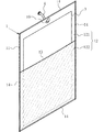
【課題】製造コストを上げずに、上又は下どちらかでもパンフレット類類を収納できるファイリング用具を提供する。【解決手段】紙製又は樹脂製の本体シート11の片面にポケットを形成したファイリング用具1において、本体シート11の片面に前記本体シート11と同形状である紙製又は樹脂製のポケットシート12,13を積層し、本体シート11及びポケットシート12を周縁で接合する。さらに、ポケットシート12の上下中間位置に左右に延びる切れ込み13を設けて、前記切れ込み13を挟んだ上下一対のポケット121,122を形成してファイリング用具1を形成する。【選択図】図1The present invention provides a filing tool capable of storing pamphlets either at the top or bottom without increasing the manufacturing cost. In a filing tool 1 in which a pocket is formed on one side of a paper or resin main body sheet 11, a paper or resin pocket sheet 12 having the same shape as the main body sheet 11 is formed on one side of the main body sheet 11. 13 are laminated and the main body sheet | seat 11 and the pocket sheet | seat 12 are joined by a periphery. Furthermore, the filing tool 1 is formed by providing a notch 13 extending in the left-right direction at the upper and lower intermediate positions of the pocket sheet 12 and forming a pair of upper and lower pockets 121 and 122 sandwiching the notch 13. [Selection] Figure 1
Description
本考案は、パンフレット類を収納するポケットを有するファイリング用具に関する。 The present invention relates to a filing tool having a pocket for storing brochures.
紙製又は樹脂製の本体シートの片面又は両面や、二つ折り以上に折り畳める前記本体シートの内側又は外側の一方又は双方に、本体シートより小さい別体の紙製又は樹脂製のポケットシートや折り返した本体シートを、ポケット形状に縁部を固定してポケットを形成したファイリング用具は、前記ポケットにパンフレット類(例えば商品案内又は説明用の冊子等)を収納して利用される。こうしたファイリング用具は、安価かつ取り扱いが簡便なことから多用されている(特許文献1及び特許文献2)。
One or both sides of the main sheet made of paper or resin, or one or both of the inner and outer sides of the main sheet that can be folded into two or more folds. A filing tool in which a pocket is formed by fixing the edge of a main body sheet in a pocket shape is used by storing pamphlets (for example, a product guide or a booklet for explanation) in the pocket. Such filing tools are widely used because they are inexpensive and easy to handle (
特許文献1は、折り畳み自在とした紙製の本体シート(紙化粧表紙)の内側に、2枚以上の紙製のポケットシートを複数枚重ねてそれぞれ縁部を固定することにより、複数のポケットを形成したファリング用具(健康、生活ファイル)を開示する(特許文献1・[請求項1])。ポケットは、それぞれマチ付きであり、前記マチの深さを変えて、それぞれにパンフレット類を収納できるようにしている。
特許文献2は、折り畳める紙製又は樹脂製の本体シート(合成樹脂製材、特許文献2・[請求項8])の内側又は外側の少なくとも一方にポケット(ポケット状の保管部)を形成するファイリング用具(介護保険用収納ファイル)を開示する(特許文献2・[請求項1])。ポケットを形成する素材は100μm以上の厚みとし、ホットスタンピング(箔押し)することを明示している(特許文献2・[請求項10])。
従来のファイリング用具は、形成されたポケットに対してパンフレット類を収納する方向が決まっていた。例えば二つ折りの紙製又は樹脂製の本体シートからなるファイリング用具において、開いた本体シートの左内側にポケットを設け、前記ポケットに左上から左下に向けてパンフレット類を収納させる場合、前記ポケットに左下から左上に向けてパンフレット類を収納させることはできず、ポケットを開いた本体シートの右内側に持ってくると、ポケットが逆さになり、パンフレット類を収納させることができなかった。 In the conventional filing tool, the direction in which the pamphlets are stored in the formed pocket is determined. For example, in a filing tool consisting of a folded paper or resin main body sheet, when a pocket is provided on the left inner side of the opened main body sheet, and brochures are stored in the pocket from the upper left to the lower left, the pocket has a lower left Brochures could not be stored from the top to the upper left, and when the pockets were brought to the right inside of the main body sheet, the pockets were inverted and could not be stored.
こうしたことから、左内側にポケットを形成したファイリング用具と右内側にポケットを形成したファイリング用具とが必要であれば、それぞれ別に用意しなければならなかった。これでは、大量生産による安価になるファイリング用具の経済性が損なわれるし、利用者は左右内側のどちらにポケットがあるかを判別して利用しなければならず、ファイリング用具の利便性も損なわれてしまう。そこで、製造コストを上げずに、上又は下どちらからでもパンフレット類を収納できるファイリング用具を提供するため、検討した。 For this reason, if a filing tool having a pocket on the left inner side and a filing tool having a pocket on the right inner side are required, they had to be prepared separately. This impairs the economics of filing tools that are inexpensive due to mass production, and the user must determine which pockets are on the inside of the left and right sides before using them. End up. Therefore, in order to provide a filing tool capable of storing brochures from above or below without increasing the manufacturing cost, it was studied.
検討の結果考案したものが、紙製又は樹脂製の本体シートの片面又は両面にポケットを形成したファイリング用具において、本体シートの片面又は両面に前記本体シートと同形状である紙製又は樹脂製のポケットシートを積層し、本体シート及びポケットシートを周縁で接合すると共に、ポケットシートの上下中間位置に左右に延びる切れ込みを設けて、前記切れ込みを挟んだ上下一対のポケットを形成したことを特徴とするファイリング用具である。 Invented as a result of the study, in a filing tool in which a pocket is formed on one or both sides of a paper or resin main body sheet, it is made of paper or resin having the same shape as the main body sheet on one or both sides of the main body sheet. The pocket sheets are laminated, the main body sheet and the pocket sheet are joined at the periphery, and a notch extending left and right is provided at the upper and lower intermediate positions of the pocket sheet to form a pair of upper and lower pockets sandwiching the notch. A filing tool.
「ポケットシートの上下中間位置に左右に延びる切れ込みを設け」るとは、ポケットシートの上端又は下端以外であればどの位置でもよく、全体として左右方向に延在する切れ込みを設けることを意味する。これから、切れ込みは、全体が真っすぐに左右方向に延びる単なる直線のほか、全体として左右方向に延びると見ることのできる曲線や波線でもよく、また一定の幅でベルト状にポケットシートの一部を切除した構成でもよい。本体シート及びポケットシートが縦長の長方形であれば、切れ込みはポケットシートを短辺方向に延びる。切れ込みの長さは、短辺方向に横断する長さが好ましいが、短辺より短くても構わない。 “Providing a slit extending in the left-right direction at the upper and lower intermediate positions of the pocket sheet” means any position other than the upper end or the lower end of the pocket sheet, and means providing a slit extending in the left-right direction as a whole. From now on, the cut may be a simple straight line extending in the left-right direction as a whole, or a curve or wavy line that can be seen as extending in the left-right direction as a whole, and a part of the pocket sheet is cut out in a belt shape with a certain width. The configuration may be also possible. If the main body sheet and the pocket sheet are vertically long rectangles, the cut extends the pocket sheet in the short side direction. The length of the cut is preferably a length that crosses in the short side direction, but may be shorter than the short side.
紙製又は樹脂製の本体シートの片面又は両面にポケットを形成したファイリング用具の前記本体シート及びポケットシートが縦長の長方形で、本体シートに積層するポケットシートが別体であれば、4辺を接合する。また、本体シートを折り返した半分をポケットシートとした場合、折り返し縁を除く3辺を接合する。この場合、本体シートとポケットシートとは同素材となる。このほか、樹脂製の筒体を平坦化して、重なる一方を本体シート、残る他方をポケットシートとして、開放された2辺を接合する。 If the main body sheet and pocket sheet of a filing tool in which pockets are formed on one or both sides of a paper or resin main body sheet are vertically long and the pocket sheets stacked on the main body sheet are separate, the four sides are joined. To do. Moreover, when the half which turned up the main body sheet | seat is used as a pocket sheet | seat, 3 sides except a folding | turning edge are joined. In this case, the main body sheet and the pocket sheet are the same material. In addition, the resin cylinder is flattened, and the two open sides are joined using the overlapping one as a main body sheet and the other as a pocket sheet.
また、二つ折り以上に折り畳める前記本体シートの内側又は外側の一方又は双方にポケットを形成したファイリング用具において、本体シートの内側又は外側の一方又は双方に本体シートと同形状である紙製又は樹脂製のポケットシートを積層し、本体シート及びポケットシートを周縁で接合すると共に、ポケットシートの上下中間位置に左右に延びる切れ込みを設けて、前記切れ込みを挟んだ上下一対のポケットを形成したことを特徴とするファイリング用具もできる。本体シート及びポケットシートが横長の長方形であれば、切れ込みはポケットシートを長辺方向に延び、折り畳み縁を接合して分断される。切れ込みの長さは、長辺方向に横断する長さが好ましいが、長辺より短くても構わない。 In addition, in the filing tool in which a pocket is formed on one or both of the inside and outside of the main body sheet that can be folded in two or more folds, it is made of paper or resin that has the same shape as the main body sheet on one or both of the inside and outside of the main body sheet. The pocket sheet is laminated, the main body sheet and the pocket sheet are joined at the periphery, and a slit extending in the left and right directions is provided at the upper and lower intermediate positions of the pocket sheet to form a pair of upper and lower pockets sandwiching the slit. You can also use filing tools. If the main body sheet and the pocket sheet are horizontally long rectangles, the cuts are divided by extending the pocket sheet in the long side direction and joining the folding edges. The length of the cut is preferably a length that crosses in the long side direction, but may be shorter than the long side.
二つ折り以上に折り畳める前記本体シートの内側又は外側の一方又は双方にポケットを形成したファイリング用具の本体シート及びポケットシートが横長の長方形で、本体シートに積層するポケットシートが別体であれば、4辺及び折り畳み縁を接合する。また、本体シートを折り返した半分をポケットシートとした場合、折り返し縁を除く3辺及び折り畳み縁を接合する。この場合、本体シートとポケットシートとは同素材となる。このほか、樹脂製の筒体を平坦化して、重なる一方を本体シート、残る他方をポケットシートとして、開放された2辺及び折り畳み縁を接合する。 If the main body sheet and the pocket sheet of the filing tool in which a pocket is formed on one or both of the inner and outer sides of the main body sheet that can be folded in two or more are horizontally long rectangles, and the pocket sheet laminated on the main body sheet is a separate body, 4 Join sides and folding edges. Moreover, when the half which turned up the main body sheet | seat is used as a pocket sheet | seat, three sides and folding edges except a folding edge are joined. In this case, the main body sheet and the pocket sheet are the same material. In addition, the resin cylinder is flattened, and the two open sides and the folding edge are joined using the overlapping one as the main body sheet and the remaining as the pocket sheet.
本考案により、ファイリング用具の向きに関係なく、上下一対のポケットいずれかに上又は下どちらかでもパンフレット類を収納できるようになり、ファイリング用具としての利便性を高めることができる。 According to the present invention, it becomes possible to store pamphlets in either the upper or lower pair of pockets regardless of the orientation of the filing tool, and the convenience as a filing tool can be enhanced.
本考案を実施するための形態について図を参照しながら説明する。本考案は、例えば図1〜図3に見られるように、折り畳みのないファイリング用具1に適用できる。本例のファイリング用具1は、A4サイズのパンフレット類3より一回り大きな樹脂製の本体シート11の片面に前記本体シート11(図1及び図3中、図示の便宜上、ファイリング用具1の側縁を指して符号を付している)と同形状である樹脂製のポケットシート12を積層してそれぞれの周縁を融着ライン14で接合し、ポケットシートの上下中間位置に切れ込み13を設け、切れ込み13を挟んだ上下一対のポケット121,122を形成している。
DESCRIPTION OF EMBODIMENTS Embodiments for carrying out the present invention will be described with reference to the drawings. The present invention can be applied to an
本例のファイリング用具1は、ポケットシート12の高さ(図1中上下長さ)を4:6に分けた位置に直線状の切れ込み13を設け、内部が相対的に浅い上のポケット121と、内部が相対的に深い下のポケット122とを上下一対で形成している。本例の切れ込み13は、ポケットシート12を横断する長さで、両端が本体シート11及びポケットシート12を周縁で接合する融着ライン14により封止されている。各図では、下のポケット122にハッチングを付して、上のポケット121と区別している。このほか、本例のファイリング用具1は、長辺の一方に沿ってバインダー孔15を設けている。
The
本例のファイリング用具1において、バインダー孔15を左に並べたとき、パンフレット類3は、図1に見られるように、上のポケット121の外側に宛てがい、切れ込み13から下のポケット122の内側に差し込み、下のポケット122に下半分を収納する。ここで、ファイリング用具1を上下逆にしてバインダー孔15を右に並べると、パンフレット類3は、図3に見られるように、下のポケット122の外側に宛てがい、切れ込み13から上のポケット121の内側に差し込み、上のポケット121に下半分を収納する。このように、バインダー孔15の並びに関係なく、パンフレット類3は同じ向き、すなわち上から下に向けて各ポケット121,122に収納できる。
In the
本考案のファイリング用具1は、紙製又は樹脂製の本体シート11とポケットシート12から構成されているため、バインダー孔15のように、容易に加工できるため、本例のバインダー孔15を設けた構成のほか、例えば図4に見られるように、短辺の一方又は双方に吊り下げ孔17を設けて、パンフレット類3を収納した状態でフック4に吊り下げることもできる。後述のように(図5及び図6参照)、パンフレット類3は、上のポケット121及び下のポケット122双方に差し込んで収納すれば、ファイリング用具1を吊り下げて使用しても、パンフレット類3がファイリング用具1から落ちる虞をなくすことができる。また、パンフレット類3を収納した状態で切れ込み13を塞げば、フィアリング用具1をパンフレット類3の封筒として利用できる。この場合、切れ込み13に対して開閉自在なフラップを付加するとよい。
Since the
本例のファイリング用具1は、本体シート11及びポケットシート12が縦長の長方形で、本体シート11に積層するポケットシート12が別体であれば、それぞれのロールから繰り出された本体シート11とポケットシート12とを繰出方向に重ねて側縁を融着(熱融着や超音波融着)して繰出方向に延びる袋体を形成し、本体シート11とポケットシート12とを一体に繰出方向に分断すると同時に分断縁を融着して四方が閉じた袋体を形成した後、ポケットシート12のみに切れ込み13を設けて上のポケット121及び下のポケット122を形成する手順で製造することができる。
In the
上記製造手順において、ロールから繰り出されたポケットシート12は、同じくロールから繰り出された本体シート11に重ねる前に切れ込み13を設けてもよいし、本体シート11に重ねた後、側縁を融着すると同時に切れ込み13を設けてもよい。また、予めファイリング用具1の大きさに形成された本体シート11とポケットシート12とを重ねて周縁を融着し、切れ込み13を設けてもよい。本体シート11又はポケットシート12は、着色された不織布や紙を樹脂フィルムでラミネートして構成してもよい。本体シート11やポケットシート12が紙製の場合、側縁又は周縁は融着でなく、接着となる。
In the above manufacturing procedure, the
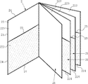
二つ折りのファイリング用具2は、図5及び図6に見られるように、A4サイズのパンフレット類3の2枚分より一回り大きく、左右中間で二つ折りする樹脂製の本体シート21の内側に、前記本体シート21と同形状である樹脂製のポケットシート22を積層してそれぞれの周縁を融着ライン27で接合し、ポケットシート22の上下中間位置にベルト状の切れ込み26を設け、前記切れ込み26を挟んだ上下一対のポケット221,222,223,224を内側左右に計4個形成している。
As shown in FIG. 5 and FIG. 6, the
本例のファイリング用具2は、ポケットシート22の高さ(図1中上下長さ)を4:6に分けた位置に左右方向に延在する上下に幅のある切れ込み26、すなわちベルト状の切れ込み26を設け、内部が相対的に浅い左内側上のポケット221及び右内側上のポケット223と、内部が相対的に深い左内側下のポケット222及び右内側下のポケット224とを上下一対で、内側左右それぞれに形成している。本例のファイリング用具2は、折り畳み縁に沿って融着ライン24を設け、左右のポケット221,223(222,224)を分離している。各図では、左内側下のポケット222及び右内側下のポケット224にハッチングを付して、左内側上のポケット221及び右内側上のポケット223と区別している。
The
本例のファイリング用具2を開いて左内側下のポケット222及び右内側下のポケット224を下にしたとき、パンフレット類3は、図5に見られるように、左内側上のポケット221の外側に宛てがい、切れ込み26から左内側下のポケット222の内側に差し込み、下半分を収納する。パンフレット類3は、例えば右内側下のポケット224に下半分を差し込んだ後、更に右内側上のポケット223に上半分を差し込んで、上下がそれぞれ右内側上のポケット223及び右内側下のポケット224に押さえ込まれた格好で、ファイリング用具2に収納させることもできる。本例のファイリング用具2は、切れ込み23がベルト状で広幅なので、右内側下のポケット224に下半分を差し込んだパンフレット類3の上半分を右内側上のポケット223に差し込みやすい。
When the
本例のファイリング用具2も本考案を適用しているので、上下逆にしても、上述同様パンフレット類3を収納できる。すなわち、左内側上のポケット221及び右内側上のポケット223を下にしたとき、パンフレット類3は、図6に見られるように、右内側下のポケット224の外側に宛てがい、切れ込み26から右内側上のポケット223の内側に差し込み、下半分を収納できる。このように、ファイルング用具2の上下を問わず、パンフレット類3は同じ向き、すなわち上から下に向けて各ポケット221,222,223,224に収納できる。
Since the present invention is applied to the
ファイリング用具2は、図7に見られるように、本考案を適用して両面にポケット223,224(裏面は図示の便宜上図略)を形成した中間シート25や、例えば従来様の中間シート26をポケットシート22の内側に接合して、冊子のように構成できる。この場合でも、ファイルング用具2の上下を問わず、パンフレット類3(図5又は図6参照)を同じ向き、すなわち上から下に向けて中間シート28それぞれの各ポケット221,222,223,224に収納できる。このように、本考案は、ファイリング用具2の上下の区別をなくし、利便性を高める効果を有する。
As shown in FIG. 7, the
1 フィアリング用具
11 本体シート
12 ポケットシート
121 上のポケット
122 下のポケット
13 切れ込み
14 融着ライン
2 ファイリング用具
21 本体シート
22 ポケットシート
221 左内側上のポケット
222 左内側下のポケット
223 右内側上のポケット
224 右内側下のポケット
23 切れ込み
24 融着ライン
3 パンフレット類
1 Firing tool
11 Body sheet
12 Pocket seat
121 Top pocket
122 Lower pocket
13 notches
14
21 Body sheet
22 Pocket sheet
221 Upper left inner pocket
222 Lower left inner pocket
223 Right upper pocket
224 Right inside lower pocket
23 notches
24
Claims (2)
本体シートの片面又は両面に前記本体シートと同形状である紙製又は樹脂製のポケットシートを積層し、本体シート及びポケットシートを周縁で接合すると共に、ポケットシートの上下中間位置に左右に延びる切れ込みを設けて、前記切れ込みを挟んだ上下一対のポケットを形成したことを特徴とするファイリング用具。 In a filing tool in which pockets are formed on one or both sides of a paper or resin body sheet,
A paper or resin pocket sheet having the same shape as the main body sheet is laminated on one side or both sides of the main body sheet, and the main body sheet and the pocket sheet are joined at the periphery, and a slit extending left and right at the upper and lower intermediate positions of the pocket sheet. A filing tool comprising a pair of upper and lower pockets sandwiching the cut.
本体シートの内側又は外側の一方又は双方に本体シートと同形状である紙製又は樹脂製のポケットシートを積層し、本体シート及びポケットシートを周縁で接合すると共に、ポケットシートの上下中間位置に左右に延びる切れ込みを設けて、前記切れ込みを挟んだ上下一対のポケットを形成したことを特徴とするファイリング用具。 In a filing tool in which a pocket is formed on one or both of the inside and outside of the main body sheet that can be folded into two or more folds,
A paper or resin pocket sheet having the same shape as the main body sheet is laminated on one or both of the inner and outer sides of the main body sheet, and the main body sheet and the pocket sheet are joined at the periphery, and left and right at the upper and lower intermediate positions of the pocket sheet. A filing tool characterized in that a pair of upper and lower pockets sandwiching the notch are formed by providing a notch extending in the top.
Priority Applications (1)
| Application Number | Priority Date | Filing Date | Title |
|---|---|---|---|
| JP2010007618U JP3165736U (en) | 2010-11-19 | 2010-11-19 | Filing tools |
Applications Claiming Priority (1)
| Application Number | Priority Date | Filing Date | Title |
|---|---|---|---|
| JP2010007618U JP3165736U (en) | 2010-11-19 | 2010-11-19 | Filing tools |
Publications (1)
| Publication Number | Publication Date |
|---|---|
| JP3165736U true JP3165736U (en) | 2011-02-03 |
Family
ID=54876975
Family Applications (1)
| Application Number | Title | Priority Date | Filing Date |
|---|---|---|---|
| JP2010007618U Expired - Fee Related JP3165736U (en) | 2010-11-19 | 2010-11-19 | Filing tools |
Country Status (1)
| Country | Link |
|---|---|
| JP (1) | JP3165736U (en) |
Cited By (1)
| Publication number | Priority date | Publication date | Assignee | Title |
|---|---|---|---|---|
| JP7399477B2 (en) | 2020-06-03 | 2023-12-18 | 森松株式会社 | card case |
-
2010
- 2010-11-19 JP JP2010007618U patent/JP3165736U/en not_active Expired - Fee Related
Cited By (1)
| Publication number | Priority date | Publication date | Assignee | Title |
|---|---|---|---|---|
| JP7399477B2 (en) | 2020-06-03 | 2023-12-18 | 森松株式会社 | card case |
Similar Documents
| Publication | Publication Date | Title |
|---|---|---|
| US20180290482A1 (en) | Reinforced Pocket Device | |
| CA2838532C (en) | Expandable capacity pocket divider | |
| JP4986197B1 (en) | Paper sheet holder | |
| US10005311B2 (en) | Expandable capacity pocket device | |
| JP3165736U (en) | Filing tools | |
| JP5280103B2 (en) | Bag-like body with gusset and method for producing the same | |
| JP2009029100A (en) | Document holder | |
| JP2011148105A (en) | Paper holder | |
| JP3195503U (en) | Bellows collection book | |
| JP3184301U (en) | Clear file book | |
| JP3139432U (en) | Folder with recording media sealed pocket | |
| US6742812B2 (en) | Menu book and method for its manufacture | |
| CN210652399U (en) | Integral type grating file jacket | |
| JP5659049B2 (en) | Facing clear pocket file and manufacturing method thereof | |
| TW201141713A (en) | Card jacket and notebook, file folder having the same | |
| JP3200709U (en) | Multipurpose clear file | |
| JPH0522347U (en) | Bag with pocket | |
| JP2515427Y2 (en) | Bag file book | |
| JP2013107309A (en) | New document storage folder | |
| KR101462205B1 (en) | Easy folding clear file | |
| CA2822692C (en) | Improved folder and blank for making same | |
| JP2011116048A (en) | Filing sheet | |
| JP3101262U (en) | Recording medium holder, file with recording medium holding function, and sheet with recording medium holding function | |
| TW201531428A (en) | Manufacturing method, structure, and application of file envelope | |
| JP3143860U (en) | Thin file pocket reinforcement structure |
Legal Events
| Date | Code | Title | Description |
|---|---|---|---|
| R150 | Certificate of patent or registration of utility model |
Ref document number: 3165736 Country of ref document: JP Free format text: JAPANESE INTERMEDIATE CODE: R150 Free format text: JAPANESE INTERMEDIATE CODE: R150 |
|
| FPAY | Renewal fee payment (event date is renewal date of database) |
Free format text: PAYMENT UNTIL: 20140112 Year of fee payment: 3 |
|
| R250 | Receipt of annual fees |
Free format text: JAPANESE INTERMEDIATE CODE: R250 |
|
| R250 | Receipt of annual fees |
Free format text: JAPANESE INTERMEDIATE CODE: R250 |
|
| R250 | Receipt of annual fees |
Free format text: JAPANESE INTERMEDIATE CODE: R250 |
|
| R250 | Receipt of annual fees |
Free format text: JAPANESE INTERMEDIATE CODE: R250 |
|
| R250 | Receipt of annual fees |
Free format text: JAPANESE INTERMEDIATE CODE: R250 |
|
| LAPS | Cancellation because of no payment of annual fees |