JP5659047B2 - Sealing agent drying method and heating equipment - Google Patents
Sealing agent drying method and heating equipment Download PDFInfo
- Publication number
- JP5659047B2 JP5659047B2 JP2011045241A JP2011045241A JP5659047B2 JP 5659047 B2 JP5659047 B2 JP 5659047B2 JP 2011045241 A JP2011045241 A JP 2011045241A JP 2011045241 A JP2011045241 A JP 2011045241A JP 5659047 B2 JP5659047 B2 JP 5659047B2
- Authority
- JP
- Japan
- Prior art keywords
- heating
- door panel
- insertion groove
- sealing agent
- furnace body
- Prior art date
- Legal status (The legal status is an assumption and is not a legal conclusion. Google has not performed a legal analysis and makes no representation as to the accuracy of the status listed.)
- Active
Links
Images


Landscapes
- Drying Of Solid Materials (AREA)
Description
本発明は、シーリング剤を乾燥させる技術に関する。 The present invention relates to a technique for drying a sealing agent.
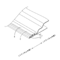
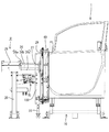
一般に、自動車のドアパネル1は、アウタパネル3とインナパネル4の2枚のパネルから構成されている。図1に示すように、アウタパネル3は、外周端部を一定幅に渡って折り返して、インナパネル4の外周端部を挟み込む構造(へミング結合構造)となっている。そして、両パネル3、4の継目に塗布したシーリング剤Sを乾燥(加熱処理)させることによって、両パネル3、4の継目を防水(シール)している。
Generally, a
下記特許文献1には、ヒータの熱を、ブロアを利用して吹きかけることにより、ドアパネルに塗布したシーリング剤を乾燥させる熱風乾燥方式の装置が開示されている。
熱風乾燥方式の装置は、熱の利用効率が低いので乾燥時間が長くなる傾向になる。自動車の組み立てラインでは、工程ごとに作業時間(サイクルタイム)が設定されている。近年では、作業時間(サイクルタイム)の短縮化を図ることで生産性を高めることが求められており、従来の熱風乾燥方式の装置では、そうした要請に対応することが出来ない状況にあった。
本発明は上記のような事情に基づいて完成されたものであって、シーリング剤の乾燥作業を、サイクルタイム内で完了させることを目的とする。
Since the hot air drying system has low heat utilization efficiency, the drying time tends to be long. In an automobile assembly line, a work time (cycle time) is set for each process. In recent years, it has been demanded to improve productivity by shortening the working time (cycle time), and the conventional hot air drying system cannot meet such demands.
This invention is completed based on the above situations, Comprising: It aims at completing the drying operation of a sealing agent within cycle time.
本発明は、前面壁に挿通溝を形成した炉体の内部にヒータを配置してなる電気炉構造の加熱装置を用いて、ドアパネルの外縁部に塗布したシーリング剤を乾燥(熱硬化)させるシーリング剤の乾燥方法であって、前記加熱装置を、作業台にセットされたドアパネルから離間した待機位置から、ドアパネルの外縁部を前記挿通溝を通じて炉体内に収める加熱位置に移動させる前進ステップと、前記加熱位置に移動した前記加熱装置の前記炉体内にて、ドアパネルの外縁部に塗布されたシーリング剤を、前記ヒータにより加熱する加熱ステップと、前記加熱ステップの終了後、前記加熱装置を前記加熱位置から前記待機位置に後退させる後退ステップとを含み、前記後退ステップの終了後、前記前進ステップを次に実行するまでの間、前記待機位置にある前記加熱装置の前記挿通溝を閉止部材によって閉止することにより、前記炉体内の熱が前記挿通溝から外に逃げるのを抑えるところに特徴を有する。 The present invention relates to a sealing method for drying (thermosetting) a sealing agent applied to an outer edge portion of a door panel by using a heating device having an electric furnace structure in which a heater is disposed inside a furnace body having an insertion groove formed in a front wall. A method of drying an agent, wherein the heating device is moved from a standby position separated from a door panel set on a work bench to a heating position in which an outer edge portion of the door panel is accommodated in the furnace through the insertion groove; and The heating step of heating the sealing agent applied to the outer edge of the door panel by the heater in the furnace of the heating device moved to the heating position, and after the heating step, the heating device is moved to the heating position. Retreating step for retreating from the standby position to the standby position, and after the end of the reverse step, until the next forward step is executed, the standby position By closing the closing member said insertion groove of said heating device in the furnace body heat has characterized in that suppress the escape out of the insertion groove.
本発明は、ドアパネルの外縁部に塗布されたシーリング剤の乾燥工程は、前進ステップと、加熱ステップと、後退ステップとの3ステップを含む工程となっており、前進ステップでは、加熱装置が待機位置から加熱位置に移動し、挿通溝を通じて炉体内にドアパネルの外縁部が収められる。 In the present invention, the drying process of the sealing agent applied to the outer edge portion of the door panel includes a forward step, a heating step, and a backward step. In the forward step, the heating device is in a standby position. To the heating position, and the outer edge of the door panel is stored in the furnace through the insertion groove.
続く加熱ステップでは、ドアパネルの外縁部に塗布されたシーリング剤をヒータが加熱し、シーリング剤は乾燥(熱硬化)する。続く後退ステップでは、加熱装置が加熱位置から待機位置に後退する。これにより、加熱装置はドアパネルから離間するので、炉体に形成された挿通溝は開放状態となる。 In the subsequent heating step, the heater heats the sealing agent applied to the outer edge of the door panel, and the sealing agent is dried (thermosetting). In the subsequent reverse step, the heating device moves backward from the heating position to the standby position. Thereby, since a heating apparatus leaves | separates from a door panel, the insertion groove formed in the furnace body will be in an open state.
そして、後退ステップの終了後、前記前進ステップを次に実行するまでの間、待機位置にある加熱装置の挿通溝を閉止部材が閉止するため、ヒータにより加熱された炉体内の空気が挿通溝から外に逃げるのを防止できる。そのため、ヒータの温度低下を抑えることが出来て、ヒータ温を設定温度(シーリング剤を乾燥させるために必要な設定温度)に保てる。 And since the closing member closes the insertion groove of the heating device at the standby position after the backward step is completed until the forward step is executed next, the air in the furnace heated by the heater is removed from the insertion groove. You can prevent you from escaping outside. Therefore, the temperature drop of the heater can be suppressed, and the heater temperature can be kept at a set temperature (set temperature necessary for drying the sealing agent).
ここで仮に、ヒータ温が設定温度を下回ってしまうと、ヒータ温が設定温度を上回る状態に戻るまで、次のドアパネルに対するシーリング剤の加熱作業を待たなければならず、加熱作業の開始タイミングが遅れる結果、サイクルタイム内に加熱作業を終了させることが困難になる。この点、本発明であれば、挿通溝を閉止してヒータの温度低下を防ぐようにしていることから、加熱作業を予定のタイミングで開始できる。そのため、シーリング剤の加熱作業をサイクルタイム内で完了させること可能となる。 Here, if the heater temperature falls below the set temperature, the heating operation of the sealing agent for the next door panel must be waited until the heater temperature returns to a state above the set temperature, and the start timing of the heating operation is delayed. As a result, it becomes difficult to finish the heating operation within the cycle time. In this regard, according to the present invention, since the insertion groove is closed to prevent the temperature of the heater from decreasing, the heating operation can be started at a scheduled timing. Therefore, the heating operation of the sealing agent can be completed within the cycle time.
この発明の実施形態として、以下の構成とすることが好ましい。
炉体内に設けた仕切り壁によって、炉体内における上昇気流の発生を抑えるようにする。炉体を縦向きにして使用する場合には、内部で上昇気流が発生して温度分布が不均一になる恐れがあるが、上記構成にしておけば、仕切り壁が上昇気流の発生を抑えるので、炉体内の温度分布を均一にすることが可能となる。
As an embodiment of the present invention, the following configuration is preferable.
Generation of upward airflow in the furnace body is suppressed by a partition wall provided in the furnace body. When the furnace body is used in a vertical orientation, an updraft may be generated inside and the temperature distribution may be non-uniform, but if the above configuration is used, the partition wall will suppress the updraft. It becomes possible to make the temperature distribution in the furnace uniform.
本発明によれば、シーリング剤の加熱作業をサイクルタイム内にて完了させることを目的とする。 An object of the present invention is to complete the heating operation of the sealing agent within the cycle time.
本発明の一実施形態を図1ないし図17によって説明する。
1.全体説明
ドアパネル1は鋼板製のアウタパネル3と、同じく鋼板製のインナパネル4の2枚のパネルから構成されている。図1に示すように、アウタパネル3は外周端部を一定幅に渡って折り返して、インナパネル4の外周端部を挟み込む構造(へミング結合構造)となっている。
An embodiment of the present invention will be described with reference to FIGS.
1. General Description The
ドアパネル1の継目(へミング結合された両パネル3,4の境目)は防水処理する必要があり、熱硬化性のシーリング剤(例えばポリ塩化ビニルを主成分とした高粘度の高分子材料)Sを塗布している。以下、ドアパネル1のうち、フロント側の外縁部7の継目に塗布されたシーリング剤Sを加熱処理する加熱設備Uの構成を説明する。
The joint of the door panel 1 (the boundary between the hemming-bonded
2.加熱設備Uの説明
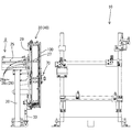
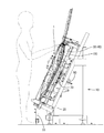
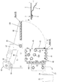
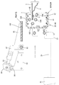
加熱設備Uは、支柱20と、エアシリンダ装置25と、加熱装置30と、開閉ユニット70とを主体に構成されている。支柱20は例えば、角筒型の金属パイプから構成されたものであって、作業台10の側方(図2、図3では左側)に立てた状態で配置されている。作業台10はアングルをH型に組んだものであり、ドアパネル1をやや後傾させつつ概ね立てた姿勢で安定的に支持できる構造となっている。
2. Description of Heating Equipment U The heating equipment U is mainly composed of a
支柱20の上部にはエアシリンダ装置(本発明の「第一駆動装置」に相当)25が取り付けられている。エアシリンダ装置25は、ロッド軸26を作業台10側に向けた状態で固定されている。エアシリンダ装置25のロッド軸26は、平行な3軸26a〜26cの構成になっていて、軸先端にはブラケット27が取り付けられている。ブラケット27には、連結パイプ29を介して加熱装置30が取り付けられている。
An air cylinder device (corresponding to the “first drive device” of the present invention) 25 is attached to the upper portion of the
尚、この実施形態では、作業台10上に、ドアパネル1を縦向きにセットして、シーリング剤Sの加熱作業を行うことから、加熱装置30についても、ドアパネル1の向きに倣ってロッド軸26に対して縦向きに取り付けられている。
In this embodiment, since the
エアシリンダ装置25はロッド軸26の伸長・収縮により、加熱装置30を図3に示す待機位置(ドアパネル1から離間する位置)と、図5に示す加熱位置(ドアパネル1の外縁部7を、挿通溝45を通じて炉体40内に収める位置)とに変位させる機能を担うものである。尚、以下の説明において、上下方向とは使用時の向きを意味するものとし、また前後方向は、ドアパネル1に向かい合う側を前側、その反対側を後側とする。
The
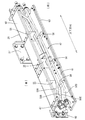
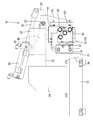
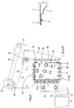
加熱装置30は下部に設けたキャスター33を設けており、移動自在な構成となっている。加熱装置30はいわゆる電気炉構造であり、炉体40の内部に遠赤外線ヒータ50(50A〜50Dの総称)を収容した構成となっている。具体的に説明すると、図7、図14に示すように、炉体40は金属フレーム41と、断熱材60とから構成されている。金属フレーム41は、例えばステンレス製の板材からなり、上下方向に長い概ね角筒型(中空筒型)をなす。尚、図7は加熱装置の斜視図(遠赤外線ヒータ50が納められた炉体40の斜視図)である。また、図14は加熱装置30及び開閉ユニット70の動作説明図(初期状態を示す断面図である)。
The
そして、金属フレーム41の前面壁(ドアパネル1に相対する側の壁)43には、挿通溝45が開口している。挿通溝45は、前面壁43の全長に渡って形成されている。挿通溝45はドアパネル1のフロント側の外縁部7(図3参照)を、炉室(炉体40の内部空間)42へ挿通させるものである。挿通溝45の形状は、ドアパネル1のフロント側の外縁部7の形状が、緩やかに湾曲した形状であることに対応して、緩やかに折れ曲った形状となっている。
An
この実施形態では、金属フレーム41のうち前面壁43は分割構造になっていて、金属フレーム41に螺子で固定する構造としてあるが、前面壁43を含む金属フレーム41を一枚の板材から成形してもよい。尚、この実施形態では、図7に示すように、前面壁43の端部にフランジ44を形成して、金属フレーム41の端面部分に出来る隙間を閉止するようにしている。このような構成にすることで、炉体40の密閉性を高めることが可能となることから、遠赤外線ヒータ50の熱が逃げ難くなる。
In this embodiment, the
断熱材60は無機質ファイバーで補強したガラス粉末を、平板状に成形したものであり、金属フレーム41の外周壁(ただし、前面壁43を除く)に重ねるようにして取り付けられている。断熱材60は金属フレーム41の外周壁を全高に渡って覆う大きさとなっている。
The
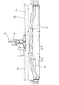
図8、図14に示すように、炉室42内には4本の遠赤外線ヒータ50A〜50Dが取り付けられている。遠赤外線ヒータ50A〜50Dは、充填材を充填した金属パイプの外周面に高効率遠赤輻射塗料を塗布したものであり、金属パイプの内部に収容したニクロム抵抗線を通電すると、発熱に伴って遠赤外線が放射される構成となっている。
As shown in FIGS. 8 and 14, four far-
各遠赤外線ヒータ50A〜50Dはいずれも上下方向に長い形状をしており、金属フレーム41の上下両端に取り付けられた金属製のブラケット47に、長手方向の両端部(ヒータの両端部)を固定している。各遠赤外線ヒータ50A〜50Dの形状は挿通溝45(図7参照)と同じく、ドアパネル1の形状が緩やかに湾曲した形状であることに対応して緩やかに折れ曲った形状となっている。尚、金属製のブラケット47は前面壁43側のフランジ44と共に金属フレーム41の端面を閉止する機能を果たしている。
Each of the far
そして、この実施形態では、図16に示すように4本の遠赤外線ヒータ50A〜50Dを、炉室42に収容されたドアパネル1のフロント側の外縁部7を取り囲むように配置しており、4本の遠赤外線ヒータ50A〜50Bにより、ドアパネル1のフロント側の外縁部7の全体を加熱する構成となっている。
In this embodiment, as shown in FIG. 16, four far
尚、4本の遠赤外線ヒータ50A〜50Dのうち、50Aと50Bの両ヒータは、ドアパネル1のうちインナパネル4側にあって、シーリング剤Sを直接加熱する構成となっている。また、50Cと50Dの両ヒータは、ドアパネル先端の正面とアウタパネル3側にそれぞれ配置されている。また、各遠赤外線ヒータ50A〜50Dには、それぞれ温度センサ(例えば、熱電対)が装着されていて、遠赤外線ヒータ50の表面温度を検出する構成になっている。
Of the four far-
図8に戻って説明を続けると、炉室42内には、仕切り壁55が取り付けられている。仕切り壁55は、例えばステンレス製の板材であって、炉室42を上下方向に仕切る役目を果たしている。この例では、炉体40に対して平板状の仕切り壁を一定の間隔で3枚取り付けていて、炉室(炉体40の内部空間)42を4室に画す構成となっている。尚、仕切り壁55の中央部には受け入れ溝56が形成されており、4本のヒータ50A〜50Dと共に、ドアパネル1のフロント側の外縁部7を前方から受け入れる構成となっている。
Returning to FIG. 8 and continuing the description, a
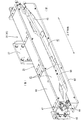
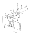
続いて、炉体40に形成された挿通溝45(図7参照)を開閉する開閉ユニット70の説明を図9、図10を参照して行う。開閉ユニット70はベースプレート80と、回転リンク85と、エアシリンダ装置(本発明の「第二駆動装置」に相当)90と、閉止板(本発明の「閉止部材」に相当)100とから構成されている。
Next, the opening /
ベースプレート80は概ね三角形状をしており、取り付けプレート23、24を介して支柱20に固定されている。このベースプレート80には、回転リンク85を介して閉止板100が取り付けられている。回転リンク85はベースプレート80の先端部に設けられたヒンジ83に軸止されていて、ヒンジ83を軸に回転可能となっている。
The
閉止板100は例えばステンレス製の板材からなり、炉体40の前面壁43の全体を覆う大きさとされる。また、閉止板100の裏面側(前面壁43に相対する側を表面とする)には断熱材110が取り付けられている。断熱材110は断熱材60(図8参照)と同じく、無機質ファイバーで補強したガラス粉末を平板状に成形したものである。断熱材110は、閉止板100のうち、回転リンク85が固定される中央部を除いた両側に取り付けられている。
The
また、エアシリンダ装置90は、ベースプレート80に対してヒンジ84を介して取り付けられている。そして、エアシリンダ装置90のロッド軸93の先端が、回転リンク85に固定された連結部材87に軸止されている。
The
以上のことから、エアシリンダ装置90のロッド軸93を伸長・収縮させることにより、ヒンジ83を中心に閉止板100を回転させることが可能であり、閉止板100を図10に示す閉止位置と、図11に示す開放位置に変位操作できる構成となっている。
From the above, it is possible to rotate the
図10に示す閉止位置では、待機位置に停止した炉体40の前面壁43に閉止板100が重なった状態となり、前面壁43に形成された挿通溝45は閉止板100により閉止される。また、図11に示す開放位置では、閉止板100が炉体40の前方を開放することから、待機位置にある炉体40は前方への移動、すなわち加熱位置への移動が可能になる。
10, the
尚、図中省略してあるが加熱設備Uには制御装置が設けられている。制御装置はソレノイドバルブを通電制御することにより各エアシリンダ装置25、90を個々に制御する機能と、温度センサの出力をフィードバックして各ヒータ50A〜50Dを通電制御することに各遠赤外線ヒータ50A〜50Dの表面温度を設定温度(一例として約600℃)に保つ機能を担っている。
Although not shown in the figure, the heating equipment U is provided with a control device. The control device controls each
3.乾燥工程の説明
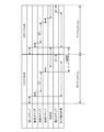
次に、シーリング剤Sの乾燥工程について説明を行う。乾燥工程は、搬入ステップと、前進ステップと、加熱ステップと、後退ステップと、搬出ステップの5つのステップから構成されている(図13参照)。尚、ここでは、ドアパネル1のうち、フロント側の外縁部7に塗布されたシーリング剤Sを乾燥させるものとする。
3. Next, the drying process of the sealing agent S will be described. The drying process is composed of five steps: a carry-in step, a forward step, a heating step, a reverse step, and a carry-out step (see FIG. 13). Here, the sealing agent S applied to the outer edge 7 on the front side of the
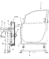
また、作業開始にあたり、図2、図14に示すように、加熱装置30は待機位置にあるものとし、閉止板100は閉止位置にあって炉体40の前面壁43の挿通溝45を閉止した状態にあるものとする。そして、加熱装置30の各遠赤外線ヒータ50はいずれも通電状態にあって、ヒータ温は設定温度になっているものとする。尚、以下に説明する乾燥工程中、遠赤外線ヒータ50は、制御装置により、ヒータ温が設定温度になるようにフィードバック制御されている。
Further, at the start of the work, as shown in FIGS. 2 and 14, it is assumed that the
搬入ステップでは、図3に示すようにシーリング剤Sの塗布工程を終えたドアパネル1が、作業台10に対して運びこまれる。ドアパネル1の搬入は作業者により行われる。
In the carry-in step, the
そして、ドアパネル1の搬入を完了させた作業者により、加熱設備Uの周辺に設置された起動釦(図略)が押されると、制御装置が、エアシリンダ装置90を作動させる。これにより、エアシリンダ装置90のロッド軸93が収縮することから、閉止位置にある閉止板100は開き方向(図15のR方向)に回転してゆく。そして、閉止板100が閉止位置から約90度回転して、図15に示す開放位置に至ると、そこで、制御装置はエアシリンダ装置90の作動を停止させる。これにて、閉止板100は図15に示す開放位置に停止し、加熱装置30の前方は開放された状態となる。
When a start button (not shown) installed around the heating facility U is pressed by an operator who has completed the loading of the
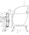
制御装置は、エアシリンダ装置90の作動を停止させると、次に、エアシリンダ装置25を作動させる。これにより、今度はエアシリンダ装置25のロッド軸26が伸長して、待機位置にある加熱装置30をドアパネル1に向かって前進させる。これにより、加熱装置30はドアパネル1の外縁部7に接近してゆき、やがて、ドアパネル1の外縁部7が挿通溝45を通じて炉体40の炉室42に差し込まれてゆく。
When the operation of the
そして、加熱装置30が、図5、図16に示す加熱位置に至ると、そこで、制御装置はエアシリンダ装置25の作動を停止させる。これにて、加熱装置30は加熱位置にて停止する。この加熱位置では、炉体40に挿入されたドアパネル1のフロント側の外縁部7の周囲を、4つの遠赤外線ヒータ50A〜50Dが囲んだ状態となる(前進ステップ)。
When the
その後、制御装置は、加熱装置30を加熱位置に一定時間t1停止させる。これにより、ドアパネル1のフロント側の外縁部7は、炉体40内に一定時間t1差し込まれた状態となり、ドアパネル1のフロント側の外縁部7に塗布されたシーリング剤Sは、遠赤外線ヒータ50A〜50Dから放射される遠赤外線により加熱される。これにより、シーリング剤Sは熱硬化し、乾燥する(加熱ステップ)。
Thereafter, the control device stops the
そして、加熱位置への移動後一定時間t1が経過すると、制御装置は、再びエアシリンダ装置25を作動させてロッド軸26を収縮させることにより、加熱位置にある加熱装置30を後退させる。これにより、加熱装置30はドアパネル1から離間してゆく。そして、加熱装置30が図4、図17に示す待機位置に後退すると、そこで、制御装置は、エアシリンダ装置25の作動を停止させる。これにより、加熱装置30は待機位置に停止した状態となる(後退ステップ)。
Then, when a certain time t1 has elapsed after the movement to the heating position, the control device operates the
制御装置は、エアシリンダ装置25の作動を停止させると、次に、エアシリンダ装置90を作動させて、ロッド軸93を伸長させる。これにより、開放位置にある閉止板100は閉じ方向(図15中のQ方向)に回転してゆく。そして、閉止板100が図14に示す閉止位置に至ると、そこで、制御装置はエアシリンダ装置90の作動を停止させる。これにて、閉止板100は図14に示す閉止位置に停止する。
When the operation of the
閉止位置では、閉止板100が炉体40の前面壁43の前方に位置して挿通溝45を閉じることから、ヒータ50により加熱された炉室42内の空気が挿通溝45を通じて外に逃げ難くなる。そのため、炉室42内の温度が下がり難くなることから、各遠赤外線ヒータ50A〜50Dの表面温度を設定温度に保つことが可能となる(熱保持)。尚、閉止板100は、次に前進ステップが実行されるまで閉止位置に留まるので、図13に示すように、次のサイクルで再び、前進ステップが実行される時まで熱保持の状態が続くことになる。
In the closed position, the
一方、作業者は、ドアパネル1の搬入後、別工程で別作業を行っており、そこでの作業が完了すると、シーリング剤Sの加熱処理を完了させたドアパネル1を作動台10から運びだして、次工程の作業台に搬出する(搬出ステップ)。これにて、1枚目のドアパネル1に対する乾燥工程は終了し、乾燥工程の作業台10は再び空いた状態となる。
On the other hand, after carrying in the
そして、1枚目のドアパネル1に対する乾燥工程が終了すると、次に2枚目のドアパネル1に対する乾燥工程が、1枚目のドアパネル1と同様の手順で行われる。
When the drying process for the
すなわち、まず、搬入ステップでシーリング剤Sの塗布工程を終えたドアパネル1が作業台10に運びこまれる。その後、前進ステップで、まず、エアシリンダ90が閉止板100を閉止位置から開放位置に移動させる。これにより、閉止板100による熱保持が一旦解かれる。そして、閉止板100が開放位置に移動すると、今度は、エアシリンダ装置25が加熱装置30を待機位置から加熱位置に移動させる。
That is, first, the
続く加熱ステップでは、加熱装置30の炉体42内にて加熱されて、ドアパネル1の外縁部7に塗布されたシーリング剤Sは乾燥する。その後、後退ステップでは、エアシリンダ装置25が加熱装置30を加熱位置に待機位置に後退させる。そして、後退ステップの終了後には、待機位置に後退した加熱装置30の挿通溝45を閉止板100が閉止して、ヒータ温を設定温度に保つ。そして、搬出ステップでは、乾燥工程を終えたドアパネル1が作動台10から次工程の作業台へ搬出される。これにて、2枚目のドアパネル1に対する乾燥工程は終了し、作業台10は再び空いた状態となる。
In the subsequent heating step, the sealing agent S heated in the
このように本実施形態では、搬入ステップと、前進ステップと、加熱ステップと、後退ステップと、搬出ステップの5つのステップを1サイクルとしてシーリング剤Sの乾燥工程が行われ、後退ステップの終了後、前進ステップを次に実行するまでの間は、加熱装置30の挿通溝45を閉止板100によって閉止することにより、炉体40内の熱が挿通溝45から外に逃げるのを防止する。
As described above, in this embodiment, the drying process of the sealing agent S is performed with the five steps of the carry-in step, the forward step, the heating step, the reverse step, and the carry-out step as one cycle, and after the end of the reverse step, Until the next forward step is executed, the
4.効果説明
本実施形態では、加熱装置30を電気炉構造(遠赤外線ヒータ50を炉体40で囲んで熱を閉じ込める構造)とした。電気炉構造であれば、従来の熱風乾燥方式の装置に比して熱の利用効率が高い。しかも、本実施形態では、遠赤外線ヒータ50を使用していることから、シーリング剤Sに熱が伝わり易い。そのため、シーリング剤Sを短時間の加熱で乾燥させることが可能であり、また消費電力を抑えることが可能となる。
4). Description of Effects In this embodiment, the
また、乾燥工程を、図13に示すサイクルタイムT内で終了させるには、加熱ステップから次の加熱ステップまでの間(図13中のA期間)に、遠赤外線ヒータ50A〜50Dの表面温度が設定温度を下回らないように、ヒータ温を維持する必要がある。これは、ヒータ温が設定温度を下回ると、ヒータ温が設定温度を上回る状態に回復するまで、ドアパネル1に対する加熱作業を待たなければならず、加熱作業の開始が遅れる。そのため、サイクルタイムT内で加熱作業を完了させることが出来なくなるからである。
Further, in order to finish the drying process within the cycle time T shown in FIG. 13, the surface temperature of the far-
この点、本実施形態では、炉体40の挿通溝45を閉止することでヒータ温の低下を防ぐようにしていることから、加熱ステップから次に加熱ステップを行うまでの間、ヒータ温を設定温度に保つことが可能となり、加熱作業を予定のタイミングで開始できる。そのため、シーリング剤Sの加熱作業をサイクルタイムT内で完了させること可能となる。
In this respect, in the present embodiment, the heater groove is prevented from being lowered by closing the
また、挿通溝45を閉止することで、加熱装置周囲の温度上昇を抑えることが可能となり、作業者に対して良好な作業環境を提供できる。
Moreover, by closing the
また、加熱装置30は縦向きで使用されるため、炉室42内に上昇気流(熱の対流)が起きやすく、炉室42の温度が不均一になったり、暖められた熱が加熱装置30の上面側から外に逃げ易くなる。この点、本加熱装置30は、仕切り壁55によって炉室42を仕切るようにしているから、上昇気流が発生し難くなる。そのため、炉室42の温度分布を均一にすることが可能となり、シーリング剤Sをその全高に渡って均一に加熱することが可能となる。また、ヒータ50A〜50Dの熱が逃げ難くなり、熱の利用効率が一層高まる。
In addition, since the
<他の実施形態>
本発明は上記記述及び図面によって説明した実施形態に限定されるものではなく、例えば次のような実施形態も本発明の技術的範囲に含まれる。
<Other embodiments>
The present invention is not limited to the embodiments described with reference to the above description and drawings. For example, the following embodiments are also included in the technical scope of the present invention.
(1)上記実施形態では、炉体40に形成された挿通溝45を閉止する閉止部材の一例に閉止板100を挙げた。閉止部材は、挿通溝45を閉止するものであればよく、閉止板100に限定されない。例えば、挿通溝45の閉止用にドアパネルの形状を模したパネル(ダミーのドアパネル)を1枚用意し、そのパネルを挿通溝45に差し込むことによって、挿通溝45を閉止してもよい。
(1) In the above embodiment, the
(2)また、開閉板100は加熱装置30の前面壁43にヒンジを介して直接取り付ける構造にすることが可能である。
(2) The opening /
(3)上記実施形態では、加熱装置30の一例として、炉体40の内部に4本の遠赤外線ヒータ50A〜50Dを収容したものを例示した。遠赤外線ヒータ50の使用本数は、4本に限定されるものではなく、例えば、サイクルタイムTの長さや、ドアパネルの板厚、形状により、使用本数を決定することが好ましい。また、ヒータは、遠赤外線ヒータである必要は必ずしもなく、電気式のヒータ(通電により抵抗発熱体を発熱させるもの)であれば適用可能である。
(3) In the said embodiment, what accommodated the four far-
(4)上記実施形態では、ドアパネル1を縦向きにしてシーリング剤Sの乾燥作業を行う(すなわち、乾燥作業時、シーリング剤Sの塗布ラインが縦向きであった)ことから、遠赤外線ヒータ50を縦方向(上下方向)に長い形状とした。遠赤外線ヒータ50の形状は、シーリング剤Sの塗布ラインと同方向にする必要はなく、塗布ラインに対して直交する方向、すなわち、実施形態1の構成であれば横方向(水平方向)に長い形状としてもよい。
(4) In the above embodiment, the drying operation of the sealing agent S is performed with the
(5)上記実施形態では、作業台10に対するドアパネル1の搬入作業、搬出作業を作業者に行わせる例を挙げたが、これら搬入・搬出作業は、作業者に替えて、搬送ロボットに行わせるようにしてもよい。また、搬入作業、搬出作業を搬送ロボットに行う場合、搬入作業終了から搬出作業を行うまでの間は、搬送ロボットに別工程で別作業を行わせるとよい。
(5) In the above-described embodiment, an example is given in which the worker carries out the carry-in work and the carry-out work of the
(6)上記実施形態では、ドアパネル1のうち、フロント側の外縁部7に塗布したシーリング剤Sを乾燥させる場合を、例にして加熱設備Uや乾燥工程の説明を行った。本発明は、ドアパネル1の外縁部に塗布したシーリング剤Sを乾燥作業に広く適用することが可能であり、例えば、フロント側を含むドアパネルの全周(外縁部の全周)に塗布されたシーリング剤の乾燥に適用できる。
(6) In the said embodiment, the case where the sealing agent S apply | coated to the outer edge part 7 of the front side among the
1…ドアパネル
3…アウタパネル
4…インナパネル
7…外縁部
25…エアシリンダ装置(本発明の「第一駆動装置」に相当)
30…加熱装置
40…炉体
43…前面壁
45…挿通溝
55…仕切り壁
50A〜50D…遠赤外線ヒータ
70…開閉ユニット
90…エアシリンダ装置(本発明の「第二駆動装置」に相当)
100…閉止板(本発明の「閉止部材」に相当)
S…シーリング剤
U…加熱設備
DESCRIPTION OF
DESCRIPTION OF
100 ... Closing plate (corresponding to "closing member" of the present invention)
S ... Sealing agent U ... Heating equipment
Claims (4)
前記加熱装置を、作業台にセットされたドアパネルから離間した待機位置から、ドアパネルの外縁部を前記挿通溝を通じて炉体内に収める加熱位置に移動させる前進ステップと、
前記加熱位置に移動した前記加熱装置の前記炉体内にて、ドアパネルの外縁部に塗布されたシーリング剤を、前記ヒータにより加熱する加熱ステップと、
前記加熱ステップの終了後、前記加熱装置を前記加熱位置から前記待機位置に後退させる後退ステップとを含み、
前記後退ステップの終了後、前記前進ステップを次に実行するまでの間、前記待機位置にある前記加熱装置の前記挿通溝を閉止部材によって閉止することにより、前記炉体内の熱が前記挿通溝から外に逃げるのを抑えることを特徴とするシーリング剤の乾燥方法。 A method for drying a sealing agent, wherein a sealing agent applied to an outer edge of a door panel is dried using a heating device having an electric furnace structure in which a heater is disposed inside a furnace body in which an insertion groove is formed in a front wall,
A forward step of moving the heating device from a standby position spaced from a door panel set on a workbench to a heating position in which the outer edge of the door panel is housed in the furnace through the insertion groove;
In the furnace of the heating device moved to the heating position, a heating step of heating the sealing agent applied to the outer edge portion of the door panel by the heater,
A retreating step of retracting the heating device from the heating position to the standby position after completion of the heating step;
By closing the insertion groove of the heating device at the standby position by a closing member until the next forward step is executed after the backward step is completed, the heat in the furnace body is transferred from the insertion groove. A method of drying a sealing agent characterized by suppressing escape to the outside.
前記ドアパネルの外縁部を挿通させる挿通溝を前面壁に形成した中空筒状の炉体内にヒータを配置してなる加熱装置と、
前記加熱装置を、作業位置にセットされたドアパネルから離間した待機位置と、ドアパネルの外縁部を前記挿通溝を通じて炉体内に収める加熱位置とに変位させる第一駆動装置と、
前記挿通溝を閉止可能な閉止部材と、
前記閉止部材を、前記挿通溝を開放する開放位置と前記挿通溝を閉止する閉止位置とに変位させる第二駆動装置とを備えたことを特徴とする加熱設備。 A heating facility that dries by heating the sealing agent applied to the outer edge of the door panel,
A heating device in which a heater is disposed in a hollow cylindrical furnace body in which an insertion groove for inserting an outer edge portion of the door panel is formed on the front wall;
A first driving device for displacing the heating device to a standby position separated from a door panel set at a working position and a heating position in which an outer edge portion of the door panel is housed in the furnace through the insertion groove;
A closing member capable of closing the insertion groove;
A heating facility comprising: a second drive device that displaces the closing member to an open position for opening the insertion groove and a closing position for closing the insertion groove.
Priority Applications (1)
| Application Number | Priority Date | Filing Date | Title |
|---|---|---|---|
| JP2011045241A JP5659047B2 (en) | 2011-03-02 | 2011-03-02 | Sealing agent drying method and heating equipment |
Applications Claiming Priority (1)
| Application Number | Priority Date | Filing Date | Title |
|---|---|---|---|
| JP2011045241A JP5659047B2 (en) | 2011-03-02 | 2011-03-02 | Sealing agent drying method and heating equipment |
Publications (2)
| Publication Number | Publication Date |
|---|---|
| JP2012180995A JP2012180995A (en) | 2012-09-20 |
| JP5659047B2 true JP5659047B2 (en) | 2015-01-28 |
Family
ID=47012337
Family Applications (1)
| Application Number | Title | Priority Date | Filing Date |
|---|---|---|---|
| JP2011045241A Active JP5659047B2 (en) | 2011-03-02 | 2011-03-02 | Sealing agent drying method and heating equipment |
Country Status (1)
| Country | Link |
|---|---|
| JP (1) | JP5659047B2 (en) |
Cited By (1)
| Publication number | Priority date | Publication date | Assignee | Title |
|---|---|---|---|---|
| CN104677073A (en) * | 2015-03-23 | 2015-06-03 | 浙江华立涂装设备有限公司 | Electrophoresis drying stove structure |
Families Citing this family (2)
| Publication number | Priority date | Publication date | Assignee | Title |
|---|---|---|---|---|
| JP5579521B2 (en) * | 2010-07-22 | 2014-08-27 | 中部電力株式会社 | Method of thermosetting polymer material and electric heating furnace type thermosetting apparatus |
| CN104567341B (en) * | 2014-11-25 | 2016-08-24 | 济南麦哈勃冶金技术开发有限公司 | Large-sized drying machines coaming plate |
Family Cites Families (8)
| Publication number | Priority date | Publication date | Assignee | Title |
|---|---|---|---|---|
| JPS63126579A (en) * | 1986-11-18 | 1988-05-30 | Sunstar Giken Kk | Curing method for sealing material |
| JPH0614826Y2 (en) * | 1987-09-28 | 1994-04-20 | トリニティ工業株式会社 | Infrared heating furnace |
| JPH05325682A (en) * | 1992-05-14 | 1993-12-10 | Hitachi Cable Ltd | Taping / heat treatment device for linear objects |
| JPH10193080A (en) * | 1997-01-06 | 1998-07-28 | Fuji Electric Co Ltd | Crucible-shaped automatic pouring furnace |
| JP3596585B2 (en) * | 1997-12-25 | 2004-12-02 | 三菱自動車工業株式会社 | Precure equipment for sheet metal work |
| JP2008249215A (en) * | 2007-03-29 | 2008-10-16 | Nec Corp | Vertical type heating furnace |
| JP5320315B2 (en) * | 2010-01-22 | 2013-10-23 | 中部電力株式会社 | Method of thermosetting polymer material and thermosetting device |
| JP5579521B2 (en) * | 2010-07-22 | 2014-08-27 | 中部電力株式会社 | Method of thermosetting polymer material and electric heating furnace type thermosetting apparatus |
-
2011
- 2011-03-02 JP JP2011045241A patent/JP5659047B2/en active Active
Cited By (1)
| Publication number | Priority date | Publication date | Assignee | Title |
|---|---|---|---|---|
| CN104677073A (en) * | 2015-03-23 | 2015-06-03 | 浙江华立涂装设备有限公司 | Electrophoresis drying stove structure |
Also Published As
| Publication number | Publication date |
|---|---|
| JP2012180995A (en) | 2012-09-20 |
Similar Documents
| Publication | Publication Date | Title |
|---|---|---|
| JP5568377B2 (en) | Drying method | |
| JP5659047B2 (en) | Sealing agent drying method and heating equipment | |
| WO2008020812A1 (en) | System for improved powder coating of duct fittings and process for same | |
| WO2017081812A1 (en) | Three-dimensional additive manufacturing device, production method for three-dimensional additive manufacturing device, and production program for three-dimensional additive manufacturing device | |
| US20130167488A1 (en) | Hot wind supplying apparatus for packaging product | |
| JP6034489B2 (en) | Extrusion die preheating apparatus and method | |
| CN202359158U (en) | Heating furnace | |
| US20030163932A1 (en) | Process for forming a coating film on vehicle body, and sealing-agent drying apparatus | |
| JP5760907B2 (en) | Heating apparatus and heating method | |
| CN216977387U (en) | Infrared catalyst auxiliary heating device | |
| KR101442029B1 (en) | Apparatus for manufacturing vacuum pair glass | |
| JP2005535483A5 (en) | ||
| CN203881054U (en) | Eight-door cylindrical vacuum oven | |
| CN109968664A (en) | Three-dimension object manufacturing equipment, preheating device and cylinder body heating mechanism | |
| KR20150055867A (en) | Furnace for manufacturing curved glass | |
| CN206278345U (en) | Heat-shrink tube heat-sealing oven body and glass tube heat shrink wrapping machine | |
| JP5579521B2 (en) | Method of thermosetting polymer material and electric heating furnace type thermosetting apparatus | |
| JP5320315B2 (en) | Method of thermosetting polymer material and thermosetting device | |
| JP6759299B2 (en) | Mold manufacturing method and manufacturing equipment | |
| CN209037989U (en) | A kind of outer packaging machine of cigarette production | |
| CN208567371U (en) | A kind of automatic drying device of multiple rows of storage | |
| CN120299844B (en) | Intelligent packaging equipment and packaging process of piezoresistor and piezoresistor | |
| JP6379842B2 (en) | Dyeing equipment | |
| CN206052081U (en) | Air ducting in horizontal bright annealing furnace flue | |
| JPH0614826Y2 (en) | Infrared heating furnace |
Legal Events
| Date | Code | Title | Description |
|---|---|---|---|
| A621 | Written request for application examination |
Free format text: JAPANESE INTERMEDIATE CODE: A621 Effective date: 20140219 |
|
| A977 | Report on retrieval |
Free format text: JAPANESE INTERMEDIATE CODE: A971007 Effective date: 20141114 |
|
| TRDD | Decision of grant or rejection written | ||
| A01 | Written decision to grant a patent or to grant a registration (utility model) |
Free format text: JAPANESE INTERMEDIATE CODE: A01 Effective date: 20141118 |
|
| A61 | First payment of annual fees (during grant procedure) |
Free format text: JAPANESE INTERMEDIATE CODE: A61 Effective date: 20141201 |
|
| R150 | Certificate of patent or registration of utility model |
Ref document number: 5659047 Country of ref document: JP Free format text: JAPANESE INTERMEDIATE CODE: R150 |
|
| R250 | Receipt of annual fees |
Free format text: JAPANESE INTERMEDIATE CODE: R250 |
|
| R250 | Receipt of annual fees |
Free format text: JAPANESE INTERMEDIATE CODE: R250 |
|
| R250 | Receipt of annual fees |
Free format text: JAPANESE INTERMEDIATE CODE: R250 |
|
| R250 | Receipt of annual fees |
Free format text: JAPANESE INTERMEDIATE CODE: R250 |
|
| R250 | Receipt of annual fees |
Free format text: JAPANESE INTERMEDIATE CODE: R250 |
|
| R250 | Receipt of annual fees |
Free format text: JAPANESE INTERMEDIATE CODE: R250 |
|
| R250 | Receipt of annual fees |
Free format text: JAPANESE INTERMEDIATE CODE: R250 |
|
| R250 | Receipt of annual fees |
Free format text: JAPANESE INTERMEDIATE CODE: R250 |
|
| R250 | Receipt of annual fees |
Free format text: JAPANESE INTERMEDIATE CODE: R250 |