JP5658512B2 - Method for manufacturing magnetic tape on which servo signal is written and servo writer - Google Patents
Method for manufacturing magnetic tape on which servo signal is written and servo writer Download PDFInfo
- Publication number
- JP5658512B2 JP5658512B2 JP2010194447A JP2010194447A JP5658512B2 JP 5658512 B2 JP5658512 B2 JP 5658512B2 JP 2010194447 A JP2010194447 A JP 2010194447A JP 2010194447 A JP2010194447 A JP 2010194447A JP 5658512 B2 JP5658512 B2 JP 5658512B2
- Authority
- JP
- Japan
- Prior art keywords
- magnetic tape
- magnetic
- servo
- signal
- horizontal
- Prior art date
- Legal status (The legal status is an assumption and is not a legal conclusion. Google has not performed a legal analysis and makes no representation as to the accuracy of the status listed.)
- Active
Links
- 238000000034 method Methods 0.000 title claims description 45
- 238000004519 manufacturing process Methods 0.000 title claims description 26
- 230000005347 demagnetization Effects 0.000 claims description 61
- 239000000696 magnetic material Substances 0.000 claims description 38
- 238000011144 upstream manufacturing Methods 0.000 claims description 12
- 230000000052 comparative effect Effects 0.000 description 13
- 230000005415 magnetization Effects 0.000 description 10
- 239000010408 film Substances 0.000 description 6
- 230000004907 flux Effects 0.000 description 6
- 230000000694 effects Effects 0.000 description 4
- 230000032258 transport Effects 0.000 description 4
- 238000004804 winding Methods 0.000 description 4
- 239000011230 binding agent Substances 0.000 description 2
- 238000012790 confirmation Methods 0.000 description 2
- AJCDFVKYMIUXCR-UHFFFAOYSA-N oxobarium;oxo(oxoferriooxy)iron Chemical compound [Ba]=O.O=[Fe]O[Fe]=O.O=[Fe]O[Fe]=O.O=[Fe]O[Fe]=O.O=[Fe]O[Fe]=O.O=[Fe]O[Fe]=O.O=[Fe]O[Fe]=O AJCDFVKYMIUXCR-UHFFFAOYSA-N 0.000 description 2
- 239000003973 paint Substances 0.000 description 2
- 229920000139 polyethylene terephthalate Polymers 0.000 description 2
- 239000005020 polyethylene terephthalate Substances 0.000 description 2
- 229910000859 α-Fe Inorganic materials 0.000 description 2
- 239000006229 carbon black Substances 0.000 description 1
- 239000003795 chemical substances by application Substances 0.000 description 1
- 238000010586 diagram Methods 0.000 description 1
- 238000001035 drying Methods 0.000 description 1
- 239000000314 lubricant Substances 0.000 description 1
- 239000006247 magnetic powder Substances 0.000 description 1
- 230000005389 magnetism Effects 0.000 description 1
- 238000005498 polishing Methods 0.000 description 1
- -1 polyethylene terephthalate Polymers 0.000 description 1
- 229910052712 strontium Inorganic materials 0.000 description 1
- CIOAGBVUUVVLOB-UHFFFAOYSA-N strontium atom Chemical compound [Sr] CIOAGBVUUVVLOB-UHFFFAOYSA-N 0.000 description 1
- 239000000126 substance Substances 0.000 description 1
- 239000010409 thin film Substances 0.000 description 1
Images


Classifications
-
- G—PHYSICS
- G11—INFORMATION STORAGE
- G11B—INFORMATION STORAGE BASED ON RELATIVE MOVEMENT BETWEEN RECORD CARRIER AND TRANSDUCER
- G11B5/00—Recording by magnetisation or demagnetisation of a record carrier; Reproducing by magnetic means; Record carriers therefor
- G11B5/48—Disposition or mounting of heads or head supports relative to record carriers ; arrangements of heads, e.g. for scanning the record carrier to increase the relative speed
- G11B5/58—Disposition or mounting of heads or head supports relative to record carriers ; arrangements of heads, e.g. for scanning the record carrier to increase the relative speed with provision for moving the head for the purpose of maintaining alignment of the head relative to the record carrier during transducing operation, e.g. to compensate for surface irregularities of the latter or for track following
- G11B5/584—Disposition or mounting of heads or head supports relative to record carriers ; arrangements of heads, e.g. for scanning the record carrier to increase the relative speed with provision for moving the head for the purpose of maintaining alignment of the head relative to the record carrier during transducing operation, e.g. to compensate for surface irregularities of the latter or for track following for track following on tapes
Landscapes
- Adjustment Of The Magnetic Head Position Track Following On Tapes (AREA)
- Recording Or Reproducing By Magnetic Means (AREA)
- Moving Of The Head To Find And Align With The Track (AREA)
Description
本発明は、サーボ信号が書き込まれた磁気テープの製造方法およびサーボライタに関する。 The present invention relates to a contact and a servo writer producing how the magnetic tape servo signal is written.
近年、磁気テープは、高記録密度化に伴ってデータトラックの幅が狭くなっている。この狭いデータトラックに精度よく磁気ヘッドを追従させるため、磁気テープには、予めデータトラックの基準位置を示すサーボ信号が書き込まれている。そして、このような磁気テープに対しデータの記録・再生を行う磁気テープドライブにおいては、サーボ信号を読み取ることで、記録・再生の対象とするデータトラックと磁気ヘッドとの位置ずれ量を算出し、この位置ずれ量に基づいて磁気ヘッドをデータトラックに追従させるように制御している。 In recent years, the width of data tracks on magnetic tapes has become narrower as the recording density increases. In order to make the magnetic head follow the narrow data track with high accuracy, a servo signal indicating the reference position of the data track is written in advance on the magnetic tape. And in a magnetic tape drive that records and reproduces data on such a magnetic tape, by reading the servo signal, the amount of positional deviation between the data track to be recorded and reproduced and the magnetic head is calculated, The magnetic head is controlled to follow the data track based on the amount of positional deviation.
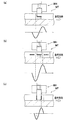
サーボ信号は、サーボライタの書込ヘッドに、磁気テープの一部を所定の方向に磁化する磁場を生じさせる記録電流(パルス信号)を印加することで書き込むことができる。具体的には、水平磁気記録では、図8(a)に示すように、磁化されていない磁気テープMTの一部を書込ヘッドWHにより長手方向(図の左右方向)の一方向に磁化することでサーボ信号を書き込むことができる。また、図8(b)に示すように、長手方向の一方向に磁化した磁気テープMTの一部を書込ヘッドWHにより一方向とは逆方向に磁化することによってもサーボ信号を書き込むことができる(特許文献1)。一方、垂直磁気記録では、図8(c)に示すように、磁化されていない磁気テープMTの一部を書込ヘッドWHにより厚み方向(図の上下方向)に磁化することでサーボ信号を書き込むことができる。このようにして書き込まれたサーボ信号を読み取ると、互いに逆極性の一対のピークを有する波形の読取信号を得ることができる。 The servo signal can be written by applying a recording current (pulse signal) that generates a magnetic field that magnetizes a part of the magnetic tape in a predetermined direction to the write head of the servo writer. Specifically, the horizontal magnetic recording recording, as shown in FIG. 8 (a), a part of the magnetic tape MT is not magnetized in one direction in the longitudinal direction by the write head WH (left and right direction in the drawing) Servo signals can be written by magnetizing. As shown in FIG. 8B, the servo signal can also be written by magnetizing a part of the magnetic tape MT magnetized in one direction in the longitudinal direction in the direction opposite to the one direction by the write head WH. Yes (Patent Document 1). On the other hand, in the vertical magnetic recording recording, the servo signal by magnetization as shown in FIG. 8 (c), the thickness direction a portion of the magnetic tape MT is not magnetized by the write head WH (vertical direction in the drawing) Can be written. When the servo signal written in this way is read, a read signal having a waveform having a pair of peaks of opposite polarities can be obtained.
ところで、特許文献2には、磁気ヘッドのトラッキング制御に、単一極性のピークを有する波形の信号(以下、本明細書において「単極パルス」という。)を用いることが記載されている。このような単極パルスを用いると、磁気テープの長手方向においてサーボ信号の書き込み密度を高めることが可能となるので、結果として磁気ヘッドのトラッキング制御の高速化が可能となる。
By the way,
しかしながら、前記した特許文献2には、単極パルスを得るための具体的な手法が開示されていなかった。
However, the above-described
そこで、本発明は、単極パルスを得ることができるサーボ信号が書き込まれた磁気テープの製造方法およびサーボライタを提供することを目的とする。 The present invention aims to provide a manufacturing how you and a servo writer of the magnetic tape servo signal is written can be obtained unipolar pulses.
前記した目的を達成するための本発明は、磁気ギャップを有する書込ヘッドによりサーボ信号が書き込まれたデータ記録用の磁気テープの製造方法であって、磁気テープを厚み方向の一方向に磁化する垂直直流消磁工程と、前記垂直直流消磁工程の後に、前記書込ヘッドにパルス信号を出力することで磁気テープにサーボ信号を書き込む信号書込工程と、を有し、前記信号書込工程は、前記書込ヘッドの磁気ギャップを形成する磁性体の一対のエッジ部のうち磁気テープの走行方向上流側のエッジ部で生じる磁場の垂直成分の方向が、前記一方向とは逆方向となるパルス信号により磁気テープにサーボ信号を書き込むことを特徴とする。 The present invention for achieving the above object is a method of manufacturing a magnetic tape for data recording in which a servo signal is written by a write head having a magnetic gap, and magnetizes the magnetic tape in one direction in the thickness direction. A vertical DC demagnetization step, and a signal writing step of writing a servo signal to the magnetic tape by outputting a pulse signal to the write head after the vertical DC demagnetization step, the signal writing step, A pulse signal in which the direction of the vertical component of the magnetic field generated at the edge portion on the upstream side in the running direction of the magnetic tape among the pair of edge portions of the magnetic material forming the magnetic gap of the write head is opposite to the one direction. you and writes the servo signal on a magnetic tape by.
このようなサーボ信号が書き込まれた磁気テープの製造方法によると、磁気テープに対し、厚み方向の一方向に磁化した部分と、当該一方向とは逆方向に磁化した部分(サーボ信号を構成する部分)とを形成することができる。これにより、サーボ信号を読み取ったときには、厚み方向の一方向に磁化した部分に対応するバックグラウンドに対し、当該一方向とは逆方向に磁化した部分に対応するピークが現れる波形の単極パルスを得ることができる。 According to the method of manufacturing a magnetic tape in which such a servo signal is written, a portion magnetized in one direction in the thickness direction and a portion magnetized in the opposite direction to the one direction (constituting a servo signal) Part). Thus, when the servo signal is read, a monopolar pulse having a waveform in which a peak corresponding to a portion magnetized in the direction opposite to the one direction appears with respect to the background corresponding to the portion magnetized in one direction in the thickness direction. Can be obtained.
ここで、本発明における磁気テープは、磁気テープの厚み方向に磁化した磁化成分(磁性体の極の厚み方向に向いた成分)の角形比(以下、本明細書において「垂直SQ」という。)が0.5以上であることが望ましい。なお、上記した垂直SQの値は、反磁界補正後の数値である。 Here, magnetic tape that put the present invention, the squareness ratio of the magnetic components magnetized in the thickness direction of the magnetic tape (component oriented in the thickness direction of the poles of the magnetic material) (hereinafter, "vertical SQ" herein Is preferably 0.5 or more. The value of the vertical SQ described above is a value after demagnetizing field correction.
なお、本明細書において、磁場の垂直成分とは、エッジ部で生じる磁場のうち、磁気テープに含まれる磁性体を磁気テープの厚み方向に磁化させる成分をいう。 In the present specification, the vertical component of the magnetic field refers to a component that magnetizes a magnetic material included in the magnetic tape in the thickness direction of the magnetic tape out of the magnetic field generated at the edge portion.
前記した製造方法においては、前記信号書込工程の前に実行され、前記書込ヘッドの磁気ギャップから漏れる磁場の水平成分の方向に倣って磁気テープを長手方向の一方向に磁化する水平直流消磁工程を有することが望ましい。 In the manufacturing method described above, the signal is executed before the writing step, the horizontal magnetizing the magnetic tape in the longitudinal direction in one direction following the direction of the horizontal component of the magnetic field leaking from the magnetic gap of the write head It is desirable to have a DC demagnetization process.
これによれば、磁気テープに含まれる磁性体のうち長手方向に向く成分を、長手方向における一方向(サーボ信号が書き込まれる部分と同じ方向)に揃えて磁化することができる。言い換えると、サーボ信号を構成する部分の長手方向に磁化した成分の向きと、それ以外の部分(バックグラウンド)の長手方向に磁化した成分の向きとを揃えることができる。これにより、サーボ信号を読み取ったときに、長手方向に磁化した成分に由来する信号(ノイズ)の強度を小さくすることができる。 According to this, the component oriented in the longitudinal direction of the magnetic material included in the magnetic tape can be magnetized by aligning in one direction in the longitudinal direction (the same direction as the portion where the servo signal is written). In other words, the direction of the component magnetized in the longitudinal direction of the portion constituting the servo signal can be aligned with the direction of the component magnetized in the longitudinal direction of the other portion (background). Thereby, when the servo signal is read, the intensity of the signal (noise) derived from the component magnetized in the longitudinal direction can be reduced.
なお、本明細書において、磁場の水平成分とは、エッジ部から漏れる磁場のうち、磁気テープに含まれる磁性体を磁気テープの長手方向に磁化させる成分をいう。 In the present specification, the horizontal component of the magnetic field refers to a component of the magnetic field leaking from the edge portion that magnetizes the magnetic material contained in the magnetic tape in the longitudinal direction of the magnetic tape.
前記した製造方法において、前記垂直直流消磁工程は、前記水平直流消磁工程の後に実行されることが望ましい。 In the manufacturing method described above, it is preferable that the vertical DC demagnetization step is performed after the horizontal DC demagnetization step.
この順番が逆になると、垂直直流消磁工程で厚み方向の一方向に磁化した磁性体の向きが、その後の水平直流消磁工程によって乱れ、サーボ信号を読み取ったときにノイズとなる可能性がある。そこで、水平直流消磁工程の後に垂直直流消磁工程を実行することで、前記したような磁性体の向きの乱れを抑制できるので、サーボ信号を読み取ったときのノイズを減らすことができる。 If this order is reversed, the orientation of the magnetic material magnetized in one direction in the thickness direction in the vertical DC demagnetization process may be disturbed by the subsequent horizontal DC demagnetization process, which may cause noise when the servo signal is read. Therefore, by executing the vertical DC demagnetization process after the horizontal DC demagnetization process, the above-described disturbance in the orientation of the magnetic material can be suppressed, and thus noise when the servo signal is read can be reduced.
また、長手方向に磁化した磁化成分(磁性体の極の長手方向に向いた成分)が、長手方向において同じ方向を向いていることで、サーボ信号を読み取ったときに、長手方向に磁化した成分に由来する信号(ノイズ)の強度を小さくすることができる。 In addition , the magnetized component magnetized in the longitudinal direction (the component oriented in the longitudinal direction of the magnetic pole) is oriented in the same direction in the longitudinal direction, so that when the servo signal is read, the component magnetized in the longitudinal direction The intensity of the signal (noise) derived from can be reduced.
また、前記した目的を達成するための本発明は、データ記録用の磁気テープにサーボ信号を書き込むサーボライタであって、磁気ギャップを有し、磁気テープにサーボ信号を書き込む書込ヘッドと、前記書込ヘッドにパルス信号を出力する信号出力部と、磁気テープの走行方向における前記書込ヘッドの上流側に設けられ、磁気テープを厚み方向の一方向に磁化する垂直直流消磁ヘッドと、を備え、前記信号出力部は、前記書込ヘッドの磁気ギャップを形成する磁性体の一対のエッジ部のうち磁気テープの走行方向上流側のエッジ部で生じる磁場の垂直成分の方向が、前記一方向とは逆方向となるパルス信号を出力することを特徴とする。 Further, the present invention for achieving the above object is a servo writer for writing a servo signal on a magnetic tape for data recording, having a magnetic gap, and a write head for writing a servo signal on the magnetic tape, A signal output unit that outputs a pulse signal to the write head; and a vertical DC demagnetization head that is provided upstream of the write head in the running direction of the magnetic tape and magnetizes the magnetic tape in one direction of the thickness direction. The signal output unit is configured such that a direction of a vertical component of a magnetic field generated at an edge portion on the upstream side in the running direction of the magnetic tape among the pair of edge portions of the magnetic material forming the magnetic gap of the write head is the one direction. It is you and outputs a pulse signal which becomes reverse.
このようなサーボライタによると、磁気テープに対し、厚み方向の一方向に磁化した部分と、当該一方向とは逆方向に磁化した部分(サーボ信号を構成する部分)とを形成することができる。これにより、サーボ信号を読み取ったときには、厚み方向の一方向に磁化した部分に対応するバックグラウンドに対し、当該一方向とは逆方向に磁化した部分に対応するピークが現れる波形の単極パルスを得ることができる。 According to such a servo writer, a portion magnetized in one direction of the thickness direction and a portion magnetized in the direction opposite to the one direction (portion constituting the servo signal) can be formed on the magnetic tape. . Thus, when the servo signal is read, a monopolar pulse having a waveform in which a peak corresponding to a portion magnetized in the direction opposite to the one direction appears with respect to the background corresponding to the portion magnetized in one direction in the thickness direction. Can be obtained.
前記したサーボライタにおいては、磁気テープの走行方向における前記書込ヘッドの上流側に設けられ、前記書込ヘッドの磁気ギャップから漏れる磁場の水平成分の方向に倣って磁気テープを長手方向の一方向に磁化する水平直流消磁ヘッドを備えることが望ましい。 In the service Boraita described above, disposed upstream of the write head in the running direction of the magnetic tape, the magnetic tape in the longitudinal direction following the direction of the horizontal component of the magnetic field leaking from the magnetic gap of the write head one It is desirable to have a horizontal DC degaussing head that magnetizes in the direction.
これによれば、水平直流消磁ヘッドにより、磁気テープに含まれる磁性体のうち長手方向に向く成分を、長手方向における一方向(サーボ信号が書き込まれる部分と同じ方向)に揃えて磁化することができる。その結果、サーボ信号を構成する部分の長手方向に磁化した成分の向きと、バックグラウンドの長手方向に磁化した成分の向きとを揃えることができるので、サーボ信号を読み取ったときに、長手方向に磁化した成分に由来する信号(ノイズ)の強度を小さくすることができる。 According to this, the horizontal DC demagnetizing head can magnetize the magnetic material included in the magnetic tape so that the component oriented in the longitudinal direction is aligned in one direction in the longitudinal direction (the same direction as the portion where the servo signal is written). it can. As a result, the direction of the component magnetized in the longitudinal direction of the portion constituting the servo signal can be aligned with the direction of the component magnetized in the longitudinal direction of the background. The intensity of the signal (noise) derived from the magnetized component can be reduced.
前記したサーボライタにおいて、前記垂直直流消磁ヘッドは、磁気テープの走行方向における前記水平直流消磁ヘッドの下流側に設けられることが望ましい。 In the servo writer described above, it is desirable that the vertical DC degaussing head is provided downstream of the horizontal DC degaussing head in the running direction of the magnetic tape.
これによれば、磁気テープを、長手方向の一方向に磁化した後に、厚み方向の一方向に磁化することができる。その結果、厚み方向の一方向に磁化した磁性体の向きの乱れを抑制できるので、サーボ信号を読み取ったときのノイズを減らすことができる。 According to this, the magnetic tape can be magnetized in one direction in the thickness direction after being magnetized in one direction in the longitudinal direction. As a result, since the disorder of the direction of the magnetic material magnetized in one direction of the thickness direction can be suppressed, noise when the servo signal is read can be reduced.
本発明によれば、サーボ信号を読み取ったときに、単極パルスを得ることができるので、磁気ヘッドのトラッキング制御を高速化することが可能となる。 According to the present invention, since a monopolar pulse can be obtained when a servo signal is read, the tracking control of the magnetic head can be speeded up.
[第1実施形態]
次に、本発明の第1実施形態について、適宜図面を参照しながら詳細に説明する。
[First Embodiment]
Next, a first embodiment of the present invention will be described in detail with reference to the drawings as appropriate.
<磁気テープ>
まず、実施形態に係るサーボ信号が書き込まれた磁気テープについて説明する。
図1に示すように、磁気テープMTは、いわゆる垂直磁気記録が可能な磁気テープであり、主に、ベースフィルムBと、ベースフィルムB上に形成された磁性層Mとを備えて構成されている。
<Magnetic tape>
First, a magnetic tape on which servo signals according to the embodiment are written will be described.
As shown in FIG. 1, the magnetic tape MT is a magnetic tape capable of so-called perpendicular magnetic recording, and mainly includes a base film B and a magnetic layer M formed on the base film B. Yes.
ベースフィルムBは、磁性層Mを支持するための支持体であり、一例としてポリエチレンテレフタレート(PET)などからなる。 The base film B is a support for supporting the magnetic layer M, and is made of, for example, polyethylene terephthalate (PET).
磁性層Mは、データやサーボ信号が磁気パターンとして書き込まれる層であり、磁性体の粉末やバインダーなどを混合した磁性塗料をベースフィルムB上に塗布し、乾燥させることで形成される。磁性体は、データやサーボ信号が書き込まれたときに、磁気テープMTの厚み方向(以下、単に「厚み方向」という。)に磁化する成分を残すことができる磁性体であれば、特に限定されず、例えば、バリウムフェライトやストロンチウムフェライトなどの六方晶フェライト磁性体を用いることができる。なお、バインダーの種類は特に限定されない。また、磁性層Mは、カーボンブラックや公知の研磨剤、潤滑剤などを含んでいてもよい。さらに、本発明において、磁気テープMTは、公知の非磁性層やバックコート層などを有していてもよい。 The magnetic layer M is a layer in which data and servo signals are written as a magnetic pattern. The magnetic layer M is formed by applying a magnetic paint mixed with a magnetic powder, a binder, etc. on the base film B and drying it. The magnetic material is not particularly limited as long as it can leave a component that is magnetized in the thickness direction of the magnetic tape MT (hereinafter simply referred to as “thickness direction”) when data or servo signals are written. For example, a hexagonal ferrite magnetic material such as barium ferrite or strontium ferrite can be used. In addition, the kind of binder is not specifically limited. Moreover, the magnetic layer M may contain carbon black, a well-known abrasive | polishing agent, a lubrication agent, etc. Furthermore, in the present invention, the magnetic tape MT may have a known nonmagnetic layer, backcoat layer, and the like.
磁気テープMTは、前記したように垂直磁気記録が可能な磁気テープである。このような磁気テープMTでは、磁性層Mに含まれる磁性体(磁気双極子)が厚み方向に磁化することで、データの記録やサーボ信号の書き込みが行われる。そのため、本発明で使用する磁気テープMTの磁性層Mに含まれる磁性体は、厚み方向に向く成分(磁化しやすい成分)の割合が大きいこと(垂直SQが0.5以上であること)が望ましい。 The magnetic tape MT is a magnetic tape capable of perpendicular magnetic recording as described above. In such a magnetic tape MT, the magnetic material (magnetic dipole) included in the magnetic layer M is magnetized in the thickness direction, whereby data recording and servo signal writing are performed. Therefore, the magnetic substance contained in the magnetic layer M of the magnetic tape MT used in the present invention has a large proportion of components (components that are easily magnetized) oriented in the thickness direction (the vertical SQ is 0.5 or more). desirable.
ちなみに、従来の水平磁気記録に用いられる磁気テープに対し、交流磁場(磁性層が全体として磁気的に無配向となるような磁場)を加えた場合の垂直SQは高々0.2〜0.3程度である。一方、近年、垂直磁気記録に用いられる磁気テープとして研究されている、バリウムフェライト磁性体を用いた磁気テープに対し、交流磁場を加えた場合の垂直SQは0.54〜0.57である。 Incidentally, the vertical SQ when an alternating magnetic field (a magnetic field in which the magnetic layer becomes magnetically non-oriented as a whole) is applied to a magnetic tape used for conventional horizontal magnetic recording is 0.2 to 0.3 at most. Degree. On the other hand, the perpendicular SQ when an alternating magnetic field is applied to a magnetic tape using a barium ferrite magnetic material, which has been recently studied as a magnetic tape used for perpendicular magnetic recording , is 0.54 to 0.57.
なお、本発明においては、一方側(例えば正側)に出力される単極パルスの強度が、これとは反対側(負側)に出力されるノイズなどの成分の強度よりも大きいことが重要であり、これを実現することができる垂直SQの値は、使用する磁性体によって多少変わりうる。 In the present invention, it is important that the intensity of the monopolar pulse output on one side (for example, the positive side) is larger than the intensity of components such as noise output on the opposite side (negative side). The value of the vertical SQ that can realize this can vary somewhat depending on the magnetic material used.
磁気テープMT(磁性層M)は、公知の磁気テープドライブによりデータが記録されるデータバンドDBと、サーボ信号(サーボパターンSP)が書き込まれたサーボバンドSBとを有している。図1,2(a)に示すように、サーボバンドSBは、厚み方向の一方向に磁化した第1部分S1と、厚み方向において一方向とは逆方向に磁化した第2部分S2とを有している。なお、以下においては、説明をわかりやすくするため、図2(a)などに示す方向に対応させて、「厚み方向の一方向」を「下方向」といい、「厚み方向において一方向とは逆方向」を「上方向」ということがある。 The magnetic tape MT (magnetic layer M) has a data band DB in which data is recorded by a known magnetic tape drive, and a servo band SB in which a servo signal (servo pattern SP) is written. As shown in FIGS. 1 and 2A, the servo band SB has a first portion S1 magnetized in one direction in the thickness direction and a second portion S2 magnetized in the direction opposite to the one direction in the thickness direction. doing. In the following, in order to make the explanation easy to understand, “one direction in the thickness direction” is referred to as “downward direction” in correspondence with the direction shown in FIG. “Reverse direction” is sometimes referred to as “upward direction”.
サーボバンドSBの第1部分S1は、サーボバンドSBのうち、サーボ信号を構成しない部分であり、後述するように、磁気テープMTの製造工程において、磁気テープMTの磁性層Mを下方向に磁化する垂直直流消磁工程を実行することで形成される。 The first portion S1 of the servo band SB is a portion of the servo band SB that does not constitute a servo signal. As will be described later, in the magnetic tape MT manufacturing process, the magnetic layer M of the magnetic tape MT is magnetized downward. It is formed by executing a vertical DC demagnetization process.
第2部分S2は、サーボバンドSBのうち、サーボ信号を構成する部分である。具体的に、磁気パターンとしてのサーボ信号は、図1に示すように、サーボパターンSPがサーボバンドSBの長手方向において所定間隔で書き込まれることで構成されている。なお、本発明において、サーボパターンSPの形状は特に限定されず、例えば、図1に示すような、非平行な少なくとも1組のストライプ形状(略ハ字形状)のパターンとすることができる。 The second portion S2 is a portion constituting a servo signal in the servo band SB. Specifically, the servo signal as the magnetic pattern is configured by writing the servo pattern SP at a predetermined interval in the longitudinal direction of the servo band SB as shown in FIG. In the present invention, the shape of the servo pattern SP is not particularly limited. For example, it can be a non-parallel pattern of at least one set of stripes (substantially C-shaped) as shown in FIG.
このような下方向に磁化した第1部分S1と上方向に磁化したサーボ信号を構成する第2部分S2とを有するサーボバンドSBを、公知の磁気ヘッド(読取素子)により読み取ると、図2(b)に示すように、第1部分S1に対応するバックグラウンド(図において0で示すライン)に対し、第2部分S2に対応する単一極性のピークが現れる波形の読取信号(単極パルス)を得ることができる。 When the servo band SB having the first portion S1 magnetized in the downward direction and the second portion S2 constituting the servo signal magnetized in the upward direction is read by a known magnetic head (reading element), FIG. As shown in b), a read signal (monopolar pulse) having a waveform in which a single polarity peak corresponding to the second portion S2 appears with respect to the background corresponding to the first portion S1 (line indicated by 0 in the figure). Can be obtained.
図2(a)に示すように、サーボバンドSB(磁性層M)は、厚み方向に磁化した磁化成分(磁性体の極の厚み方向に向いた成分)のほか、さらに、長手方向に磁化した磁化成分(磁性体の極の長手方向に向いた成分)を有している。そして、この長手方向に磁化した磁化成分は、磁気モーメントが長手方向の一方(図の左方向)に偏っている(長手方向の一方向に磁気モーメントが向いている)。これにより、サーボ信号(サーボパターンSP)を読み取ったときに、長手方向に磁化した成分に由来する信号(ノイズ)の強度を小さくすることができる。 As shown in FIG. 2A, the servo band SB (magnetic layer M) is magnetized in the longitudinal direction in addition to the magnetization component magnetized in the thickness direction (component oriented in the thickness direction of the magnetic pole). It has a magnetization component (component oriented in the longitudinal direction of the magnetic pole). In the magnetization component magnetized in the longitudinal direction, the magnetic moment is biased to one of the longitudinal directions (the left direction in the figure) (the magnetic moment is directed in one longitudinal direction). Thereby, when the servo signal (servo pattern SP) is read, the intensity of the signal (noise) derived from the component magnetized in the longitudinal direction can be reduced.
なお、データバンドDBは、データが記録される前は概念上のものであり、本発明において、データバンドDBに含まれる磁性体は、厚み方向の一方向や長手方向の一方向に磁化されていてもよいし、磁化されていなくてもよい(全体として磁気的に無配向であってもよい)。 The data band DB is conceptual before data is recorded. In the present invention, the magnetic material included in the data band DB is magnetized in one direction in the thickness direction or one direction in the longitudinal direction. Or may not be magnetized (may be magnetically non-oriented as a whole).
<サーボライタ>
次に、磁気テープMTを製造するためのサーボライタの構成について説明する。
図3に示すように、サーボライタ1は、主に磁気テープMTにサーボ信号を書き込む装置であり、ベース10上に、磁気テープ搬送装置20と、書込ヘッド30と、ベリファイヘッド40と、水平直流消磁ヘッド50と、垂直直流消磁ヘッド60とを主に備えている。
<Servo writer>
Next, the configuration of the servo writer for manufacturing the magnetic tape MT will be described.
As shown in FIG. 3, the
磁気テープ搬送装置20は、サーボ信号を書き込む前の磁気テープMTを巻回した巻出しリール21と、サーボ信号を書き込んだ後の磁気テープMTを巻き取る巻取りリール22と、巻出しリール21から供給された磁気テープMTを巻取りリール22まで案内する複数のガイドローラ23およびテープガイド24とを主に備えて構成されている。巻出しリール21は、巻出しモータ21Aによって回転駆動し、巻取りリール22は、巻取りモータ22Aによって回転駆動するように構成されている。
The magnetic
書込ヘッド30は、磁気テープMTにサーボ信号(サーボパターンSP)を書き込むための磁気ヘッドであり、略板状に形成され、磁気テープMTと摺接(対面)する面にサーボパターンSPを象った磁気ギャップG(図4(c)参照)を有している。
The
図4(c)に示すように、書込ヘッド30の磁気ギャップGは、膜状の磁性体31(磁性薄膜)に対し、図4に示す方向から見て、磁気テープMTの走行方向(長手方向)に開くように形成されている。なお、以下の説明においては、書込ヘッド30の磁気ギャップGを形成する磁性体31の一対のエッジ部(EL,ET)のうち、磁気テープMTの走行方向における上流側(図の左側)のエッジ部をリーディングエッジELといい、下流側(図の右側)のエッジ部をトレーリングエッジETという。
As shown in FIG. 4C, the magnetic gap G of the
書込ヘッド30には、書込ヘッド30にサーボパターンSPを書き込むためのパルス信号を出力する信号出力部30A(図3参照)が接続されている。本実施形態において、信号出力部30Aは、サーボ信号を書き込むとき、書込ヘッド30の磁気ギャップG付近に、トレーリングエッジETから磁性層Mの内部を通ってリーディングエッジELに向かう磁束(破線参照)が形成されるような極性のパルス信号を出力する。
The
サーボライタ1では、磁気テープ搬送装置20により磁気テープMTを搬送し、書込ヘッド30に磁気テープMTを摺接させながら、信号出力部30Aが書込ヘッド30に適宜なタイミングでパルス信号を繰り返し出力することで、磁気テープMT(サーボバンドSB)に対し、サーボパターンSPが長手方向に所定間隔で繰り返されるサーボ信号が書き込まれる。
In the
図3に示すように、ベリファイヘッド40は、磁気テープMTに書き込まれたサーボ信号の品質を確認するための磁気ヘッドであり、磁気テープMTの走行方向(以下、単に「走行方向」という。)における書込ヘッド30の下流側に設けられている。図示は省略するが、ベリファイヘッド40には、磁気テープMTの幅方向においてサーボバンドSBと対応した位置に公知の読取素子が設けられている。
As shown in FIG. 3, the verify
ベリファイヘッド40には、読取素子でサーボ信号を読み取って得た電気信号から、サーボ信号(サーボパターンSP)の品質をPES(Position Error Signal:磁気テープMTの幅方向への振れ)として演算するPES演算部40Aが接続されている。サーボライタ1では、PES演算部40Aが演算したPESの値に基づいて磁気テープMTに書き込まれたサーボ信号の品質を確認している。
The verify
水平直流消磁ヘッド50は、磁気テープMT(磁性体のうち長手方向に向く成分)をその長手方向の一方向に磁化する磁気ヘッドであり、走行方向における書込ヘッド30および垂直直流消磁ヘッド60の上流側に設けられている。図4(a)に示すように、水平直流消磁ヘッド50は、磁性層Mの内部において長手方向に沿った磁束(破線参照)を形成しており、走行する磁気テープMTの水平直流消磁ヘッド50よりも下流側を長手方向の一方向(図の左方向)に磁化する。本実施形態において、水平直流消磁ヘッド50は、書込ヘッド30の磁気ギャップGから漏れる磁場の水平成分H(図4(c)参照)の方向に倣って磁気テープMTを長手方向の一方向(水平成分Hと同じ方向)に磁化している。
The horizontal direct
このような水平直流消磁ヘッド50の構成は特に限定されず、永久磁石から構成されていてもよいし、電磁石から構成されていてもよい。また、水平直流消磁ヘッド50で磁気テープMTを磁化するときの磁束密度は、例えば、磁性層M(磁性体)の保磁力が238.7kA/m(3000 Oe)である場合、0.3T以上が好ましく、0.5T以上がより好ましい。
The configuration of such a horizontal
垂直直流消磁ヘッド60は、磁気テープMT(磁性体のうち厚み方向に向く成分)をその厚み方向の一方向に磁化する磁気ヘッドであり、走行方向における水平直流消磁ヘッド50の下流側、かつ、書込ヘッド30の上流側(水平直流消磁ヘッド50と書込ヘッド30の間)に設けられている。図4(b)に示すように、垂直直流消磁ヘッド60は、厚み方向に沿って磁気テープMTを貫くように磁性層M側からベースフィルムB側に向かう磁束(破線参照)を形成しており、磁気テープMTを下方向(厚み方向の一方向)に磁化する。
The vertical
このような垂直直流消磁ヘッド60の構成は特に限定されず、永久磁石から構成されていてもよいし、電磁石から構成されていてもよい。また、垂直直流消磁ヘッド60で磁気テープMTを磁化するときの磁束密度は、例えば、磁性層M(磁性体)の保磁力が238.7kA/m(3000 Oe)である場合、0.3T以上が好ましく、0.5T以上がより好ましい。
The configuration of such a vertical
<磁気テープの製造方法>
次に、サーボライタ1を用いた磁気テープMTの製造方法について説明する。
まず、サーボ信号を書き込む前の磁気テープMTをサーボライタ1にセットした後、巻出しモータ21Aおよび巻取りモータ22Aを駆動させて、磁気テープMTを巻出しリール21から巻取りリール22に向けて走行させる。
<Method of manufacturing magnetic tape>
Next, a method for manufacturing the magnetic tape MT using the
First, after setting the magnetic tape MT before the servo signal is written in the
その走行途中において、図4(a)に示すように、まずは、磁気テープMTの磁性層M(磁性体のうち長手方向に向く成分)を、水平直流消磁ヘッド50により図示左方向(長手方向の一方向)に磁化する(水平直流消磁工程)。
During the running, as shown in FIG. 4A, first, the magnetic layer M of the magnetic tape MT (the component of the magnetic material facing in the longitudinal direction) is first moved in the left direction (longitudinal direction) by the horizontal
次に、図4(b)に示すように、磁気テープMTの磁性層M(磁性体のうち厚み方向に向く成分)を、水平直流消磁ヘッド50の下流側に設けられた垂直直流消磁ヘッド60により図示下方向(厚み方向の一方向)に磁化する(垂直直流消磁工程)。
Next, as shown in FIG. 4B, the vertical
垂直直流消磁工程の後、信号出力部30Aから書込ヘッド30にパルス信号を出力することで磁気テープMTにサーボ信号(サーボパターンSP)を書き込む(信号書込工程)。この信号書込工程において、信号出力部30Aは、図4(c)に示すように、リーディングエッジELで生じる磁場の垂直成分P1の方向が、図示上方向(長手方向の一方向とは逆方向)となるような極性のパルス信号(記録電流)を出力する。このとき、トレーリングエッジETでは、垂直成分P2の方向が下方向(厚み方向の一方向と同一方向)となる磁場が生じる。
After the vertical DC demagnetization process, a servo signal (servo pattern SP) is written on the magnetic tape MT by outputting a pulse signal from the
これにより、リーディングエッジELで生じる磁場の垂直成分P1によって磁性体が垂直直流消磁工程で磁化された方向とは逆方向の上方向に磁化されてサーボパターンSPとして残り、サーボ信号を構成する。また、トレーリングエッジETで生じる磁場の垂直成分P2の影響を受ける磁性体は、垂直直流消磁工程によってすでに垂直成分P2と同じ下方向に磁化されているので、磁化状態がそのまま維持されることとなる。以上より、本実施形態においては、リーディングエッジELで磁化された磁性体のみが、サーボ信号(サーボパターンSP)として磁気テープMTに書き込まれることとなる。 As a result, the magnetic material is magnetized upward in the direction opposite to the direction magnetized in the vertical DC demagnetization process by the vertical component P1 of the magnetic field generated at the leading edge EL, and remains as the servo pattern SP, thereby constituting a servo signal. Further, since the magnetic body affected by the vertical component P2 of the magnetic field generated at the trailing edge ET has already been magnetized in the same downward direction as the vertical component P2 by the vertical DC demagnetization process, the magnetization state is maintained as it is. Become. As described above, in the present embodiment, only the magnetic material magnetized by the leading edge EL is written on the magnetic tape MT as a servo signal (servo pattern SP).
その後、磁気テープMTに書き込まれたサーボ信号(サーボパターンSP)をベリファイヘッド40で読み取って、PES演算部40AでPESの値を演算してサーボ信号の品質を確認しながら、磁気テープMTを巻取りリール22に巻き取っていく。そして、巻き取った磁気テープMTを、公知のカートリッジケースに収容することで、サーボ信号が書き込まれた磁気テープMT(磁気テープカートリッジ)が製造される。
Thereafter, the servo signal (servo pattern SP) written on the magnetic tape MT is read by the verify
図8(c)に示すように、交流消磁を行うなどして、磁化されていない(全体として磁気的に無配向な)垂直磁気記録に用いられる磁気テープMTに、磁気ギャップを有する書込ヘッドWHでサーボ信号を書き込んだ場合、下方向に磁化された磁性体と上方向に磁化された磁性体とからなる一対の磁気パターンが形成され、この磁気パターンが所定間隔で繰り返されることでサーボ信号が形成される。このような磁気テープMTを読み取った場合、互いに逆極性の一対のピークを有する波形を繰り返す読取信号が得られ、単極パルスを得ることはできない。 As shown in FIG. 8C, a write head having a magnetic gap on a magnetic tape MT used for perpendicular magnetic recording that is not magnetized (generally magnetically non-oriented) by performing AC demagnetization or the like. When a servo signal is written by WH, a pair of magnetic patterns consisting of a magnetic material magnetized in the downward direction and a magnetic material magnetized in the upward direction are formed, and the servo signal is repeated by repeating the magnetic pattern at a predetermined interval. Is formed. When such a magnetic tape MT is read, a read signal that repeats a waveform having a pair of peaks with opposite polarities is obtained, and a monopolar pulse cannot be obtained.
一方、本実施形態のサーボライタ1および磁気テープMTの製造方法により製造された磁気テープMTでは、サーボバンドSBが、垂直直流消磁工程により下方向に磁化した第1部分S1と、信号書込工程により上方向に磁化した第2部分S2とを有することになるので、磁気パターン(サーボ信号)を構成するのは上方向に磁化した部分だけとなる。このような磁気テープMT(サーボ信号)を読み取ったときには、図2(b)に示すような、単一極性のピークを有する単極パルスを得ることができる。
On the other hand, in the magnetic tape MT manufactured by the
これにより、磁気テープMTの長手方向において、サーボ信号の書き込み密度を高める(隣り合うサーボパターンSP同士の間隔を小さくする)ことが可能となる。その結果、トラッキング制御の際に、読取信号のピーク間の時間間隔を短くできるので、磁気ヘッドのトラッキング制御を高速化することが可能となる。 This makes it possible to increase the writing density of servo signals (to reduce the interval between adjacent servo patterns SP) in the longitudinal direction of the magnetic tape MT. As a result, since the time interval between the peaks of the read signal can be shortened during tracking control, the tracking control of the magnetic head can be speeded up.
また、図2(a),図4に示すように、磁気テープMTに含まれる磁性体のうち長手方向に向く成分を、長手方向において同じ方向に磁化させているので、サーボ信号を読み取ったときに、長手方向に磁化した成分に由来する信号(ノイズ)の強度を小さくすることができる。 Further, as shown in FIGS. 2A and 4, since the components oriented in the longitudinal direction of the magnetic material included in the magnetic tape MT are magnetized in the same direction in the longitudinal direction, the servo signal is read. In addition, the intensity of the signal (noise) derived from the component magnetized in the longitudinal direction can be reduced.
さらに、垂直直流消磁ヘッド60を水平直流消磁ヘッド50の下流側に設け、水平直流消磁工程の後に垂直直流消磁工程を実行するようにしたので、厚み方向の一方向に磁化した磁性体の向きの乱れを抑制でき、サーボ信号を読み取ったときのノイズを減らすことができる。
Furthermore, since the vertical
[第2実施形態]
次に、第2実施形態について説明する。なお、本実施形態では、前記した第1実施形態と同様の構成要素については、同一符号を付して、その説明を省略することとする。
[Second Embodiment]
Next , a second embodiment will be described. In the present embodiment, the same components as those in the first embodiment are denoted by the same reference numerals, and the description thereof is omitted.
前記した第1実施形態では、リーディングエッジELで磁化された磁性体がサーボ信号として磁気テープMTに書き込まれる形態を説明した。本実施形態は、トレーリングエッジETで磁化された磁性体がサーボ信号として磁気テープMTに書き込まれる形態である。 In the first embodiment described above, the mode in which the magnetic material magnetized by the leading edge EL is written on the magnetic tape MT as a servo signal has been described. In the present embodiment, a magnetic material magnetized at the trailing edge ET is written on the magnetic tape MT as a servo signal.
具体的に、本実施形態では、信号書込工程において、サーボライタ1の信号出力部30Aは、図5(a)に示すように、トレーリングエッジETで生じる磁場の垂直成分P2の方向が、垂直直流消磁工程で磁化した方向(図の下方向)とは逆方向(図の上方向)となるような極性のパルス信号(記録電流)を出力する。言い換えると、本実施形態では、信号書込工程において、信号出力部30Aが、前記第1実施形態の信号書込工程の場合とは通電方向が逆向きとなる記録電流(パルス信号)を出力する。
Specifically, in the present embodiment, in the signal writing process, the
これによれば、前記第1実施形態の場合とは逆に、トレーリングエッジETで生じる磁場の垂直成分P2によって磁性体が垂直直流消磁工程で磁化された方向とは逆方向の上方向に磁化されてサーボパターンSPとして残り、サーボ信号を構成する。また、リーディングエッジELで生じる磁場の垂直成分P1の影響を受ける磁性体は、垂直直流消磁工程によってすでに垂直成分P1と同じ下方向に磁化されているので、磁化状態がそのまま維持されることとなる。 According to this, contrary to the case of the first embodiment, the magnetic material is magnetized upward in the direction opposite to the direction magnetized in the vertical DC demagnetization process by the vertical component P2 of the magnetic field generated at the trailing edge ET. As a result, the servo pattern SP remains as a servo signal. Further, since the magnetic material affected by the vertical component P1 of the magnetic field generated at the leading edge EL has already been magnetized in the same downward direction as the vertical component P1 by the vertical DC demagnetization process, the magnetization state is maintained as it is. .
なお、本実施形態では、水平直流消磁工程において、磁気テープMTを、前記第1実施形態の水平直流消磁工程の場合とは逆方向の図示右方向に磁化することが望ましい。具体的には、例えば、図4(a)に示す水平直流消磁ヘッド50のN極同士を磁気テープMTを挟んで向かい合わせることで、前記第1実施形態の水平直流消磁工程の場合とは逆方向に磁気テープMTを磁化することができる。これによれば、水平直流消磁工程で長手方向に磁化する向きと、信号書込工程で書込ヘッド30により長手方向に磁化する向きとを揃えることができるので、サーボ信号を読み取ったときにノイズの強度を小さくすることができる。
In the present embodiment, in the horizontal DC demagnetization process, it is desirable to magnetize the magnetic tape MT in the right direction in the figure, which is the opposite direction to that in the horizontal DC demagnetization process of the first embodiment. Specifically, for example, the N-poles of the horizontal
本実施形態においては、信号出力部30Aが出力するパルス信号の出力時間(記録電流の通電時間)を調整することで、読取信号のパルス幅を調整することが可能となっている。具体的に、本実施形態では、トレーリングエッジETで磁化された磁性体がサーボ信号として残るので、図5(b),(c)に示すように、パルス信号の出力時間が長くなると、サーボ信号(上方向に磁化した部分)が長手方向に長くなっていく。これにより、パルス信号の出力時間を調整することで、上方向に磁化した部分(サーボパターンSP)の長手方向における長さを調整でき、図5(d)に示すように、読取信号のパルス幅を調整することが可能となる。
In the present embodiment, the pulse width of the read signal can be adjusted by adjusting the output time of the pulse signal output by the
ちなみに、前記第1実施形態のように、リーディングエッジELで磁化された磁性体がサーボ信号として残る形態では、パルス信号の出力時間などが多少ぶれても、リーディングエッジELで上方向に磁化した磁性体(ぶれた分)が、トレーリングエッジETにより下方向に磁化されることで、いわば打ち消されることになるので、長手方向に安定した長さでサーボパターンSPを書き込むことができる。 Incidentally, in the form in which the magnetic material magnetized at the leading edge EL remains as a servo signal as in the first embodiment, the magnetism magnetized upward at the leading edge EL even if the output time of the pulse signal is somewhat shifted. Since the body (blurred part) is magnetized downward by the trailing edge ET, it is canceled out, so that the servo pattern SP can be written with a stable length in the longitudinal direction.
以上、本発明の実施形態について説明したが、本発明は前記実施形態に限定されるものではない。具体的な構成については、本発明の趣旨を逸脱しない範囲で適宜変更が可能である。 As mentioned above, although embodiment of this invention was described, this invention is not limited to the said embodiment. About a concrete structure, it can change suitably in the range which does not deviate from the meaning of this invention.
前記実施形態では、垂直直流消磁ヘッド60を水平直流消磁ヘッド50の下流側に設け、水平直流消磁工程の後に垂直直流消磁工程を実行したが、本発明はこれに限定されず、この順番が逆であってもよい。すなわち、垂直直流消磁ヘッドを水平直流消磁ヘッドの上流側に設け、垂直直流消磁工程の後(かつ信号書込工程の前)に水平直流消磁工程を実行してもよい。ただし、前記したように、水平直流消磁工程の後に垂直直流消磁工程を実行することで、サーボ信号を読み取ったときのノイズを減らすことができる。
In the above embodiment, the vertical
前記実施形態では、水平直流消磁工程を有する磁気テープMTの製造方法(水平直流消磁ヘッド50を備えるサーボライタ1)を示したが、本発明はこれに限定されず、水平直流消磁工程(水平直流消磁ヘッド)を省略してもよい。すなわち、磁気テープのサーボバンドは、長手方向に磁化した磁化成分が長手方向の一方および他方のうちのいずれかに偏っていなくてもよい(長手方向に関して無配向であってもよい)。ただし、前記したように、磁性体のうち長手方向に向く成分の向きを揃えることで、サーボ信号を読み取ったときのノイズの強度を小さくすることができる。
In the above embodiment, the method of manufacturing the magnetic tape MT having the horizontal direct current demagnetization process (
前記実施形態では、水平直流消磁ヘッド50および垂直直流消磁ヘッド60を備えるサーボライタ1により、サーボ信号が書き込まれた磁気テープMTを製造したが、本発明はこれに限定されるものではない。すなわち、水平直流消磁工程、垂直直流消磁工程および信号書込工程は、別々の設備(装置)で行ってもよい。なお、垂直直流消磁工程や水平直流消磁工程は、ベースフィルム上に塗布した磁性塗料を乾燥させた後から、サーボ信号を書き込む前までの間であれば、いつ実行してもよい。
In the embodiment, the magnetic tape MT on which the servo signal is written is manufactured by the
次に、本発明の効果を確認した実施例について説明する。 Next, examples in which the effects of the present invention have been confirmed will be described.
<単極パルス生成の確認>
まず、本発明の磁気テープの製造方法によって、単極パルスを得ることができる磁気テープを製造できることを確認した。
<Confirmation of unipolar pulse generation>
First, it was confirmed that a magnetic tape capable of obtaining a monopolar pulse could be manufactured by the magnetic tape manufacturing method of the present invention.
(実施例1)
前記第1実施形態で説明した製造方法により、以下の条件で、磁気テープにリーディングエッジでサーボ信号を書き込んで、サーボ信号が書き込まれた磁気テープ(実施例1)を製造した。その後、当該磁気テープを読み取り、オシロスコープで図6(a)に示す波形(読取信号)を取得した。
磁気テープの走行速度(書込時・読取時) 4m/s
書込時のパルス信号の出力時間 50ns,250ns
垂直直流消磁工程と水平直流消磁工程の磁束密度 0.7T
Example 1
The manufacturing method described in the first embodiment, under the following conditions, by writing servo signals on the leading edge magnetic tape was produced magnetic tape (Example 1) in which the servo signal is written. Thereafter, the magnetic tape was read, and a waveform (read signal) shown in FIG.
Magnetic tape running speed (during writing / reading) 4m / s
Pulse signal output time during writing 50ns, 250ns
Magnetic flux density of vertical DC demagnetization process and horizontal DC demagnetization process 0.7T
(比較例2)
前記第2実施形態で説明した製造方法により、実施例1と同じ条件で、磁気テープにトレーリングエッジでサーボ信号を書き込んで、サーボ信号が書き込まれた磁気テープ(比較例2)を製造した。なお、比較例2においても、水平直流消磁工程を実行することで、磁気テープの長手方向に向く成分の向きを揃えた。その後、当該磁気テープを読み取り、オシロスコープで図6(b)に示す読取信号を取得した。
( Comparative Example 2)
By the manufacturing method described in the second embodiment, under the same conditions as in Example 1, a servo signal was written on the magnetic tape at the trailing edge to manufacture a magnetic tape on which the servo signal was written ( Comparative Example 2). In Comparative Example 2 as well, the horizontal direct current demagnetization step was performed to align the components facing the longitudinal direction of the magnetic tape. Thereafter, the magnetic tape was read, and a read signal shown in FIG.
(結果)
図6(a),(b)から、本発明の磁気テープの製造方法、磁気テープおよびサーボライタによれば、単一極性(正)のピークを有する読取信号(単極パルス)を得ることができることが確認された。
(result)
6A and 6B, according to the magnetic tape manufacturing method, the magnetic tape, and the servo writer of the present invention, a read signal (unipolar pulse) having a single polarity (positive) peak can be obtained. It was confirmed that it was possible.
また、図6(a)から、実施例1の製造方法では、書込時のパルス信号の出力時間が変化しても、読取信号のパルス幅がほぼ同じであることがわかる。この結果から、リーディングエッジでサーボ信号を書き込む方法によれば、安定したサーボ信号を書き込むことができることが確認された。 6A shows that, in the manufacturing method of the first embodiment, the pulse width of the read signal is almost the same even if the output time of the pulse signal at the time of writing changes. From this result, it was confirmed that a stable servo signal can be written by the method of writing the servo signal at the leading edge.
さらに、図6(b)から、比較例2の製造方法では、書込時のパルス信号の出力時間が長くなることで、読取信号のパルス幅が大きくなることがわかる。この結果から、トレーリングエッジでサーボ信号を書き込む方法によれば、書込時のパルス信号の出力時間の調整により、読取信号のパルス幅を調整可能であることが確認された。 Furthermore, it can be seen from FIG. 6B that, in the manufacturing method of Comparative Example 2, the pulse signal output width increases as the pulse signal output time during writing increases. From this result, it was confirmed that according to the method of writing the servo signal at the trailing edge, the pulse width of the read signal can be adjusted by adjusting the output time of the pulse signal at the time of writing.
<水平直流消磁工程の効果の確認>
次に、水平直流消磁工程において、書込ヘッドの磁気ギャップから漏れる磁場の水平成分H(図5(a)参照)の方向に倣って磁気テープを長手方向の一方向に磁化することの効果を確認した。
<Confirmation of effect of horizontal DC demagnetization process>
Next, in the horizontal DC demagnetization step, the effect of magnetizing the magnetic tape in one longitudinal direction following the direction of the horizontal component H (see FIG. 5A) of the magnetic field leaking from the magnetic gap of the write head is obtained. confirmed.
磁気テープに、以下で説明する「水平直流消磁」を実行した後、垂直直流消磁工程を実行し、さらにトレーリングエッジでサーボ信号を書き込んで、サーボ信号が書き込まれた磁気テープ(比較例3,4)を製造した。その後、それぞれの磁気テープを読み取り、オシロスコープで図7(a)に示す比較例3の読取信号と図7(b)に示す比較例4の読取信号を取得した。
磁気テープの走行速度(書込時・読取時) 4m/s
書込時のパルス信号の出力時間 50ns
垂直直流消磁工程と水平直流消磁の磁束密度 0.7T
The magnetic tape, after performing the "horizontal DC demagnetization" described below, perform a vertical DC demagnetization step, further write the servo signal at the trailing edge, a magnetic tape (Comparative Example 3 in which the servo signal is written , 4) was produced. Thereafter, each magnetic tape was read, and a read signal of Comparative Example 3 shown in FIG. 7A and a read signal of Comparative Example 4 shown in FIG.
Magnetic tape running speed (during writing / reading) 4m / s
Pulse signal output time for writing 50ns
Magnetic flux density of vertical DC demagnetization process and horizontal DC demagnetization 0.7T
比較例3は、書込ヘッドの磁気ギャップから漏れる磁場の水平成分の方向に倣って磁気テープを磁化する「水平直流消磁」を実行した(水平直流消磁の方向を、書込ヘッドの磁気ギャップから漏れる磁場の水平成分の方向と同じ方向とした)。一方、比較例4は、書込ヘッドの磁気ギャップから漏れる磁場の水平成分の方向とは逆方向に磁気テープを磁化する「水平直流消磁」を実行した(水平直流消磁の方向を、書込ヘッドの磁気ギャップから漏れる磁場の水平成分の方向とは逆方向とした)。 Comparative Example 3 performed “horizontal DC demagnetization” in which the magnetic tape was magnetized following the direction of the horizontal component of the magnetic field leaking from the magnetic gap of the write head (the direction of horizontal DC demagnetization was determined from the magnetic gap of the write head). The same direction as the horizontal component of the leaking magnetic field). On the other hand, Comparative Example 4 performed “horizontal DC demagnetization” in which the magnetic tape was magnetized in the direction opposite to the direction of the horizontal component of the magnetic field leaking from the magnetic gap of the write head (the direction of horizontal DC demagnetization was changed to the write head). The direction of the horizontal component of the magnetic field leaking from the magnetic gap is the opposite direction).
(結果)
図7(a),(b)に示すように、比較例3および比較例4のいずれにおいても、単一極性(正)のピークを有する読取信号(単極パルス)が得ることができた。さらに、水平直流消磁の方向を書込ヘッドの磁気ギャップから漏れる磁場の水平成分の方向と同じ方向とした比較例3は、逆方向とした比較例4と比較して、負側に現れたノイズ成分の強度が小さくなっていることがわかる。したがって、水平直流消磁の方向と、書込ヘッドの磁気ギャップから漏れる磁場の水平成分の方向と同じ方向とし、磁気テープに含まれる磁性体のうち長手方向に向く成分を長手方向における一方向に揃えて磁化する(水平直流消磁工程を実行する)ことで、ノイズの強度を小さくできることが確認された。
(result)
As shown in FIGS. 7A and 7B, in both Comparative Example 3 and Comparative Example 4, a read signal (unipolar pulse) having a single polarity (positive) peak could be obtained. Further, in Comparative Example 3 in which the direction of horizontal DC demagnetization is the same as the direction of the horizontal component of the magnetic field leaking from the magnetic gap of the write head, noise that appeared on the negative side compared to Comparative Example 4 in the opposite direction. It turns out that the intensity | strength of a component is small. Therefore, the direction of horizontal DC demagnetization is the same as the direction of the horizontal component of the magnetic field leaking from the magnetic gap of the write head, and the components of the magnetic material included in the magnetic tape that are oriented in the longitudinal direction are aligned in one direction in the longitudinal direction. magnetized Te (horizontal DC demagnetization process to run) that is, the ability to reduce the intensity of the noise has been confirmed.
1 サーボライタ
30 書込ヘッド
30A 信号出力部
31 磁性体
50 水平直流消磁ヘッド
60 垂直直流消磁ヘッド
EL リーディングエッジ
ET トレーリングエッジ
G 磁気ギャップ
MT 磁気テープ
S1 第1部分
S2 第2部分
SP サーボパターン
SB サーボバンド
DESCRIPTION OF
Claims (7)
磁気テープを厚み方向の一方向に磁化する垂直直流消磁工程と、
前記垂直直流消磁工程の後に、前記書込ヘッドにパルス信号を出力することで磁気テープにサーボ信号を書き込む信号書込工程と、を有し、
前記信号書込工程は、前記書込ヘッドの磁気ギャップを形成する磁性体の一対のエッジ部のうち磁気テープの走行方向上流側のエッジ部で生じる磁場の垂直成分の方向が、前記一方向とは逆方向となるパルス信号により磁気テープにサーボ信号を書き込むことを特徴とするサーボ信号が書き込まれた磁気テープの製造方法。 A method of manufacturing a magnetic tape for data recording in which a servo signal is written by a write head having a magnetic gap,
A vertical DC demagnetization step of magnetizing the magnetic tape in one direction of the thickness direction;
A signal writing step of writing a servo signal to the magnetic tape by outputting a pulse signal to the write head after the vertical DC demagnetization step;
In the signal writing step, the direction of the vertical component of the magnetic field generated at the edge portion on the upstream side in the running direction of the magnetic tape among the pair of edge portions of the magnetic material forming the magnetic gap of the write head is the one direction. Is a method of manufacturing a magnetic tape having a servo signal written thereon, wherein the servo signal is written to the magnetic tape by a pulse signal in the reverse direction.
磁気ギャップを有し、磁気テープにサーボ信号を書き込む書込ヘッドと、
前記書込ヘッドにパルス信号を出力する信号出力部と、
磁気テープの走行方向における前記書込ヘッドの上流側に設けられ、磁気テープを厚み方向の一方向に磁化する垂直直流消磁ヘッドと、を備え、
前記信号出力部は、前記書込ヘッドの磁気ギャップを形成する磁性体の一対のエッジ部のうち磁気テープの走行方向上流側のエッジ部で生じる磁場の垂直成分の方向が、前記一方向とは逆方向となるパルス信号を出力することを特徴とするサーボライタ。 A servo writer that writes servo signals to a magnetic tape for data recording,
A write head having a magnetic gap and writing a servo signal to the magnetic tape;
A signal output unit for outputting a pulse signal to the write head;
A perpendicular direct current degaussing head that is provided upstream of the write head in the traveling direction of the magnetic tape and magnetizes the magnetic tape in one direction of the thickness direction;
In the signal output unit, the direction of the vertical component of the magnetic field generated at the edge portion on the upstream side in the running direction of the magnetic tape among the pair of edge portions of the magnetic material forming the magnetic gap of the write head is the one direction. A servo writer characterized by outputting a pulse signal in the reverse direction.
Priority Applications (2)
| Application Number | Priority Date | Filing Date | Title |
|---|---|---|---|
| JP2010194447A JP5658512B2 (en) | 2010-08-31 | 2010-08-31 | Method for manufacturing magnetic tape on which servo signal is written and servo writer |
| US13/220,793 US8670203B2 (en) | 2010-08-31 | 2011-08-30 | Method for manufacturing magnetic tape with servo signal written therein, magnetic tape with servo signal written therein, and servo writer |
Applications Claiming Priority (1)
| Application Number | Priority Date | Filing Date | Title |
|---|---|---|---|
| JP2010194447A JP5658512B2 (en) | 2010-08-31 | 2010-08-31 | Method for manufacturing magnetic tape on which servo signal is written and servo writer |
Related Child Applications (1)
| Application Number | Title | Priority Date | Filing Date |
|---|---|---|---|
| JP2014186147A Division JP5886920B2 (en) | 2014-09-12 | 2014-09-12 | Manufacturing method of magnetic tape on which servo signal is written, magnetic tape on which servo signal is written, and servo writer |
Publications (3)
| Publication Number | Publication Date |
|---|---|
| JP2012053940A JP2012053940A (en) | 2012-03-15 |
| JP2012053940A5 JP2012053940A5 (en) | 2013-04-11 |
| JP5658512B2 true JP5658512B2 (en) | 2015-01-28 |
Family
ID=45696964
Family Applications (1)
| Application Number | Title | Priority Date | Filing Date |
|---|---|---|---|
| JP2010194447A Active JP5658512B2 (en) | 2010-08-31 | 2010-08-31 | Method for manufacturing magnetic tape on which servo signal is written and servo writer |
Country Status (2)
| Country | Link |
|---|---|
| US (1) | US8670203B2 (en) |
| JP (1) | JP5658512B2 (en) |
Families Citing this family (19)
| Publication number | Priority date | Publication date | Assignee | Title |
|---|---|---|---|---|
| JP5658512B2 (en) * | 2010-08-31 | 2015-01-28 | 富士フイルム株式会社 | Method for manufacturing magnetic tape on which servo signal is written and servo writer |
| US20150049401A1 (en) * | 2010-12-09 | 2015-02-19 | Matthew P. Dugas | Perpendicular timing-based servo heads |
| US8797674B2 (en) | 2011-06-13 | 2014-08-05 | Imation Corp. | Servo mark length matched to write head gap for magnetic storage media |
| US8817415B2 (en) | 2011-06-13 | 2014-08-26 | Imation Corp. | Erasure of magnetic storage media having perpendicular anisotropy |
| US8767342B2 (en) | 2011-06-13 | 2014-07-01 | Imation Corp. | Erasure and servowriting of magnetic storage media having perpendicular anistropy |
| US8804276B2 (en) * | 2011-06-13 | 2014-08-12 | Imation Corp. | Continuous biasing and servowriting of magnetic storage media having perpendicular anisotropy |
| US8867157B2 (en) | 2012-04-04 | 2014-10-21 | Imation Corp. | Perpendicular pole head for servo writing magnetic media |
| US8797681B2 (en) | 2012-04-26 | 2014-08-05 | Imation Corp. | Servo write head having plural spaced front blocks coupled by magnetic posts to a back bar |
| US8643968B2 (en) | 2012-04-26 | 2014-02-04 | Imation Corp. | Methods and systems for magnetic media servo writing |
| US8760802B2 (en) | 2012-04-26 | 2014-06-24 | Imation Corp. | Systems and methods for processing magnetic media with first and second magnetic gaps adjacent opposite sides of the recording layer |
| US8867167B2 (en) | 2012-04-26 | 2014-10-21 | Imation Corp. | Tapered pole heads for magnetic media |
| JP6465182B2 (en) | 2013-03-15 | 2019-02-06 | ソニー株式会社 | Magnetic recording medium, servo signal recording apparatus, and method of manufacturing magnetic recording medium |
| US11621020B2 (en) | 2017-04-07 | 2023-04-04 | Sony Corporation | Magnetic recording medium |
| CN109516716A (en) * | 2018-12-03 | 2019-03-26 | 苏州市兴邦化学建材有限公司 | A kind of defoaming agent and production method improving cement-based self-leveling mortar surface state |
| CN113508431B (en) | 2019-03-13 | 2022-09-30 | 富士胶片株式会社 | Recording device, reading device, recording method, recording program, reading method, reading program, and magnetic tape |
| EP3940700A4 (en) | 2019-03-13 | 2022-10-05 | FUJIFILM Corporation | Recording device, reading device, recording method, recording program, reading method, reading program, and magnetic tape |
| JP6972060B2 (en) | 2019-03-25 | 2021-11-24 | 富士フイルム株式会社 | Recording / playback device and recording / playback method |
| JP7278910B2 (en) | 2019-09-04 | 2023-05-22 | 富士フイルム株式会社 | Recording/playback device and recording/playback method |
| JP7159139B2 (en) | 2019-09-26 | 2022-10-24 | 富士フイルム株式会社 | Recording/playback device, recording/playback method, and magnetic tape cartridge |
Family Cites Families (30)
| Publication number | Priority date | Publication date | Assignee | Title |
|---|---|---|---|---|
| US4149204A (en) * | 1977-03-28 | 1979-04-10 | International Business Machines Corporation | Minor bit reduction on a magnetic head |
| US4701815A (en) * | 1985-03-11 | 1987-10-20 | Sony Corporation | Tracking servo system for disc memory |
| GB2179192B (en) * | 1985-07-16 | 1989-08-09 | Victor Company Of Japan | Control pulse recording circuit for magnetic recording and reproducing apparatus |
| US5689384A (en) * | 1994-06-30 | 1997-11-18 | International Business Machines Corporation | Timing based servo system for magnetic tape systems |
| US6236537B1 (en) * | 1997-10-28 | 2001-05-22 | Hewlett-Packard Co. | Wear resistant magnetic write head |
| US6031673A (en) * | 1998-03-04 | 2000-02-29 | Hewlett-Packard Company | Servo band verification in linear tape systems having timing-based servo formats |
| US6542325B1 (en) * | 1999-03-10 | 2003-04-01 | Imation Corp. | Time-based servo for magnetic storage media |
| US6278571B1 (en) * | 1999-05-19 | 2001-08-21 | International Business Machines Corporation | Adaptive servo gap detection for timing based servo |
| US6762900B2 (en) * | 2001-07-17 | 2004-07-13 | International Business Machines Corporation | Method and apparatus for performing position error signal conditioning of LTO media servo format written-in velocity variation |
| US6879457B2 (en) * | 2002-02-13 | 2005-04-12 | International Business Machines Corporation | Timing based servo with fixed distances between transitions |
| JP2003296911A (en) * | 2002-03-29 | 2003-10-17 | Toshiba Corp | Magnetic recording medium and magnetic recording and reproducing device using the same |
| US6970312B2 (en) * | 2002-12-23 | 2005-11-29 | Imation Corp. | Full amplitude time-based servopositioning signals |
| JP2004318977A (en) * | 2003-04-15 | 2004-11-11 | Fuji Photo Film Co Ltd | Magnetic tape and its manufacturing method, and servo writer |
| JP4157412B2 (en) * | 2003-04-15 | 2008-10-01 | 富士フイルム株式会社 | Magnetic tape and manufacturing method thereof, servo writer, and servo band identification method and apparatus |
| US6791774B1 (en) * | 2003-05-12 | 2004-09-14 | Hitachi Global Storage Technologies Netherlands B.V. | Contact magnetic transfer of servo pattern to rigid perpendicular magnetic recording disk |
| JP2005025820A (en) | 2003-06-30 | 2005-01-27 | Fuji Photo Film Co Ltd | Magnetic recording medium |
| JP2005063623A (en) * | 2003-08-20 | 2005-03-10 | Fuji Photo Film Co Ltd | Servo writer and servo writing method |
| JP2005085390A (en) * | 2003-09-09 | 2005-03-31 | Fuji Photo Film Co Ltd | Complex type magnetic head and manufacturing method therefor |
| JP2005085361A (en) * | 2003-09-09 | 2005-03-31 | Fuji Photo Film Co Ltd | Servo writer |
| JP2005196915A (en) * | 2004-01-09 | 2005-07-21 | Fuji Photo Film Co Ltd | Magnetic tape feeding device |
| US7283317B2 (en) * | 2004-01-30 | 2007-10-16 | Advanced Research Corporation | Apparatuses and methods for pre-erasing during manufacture of magnetic tape |
| US7199957B2 (en) * | 2004-03-30 | 2007-04-03 | Imation Corp. | Write head alignment for full amplitude time-based servo |
| JP2007220179A (en) * | 2006-02-15 | 2007-08-30 | Fujifilm Corp | Dc demagnetization head, dc demagnetizer, and dc demagnetization method |
| US7885032B1 (en) * | 2006-03-06 | 2011-02-08 | Seagate Technology Llc | Apparatus and method for bulk erasure of disk drives |
| JP4137987B1 (en) * | 2007-01-25 | 2008-08-20 | 日立マクセル株式会社 | Servo signal recording apparatus, servo signal recording method, and magnetic tape |
| US7551380B2 (en) | 2007-09-26 | 2009-06-23 | Sun Microsystems, Inc. | Method for writing a servo pattern in tape |
| JP4854040B2 (en) * | 2008-07-23 | 2012-01-11 | 東芝ストレージデバイス株式会社 | Magnetic disk device and magnetic disk access control method |
| US7960044B2 (en) * | 2009-03-27 | 2011-06-14 | Hitachi Global Storage Technologies Netherlands B.V. | Patterned-media perpendicular magnetic recording disk with servo regions having magnetized servo pillars and oppositely-magnetized servo trenches |
| JP5658512B2 (en) * | 2010-08-31 | 2015-01-28 | 富士フイルム株式会社 | Method for manufacturing magnetic tape on which servo signal is written and servo writer |
| JP5587103B2 (en) * | 2010-08-31 | 2014-09-10 | 富士フイルム株式会社 | Magnetic head tracking control method, servo signal inspection method, magnetic tape drive and servo writer |
-
2010
- 2010-08-31 JP JP2010194447A patent/JP5658512B2/en active Active
-
2011
- 2011-08-30 US US13/220,793 patent/US8670203B2/en active Active
Also Published As
| Publication number | Publication date |
|---|---|
| JP2012053940A (en) | 2012-03-15 |
| US20120050908A1 (en) | 2012-03-01 |
| US8670203B2 (en) | 2014-03-11 |
Similar Documents
| Publication | Publication Date | Title |
|---|---|---|
| JP5658512B2 (en) | Method for manufacturing magnetic tape on which servo signal is written and servo writer | |
| US8760802B2 (en) | Systems and methods for processing magnetic media with first and second magnetic gaps adjacent opposite sides of the recording layer | |
| JP6206252B2 (en) | Magnetic recording medium, servo signal recording apparatus, and method of manufacturing magnetic recording medium | |
| US7986485B2 (en) | Servo writer providing a pre-writing, longitudinal magnetic bias in a magnetically unoriented tape supply | |
| US8867167B2 (en) | Tapered pole heads for magnetic media | |
| JP2012053940A5 (en) | ||
| US8693127B2 (en) | Writing timing-based servo patterns in perpendicular and non-oriented magnetic media | |
| JP2012053941A (en) | Magnetic head tracking control method, servo signal verification method, magnetic tape drive, and servo writer | |
| WO2020090124A1 (en) | Servo pattern recording method, servo pattern recording device, method for manufacturing tape-like magnetic recording medium, and tape-like magnetic recording medium | |
| JP2012053941A5 (en) | ||
| JP7452564B2 (en) | Magnetic tape, servo signal recording device, and magnetic tape manufacturing method | |
| JP6817981B2 (en) | Magnetic tape, magnetic tape manufacturing method, magnetic tape manufacturing equipment, and recording / playback system | |
| JP2005085328A (en) | Servo writer and servo writing method | |
| US20210280211A1 (en) | Servo write head, servo pattern recording apparatus, method of producing magnetic tape, and magnetic tape | |
| JP2005092941A (en) | Magnetic tape and servo writer | |
| JP4137987B1 (en) | Servo signal recording apparatus, servo signal recording method, and magnetic tape | |
| JP2007220179A (en) | Dc demagnetization head, dc demagnetizer, and dc demagnetization method | |
| JP3344651B2 (en) | Method of manufacturing magnetic recording medium using master information carrier | |
| JP5886920B2 (en) | Manufacturing method of magnetic tape on which servo signal is written, magnetic tape on which servo signal is written, and servo writer | |
| US3961374A (en) | Static magnetic erasing head | |
| JP2005085361A (en) | Servo writer | |
| JP2007250112A (en) | Dc magnet erase head and servo writer, and method of manufacturing magnetic tape | |
| JP2007226865A (en) | Dc demagnetizer and its demagnetizing method | |
| JP2007250111A (en) | Dc magnet erase head and servo writer, and method of manufacturing magnetic tape | |
| JP2007220185A (en) | Dc demagnetizer, and dc demagnetization method |
Legal Events
| Date | Code | Title | Description |
|---|---|---|---|
| A621 | Written request for application examination |
Free format text: JAPANESE INTERMEDIATE CODE: A621 Effective date: 20121212 |
|
| A521 | Request for written amendment filed |
Free format text: JAPANESE INTERMEDIATE CODE: A523 Effective date: 20130227 |
|
| A977 | Report on retrieval |
Free format text: JAPANESE INTERMEDIATE CODE: A971007 Effective date: 20131008 |
|
| A131 | Notification of reasons for refusal |
Free format text: JAPANESE INTERMEDIATE CODE: A131 Effective date: 20131015 |
|
| A521 | Request for written amendment filed |
Free format text: JAPANESE INTERMEDIATE CODE: A523 Effective date: 20131213 |
|
| A02 | Decision of refusal |
Free format text: JAPANESE INTERMEDIATE CODE: A02 Effective date: 20140624 |
|
| A521 | Request for written amendment filed |
Free format text: JAPANESE INTERMEDIATE CODE: A523 Effective date: 20140912 |
|
| A911 | Transfer to examiner for re-examination before appeal (zenchi) |
Free format text: JAPANESE INTERMEDIATE CODE: A911 Effective date: 20140925 |
|
| TRDD | Decision of grant or rejection written | ||
| A01 | Written decision to grant a patent or to grant a registration (utility model) |
Free format text: JAPANESE INTERMEDIATE CODE: A01 Effective date: 20141125 |
|
| A61 | First payment of annual fees (during grant procedure) |
Free format text: JAPANESE INTERMEDIATE CODE: A61 Effective date: 20141128 |
|
| R150 | Certificate of patent or registration of utility model |
Ref document number: 5658512 Country of ref document: JP Free format text: JAPANESE INTERMEDIATE CODE: R150 |
|
| R250 | Receipt of annual fees |
Free format text: JAPANESE INTERMEDIATE CODE: R250 |
|
| R250 | Receipt of annual fees |
Free format text: JAPANESE INTERMEDIATE CODE: R250 |
|
| R250 | Receipt of annual fees |
Free format text: JAPANESE INTERMEDIATE CODE: R250 |
|
| R250 | Receipt of annual fees |
Free format text: JAPANESE INTERMEDIATE CODE: R250 |
|
| R250 | Receipt of annual fees |
Free format text: JAPANESE INTERMEDIATE CODE: R250 |
|
| R250 | Receipt of annual fees |
Free format text: JAPANESE INTERMEDIATE CODE: R250 |
|
| R250 | Receipt of annual fees |
Free format text: JAPANESE INTERMEDIATE CODE: R250 |