JP5657178B2 - Polishing pad having a uniform body with separate protrusions thereon - Google Patents
Polishing pad having a uniform body with separate protrusions thereon Download PDFInfo
- Publication number
- JP5657178B2 JP5657178B2 JP2014511502A JP2014511502A JP5657178B2 JP 5657178 B2 JP5657178 B2 JP 5657178B2 JP 2014511502 A JP2014511502 A JP 2014511502A JP 2014511502 A JP2014511502 A JP 2014511502A JP 5657178 B2 JP5657178 B2 JP 5657178B2
- Authority
- JP
- Japan
- Prior art keywords
- uniform body
- polishing pad
- hardness
- polishing
- protrusions
- Prior art date
- Legal status (The legal status is an assumption and is not a legal conclusion. Google has not performed a legal analysis and makes no representation as to the accuracy of the status listed.)
- Active
Links
- 238000005498 polishing Methods 0.000 title claims description 264
- 239000000463 material Substances 0.000 claims description 112
- 235000019589 hardness Nutrition 0.000 claims description 99
- 229920001187 thermosetting polymer Polymers 0.000 claims description 25
- 239000004814 polyurethane Substances 0.000 claims description 24
- 229920002635 polyurethane Polymers 0.000 claims description 24
- 239000000758 substrate Substances 0.000 claims description 19
- 238000001514 detection method Methods 0.000 claims description 8
- 239000000203 mixture Substances 0.000 description 86
- 239000003795 chemical substances by application Substances 0.000 description 40
- 238000000034 method Methods 0.000 description 31
- 238000002156 mixing Methods 0.000 description 22
- 239000000945 filler Substances 0.000 description 20
- 239000011148 porous material Substances 0.000 description 20
- 238000004519 manufacturing process Methods 0.000 description 17
- 239000002245 particle Substances 0.000 description 14
- 230000008569 process Effects 0.000 description 13
- 239000000126 substance Substances 0.000 description 13
- 239000003361 porogen Substances 0.000 description 7
- 239000004065 semiconductor Substances 0.000 description 7
- 238000010438 heat treatment Methods 0.000 description 6
- 239000002243 precursor Substances 0.000 description 6
- 239000002002 slurry Substances 0.000 description 6
- 238000013459 approach Methods 0.000 description 5
- OKTJSMMVPCPJKN-UHFFFAOYSA-N Carbon Chemical compound [C] OKTJSMMVPCPJKN-UHFFFAOYSA-N 0.000 description 4
- LYCAIKOWRPUZTN-UHFFFAOYSA-N Ethylene glycol Chemical compound OCCO LYCAIKOWRPUZTN-UHFFFAOYSA-N 0.000 description 4
- -1 aromatic diamine compound Chemical class 0.000 description 4
- 238000000465 moulding Methods 0.000 description 4
- 229920000642 polymer Polymers 0.000 description 4
- 230000015572 biosynthetic process Effects 0.000 description 3
- 230000008859 change Effects 0.000 description 3
- 238000005516 engineering process Methods 0.000 description 3
- 238000011065 in-situ storage Methods 0.000 description 3
- 239000012948 isocyanate Substances 0.000 description 3
- 238000012545 processing Methods 0.000 description 3
- 238000013022 venting Methods 0.000 description 3
- 229910052582 BN Inorganic materials 0.000 description 2
- PZNSFCLAULLKQX-UHFFFAOYSA-N Boron nitride Chemical group N#B PZNSFCLAULLKQX-UHFFFAOYSA-N 0.000 description 2
- OFBQJSOFQDEBGM-UHFFFAOYSA-N Pentane Chemical compound CCCCC OFBQJSOFQDEBGM-UHFFFAOYSA-N 0.000 description 2
- 229920006362 Teflon® Polymers 0.000 description 2
- 239000000853 adhesive Substances 0.000 description 2
- 230000001070 adhesive effect Effects 0.000 description 2
- QCCDYNYSHILRDG-UHFFFAOYSA-K cerium(3+);trifluoride Chemical compound [F-].[F-].[F-].[Ce+3] QCCDYNYSHILRDG-UHFFFAOYSA-K 0.000 description 2
- 238000007906 compression Methods 0.000 description 2
- 230000006835 compression Effects 0.000 description 2
- 230000003750 conditioning effect Effects 0.000 description 2
- 230000032798 delamination Effects 0.000 description 2
- 229910002804 graphite Inorganic materials 0.000 description 2
- 239000010439 graphite Substances 0.000 description 2
- WGCNASOHLSPBMP-UHFFFAOYSA-N hydroxyacetaldehyde Natural products OCC=O WGCNASOHLSPBMP-UHFFFAOYSA-N 0.000 description 2
- 150000002513 isocyanates Chemical class 0.000 description 2
- 239000007788 liquid Substances 0.000 description 2
- CWQXQMHSOZUFJS-UHFFFAOYSA-N molybdenum disulfide Chemical compound S=[Mo]=S CWQXQMHSOZUFJS-UHFFFAOYSA-N 0.000 description 2
- 230000035515 penetration Effects 0.000 description 2
- 238000003825 pressing Methods 0.000 description 2
- 239000007779 soft material Substances 0.000 description 2
- 238000003860 storage Methods 0.000 description 2
- NYPFJVOIAWPAAV-UHFFFAOYSA-N sulfanylideneniobium Chemical compound [Nb]=S NYPFJVOIAWPAAV-UHFFFAOYSA-N 0.000 description 2
- 230000003746 surface roughness Effects 0.000 description 2
- 239000000454 talc Substances 0.000 description 2
- 229910052623 talc Inorganic materials 0.000 description 2
- FAWYJKSBSAKOFP-UHFFFAOYSA-N tantalum(iv) sulfide Chemical compound S=[Ta]=S FAWYJKSBSAKOFP-UHFFFAOYSA-N 0.000 description 2
- 229920001169 thermoplastic Polymers 0.000 description 2
- 239000004416 thermosoftening plastic Substances 0.000 description 2
- ITRNXVSDJBHYNJ-UHFFFAOYSA-N tungsten disulfide Chemical compound S=[W]=S ITRNXVSDJBHYNJ-UHFFFAOYSA-N 0.000 description 2
- 239000011800 void material Substances 0.000 description 2
- XUIMIQQOPSSXEZ-UHFFFAOYSA-N Silicon Chemical compound [Si] XUIMIQQOPSSXEZ-UHFFFAOYSA-N 0.000 description 1
- 239000004809 Teflon Substances 0.000 description 1
- 238000005299 abrasion Methods 0.000 description 1
- 125000006157 aromatic diamine group Chemical group 0.000 description 1
- 238000006243 chemical reaction Methods 0.000 description 1
- 239000011248 coating agent Substances 0.000 description 1
- 238000000576 coating method Methods 0.000 description 1
- 239000000084 colloidal system Substances 0.000 description 1
- 239000002131 composite material Substances 0.000 description 1
- 150000001875 compounds Chemical class 0.000 description 1
- 238000000748 compression moulding Methods 0.000 description 1
- 238000004132 cross linking Methods 0.000 description 1
- 230000007547 defect Effects 0.000 description 1
- 238000007872 degassing Methods 0.000 description 1
- 238000011161 development Methods 0.000 description 1
- 229910003460 diamond Inorganic materials 0.000 description 1
- 239000010432 diamond Substances 0.000 description 1
- 230000000694 effects Effects 0.000 description 1
- 230000009881 electrostatic interaction Effects 0.000 description 1
- RTZKZFJDLAIYFH-UHFFFAOYSA-N ether Substances CCOCC RTZKZFJDLAIYFH-UHFFFAOYSA-N 0.000 description 1
- 238000009472 formulation Methods 0.000 description 1
- 125000000524 functional group Chemical group 0.000 description 1
- 230000001939 inductive effect Effects 0.000 description 1
- 238000003780 insertion Methods 0.000 description 1
- 230000037431 insertion Effects 0.000 description 1
- 230000001788 irregular Effects 0.000 description 1
- IQPQWNKOIGAROB-UHFFFAOYSA-N isocyanate group Chemical group [N-]=C=O IQPQWNKOIGAROB-UHFFFAOYSA-N 0.000 description 1
- 239000000314 lubricant Substances 0.000 description 1
- 230000007246 mechanism Effects 0.000 description 1
- 230000000116 mitigating effect Effects 0.000 description 1
- 238000000206 photolithography Methods 0.000 description 1
- 229920003023 plastic Polymers 0.000 description 1
- 239000004033 plastic Substances 0.000 description 1
- 238000007517 polishing process Methods 0.000 description 1
- 239000004848 polyfunctional curative Substances 0.000 description 1
- 239000002861 polymer material Substances 0.000 description 1
- 229920001451 polypropylene glycol Polymers 0.000 description 1
- 238000007790 scraping Methods 0.000 description 1
- 229910052710 silicon Inorganic materials 0.000 description 1
- 239000010703 silicon Substances 0.000 description 1
- 238000004513 sizing Methods 0.000 description 1
- 239000011343 solid material Substances 0.000 description 1
- 239000012798 spherical particle Substances 0.000 description 1
- 239000000725 suspension Substances 0.000 description 1
- 239000012815 thermoplastic material Substances 0.000 description 1
- 239000004634 thermosetting polymer Substances 0.000 description 1
- XLYOFNOQVPJJNP-UHFFFAOYSA-N water Substances O XLYOFNOQVPJJNP-UHFFFAOYSA-N 0.000 description 1
- 230000003313 weakening effect Effects 0.000 description 1
- 239000002023 wood Substances 0.000 description 1
Images


Classifications
-
- B—PERFORMING OPERATIONS; TRANSPORTING
- B24—GRINDING; POLISHING
- B24B—MACHINES, DEVICES, OR PROCESSES FOR GRINDING OR POLISHING; DRESSING OR CONDITIONING OF ABRADING SURFACES; FEEDING OF GRINDING, POLISHING, OR LAPPING AGENTS
- B24B37/00—Lapping machines or devices; Accessories
- B24B37/11—Lapping tools
- B24B37/20—Lapping pads for working plane surfaces
- B24B37/26—Lapping pads for working plane surfaces characterised by the shape of the lapping pad surface, e.g. grooved
-
- B—PERFORMING OPERATIONS; TRANSPORTING
- B24—GRINDING; POLISHING
- B24D—TOOLS FOR GRINDING, BUFFING OR SHARPENING
- B24D18/00—Manufacture of grinding tools or other grinding devices, e.g. wheels, not otherwise provided for
- B24D18/0009—Manufacture of grinding tools or other grinding devices, e.g. wheels, not otherwise provided for using moulds or presses
-
- H—ELECTRICITY
- H01—ELECTRIC ELEMENTS
- H01L—SEMICONDUCTOR DEVICES NOT COVERED BY CLASS H10
- H01L21/00—Processes or apparatus adapted for the manufacture or treatment of semiconductor or solid state devices or of parts thereof
- H01L21/02—Manufacture or treatment of semiconductor devices or of parts thereof
- H01L21/04—Manufacture or treatment of semiconductor devices or of parts thereof the devices having at least one potential-jump barrier or surface barrier, e.g. PN junction, depletion layer or carrier concentration layer
- H01L21/18—Manufacture or treatment of semiconductor devices or of parts thereof the devices having at least one potential-jump barrier or surface barrier, e.g. PN junction, depletion layer or carrier concentration layer the devices having semiconductor bodies comprising elements of Group IV of the Periodic System or AIIIBV compounds with or without impurities, e.g. doping materials
- H01L21/30—Treatment of semiconductor bodies using processes or apparatus not provided for in groups H01L21/20 - H01L21/26
- H01L21/302—Treatment of semiconductor bodies using processes or apparatus not provided for in groups H01L21/20 - H01L21/26 to change their surface-physical characteristics or shape, e.g. etching, polishing, cutting
- H01L21/304—Mechanical treatment, e.g. grinding, polishing, cutting
-
- B—PERFORMING OPERATIONS; TRANSPORTING
- B24—GRINDING; POLISHING
- B24B—MACHINES, DEVICES, OR PROCESSES FOR GRINDING OR POLISHING; DRESSING OR CONDITIONING OF ABRADING SURFACES; FEEDING OF GRINDING, POLISHING, OR LAPPING AGENTS
- B24B37/00—Lapping machines or devices; Accessories
- B24B37/11—Lapping tools
- B24B37/20—Lapping pads for working plane surfaces
- B24B37/205—Lapping pads for working plane surfaces provided with a window for inspecting the surface of the work being lapped
-
- B—PERFORMING OPERATIONS; TRANSPORTING
- B24—GRINDING; POLISHING
- B24B—MACHINES, DEVICES, OR PROCESSES FOR GRINDING OR POLISHING; DRESSING OR CONDITIONING OF ABRADING SURFACES; FEEDING OF GRINDING, POLISHING, OR LAPPING AGENTS
- B24B37/00—Lapping machines or devices; Accessories
- B24B37/11—Lapping tools
- B24B37/20—Lapping pads for working plane surfaces
- B24B37/22—Lapping pads for working plane surfaces characterised by a multi-layered structure
-
- B—PERFORMING OPERATIONS; TRANSPORTING
- B24—GRINDING; POLISHING
- B24B—MACHINES, DEVICES, OR PROCESSES FOR GRINDING OR POLISHING; DRESSING OR CONDITIONING OF ABRADING SURFACES; FEEDING OF GRINDING, POLISHING, OR LAPPING AGENTS
- B24B37/00—Lapping machines or devices; Accessories
- B24B37/11—Lapping tools
- B24B37/20—Lapping pads for working plane surfaces
- B24B37/24—Lapping pads for working plane surfaces characterised by the composition or properties of the pad materials
-
- B—PERFORMING OPERATIONS; TRANSPORTING
- B24—GRINDING; POLISHING
- B24D—TOOLS FOR GRINDING, BUFFING OR SHARPENING
- B24D5/00—Bonded abrasive wheels, or wheels with inserted abrasive blocks, designed for acting only by their periphery; Bushings or mountings therefor
-
- B—PERFORMING OPERATIONS; TRANSPORTING
- B29—WORKING OF PLASTICS; WORKING OF SUBSTANCES IN A PLASTIC STATE IN GENERAL
- B29C—SHAPING OR JOINING OF PLASTICS; SHAPING OF MATERIAL IN A PLASTIC STATE, NOT OTHERWISE PROVIDED FOR; AFTER-TREATMENT OF THE SHAPED PRODUCTS, e.g. REPAIRING
- B29C39/00—Shaping by casting, i.e. introducing the moulding material into a mould or between confining surfaces without significant moulding pressure; Apparatus therefor
- B29C39/02—Shaping by casting, i.e. introducing the moulding material into a mould or between confining surfaces without significant moulding pressure; Apparatus therefor for making articles of definite length, i.e. discrete articles
- B29C39/12—Making multilayered or multicoloured articles
- B29C39/123—Making multilayered articles
-
- B—PERFORMING OPERATIONS; TRANSPORTING
- B29—WORKING OF PLASTICS; WORKING OF SUBSTANCES IN A PLASTIC STATE IN GENERAL
- B29K—INDEXING SCHEME ASSOCIATED WITH SUBCLASSES B29B, B29C OR B29D, RELATING TO MOULDING MATERIALS OR TO MATERIALS FOR MOULDS, REINFORCEMENTS, FILLERS OR PREFORMED PARTS, e.g. INSERTS
- B29K2075/00—Use of PU, i.e. polyureas or polyurethanes or derivatives thereof, as moulding material
-
- B—PERFORMING OPERATIONS; TRANSPORTING
- B29—WORKING OF PLASTICS; WORKING OF SUBSTANCES IN A PLASTIC STATE IN GENERAL
- B29L—INDEXING SCHEME ASSOCIATED WITH SUBCLASS B29C, RELATING TO PARTICULAR ARTICLES
- B29L2009/00—Layered products
-
- B—PERFORMING OPERATIONS; TRANSPORTING
- B29—WORKING OF PLASTICS; WORKING OF SUBSTANCES IN A PLASTIC STATE IN GENERAL
- B29L—INDEXING SCHEME ASSOCIATED WITH SUBCLASS B29C, RELATING TO PARTICULAR ARTICLES
- B29L2031/00—Other particular articles
- B29L2031/736—Grinding or polishing equipment
Description
(技術分野)
本発明の実施形態は、化学機械研磨(CMP)の分野にあり、本発明の実施形態は、特に、上に別個の突起を有する均一な本体を有する研磨パッドである。
(Technical field)
Embodiments of the present invention are in the field of chemical mechanical polishing (CMP), and embodiments of the present invention are in particular polishing pads having a uniform body with separate protrusions thereon.
(背景)
通例CMPと略される化学機械平坦化または化学機械研磨は、半導体ウェーハまたは他の基板を平坦化するために、半導体製作において使用される技術である。
(background)
Chemical mechanical planarization or chemical mechanical polishing, commonly abbreviated as CMP, is a technique used in semiconductor fabrication to planarize a semiconductor wafer or other substrate.
工程は、典型的に、ウェーハよりも大きな直径の研磨パッドおよび止め輪と共に、研磨用の腐食性化学スラリー(通例、コロイド)を使用する。研磨パッドおよびウェーハは、動的研磨ヘッドによって共に押しつけられ、研磨パッドおよびウェーハは、プラスチック止め輪によって定位置に保持される。動的研磨ヘッドは、研磨の間、回転させられる。このアプローチは、材料の除去を助け、このアプローチは、任意の不規則な表面的特徴を平らにする傾向があり、ウェーハを平らまたは平坦にする。これは、追加の回路要素の形成のためにウェーハを準備するために必要であり得る。例えば、これは、全部の平面をフォトリソグラフィシステムの被写界深度の範囲内に至らせるため、または材料の位置に基づいて材料を選択的に除去するために必要であり得る。典型的な被写界深度要件は、最新のサブ50ナノメートル技術ノードに対して、オングストロームレベルまで下がっている。 The process typically uses a corrosive chemical slurry for polishing (usually colloids) with a polishing pad and retaining ring larger in diameter than the wafer. The polishing pad and wafer are pressed together by a dynamic polishing head, and the polishing pad and wafer are held in place by a plastic retaining ring. The dynamic polishing head is rotated during polishing. This approach helps with material removal, and this approach tends to flatten any irregular surface features, flattening or flattening the wafer. This may be necessary to prepare the wafer for the formation of additional circuit elements. For example, this may be necessary to bring all the planes within the depth of field of the photolithography system or to selectively remove material based on the location of the material. Typical depth of field requirements have dropped to angstrom levels for the latest sub-50 nanometer technology nodes.
材料除去の工程は、単に、木を紙やすりで磨くような研磨剤スクラッピング(abrasive scraping)の工程ではない。スラリーにおける化学薬品はまた、除去される材料と反応し、かつ/または除去される材料を弱くする。研磨剤は、この弱くする工程を促進し、研磨パッドは、反応した材料を表面からふき取ることを助ける。スラリー技術における利点に加えて、研磨パッドは、ますます複雑なCMP動作において有意な役割を果たす。 The material removal process is not simply an abrasive scraping process, such as sanding wood. The chemicals in the slurry also react with the material being removed and / or weaken the material being removed. The abrasive facilitates this weakening process and the polishing pad helps wipe off the reacted material from the surface. In addition to the advantages in slurry technology, the polishing pad plays a significant role in increasingly complex CMP operations.
しかしながら、追加の改良が、CMPパッド技術の発展において必要とされる。 However, additional improvements are needed in the development of CMP pad technology.
(概要)
本発明の実施形態は、上に別個の突起を有する均一な本体を有する研磨パッドを含む。
(Overview)
Embodiments of the present invention include a polishing pad having a uniform body with separate protrusions thereon.
実施形態において、基板を研磨する研磨パッドは、研磨面と背面とを有する均一な本体を含む。均一な本体は、第一の硬度を有する材料から成る。複数の別個の突起は、均一な本体の研磨面に配置され、かつ均一な本体の研磨面と共有結合させられる。複数の別個の突起は、第一の硬度とは異なる第二の硬度を有する材料から成る。 In an embodiment, a polishing pad for polishing a substrate includes a uniform body having a polishing surface and a back surface. The uniform body is made of a material having a first hardness. A plurality of separate protrusions are disposed on the uniform body polishing surface and are covalently bonded to the uniform body polishing surface. The plurality of separate protrusions are made of a material having a second hardness different from the first hardness.
別の実施形態において、基板を研磨する研磨パッドは、研磨面と背面とを有する均一な本体を含む。均一な本体は、第一の硬度を有する材料から成る。研磨面は、パターンを有する複数の突起を含む。複数の別個の突起は、均一な本体の研磨面の複数の突起上に配置され、かつ整列させられる。複数の別個の突起は、第一の硬度とは異なる第二の硬度を有する材料から成る。複数の別個の突起は、パターンを有する。充填層は、均一な本体の研磨面の複数の突起の周りにおいて、均一な本体に配置される。充填層は、複数の別個の突起の材料から成る。 In another embodiment, a polishing pad for polishing a substrate includes a uniform body having a polishing surface and a back surface. The uniform body is made of a material having a first hardness. The polishing surface includes a plurality of protrusions having a pattern. A plurality of separate protrusions are disposed and aligned on the plurality of protrusions of the uniform body polishing surface. The plurality of separate protrusions are made of a material having a second hardness different from the first hardness. The plurality of separate protrusions have a pattern. The filling layer is disposed on the uniform body around the plurality of protrusions on the polishing surface of the uniform body. The filling layer is made of a plurality of discrete protrusion materials.
別の実施形態において、基板を研磨する研磨パッドを製作する方法は、重合可能な材料の第一の組を混合することにより、形成型のベースにおいて第一の混合物を形成することを含む。第一の混合物は、少なくとも部分的に硬化させられることにより、研磨面と背面とを有する成形された均一な本体を形成する。重合可能な材料の第二の組は、混合されることにより、成形された均一な本体の上に第二の混合物を形成する。形成型のふたは、第二の混合物内に配置される。ふたは、ふたに配置された溝のパターンを有する。ふたが第二の混合物に配置された状態で、第二の混合物は、少なくとも部分的に硬化させられることにより、成形された均一な本体の研磨面に配置された複数の別個の突起を形成する。複数の別個の突起は、ふたの溝のパターンに対応するパターンを有する。 In another embodiment, a method of making a polishing pad for polishing a substrate includes forming a first mixture at a forming base by mixing a first set of polymerizable materials. The first mixture is at least partially cured to form a shaped and uniform body having an abrasive surface and a back surface. The second set of polymerizable materials are mixed to form a second mixture on the molded uniform body. A forming lid is placed in the second mixture. The lid has a pattern of grooves disposed on the lid. With the lid disposed in the second mixture, the second mixture is at least partially cured to form a plurality of separate protrusions disposed on the polished surface of the molded uniform body. . The plurality of separate protrusions have a pattern corresponding to the pattern of the lid grooves.
(詳細な説明)
上に別個の突起を有する均一な本体を有する研磨パッドが、本明細書中に説明される。以下の説明において、本発明の実施形態の完全な理解を提供するために、数多くの特定の詳細(例えば、特定の研磨パッド構成物および設計)が、述べられる。本発明の実施形態がこれらの特定の詳細なしに実施され得ることが、当業者にとって明白である。他の例において、周知の処理技術(例えば、スラリーと研磨パッドを組み合わせることによって半導体基板のCMPを実施することに関する詳細)は、本発明の実施形態を不必要に不明瞭にしないために、詳細に説明されない。さらに、図面において示されている種々の実施形態が、例証的な表現であり、必ずしも一定の拡大比で描写されるわけではないことが、理解される。
(Detailed explanation)
A polishing pad having a uniform body with separate protrusions thereon is described herein. In the following description, numerous specific details are set forth (eg, specific polishing pad configurations and designs) to provide a thorough understanding of embodiments of the present invention. It will be apparent to those skilled in the art that embodiments of the invention may be practiced without these specific details. In other instances, well-known processing techniques (eg, details relating to performing CMP of a semiconductor substrate by combining a slurry and a polishing pad) are described in detail in order not to unnecessarily obscure embodiments of the present invention. Not explained. Further, it is understood that the various embodiments shown in the drawings are illustrative representations and are not necessarily drawn to scale.
CMP動作のための研磨パッドは、ウェーハ全域での研磨一様性とダイ内の研磨一様性との間のような、性能におけるトレードオフを有し得る。例えば、硬い研磨パッドは、良いダイレベルの平坦化を示すが、乏しいウェーハ全域での一様性を示し得る。これに対して、軟らかい研磨パッドは、乏しいダイレベルの平坦化を示す(例えば、軟らかい研磨パッドは、ダイ内に皿状のくぼみをもたらし得る)が、良いウェーハレベルの一様性を示し得る。上記性能のトレードオフを軽減するためのアプローチは、ウェーハ内およびダイ内の研磨効果を切り離すことであり得る。 Polishing pads for CMP operations can have performance tradeoffs, such as polishing uniformity across the wafer and polishing uniformity within the die. For example, a hard polishing pad may exhibit good die level planarization but may exhibit poor uniformity across the wafer. In contrast, a soft polishing pad may exhibit poor die level planarization (eg, a soft polishing pad may result in dished depressions in the die), but may exhibit good wafer level uniformity. An approach to reduce the performance tradeoff may be to decouple the polishing effect in the wafer and in the die.
1つの試みにおいて、軟らかいサブパッドが、硬い研磨パッドと対にされた。しかしながら、硬い研磨層をなす構造(例えば、タイル構造)は、研磨動作中に軟らかいサブパッドに圧縮される場合、好ましくなく曲がる傾向がある。さらに、軟らかいサブパッドからの硬い研磨層の特徴の層間剥離は、研磨パッドの寿命を有意に減少させ得る。 In one attempt, a soft subpad was paired with a hard polishing pad. However, structures that form a hard polishing layer (eg, a tile structure) tend to bend undesirably when compressed into a soft subpad during the polishing operation. Furthermore, delamination of hard polishing layer features from a soft subpad can significantly reduce the life of the polishing pad.
本発明の実施形態に従って、上記に説明された性能のトレードオフを軽減するためのアプローチは、軟らかい均一な本体と共有結合させられた硬い別個の突起を有する研磨パッドの形成を含む。他の研磨パッドは、軟らかい均一な本体に配置された硬い別個の突起を有し、軟らかい均一な本体は、横を支持しさらに不連続である特徴を有することにより、下にある均一な本体への圧縮中に別個の突起がぐらつくことを抑制する。逆の配置(例えば、下にある硬い均一な本体に配置された研磨突起)がまた、本明細書において想定されることが理解される。 In accordance with an embodiment of the present invention, the approach described above for mitigating the performance trade-off involves the formation of a polishing pad having a hard discrete protrusion covalently bonded to a soft uniform body. Other polishing pads have hard separate protrusions disposed on the soft, uniform body, and the soft, uniform body has features that support the sides and are further discontinuous, leading to the underlying uniform body. Suppresses the wobbling of the separate protrusions during compression. It is understood that the reverse arrangement (e.g., a polishing protrusion disposed on the underlying hard uniform body) is also contemplated herein.
そのような複層研磨パッドは、突起と下にある均一な本体との間の化学結合を保証するための成形工程を用いて製作され得る。例えば、一実施形態において、複層CMPパッドは、部分的に硬化させられた第一のパッド前駆物質の上方に第二のパッド前駆物質を形成し、さらに両方の部分を一緒に硬化させることによって、その場で製作される。第一の材料は、事前に押しつけられるか、または押しつけられなくてもよい。どちらの場合も、全体のパッドは、一体化した研磨パッドのように押しつけられ、かつ後で硬化させられる。そのようなその場でのアプローチを使用することによって、層間の化学結合は、非常に強く、層間剥離の任意の可能性を減少させるか、または除去し得る。実施形態において、事前に押しつけること、または押しつけることは、成形装置の上部および底部部分を一緒に動かすことを含む。 Such a multi-layer polishing pad can be fabricated using a molding process to ensure a chemical bond between the protrusion and the underlying uniform body. For example, in one embodiment, a multi-layer CMP pad is formed by forming a second pad precursor over a partially cured first pad precursor and further curing both portions together. , Produced on the spot. The first material may or may not be pre-pressed. In either case, the entire pad is pressed like an integral polishing pad and later cured. By using such an in-situ approach, the chemical bonds between the layers are very strong and may reduce or eliminate any possibility of delamination. In embodiments, pre-pressing, or pressing includes moving the top and bottom portions of the molding apparatus together.
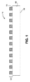
本発明の局面において、研磨パッドは、上に別個の突起を有する実質的に平らな均一な本体を提供される。例えば、図1は、本発明の実施形態に従って、上に別個の突起を有する均一な本体を有する研磨パッドの断面図を図示してる。 In aspects of the invention, the polishing pad is provided with a substantially flat uniform body having discrete protrusions thereon. For example, FIG. 1 illustrates a cross-sectional view of a polishing pad having a uniform body with separate protrusions thereon according to an embodiment of the present invention.
図1を参照すると、研磨パッド100は、基板を研磨するために提供される。研磨パッド100は、研磨面104と背面106とを有する均一な本体102を含む。均一な本体102は、第一の硬度を有する材料から成る。研磨パッド100は、均一な本体102の研磨面104に配置された複数の別個の突起108も含む。複数の別個の突起108は、第一の硬度とは異なる第二の硬度を有する材料から成る。実施形態において、図1に描写されているように、均一な本体102の研磨面104は、実質的に平らであり、均一な本体102の研磨面104は、複数の別個の突起108間で露出される。1つのそのような実施形態において、複数の別個の突起108の各々は、均一な本体102の研磨面104の全体の面において、約5〜50ミリメートルの範囲における最短の寸法を有する。
Referring to FIG. 1, a
本発明の実施形態に従って、均一な本体102の材料の硬度(第一の硬度)は、複数の別個の突起108の材料の硬度(第二の硬度)よりも低い。1つのそのような実施形態において、第一の硬度は、約40ショアDよりも低く、第二の硬度は、約30ショアDよりも高い。特定のそのような実施形態において、第一の硬度は、約25ショアDよりも低く、第二の硬度は、約40ショアDよりも高い。
According to an embodiment of the present invention, the material hardness (first hardness) of the
本発明の別の実施形態に従って、均一な本体102の材料の硬度(第一の硬度)は、複数の別個の突起108の材料の硬度(第二の硬度)よりも高い。1つのそのような実施形態において、第二の硬度は、約40ショアDよりも低く、第一の硬度は、約30ショアDよりも高い。特定のそのような実施形態において、第二の硬度は、約25ショアDよりも低く、第一の硬度は、約40ショアDよりも高い。
In accordance with another embodiment of the present invention, the material hardness (first hardness) of the
本発明の別の局面において、研磨パッドは、上に別個の突起を有する、表面的特徴のパターンを付けられた均一な本体を提供される。例えば、図2は、本発明の実施形態に従って、上に別個の突起を有する均一な本体を有する別の研磨パッドの断面図を図示している。 In another aspect of the invention, the polishing pad is provided with a uniform body patterned with surface features having discrete protrusions thereon. For example, FIG. 2 illustrates a cross-sectional view of another polishing pad having a uniform body with separate protrusions thereon according to an embodiment of the present invention.
図2を参照すると、研磨パッド200は、基板を研磨するために提供される。研磨パッド200は、研磨面204と背面206とを有する均一な本体202を含む。均一な本体202は、第一の硬度を有する材料から成る。均一な本体202の研磨面204は、パターンを有する複数の突起207を含む。研磨パッド200は、複数の別個の突起208も含み、複数の別個の突起208は、均一な本体202の研磨面204の複数の突起207上に配置され、かつ整列させられる。複数の別個の突起208は、複数の突起207のパターンを有し、複数の別個の突起208は、第一の硬度とは異なる第二の硬度を有する材料から成る。研磨パッド200は、均一な本体202の研磨面204の複数の突起207の周りにおいて、均一な本体202に配置された充填層210も含む。充填層は、複数の別個の突起208の材料から成る。1つのそのような実施形態において、複数の突起207の各々および複数の別個の突起208の各々は、均一な本体202の研磨面204の全体の面において、約5〜50ミリメートルの範囲における最短の寸法を有する。
Referring to FIG. 2, a
実施形態において、充填層210は、複数の別個の突起208と不連続である。つまり、図2を参照すると、充填層は、位置212において、複数の別個の突起208に結合されることも、複数の別個の突起208と連続であることもない。そのような配置は、研磨工程中に複数の別個の突起208の各々が均一な本体208へ圧縮されることの自由を可能にし得る。それにもかかわらず、不連続な充填層210の存在は、複数の別個の突起208の各々が均一な本体208に圧縮される場合に、複数の別個の突起208の各々の両側を誘導し、かつ支持し得る。しかしながら、代替実施形態において、充填層210は、複数の別個の突起208と連続である。
In an embodiment, the
本発明の実施形態に従って、均一な本体202の材料の硬度(第一の硬度)は、複数の別個の突起208および充填層210の材料の硬度(第二の硬度)よりも低い。1つのそのような実施形態において、第一の硬度は、約40ショアDよりも低く、第二の硬度は、約30ショアDよりも高い。特定のそのような実施形態において、第一の硬度は、約25ショアDよりも低く、第二の硬度は、約40ショアDよりも高い。
In accordance with an embodiment of the present invention, the hardness of the
本発明の別の実施形態に従って、均一な本体208の材料の硬度(第一の硬度)は、複数の別個の突起208および充填層210の材料の硬度(第二の硬度)よりも高い。1つのそのような実施形態において、第二の硬度は、約40ショアDよりも低く、第一の硬度は、約30ショアDよりも高い。特定のそのような実施形態において、第二の硬度は、約25ショアDよりも低く、第一の硬度は、約40ショアDよりも高い。
In accordance with another embodiment of the present invention, the material hardness (first hardness) of the
研磨パッド100および200内の異なる材料の部分は、互いに共有結合させられ得る。例えば、図1を参照すると、実施形態において、複数の別個の突起108は、均一な本体102の研磨面104に配置され、かつ均一な本体102の研磨面104と共有結合させられる。別の例において、図2を参照すると、実施形態において、充填層210と複数の別個の突起208との両方は、均一な本体202と共有結合させられる。特に、充填層210は、研磨面204のパターン内において共有結合させられる一方、複数の別個の突起208は、研磨面204のパターンの上部において共有結合させられる。
Portions of different materials within polishing
実施形態において、用語「共有結合」は、第一の材料(例えば、均一な本体102または202の材料)からの原子が、第二の材料(例えば、複数の別個の突起108または208の材料)からの原子と架橋結合させられるか、または電子を共有することにより、実際の化学結合をもたらす場合の配置を表す。そのような共有結合は、研磨パッドの一部が切り取られ、かつ異なる材料の挿入領域と取り替えられる場合に生じ得る静電相互作用と区別される。共有結合は、機械的結合(例えば、ねじ、くぎ、接着剤、または他の粘着性物質による結合)とも区別される。下記で詳細に説明されるように、共有結合は、研磨本体および複数の別個の突起を別々に形成することとは対照的に、研磨本体を複数の別個の突起と共に硬化させることによって達成され得る。
In embodiments, the term “covalent bond” refers to an atom from a first material (eg, a material of
研磨パッド100または200の材料は、成形され得る。例えば、図1を参照すると、実施形態において、均一な本体102は、成形された均一な本体であり、複数の別個の突起108は、複数の成形された突起である。別の例において、図2を参照すると、実施形態において、均一な本体208は、成形された均一な本体であり、複数の別個の突起208は、複数の成形された突起であり、充填層210は、成形された充填層である。
The material of the
用語「成形された」は、図7A〜7Gおよび8A〜8Dに関連して下記でより詳細に説明されるように、均一な本体および/または均一な本体上の別個の突起が、形成型において形成されることを示すために使用され得る。実施形態において、調整および/または研磨すると、成形された別個の突起は、約1〜5ミクロンの二乗平均の範囲における研磨表面粗さを有する。一実施形態において、調整および/または研磨すると、成形された別個の突起は、約2.35ミクロンの二乗平均の研磨表面粗さを有する。実施形態において、成形された別個の突起は、摂氏25度において、約30〜500メガパスカル(MPa)の範囲における貯蔵弾性率を有する。別の実施形態において、成形された別個の突起は、摂氏25度において、約30メガパスカル(MPa)よりも小さい貯蔵弾性率を有する。実施形態において、図7A〜7Gおよび8A〜8Dに関連して説明されるように、研磨パッドは、成形された研磨本体と成形された研磨本体上の成形された別個の突起とから成る。 The term “shaped” refers to a uniform body and / or separate protrusions on the uniform body in the forming mold, as described in more detail below in connection with FIGS. 7A-7G and 8A-8D. Can be used to indicate that it is formed. In embodiments, upon conditioning and / or polishing, the shaped discrete protrusions have a polishing surface roughness in the range of the root mean square of about 1-5 microns. In one embodiment, after conditioning and / or polishing, the shaped discrete protrusions have a root mean square surface roughness of about 2.35 microns. In embodiments, the molded discrete protrusion has a storage modulus in the range of about 30-500 megapascals (MPa) at 25 degrees Celsius. In another embodiment, the molded discrete protrusions have a storage modulus less than about 30 megapascals (MPa) at 25 degrees Celsius. In embodiments, as described in connection with FIGS. 7A-7G and 8A-8D, the polishing pad consists of a molded abrasive body and molded separate protrusions on the molded abrasive body.
研磨パッド100または200は、熱硬化性ポリウレタン材料から成る均一な本体を含み得る。実施形態において、均一な本体は、熱硬化性クローズドセルポリウレタン材料から成る。実施形態において、用語「均一な」は、熱硬化性クローズドセルポリウレタン材料の組成が、本体の全体の組成を通じて一貫していることを示すために使用される。例えば、実施形態において、用語「均一な」は、例えば、含浸フェルト、または異なる材料の複数の層の組成(合成物)から成る研磨パッド本体を除外する。
The
実施形態において、用語「熱硬化性」は、不可逆に硬化するポリマー材料(例えば、材料の前駆物質)が、硬化によって不溶解性の不溶性のポリマーネットワークに不可逆に変化することを示すために使用される。例えば、実施形態において、用語「熱硬化性」は、例えば、「熱可塑性」材料または「熱可塑性物質」から成る研磨パッドを除外し、これらの材料は、熱せられると液体になり、十分に冷やされると非常にガラスのような状態に戻るポリマーから成る。熱硬化性材料から作られる研磨パッドは、典型的に、化学反応において反応することによりポリマーを形成する低分子量の前駆物質から製作される一方、熱可塑性材料から作られるパッドは、典型的に、先在するポリマーを熱することにより相変化をもたらすことによって製作され、そのため、研磨パッドは、物理的工程において形成されることが、留意される。ポリウレタン熱硬化性ポリマーは、安定した熱および力学的特性、化学環境に対する耐性、および摩耗耐性に関する傾向に基づいて、本明細書中に説明される研磨パッドを製作するために選択され得る。 In embodiments, the term “thermoset” is used to indicate that a polymer material that irreversibly cures (eg, a precursor of the material) irreversibly changes to an insoluble, insoluble polymer network upon curing. The For example, in embodiments, the term “thermosetting” excludes polishing pads made of, for example, “thermoplastic” materials or “thermoplastics”, which become liquid when heated and are sufficiently cool. It is made of a polymer that returns to a very glassy state. Polishing pads made from thermoset materials are typically made from low molecular weight precursors that form polymers by reacting in chemical reactions, while pads made from thermoplastic materials are typically It is noted that the polishing pad is formed in a physical process, which is fabricated by inducing a phase change by heating an existing polymer. Polyurethane thermosetting polymers can be selected to fabricate the polishing pads described herein based on trends regarding stable thermal and mechanical properties, resistance to chemical environments, and abrasion resistance.
一実施形態において、図1を参照すると、均一な本体102の材料は、第一の熱硬化性ポリウレタン材料から成り、複数の別個の突起108の材料は、第二の異なる熱硬化性ポリウレタン材料から成る。一実施形態において、図2を参照すると、均一な本体202の材料は、第一の熱硬化性ポリウレタン材料から成り、複数の別個の突起208および充填層210の材料は、第二の異なる熱硬化性ポリウレタン材料から成る。
In one embodiment, referring to FIG. 1, the
実施形態において、本明細書中に説明される研磨パッド(例えば、研磨パッド100または200)は、中に複数のクローズドセルポアを有する研磨本体および/または研磨本体上の別個の突起を含む。一実施形態において、複数のクローズドセルポアは、複数のポロゲンである。例えば、用語「ポロゲン」は、「中空」の中心を有するマイクロまたはナノスケールの球形またはいくぶんか球形の粒子を示すために使用され得る。中空の中心は、固体材料で充填されず、むしろガスまたは液体のコアを含み得る。一実施形態において、複数のクローズドセルポアは、研磨パッドの研磨本体および/または別個の突起の至る所に(例えば、追加の構成要素として)分布させられた、事前発泡させたガス充填EXPANCELTMから成る。特定の実施形態において、EXPANCELTMは、ペンタンで充填される。実施形態において、複数のクローズドセルポアの各々は、約10〜100ミクロンの範囲における直径を有する。実施形態において、複数のクローズドセルポアは、互いから分離したポアを含む。これは、オープンセルポアと対照的であり、オープンセルポアは、一般的なスポンジにおけるポアの場合のように、トンネルを通して互いに接続され得る。一実施形態において、クローズドセルポアの各々は、上記で説明されたようなポロゲンの殻のような物理的殻を含む。しかしながら、別の実施形態において、クローズドセルポアの各々は、物理的殻を含まない。実施形態において、複数のクローズドセルポアは、均一な本体または均一な本体上に配置された均一な複数の別個の突起の熱硬化性ポリウレタン材料の至る所に、本質的に均等に分布させられる。
In embodiments, a polishing pad (eg, polishing
実施形態において、複数のクローズドセルポアの密度または濃度は、均一な本体(例えば、102または202)と複数の別個の突起(例えば、108または208)との間で異なる。1つのそのような実施形態において、均一な本体におけるクローズドセルの密度または濃度は、複数の別個の突起におけるクローズドセルの密度または濃度よりも低い。特定のそのような実施形態において、均一な本体にクローズドセルはない一方、複数の別個の突起にクローズドセルはある。代替実施形態において、均一な本体におけるクローズドセルの密度または濃度は、複数の別個の突起におけるクローズドセルの密度または濃度よりも高い。別の実施形態において、クローズドセルのタイプは、均一な本体と複数の別個の突起との間で異なる。 In embodiments, the density or concentration of the plurality of closed cell pores varies between a uniform body (eg, 102 or 202) and a plurality of discrete protrusions (eg, 108 or 208). In one such embodiment, the density or concentration of closed cells in the uniform body is lower than the density or concentration of closed cells in the plurality of separate protrusions. In certain such embodiments, there are no closed cells in the uniform body, while there are closed cells in multiple separate protrusions. In an alternative embodiment, the density or concentration of closed cells in the uniform body is higher than the density or concentration of closed cells in the plurality of separate protrusions. In another embodiment, the type of closed cell differs between the uniform body and the plurality of separate protrusions.
実施形態において、本明細書中に説明される研磨パッド(例えば、研磨パッド100または200)は、不透明な研磨本体および/または別個の突起を含む。一実施形態において、用語「不透明」は、約10%以下の可視光が通過することを可能にする材料を示すために使用される。一実施形態において、研磨本体および/または別個の突起は、研磨本体および/または別個の突起の至る所に(例えば、追加の構成要素として)不透明化粒子充填剤(例えば、潤滑剤)を含むことによって、大部分において、または完全に不透明である。特定の実施形態において、不透明化粒子充填剤は、窒化ホウ素、フッ化セリウム、黒鉛、フッ化黒鉛、硫化モリブデン、硫化ニオブ、タルク、硫化タンタル、二硫化タングステン、またはTeflon(登録商標)のような材料であるが、これらに制限されない。
In embodiments, a polishing pad (eg, polishing
実施形態において、不透明の程度または粒子充填剤の濃度は、均一な本体(例えば、102または202)と複数の別個の突起(例えば、108または208)との間で異なる。1つのそのような実施形態において、均一な本体における粒子充填剤の濃度は、複数の別個の突起における粒子充填剤の濃度よりも低い。特定のそのような実施形態において、均一な本体に含まれる粒子充填剤はない一方、粒子充填剤は、複数の別個の突起に含まれる。代替実施形態において、均一な本体における粒子充填剤の濃度は、複数の別個の突起における粒子充填剤の濃度よりも高い。別の実施形態において、粒子充填剤のタイプは、均一な本体と複数の別個の突起との間で異なる。 In embodiments, the degree of opacity or the concentration of particle filler varies between a uniform body (eg, 102 or 202) and a plurality of separate protrusions (eg, 108 or 208). In one such embodiment, the concentration of particle filler in the uniform body is lower than the concentration of particle filler in the plurality of separate protrusions. In certain such embodiments, no particle filler is included in the uniform body, while the particle filler is included in a plurality of separate protrusions. In an alternative embodiment, the concentration of particle filler in the uniform body is higher than the concentration of particle filler in the plurality of separate protrusions. In another embodiment, the type of particle filler is different between the uniform body and the plurality of separate protrusions.
本発明の局面において、複数の別個の突起108または208は、CMP動作中の研磨に適したパターンを有し得る。第一の一般的な例において、本発明のいくつかの実施形態は、タイルのパターンを有する複数の別個の突起を含む。特定のそのような実施形態において、図3は、本発明の実施形態に従って、上に別個の六角形のタイルの突起302を有する均一な本体を有する研磨パッド300の上から見下ろした図を図示している。他の特定のそのような実施形態は、複数の円形のタイル、楕円形のタイル、正方形のタイル、長方形のタイル、またはそれらの組み合わせを含むが、これらに制限されない。
In aspects of the invention, the plurality of
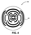
第二の一般的な例において、本発明のいくつかの実施形態は、曲がった特徴のパターンを有する複数の別個の突起を含む。特定のそのような例において、図4は、本発明の実施形態に従って、上に別個の弓型の突起402を有する均一な本体を有する研磨パッド400の上から見下ろした図を図示している。他の特定のそのような実施形態は、研磨パッドの実質的に円形の均一な本体に配置された複数の部分的な円周の突起を含むが、これに制限されない。
In a second general example, some embodiments of the invention include a plurality of separate protrusions having a pattern of curved features. In certain such examples, FIG. 4 illustrates a top down view of a
第三の一般的な例において、本発明のいくつかの実施形態は、線形の特徴のパターンを有する複数の別個の突起を含む。特定のそのような例において、図5は、本発明の実施形態に従って、上に別個の線形の区分の突起502を有する均一な本体を有する研磨パッド500の上から見下ろした図を図示している。示されている別個の線形の区分の突起は、研磨表面の半径に本質的に直交する。しかしながら、本発明の実施形態は、研磨表面の半径に正確には直交しない別個の線形の区分も含み得ることが理解される。そのような実施形態において、別個の線形の区分は、同心またはほぼ同心の多角形配置の一部を形成し得るが、完全な同心またはほぼ同心の多角形配置は形成しない。対応する半径との相対的な関係は、正確に90度ではなく、むしろ、ことによると、90度から数度離れる方へのわずかな程度である。それにもかかわらず、そのような直交に近いまたはほぼ直交する別個の線形の区分は、本発明の精神および範囲の範囲内にあるとみなされる。
In a third general example, some embodiments of the present invention include a plurality of separate protrusions having a pattern of linear features. In certain such examples, FIG. 5 illustrates a top down view of a
実施形態において、本明細書中に説明される研磨パッド(例えば、研磨パッド100、200、300、400、または500)は、基板を研磨することに適している。基板は、半導体製造産業において使用されるもの(例えば、デバイスまたは他の層が上に配置されるシリコン基板)であり得る。しかしながら、基板は、MEMSデバイス、レチクル、またはソーラーモジュールのための基板のようなものであり得るが、これらに制限されない。従って、本明細書中に使用されるような「基板を研磨する研磨パッド」への参照は、これらおよび関連した可能性を包含することが意図される。
In embodiments, the polishing pad described herein (eg, polishing
均一な本体および均一な本体に配置された別個の突起のサイジングは、用途に従って変えられ得る。それにもかかわらず、特定のパラメータは、別個の突起が上に配置されたそのような均一な本体を含む研磨パッドを、従来の処理設備、または従来の化学機械処理動作とさえ適合可能にするために使用され得る。例えば、本発明の実施形態に従って、均一な本体と均一な本体に配置された別個の突起との組み合わせは、約0.075インチ〜0.130インチの範囲(例えば、約1.9〜3.3ミリメートルの範囲)における厚さを有する。一実施形態において、均一な本体は、約20インチ〜30.3インチの範囲(例えば、約50〜77センチメートルの範囲)、および、ことによると、約10インチ〜42インチの範囲(例えば、約25〜107センチメートルの範囲)における直径を有する。一実施形態において、均一な本体および/または均一な本体に配置された別個の突起は、約6%〜36%総空隙体積の範囲、および、ことによると、約15%〜35%総空隙体積の範囲におけるポア密度を有する。一実施形態において、均一な本体と均一な本体に配置された別個の突起との組み合わせは、約2.5%の圧縮率を有する。一実施形態において、均一な本体は、約0.70〜1.05グラム毎立法センチメートルの範囲における密度を有する。 The sizing of the uniform body and the separate protrusions disposed on the uniform body can be varied according to the application. Nonetheless, certain parameters are required to make a polishing pad comprising such a uniform body with a separate protrusion disposed thereon compatible with conventional processing equipment, or even conventional chemical mechanical processing operations. Can be used. For example, in accordance with embodiments of the present invention, the combination of a uniform body and separate protrusions disposed on the uniform body can range from about 0.075 inches to 0.130 inches (eg, about 1.9-3. Thickness in the range of 3 millimeters). In one embodiment, the uniform body has a range of about 20 inches to 30.3 inches (eg, a range of about 50 to 77 centimeters), and possibly a range of about 10 inches to 42 inches (eg, Having a diameter in the range of about 25-107 centimeters). In one embodiment, the uniform body and / or separate protrusions disposed on the uniform body may range from about 6% to 36% total void volume, and possibly about 15% to 35% total void volume. Having a pore density in the range of In one embodiment, the combination of the uniform body and the separate protrusions disposed on the uniform body has a compression rate of about 2.5%. In one embodiment, the uniform body has a density in the range of about 0.70 to 1.05 grams per cubic centimeter.
本発明の別の局面において、上に別個の突起を有する均一な本体を有する研磨パッドは、例えば渦電流検出システムを用いた使用のための検出領域をさらに含む。例えば、図6は、本発明の実施形態に従って、上に別個の突起を有し、かつ局所透明(local area transparency、LAT)領域および/または表示領域を含む均一な本体を有する研磨パッド600の上から見下ろした平面図を図示している。
In another aspect of the present invention, a polishing pad having a uniform body with discrete protrusions thereon further includes a detection region for use with, for example, an eddy current detection system. For example, FIG. 6 illustrates a top view of a
図6を参照すると、研磨パッド600の研磨表面602は、研磨パッド600の背表面に配置された検出領域の位置を示す表示領域604を含む。一実施形態において、表示領域604は、図6に描写されているように、突起606のパターンを突起608の第二のパターンで分断する。適した検出領域(例えば渦電流検出領域)の例は、米国特許出願第12/895,465号(2010年9月30日出願、NexPlanar Corporationに譲渡)において説明されている。
Referring to FIG. 6, the polishing
別の局面において、上に別個の突起を有する均一な本体を有する研磨パッドは、研磨パッドに配置された局所透明(LAT)領域をさらに含む。例えば、再び図6を参照すると、LAT領域610は、研磨パッド600の研磨本体に配置される。図6に描写されているように、LAT領域604は、突起606のパターンを分断する。実施形態において、LAT領域610は、研磨パッド600の均一な本体に配置され、かつ研磨パッド600の均一な本体と共有結合させられる。適したLAT領域の例は、米国特許出願第12/895,465号(2010年9月30日出願、NexPlanar Corporationに譲渡)において説明されている。
In another aspect, a polishing pad having a uniform body with discrete protrusions thereon further includes a locally transparent (LAT) region disposed on the polishing pad. For example, referring again to FIG. 6, the
本発明の別の局面において、複数の別個の突起が上に配置された均一な本体を有する研磨パッドは、成形工程において製作され得る。第一のそのような例において、図7A〜7Gは、本発明の実施形態に従って、上に別個の突起を有する均一な本体を有する研磨パッドの製作において使用される動作の断面図を図示している。 In another aspect of the present invention, a polishing pad having a uniform body with a plurality of discrete protrusions disposed thereon can be fabricated in a molding process. In a first such example, FIGS. 7A-7G illustrate cross-sectional views of operations used in the fabrication of a polishing pad having a uniform body with separate protrusions thereon, in accordance with an embodiment of the present invention. Yes.
図7Aを参照すると、形成型700が、提供される。図7Bを参照すると、プレポリマー702および硬化剤704が、混合されることにより、図7Cに描写されているように、形成型700に第一の混合物706を形成する。実施形態において、プレポリマー702と硬化剤704とを混合することは、イソシアネートと芳香族ジアミン化合物とをそれぞれ混合することを含む。一実施形態において、混合することは、研磨パッドの不透明な成形された均一な本体を最終的に提供するために、不透明化粒子充填剤をプレポリマー702および硬化剤704に追加することをさらに含む。特定の実施形態において、不透明化粒子充填剤は、窒化ホウ素、フッ化セリウム、黒鉛、フッ化黒鉛、硫化モリブデン、硫化ニオブ、タルク、硫化タンタル、二硫化タングステン、またはTeflonのような材料であるが、これらに制限されない。
Referring to FIG. 7A, a forming
実施形態において、第一の混合物706は、熱硬化性クローズドセルポリウレタン材料から成る成形された均一な本体を最終的に形成するために使用される。一実施形態において、第一の混合物706は、硬い均一な本体を最終的に形成するために使用され、単一のタイプの硬化剤のみが使用される。別の実施形態において、第一の混合物706は、軟らかい均一な本体を最終的に形成するために使用され、第一次および第二次硬化剤の組み合わせが使用される。例えば、特定の実施形態において、プレポリマーは、ポリウレタン前駆物質を含み、第一次硬化剤は、芳香族ジアミン化合物を含み、第二次硬化剤は、エーテル結合を有する化合物を含む。特定の実施形態において、ポリウレタン前駆物質は、イソシアネートであり、第一次硬化剤は、芳香族ジアミンであり、第二次硬化剤は、ポリテトラメチレングリコール、アミノ官能基化(amino−functionalized)グリコール、またはアミノ官能基化ポリオキシプロピレンのような硬化剤であるが、これらに制限されない。実施形態において、プレポリマー、第一次硬化剤、および第二次硬化剤は、プレポリマー100、第一次硬化剤85、第二次硬化剤15の割合のおおよそのモル比を有する。比の変化は、硬度値を変えて均一な本体を提供するため、またはプレポリマーならびに第一および第二の硬化剤の特定の性質に基づいて均一な本体を提供するために使用され得ることが、理解される。
In an embodiment, the
図7Dを参照すると、混合物706は、少なくとも部分的に硬化させられることにより、研磨面710と背面712とを有する成形された均一な本体708を形成する。部分的な硬化は、形成型のふたがある場合またはない場合に、型700を熱することによって実施され得る。それから、第二のプレポリマーおよび第二の硬化剤が、混合されることにより、図7Eに描写されているように、成形された均一な本体708上に第二の混合物714を形成する。実施形態において、第二の混合物714は、硬い材料を形成するためのものであり、単一の硬化剤と一緒にプレポリマーが使用される(2タンク工程)一方、第一の混合物706は、軟らかい材料を形成するためのものであり、第一次硬化剤および第二次硬化剤と一緒にプレポリマーが使用される(3タンク工程)。代替実施形態において、第一の混合物706は、硬い材料を形成するためのものであり、単一の硬化剤と一緒にプレポリマーが使用される(2タンク工程)一方、第二の混合物714は、軟らかい材料を形成するためのものであり、第一次硬化剤および第二次硬化剤と一緒にプレポリマーが使用される(3タンク工程)。従って、実施形態において、第二の混合物714は、第一の混合物706とは異なる。しかしながら、代替実施形態において、2つの混合物は、同じである。さらに、実施形態において、第二の混合物は、部分的に、または完全に硬化させられた第一の混合物706上に配置される。しかしながら、代替実施形態において、第二の混合物714を注ぐことまたは分配することは、同じ層であるが異なる領域において、加えられた第一の混合物706にその場で注がれ得る。特定のそのような実施形態において、中心の輪および外側の輪は、異なる調合物を有する。2つの異なった層が形成される実施形態において、層間の化学結合を強くするために、異なる層内の官能基の比は、異なる(例えば、1つの層は、−NCOが豊富であり、他の層は、−NH2および/または−OHが豊富である)。実施形態において、コーティングが、異なる層間に塗布される。実施形態において、浸透が、層間で発生し、浸透は、共有結合のような化学結合を強くする。
Referring to FIG. 7D, the
実施形態において、第二のプレポリマーと第二の硬化剤とを混合することは、不透明な複数の別個の突起718を形成するために、不透明化粒子充填剤を第二のプレポリマーおよび第二の硬化剤に追加することをさらに含む。実施形態において、第一のプレポリマーと第一の硬化剤とを混合することにより第一の混合物706を形成することは、第一の混合物706からガスを抜くことを含み、第二のプレポリマーと第二の硬化剤とを混合することにより第二の混合物714を形成することは、第二の混合物714からガスを抜くことを含む。
In an embodiment, mixing the second prepolymer and the second curing agent may cause the opacifying particle filler to form the second prepolymer and the second to form a plurality of opaque
図7Fを参照すると、形成型700のふた716が、第二の混合物714内に配置される。図7Fにおいて、ふた716の上から見下ろした平面図が、上に示されている一方、a−a’軸に沿った断面が、下に示されている。ふた716は、図7Fに描写されているように、ふたに配置された溝のパターン(例えば、図3に関連して説明された突起のパターンに対応する溝のパターン)を有する。しかしながら、あるいは、ふたは716は、ふたに配置された、図4および5に関連して説明された突起のパターンに対応する溝のパターンを有する。
Referring to FIG. 7F, the
形成型700のふた716を降下させることを説明する本明細書中に説明された実施形態は、形成型700のふた716およびベースを一緒にすることを達成することのみが必要であることが理解される。つまり、いくつかの実施形態において、形成型700のベースが、ふた716の方へ上昇させられる一方、他の実施形態において、ベースがふた716の方へ上昇させられるのと同時に、形成型700のふた716が、形成型700のベースの方へ降下させられる。
It will be understood that the embodiments described herein that describe lowering the
ふた716が第二の混合物714に配置された状態で、第二の混合物714は、少なくとも部分的に硬化させられることにより、成形された均一な本体708の研磨面710に配置された複数の別個の突起718を形成する。ふた716の溝のパターンは、形成型700において第二の混合物714から突起のパターンを打ち出すために使用される。第二の混合物714は、(例えば、ふた716が定位置にある状態で)圧力下で熱されることにより、成形された別個の突起718を提供し得る。実施形態において、形成型700において熱することは、ふた716がある場合に少なくとも部分的に硬化させることを含み、ふた716は、華氏約200〜260度の範囲における温度、および約2〜12ポンド毎平方インチの範囲における圧力において、形成型700に第二の混合物714を閉じ込める。
With the
実施形態において、第二の混合物714は、第一の混合物706とは異なり、第一の混合物706および第二の混合物714を完全に硬化させると、複数の別個の突起718の硬度は、成形された均一な本体708の硬度とは異なる。実施形態において、第二の混合物714を少なくとも部分的に硬化させることは、複数の別個の突起718を成形された均一な本体708と共有結合させることを含む。実施形態において、成形された均一な本体708を形成することは、第一の熱硬化性ポリウレタン材料を形成することを含み、複数の別個の突起718を形成することは、第二の異なる熱硬化性ポリウレタン材料を形成することを含む。
In an embodiment, the
図7Gを参照すると、研磨パッド720は、複数の別個の突起718が上に配置された成形された均一な本体708を形成型700から取り外すと、提供される。複数の別個の突起718は、ふた716の溝のパターンに対応するパターンを有する。図7Gにおいて、研磨パッド720の上から見下ろした平面図が、下に示されている一方、b−b’軸に沿った断面が、上に示されている。実施形態において、図7Gの断面図において描写されているように、成形された均一な本体708の研磨面710は、実質的に平らであり、成形された均一な本体708の研磨面710は、複数の別個の突起718間で露出される。
Referring to FIG. 7G, the
熱することによってさらに硬化させることは、望ましくあり得、かつ研磨パッド720をオーブンに配置して熱することによって実施され得ることが、留意される。従って、一実施形態において、第一および第二の混合物706および714を硬化させることは、初めに形成型700において部分的に硬化させて、それからオーブンにおいてさらに硬化させることを含む。どちらにしろ、研磨パッド720が最終的に提供され、研磨パッド720の成形された均一な本体708は、複数の成形された突起718が上に配置された研磨面710を有する。実施形態において、成形された均一な本体708と複数の成形された突起718との両方は、熱硬化性ポリウレタン材料、および熱硬化性ポリウレタン材料に配置された複数のクローズドセルポアから成る。
It is noted that further curing by heating may be desirable and may be performed by placing the
図7A〜7Gに関連して説明された方法と同様の方法は、上に別個の突起を有する、表面的特徴のパターンを付けられた均一な本体を有する研磨パッドを製作するために使用され得る。例えば、図8A〜8Dは、本発明の実施形態に従って、上に別個の突起を有する均一な本体を有する別の研磨パッドの製作において使用される動作の断面図を図示している。 A method similar to that described in connection with FIGS. 7A-7G may be used to fabricate a polishing pad having a uniform body patterned with surface features, with separate protrusions thereon. . For example, FIGS. 8A-8D illustrate cross-sectional views of operations used in the fabrication of another polishing pad having a uniform body with separate protrusions thereon, in accordance with an embodiment of the present invention.
再び図7Cを参照し、次に図8Aを参照すると、第一の混合物706を硬化させることにより実質的に平らな表面を均一な本体708に提供することの代わりに、(図7Fに関連して説明された)ふた716が、研磨面802を有する成形された均一な本体800を最初に形成するために使用され、研磨面802は、ふた716の溝のパターンに対応するパターンを有する複数の突起804を有する。例えば、第一のプレポリマーと第一の硬化剤とを混合することにより第一の混合物706を形成することの次であるが、第二のプレポリマーと第二の硬化剤とを混合することにより第二の混合物714を形成することの前に、形成型700のふた716が、第一の混合物706内へ配置される。ふたが第一の混合物706に配置された状態で、第一の混合物706は、図8Bに描写されているように、少なくとも部分的に硬化させられる。
Referring again to FIG. 7C and then to FIG. 8A, instead of providing a substantially flat surface to the
図8Cを参照すると、それから、第二のプレポリマーと第二の硬化剤は、混合されることにより、成形された均一な本体800上に第二の混合物714を形成する。それから、形成型700のふた716は、図8Dに描写されているように、第二の混合物714内に配置される。ふた716が第二の混合物714に配置された状態で、第二の混合物714は、少なくとも部分的に硬化させられることにより、複数の別個の突起718を形成し、複数の別個の突起718は、成形された均一な本体800の研磨面802の複数の突起804上に配置され、かつ整列させられる。ふた716の溝のパターンは、形成型700において第二の混合物714から突起のパターンを打ち出すために使用される。それから、第二の混合物714は、(例えば、ふた716が定位置にある状態で)圧力下で熱されることにより、成形された別個の突起718を提供し得る。実施形態において、形成型700において熱することは、ふた716がある場合に少なくとも部分的に硬化させることを含み、ふた716は、華氏約200〜260度の範囲における温度、および約2〜12ポンド毎平方インチの範囲における圧力において、形成型700に第二の混合物714を閉じ込める。図2に関連して説明された研磨パッド200のような研磨パッドは、このように形成され得る。
Referring to FIG. 8C, the second prepolymer and the second curing agent are then mixed to form a
再び図8Dを参照すると、実施形態において、成形された均一な本体800上に第二の混合物714を形成することは、成形された均一な本体800の研磨面802の複数の突起804の周りにおいて、成形された均一な本体800に配置された充填層806を形成するほど十分に大きい量の第二の混合物714を形成することを含む。1つのそのような実施形態において、第二の混合物714の量は、第二の混合物714から形成された複数の別個の突起718と不連続である充填層806を形成するほど十分に小さい。そのような不連続の例は、図2の研磨パッド200に関連して上記で説明されている。実施形態において、スピンプレートが、成形された均一な本体800の研磨面802に分配された第二の混合物714の量および厚さを制御するために使用される。
Referring again to FIG. 8D, in an embodiment, forming the
実施形態において、複数の別個の突起718は、成形された均一な本体800の研磨面802の複数の突起804上に形成され、かつ整列させられる。整列は、わずかな誤った整列を許容し得る。例えば、約1/1000インチまでの範囲におけるずれは、第一の混合物706および第二の混合物714それぞれへのふた716の別々の導入の間に許容可能であり得る。
In an embodiment, a plurality of
実施形態において、図7Bを再び参照すると、混合することは、複数のポロゲン722をプレポリマー702および硬化剤704に追加することにより、研磨パッドの最終的に形成された本体にクローズドセルポアを提供することをさらに含む。従って、一実施形態において、各クローズドセルポアは、物理的殻を有する。別の実施形態において、図7Bを再び参照すると、混合することは、プレポリマー702および硬化剤704内へ、またはプレポリマー702および硬化剤704から形成された生成物内へガス724を注入することにより、研磨パッドの最終的に形成された本体にクローズドセルポアを提供することをさらに含む。従って、一実施形態において、各クローズドセルポアは、物理的殻を有しない。組み合わせの実施形態において、混合することは、複数のポロゲン722をプレポリマー702および硬化剤704に追加することにより、各々が物理的殻を有するクローズドセルポアの第一の部分を提供することと、さらに、プレポリマー702および硬化剤704内へ、またはプレポリマー702および硬化剤704から形成された生成物内へガス724を注入することにより、各々が物理的殻を有しないクローズドセルポアの第二の部分を提供することとを含む。さらに別の実施形態において、プレポリマー702は、イソシアネートであり、混合することは、プレポリマー702および硬化剤704に水(H2O)を追加することにより、各々が物理的殻を有しないクローズドセルポアを提供することをさらに含む。実施形態において、図7Eおよび8Cを参照すると、複数のポロゲンは、成形された別個の複数の突起718に同様に含まれ得る。
In an embodiment, referring again to FIG. 7B, mixing provides a closed cell pore in the final formed body of the polishing pad by adding a plurality of
従って、本発明の実施形態において想定される突起パターンは、その場で形成され得る。例えば、上記で説明されたように、圧縮成型工程は、成形された別個の突起が上に配置された成形された均一な本体を有する研磨パッドを形成するために使用され得る。成型工程を使用することによって、パッド内の非常に一様な突起寸法が、達成され得る。さらに、非常に滑らかなきれいな突起表面に加えて、極度に再現可能な突起寸法が、生成され得る。他の利点は、減少させられた欠陥および微小なひっかき傷、ならびにより大きな使用可能な突起深さを含み得る。 Therefore, the projection pattern assumed in the embodiment of the present invention can be formed in situ. For example, as described above, a compression molding process can be used to form a polishing pad having a molded uniform body with a molded discrete protrusion disposed thereon. By using a molding process, very uniform protrusion dimensions within the pad can be achieved. Furthermore, in addition to a very smooth clean projection surface, extremely reproducible projection dimensions can be generated. Other advantages may include reduced defects and micro-scratches, and a larger usable protrusion depth.
本明細書中に説明された研磨パッドは、種々の化学機械研磨装置を用いた使用に適し得る。例として、図9は、本発明の実施形態に従って、上に別個の突起を有する均一な本体を有する研磨パッドと適合可能な研磨装置の等角投影図法による側面からの図を図示している。 The polishing pads described herein may be suitable for use with a variety of chemical mechanical polishing equipment. As an example, FIG. 9 illustrates an isometric view of a polishing apparatus that is compatible with a polishing pad having a uniform body with separate protrusions thereon, in accordance with an embodiment of the present invention.
図9を参照すると、研磨装置900は、プラテン904を含む。プラテン904の上部表面902は、上に別個の突起を有する均一な本体を有する研磨パッドを支持するために使用され得る。プラテン904は、スピンドルの回転906およびスライダーの振動908を提供するように構成され得る。サンプルキャリアー910は、例えば、研磨パッドを用いた半導体ウェーハの研磨中に定位置に半導体ウェーハ911を保持するために使用される。サンプルキャリアー910は、サスペンションメカニズム912によってさらに支持される。スラリーフィード914は、半導体ウェーハの研磨の前および研磨中に、スラリーを研磨パッドの表面に提供するために含まれる。調整ユニット990も含まれ得、一実施形態において、調整ユニット990は、研磨パッドを調整するためにダイヤモンドチップを含む。
Referring to FIG. 9, the polishing
このように、上に別個の突起を有する均一な本体を有する研磨パッドが、開示された。本発明の実施形態に従って、基板を研磨する研磨パッドは、研磨面と背面とを有する均一な本体を含む。均一な本体は、第一の硬度を有する材料から成る。複数の別個の突起は、均一な本体の研磨面に配置され、かつ均一な本体の研磨面と共有結合させられる。複数の別個の突起は、第一の硬度とは異なる第二の硬度を有する材料から成る。一実施形態において、均一な本体の研磨面は、実質的に平らであり、均一な本体の研磨面は、複数の別個の突起間で露出される。一実施形態において、充填層は、均一な本体の研磨面の複数の突起の周りにおいて、均一な本体に配置され、充填層は、複数の別個の突起の材料から成る。一実施形態において、均一な本体は、成形された均一な本体であり、複数の別個の突起は、複数の成形された突起である。
1つの好ましい実施形態によれば、本発明は、例えば、以下を提供する。
(項1)
基板を研磨する研磨パッドであって、該研磨パッドは、
研磨面と背面とを有する均一な本体であって、該均一な本体は、第一の硬度を有する材料を含む、均一な本体と、
該均一な本体の該研磨面に配置され、かつ該均一な本体の該研磨面と共有結合させられた複数の別個の突起であって、該複数の別個の突起は、該第一の硬度とは異なる第二の硬度を有する材料を含む、複数の別個の突起と
を含む、研磨パッド。
(項2)
前記均一な本体の前記研磨面は、実質的に平らであり、該均一な本体の該研磨面は、前記複数の別個の突起間で露出されている、上記項1に記載の研磨パッド。
(項3)
前記均一な本体は、成形された均一な本体であり、前記複数の別個の突起は、複数の成形された突起である、上記項1に記載の研磨パッド。
(項4)
前記均一な本体の前記材料は、第一の熱硬化性ポリウレタン材料を含み、前記複数の別個の突起の前記材料は、第二の異なる熱硬化性ポリウレタン材料を含む、上記項1に記載の研磨パッド。
(項5)
前記均一な本体の前記材料の前記第一の硬度は、前記複数の別個の突起の前記材料の前記第二の硬度よりも低い、上記項1に記載の研磨パッド。
(項6)
前記第一の硬度は、約40ショアDよりも低く、前記第二の硬度は、約30ショアDよりも高い、上記項5に記載の研磨パッド。
(項7)
前記第一の硬度は、約25ショアDよりも低く、前記第二の硬度は、約40ショアDよりも高い、上記項6に記載の研磨パッド。
(項8)
前記均一な本体の前記材料の前記第一の硬度は、前記複数の別個の突起の前記材料の前記第二の硬度よりも高い、上記項1に記載の研磨パッド。
(項9)
前記第二の硬度は、約40ショアDよりも低く、前記第一の硬度は、約30ショアDよりも高い、上記項8に記載の研磨パッド。
(項10)
前記第二の硬度は、約25ショアDよりも低く、前記第一の硬度は、約40ショアDよりも高い、上記項9に記載の研磨パッド。
(項11)
前記均一な本体は、実質的に円形であり、前記複数の別個の突起のうちの1つ以上は、部分的な円周の突起または弓型の突起である、上記項1に記載の研磨パッド。
(項12)
前記複数の別個の突起は、円形のタイル、楕円形のタイル、正方形のタイル、六角形のタイル、および長方形のタイルから成る群から選択される複数のタイルを含む、上記項1に記載の研磨パッド。
(項13)
前記均一な本体の前記研磨面の全体の面において、前記複数の別個の突起の各々は、約5〜50ミリメートルの範囲における最短の寸法を有する、上記項1に記載の研磨パッド。
(項14)
前記均一な本体の前記背面に配置された検出領域をさらに含む、上記項1に記載の研磨
パッド。
(項15)
前記均一な本体に配置された局所透明(local area transparency、LAT)領域をさらに含む、上記項1に記載の研磨パッド。
(項16)
基板を研磨する研磨パッドであって、該研磨パッドは、
研磨面と背面とを有する均一な本体であって、該均一な本体は、第一の硬度を有する材料を含み、該研磨面は、パターンを有する複数の突起を含む、均一な本体と、
該均一な本体の該研磨面の該複数の突起上に配置され、かつ整列させられた複数の別個の突起であって、該複数の別個の突起は、該第一の硬度とは異なる第二の硬度を有する材料を含み、該複数の別個の突起は、該パターンを有する、複数の別個の突起と、
該均一な本体の該研磨面の該複数の突起の周りにおいて、該均一な本体に配置された充填層であって、該充填層は、該複数の別個の突起の該材料を含む、充填層と
を含む、研磨パッド。
(項17)
前記充填層は、前記複数の別個の突起と不連続である、上記項16に記載の研磨パッド。
(項18)
前記充填層と前記複数の別個の突起との両方は、前記均一な本体と共有結合させられている、上記項16に記載の研磨パッド。
(項19)
前記均一な本体は、成形された均一な本体であり、前記複数の別個の突起は、複数の成形された突起であり、前記充填層は、成形された充填層である、上記項16に記載の研磨パッド。
(項20)
前記均一な本体の前記材料は、第一の熱硬化性ポリウレタン材料を含み、前記複数の別個の突起および前記充填層の前記材料は、第二の異なる熱硬化性ポリウレタン材料を含む、上記項16に記載の研磨パッド。
(項21)
前記均一な本体の前記材料の前記第一の硬度は、前記複数の別個の突起および前記充填層の前記材料の前記第二の硬度よりも低い、上記項16に記載の研磨パッド。
(項22)
前記第一の硬度は、約40ショアDよりも低く、前記第二の硬度は、約30ショアDよりも高い、上記項21に記載の研磨パッド。
(項23)
前記第一の硬度は、約25ショアDよりも低く、前記第二の硬度は、約40ショアDよりも高い、上記項22に記載の研磨パッド。
(項24)
前記均一な本体の前記材料の前記第一の硬度は、前記複数の別個の突起および前記充填層の前記材料の前記第二の硬度よりも高い、上記項16に記載の研磨パッド。
(項25)
前記第二の硬度は、約40ショアDよりも低く、前記第一の硬度は、約30ショアDよりも高い、上記項24に記載の研磨パッド。
(項26)
前記第二の硬度は、約25ショアDよりも低く、前記第一の硬度は、約40ショアDよりも高い、上記項25に記載の研磨パッド。
(項27)
前記均一な本体は、実質的に円形であり、前記複数の別個の突起のうちの1つ以上は、部分的な円周の突起または弓型の突起である、上記項16に記載の研磨パッド。
(項28)
前記複数の別個の突起は、円形のタイル、楕円形のタイル、正方形のタイル、六角形のタイル、および長方形のタイルから成る群から選択される複数のタイルを含む、上記項16に記載の研磨パッド。
(項29)
前記均一な本体の前記研磨面の全体の面において、前記複数の別個の突起の各々は、約5〜50ミリメートルの範囲における最短の寸法を有する、上記項16に記載の研磨パッド。
(項30)
前記均一な本体の前記背面に配置された検出領域をさらに含む、上記項16に記載の研磨パッド。
(項31)
前記均一な本体に配置された局所透明(local area transparency、LAT)領域をさらに含む、上記項16に記載の研磨パッド。
(項32)
基板を研磨する研磨パッドを製作する方法であって、該方法は、
重合可能な材料の第一の組を混合することにより形成型のベースにおいて第一の混合物を形成することと、
該第一の混合物を少なくとも部分的に硬化させることにより研磨面と背面とを有する成形された均一な本体を形成することと、
重合可能な材料の第二の組を混合することにより該成形された均一な本体の上に第二の混合物を形成することと、
該形成型のふたを該第二の混合物内へ配置することであって、該ふたは、該ふたに配置された溝のパターンを有する、ことと、
該ふたが該第二の混合物に配置された状態で、該第二の混合物を少なくとも部分的に硬化させることにより該成形された均一な本体の該研磨面に配置された複数の別個の突起を形成することであって、該複数の別個の突起は、該ふたの該溝のパターンに対応するパターンを有する、ことと
を含む、方法。
(項33)
前記重合可能な材料の第一の組を混合することにより前記第一の混合物を形成することの次であるが、前記重合可能な材料第二の組を混合することにより前記第二の混合物を形成することの前に、前記形成型の前記ふたを該第一の混合物内へ配置することと、該ふたが該第一の混合物に配置された状態で、該第一の混合物を少なくとも部分的に硬化させることを実施することにより前記研磨面を有する前記成形された均一な本体を形成することとをさらに含み、該研磨面は、該ふたの前記溝のパターンに対応するパターンを有する複数の突起を含み、前記複数の別個の突起は、該成形された均一な本体の該研磨面の該複数の突起上に形成され、かつ整列させられている、上記項32に記載の方法。
(項34)
前記成形された均一な本体の上に前記第二の混合物を形成することは、該成形された均一な本体の前記研磨面の前記複数の突起の周りにおいて、該成形された均一な本体に配置された充填層を形成するほど十分に大きい量の前記第二の混合物を形成することを含み、該第二の混合物の該量は、該第二の混合物から形成された前記複数の別個の突起と不連続である該充填層を形成するほど十分に小さい、上記項33に記載の方法。
(項35)
前記重合可能な材料の第一の組は、第一のプレポリマーと第一の硬化剤とを含み、前記重合可能な材料の第二の組は、第二のプレポリマーと第二の硬化剤とを含む、上記項32に記載の方法。
(項36)
前記成形された均一な本体の前記研磨面は、実質的に平らであり、該成形された均一な本体の該研磨面は、前記複数の別個の突起間で露出されている、上記項32に記載の方法。
(項37)
前記第二の混合物は、前記第一の混合物とは異なり、該第一および第二の混合物を完全に硬化させると、前記複数の別個の突起の硬度は、前記成形された均一な本体の硬度とは異なる、上記項32に記載の方法。
(項38)
前記第二の混合物を少なくとも部分的に硬化させることは、前記複数の別個の突起を前記成形された均一な本体と共有結合させることを含む、上記項32に記載の方法。
(項39)
前記成形された均一な本体を形成することは、第一の熱硬化性ポリウレタン材料を形成することを含み、前記複数の別個の突起を形成することは、第二の異なる熱硬化性ポリウレタン材料を形成することを含む、上記項32に記載の方法。
(項40)
前記重合可能な材料の第二の組の前記混合は、複数のポロゲンを該重合可能な材料の第二の組に追加することにより前記複数の別個の突起における複数のクローズドセルポアを形成することをさらに含み、各クローズドセルポアは物理的殻を有する、上記項32に記載の方法。
(項41)
前記重合可能な材料の第二の組の前記混合は、該重合可能な材料の第二の組内へ、または該重合可能な材料の第二の組から形成された生成物内へガスを注入することにより前記複数の別個の突起における複数のクローズドセルポアを形成することをさらに含み、各クローズドセルポアは、物理的殻を有しない、上記項32に記載の方法。
(項42)
前記重合可能な材料の第二の組の前記混合は、不透明化粒子充填剤を該重合可能な材料の第二の組に追加することにより不透明な複数の別個の突起を形成することをさらに含む、上記項32に記載の方法。
(項43)
オーブンにおいて前記複数の別個の突起および前記成形された均一な本体をさらに硬化させることをさらに含む、上記項32に記載の方法。
(項44)
前記第一のプレポリマーと第一の硬化剤とを混合することにより前記第一の混合物を形成することは、該第一の混合物からガスを抜くことを含み、前記第二のプレポリマーと前記第二の硬化剤とを混合することにより前記第二の混合物を形成することは、該第二の混合物からガスを抜くことを含む、上記項35に記載の方法。
Thus, a polishing pad having a uniform body with discrete protrusions thereon has been disclosed. In accordance with an embodiment of the present invention, a polishing pad for polishing a substrate includes a uniform body having a polishing surface and a back surface. The uniform body is made of a material having a first hardness. A plurality of separate protrusions are disposed on the uniform body polishing surface and are covalently bonded to the uniform body polishing surface. The plurality of separate protrusions are made of a material having a second hardness different from the first hardness. In one embodiment, the uniform body polishing surface is substantially flat and the uniform body polishing surface is exposed between a plurality of separate protrusions. In one embodiment, the filler layer is disposed on the uniform body around the plurality of protrusions of the uniform body polishing surface, and the filler layer comprises a plurality of discrete protrusion materials. In one embodiment, the uniform body is a molded uniform body, and the plurality of separate protrusions are a plurality of molded protrusions.
According to one preferred embodiment, the present invention provides, for example:
(Claim 1)
A polishing pad for polishing a substrate, the polishing pad comprising:
A uniform body having a polishing surface and a back surface, the uniform body comprising a material having a first hardness;
A plurality of discrete protrusions disposed on the polishing surface of the uniform body and covalently bonded to the polishing surface of the uniform body, wherein the plurality of separate protrusions are the first hardness and A plurality of separate protrusions comprising materials having different second hardnesses and
Including polishing pad.
(Section 2)
The polishing pad of claim 1, wherein the polishing surface of the uniform body is substantially flat, and the polishing surface of the uniform body is exposed between the plurality of separate protrusions.
(Section 3)
The polishing pad according to claim 1, wherein the uniform body is a molded uniform body, and the plurality of separate protrusions are a plurality of molded protrusions.
(Claim 4)
The polishing of claim 1, wherein the material of the uniform body comprises a first thermosetting polyurethane material, and the material of the plurality of separate protrusions comprises a second different thermosetting polyurethane material. pad.
(Section 5)
The polishing pad of claim 1, wherein the first hardness of the material of the uniform body is lower than the second hardness of the material of the plurality of discrete protrusions.
(Claim 6)
6. The polishing pad of claim 5, wherein the first hardness is lower than about 40 Shore D and the second hardness is higher than about 30 Shore D.
(Claim 7)
The polishing pad of claim 6, wherein the first hardness is lower than about 25 Shore D and the second hardness is higher than about 40 Shore D.
(Section 8)
The polishing pad of claim 1, wherein the first hardness of the material of the uniform body is higher than the second hardness of the material of the plurality of discrete protrusions.
(Claim 9)
The polishing pad of claim 8, wherein the second hardness is less than about 40 Shore D and the first hardness is greater than about 30 Shore D.
(Section 10)
The polishing pad of claim 9, wherein the second hardness is lower than about 25 Shore D and the first hardness is higher than about 40 Shore D.
(Item 11)
The polishing pad of claim 1, wherein the uniform body is substantially circular and one or more of the plurality of discrete protrusions is a partial circumferential protrusion or an arcuate protrusion. .
(Clause 12)
The polishing of claim 1, wherein the plurality of distinct protrusions comprises a plurality of tiles selected from the group consisting of circular tiles, elliptical tiles, square tiles, hexagonal tiles, and rectangular tiles. pad.
(Section 13)
The polishing pad of claim 1, wherein on the entire surface of the polishing surface of the uniform body, each of the plurality of discrete protrusions has a shortest dimension in the range of about 5 to 50 millimeters.
(Item 14)
The polishing of claim 1, further comprising a detection region disposed on the back surface of the uniform body.
pad.
(Section 15)
The polishing pad of claim 1, further comprising a local area transparency (LAT) region disposed in the uniform body.
(Section 16)
A polishing pad for polishing a substrate, the polishing pad comprising:
A uniform body having a polishing surface and a back surface, the uniform body including a material having a first hardness, the polishing surface including a plurality of protrusions having a pattern;
A plurality of separate protrusions disposed on and aligned with the plurality of protrusions of the polishing surface of the uniform body, wherein the plurality of separate protrusions are different from the first hardness; A plurality of discrete protrusions having the pattern, and a plurality of separate protrusions having the pattern;
A filling layer disposed on the uniform body around the plurality of protrusions of the polishing surface of the uniform body, the filling layer comprising the material of the plurality of separate protrusions When
Including polishing pad.
(Section 17)
Item 17. The polishing pad according to Item 16, wherein the filling layer is discontinuous with the plurality of separate protrusions.
(Item 18)
The polishing pad of claim 16, wherein both the filling layer and the plurality of discrete protrusions are covalently bonded to the uniform body.
(Section 19)
Item 17. The item 16, wherein the uniform body is a molded uniform body, the plurality of separate projections are a plurality of molded projections, and the filling layer is a molded filling layer. Polishing pad.
(Section 20)
The item of claim 16, wherein the material of the uniform body includes a first thermosetting polyurethane material, and the plurality of separate protrusions and the material of the filler layer includes a second different thermosetting polyurethane material. The polishing pad described in 1.
(Item 21)
17. The polishing pad of claim 16, wherein the first hardness of the material of the uniform body is lower than the second hardness of the material of the plurality of discrete protrusions and the filler layer.
(Item 22)
22. The polishing pad of item 21, wherein the first hardness is lower than about 40 Shore D and the second hardness is higher than about 30 Shore D.
(Item 23)
23. The polishing pad of claim 22, wherein the first hardness is less than about 25 Shore D and the second hardness is greater than about 40 Shore D.
(Section 24)
Item 17. The polishing pad of item 16, wherein the first hardness of the material of the uniform body is higher than the second hardness of the material of the plurality of discrete protrusions and the filling layer.
(Claim 25)
25. The polishing pad of
(Section 26)
26. The polishing pad of claim 25, wherein the second hardness is lower than about 25 Shore D, and the first hardness is higher than about 40 Shore D.
(Claim 27)
The polishing pad of claim 16, wherein the uniform body is substantially circular, and one or more of the plurality of discrete protrusions is a partial circumferential protrusion or an arcuate protrusion. .
(Item 28)
The polishing of claim 16, wherein the plurality of distinct protrusions comprises a plurality of tiles selected from the group consisting of circular tiles, elliptical tiles, square tiles, hexagonal tiles, and rectangular tiles. pad.
(Item 29)
Item 17. The polishing pad of item 16, wherein, on the entire surface of the polishing surface of the uniform body, each of the plurality of discrete protrusions has a shortest dimension in the range of about 5 to 50 millimeters.
(Section 30)
Item 17. The polishing pad according to Item 16, further comprising a detection region disposed on the back surface of the uniform body.
(Claim 31)
The polishing pad of claim 16, further comprising a local area transparency (LAT) region disposed on the uniform body.
(Item 32)
A method of manufacturing a polishing pad for polishing a substrate, the method comprising:
Forming a first mixture at the base of the mold by mixing a first set of polymerizable materials;
Forming a molded uniform body having an abrasive surface and a back surface by at least partially curing the first mixture;
Forming a second mixture on the shaped uniform body by mixing a second set of polymerizable materials;
Disposing the forming lid into the second mixture, the lid having a pattern of grooves disposed in the lid;
With the lid disposed on the second mixture, a plurality of separate protrusions disposed on the polishing surface of the molded uniform body by at least partially curing the second mixture. Forming the plurality of separate protrusions having a pattern corresponding to the groove pattern of the lid;
Including a method.
(Paragraph 33)
Next to forming the first mixture by mixing the first set of polymerizable materials, the second mixture is mixed by mixing the second set of polymerizable materials. Prior to forming, the lid of the forming mold is disposed within the first mixture, and the first mixture is at least partially disposed with the lid disposed in the first mixture. Forming the molded uniform body having the polished surface by performing curing, wherein the polished surface has a plurality of patterns having a pattern corresponding to the groove pattern of the lid 33. The method of clause 32, comprising a protrusion, wherein the plurality of separate protrusions are formed and aligned on the plurality of protrusions of the polished surface of the molded uniform body.
(Section 34)
Forming the second mixture on the molded uniform body is arranged in the molded uniform body around the plurality of protrusions of the polishing surface of the molded uniform body. Forming the second mixture in an amount large enough to form a formed packed bed, wherein the amount of the second mixture includes the plurality of discrete protrusions formed from the second mixture. Item 34. The method according to Item 33, wherein the method is sufficiently small to form the packed layer that is discontinuous.
(Claim 35)
The first set of polymerizable materials includes a first prepolymer and a first curing agent, and the second set of polymerizable materials includes a second prepolymer and a second curing agent. Item 33. The method according to Item 32, comprising:
(Claim 36)
Item 32. The item 32, wherein the polished surface of the molded uniform body is substantially flat, and the polished surface of the molded uniform body is exposed between the plurality of separate protrusions. The method described.
(Paragraph 37)
The second mixture is different from the first mixture, and when the first and second mixtures are fully cured, the hardness of the plurality of discrete protrusions is the hardness of the molded uniform body. Item 33. The method according to Item 32, which is different from [1].
(Claim 38)
The method of claim 32, wherein at least partially curing the second mixture comprises covalently bonding the plurality of discrete protrusions with the molded uniform body.
(Item 39)
Forming the molded uniform body includes forming a first thermoset polyurethane material, and forming the plurality of separate protrusions includes a second different thermoset polyurethane material. Item 33. The method according to Item 32, comprising forming.
(Claim 40)
Said mixing of said second set of polymerizable materials forming a plurality of closed cell pores in said plurality of separate protrusions by adding a plurality of porogens to said second set of polymerizable materials; 33. The method of paragraph 32, further comprising each closed serpore having a physical shell.
(Claim 41)
The mixing of the second set of polymerizable materials injects gas into the second set of polymerizable materials or into a product formed from the second set of polymerizable materials. 33. The method of clause 32, further comprising: forming a plurality of closed cell pores in the plurality of separate protrusions, each closed cell pore having no physical shell.
(Item 42)
The mixing of the second set of polymerizable material further includes forming a plurality of opaque distinct protrusions by adding an opacifying particle filler to the second set of polymerizable material. Item 33. The method according to Item 32.
(Claim 43)
33. The method of clause 32, further comprising further curing the plurality of separate protrusions and the molded uniform body in an oven.
(Item 44)
Forming the first mixture by mixing the first prepolymer and a first curing agent includes venting the first mixture, the second prepolymer and the 36. The method of paragraph 35, wherein forming the second mixture by mixing with a second curing agent comprises degassing the second mixture.
Claims (14)
研磨面と背面とを有する均一な本体であって、該均一な本体は、第一の硬度を有する材料を含む、均一な本体と、
該均一な本体の該研磨面に配置され、かつ該均一な本体の該研磨面と共有結合させられた複数の別個の突起であって、該複数の別個の突起は、該第一の硬度とは異なる第二の硬度を有する材料を含む、複数の別個の突起と
を含み、
ここで、該均一な本体は、実質的に円形であり、該複数の別個の突起のうちの1つ以上は、部分的な円周の突起または弓型の突起である、
研磨パッド。 A polishing pad for polishing a substrate, the polishing pad comprising:
A uniform body having a polishing surface and a back surface, the uniform body comprising a material having a first hardness;
A plurality of discrete protrusions disposed on the polishing surface of the uniform body and covalently bonded to the polishing surface of the uniform body, wherein the plurality of separate protrusions are the first hardness and see contains comprises a material having a different second hardness, and a plurality of discrete projections,
Wherein the uniform body is substantially circular, and one or more of the plurality of discrete protrusions is a partial circumferential protrusion or an arcuate protrusion;
Polishing pad.
研磨面と背面とを有する均一な本体であって、該均一な本体は、第一の硬度を有する材料を含む、均一な本体と、
該均一な本体の該研磨面に配置され、かつ該均一な本体の該研磨面と共有結合させられた複数の別個の突起であって、該複数の別個の突起は、該第一の硬度とは異なる第二の硬度を有する材料を含む、複数の別個の突起と
を含み、
ここで、該複数の別個の突起は、円形のタイル、楕円形のタイル、正方形のタイル、六角形のタイル、および長方形のタイルから成る群から選択される複数のタイルを含む、
研磨パッド。 A polishing pad for polishing a substrate, the polishing pad comprising:
A uniform body having a polishing surface and a back surface, the uniform body comprising a material having a first hardness;
A plurality of discrete protrusions disposed on the polishing surface of the uniform body and covalently bonded to the polishing surface of the uniform body, wherein the plurality of separate protrusions are the first hardness and A plurality of separate protrusions comprising materials having different second hardnesses and
Including
Wherein the plurality of discrete protrusions comprises a circular tile, oval tiles, square tiles, a plurality of tiles selected from the group consisting of hexagonal tiles, and rectangular tiles,
Polishing pad.
Applications Claiming Priority (3)
| Application Number | Priority Date | Filing Date | Title |
|---|---|---|---|
| US13/113,655 US20120302148A1 (en) | 2011-05-23 | 2011-05-23 | Polishing pad with homogeneous body having discrete protrusions thereon |
| US13/113,655 | 2011-05-23 | ||
| PCT/US2012/038212 WO2012162066A1 (en) | 2011-05-23 | 2012-05-16 | Polishing pad with homogeneous body having discrete protrusions thereon |
Related Child Applications (1)
| Application Number | Title | Priority Date | Filing Date |
|---|---|---|---|
| JP2014209683A Division JP5965453B2 (en) | 2011-05-23 | 2014-10-14 | Polishing pad having a uniform body with separate protrusions thereon |
Publications (2)
| Publication Number | Publication Date |
|---|---|
| JP2014515319A JP2014515319A (en) | 2014-06-30 |
| JP5657178B2 true JP5657178B2 (en) | 2015-01-21 |
Family
ID=46147792
Family Applications (3)
| Application Number | Title | Priority Date | Filing Date |
|---|---|---|---|
| JP2014511502A Active JP5657178B2 (en) | 2011-05-23 | 2012-05-16 | Polishing pad having a uniform body with separate protrusions thereon |
| JP2014209683A Active JP5965453B2 (en) | 2011-05-23 | 2014-10-14 | Polishing pad having a uniform body with separate protrusions thereon |
| JP2016083450A Active JP6309559B2 (en) | 2011-05-23 | 2016-04-19 | Polishing pad having a uniform body with separate protrusions thereon |
Family Applications After (2)
| Application Number | Title | Priority Date | Filing Date |
|---|---|---|---|
| JP2014209683A Active JP5965453B2 (en) | 2011-05-23 | 2014-10-14 | Polishing pad having a uniform body with separate protrusions thereon |
| JP2016083450A Active JP6309559B2 (en) | 2011-05-23 | 2016-04-19 | Polishing pad having a uniform body with separate protrusions thereon |
Country Status (7)
| Country | Link |
|---|---|
| US (2) | US20120302148A1 (en) |
| EP (2) | EP2714331B1 (en) |
| JP (3) | JP5657178B2 (en) |
| KR (2) | KR101831909B1 (en) |
| CN (1) | CN103561907B (en) |
| TW (2) | TWI504479B (en) |
| WO (1) | WO2012162066A1 (en) |
Families Citing this family (53)
| Publication number | Priority date | Publication date | Assignee | Title |
|---|---|---|---|---|
| US20120302148A1 (en) | 2011-05-23 | 2012-11-29 | Rajeev Bajaj | Polishing pad with homogeneous body having discrete protrusions thereon |
| KR101532990B1 (en) * | 2011-09-22 | 2015-07-01 | 도요 고무 고교 가부시키가이샤 | Polishing pad |
| US9067297B2 (en) | 2011-11-29 | 2015-06-30 | Nexplanar Corporation | Polishing pad with foundation layer and polishing surface layer |
| KR101819539B1 (en) * | 2011-11-29 | 2018-01-17 | 캐보트 마이크로일렉트로닉스 코포레이션 | Polishing pad with foundation layer and polishing surface layer |
| US9067298B2 (en) * | 2011-11-29 | 2015-06-30 | Nexplanar Corporation | Polishing pad with grooved foundation layer and polishing surface layer |
| US10022842B2 (en) | 2012-04-02 | 2018-07-17 | Thomas West, Inc. | Method and systems to control optical transmissivity of a polish pad material |
| US10722997B2 (en) | 2012-04-02 | 2020-07-28 | Thomas West, Inc. | Multilayer polishing pads made by the methods for centrifugal casting of polymer polish pads |
| SG10201608125WA (en) * | 2012-04-02 | 2016-11-29 | Thomas West Inc | Methods and systems for centrifugal casting of polymer polish pads and polishing pads made by the methods |
| US9597769B2 (en) | 2012-06-04 | 2017-03-21 | Nexplanar Corporation | Polishing pad with polishing surface layer having an aperture or opening above a transparent foundation layer |
| US9649742B2 (en) * | 2013-01-22 | 2017-05-16 | Nexplanar Corporation | Polishing pad having polishing surface with continuous protrusions |
| US10160092B2 (en) | 2013-03-14 | 2018-12-25 | Cabot Microelectronics Corporation | Polishing pad having polishing surface with continuous protrusions having tapered sidewalls |
| US20150038066A1 (en) * | 2013-07-31 | 2015-02-05 | Nexplanar Corporation | Low density polishing pad |
| WO2015153597A1 (en) * | 2014-04-03 | 2015-10-08 | 3M Innovative Properties Company | Polishing pads and systems and methods of making and using the same |
| JP6295807B2 (en) * | 2014-04-28 | 2018-03-20 | 株式会社リコー | Polishing tool and polishing apparatus |
| US9238294B2 (en) * | 2014-06-18 | 2016-01-19 | Nexplanar Corporation | Polishing pad having porogens with liquid filler |
| US9649741B2 (en) * | 2014-07-07 | 2017-05-16 | Jh Rhodes Company, Inc. | Polishing material for polishing hard surfaces, media including the material, and methods of forming and using same |
| US9873180B2 (en) * | 2014-10-17 | 2018-01-23 | Applied Materials, Inc. | CMP pad construction with composite material properties using additive manufacturing processes |
| US10875153B2 (en) * | 2014-10-17 | 2020-12-29 | Applied Materials, Inc. | Advanced polishing pad materials and formulations |
| US11745302B2 (en) | 2014-10-17 | 2023-09-05 | Applied Materials, Inc. | Methods and precursor formulations for forming advanced polishing pads by use of an additive manufacturing process |
| WO2016061585A1 (en) * | 2014-10-17 | 2016-04-21 | Applied Materials, Inc. | Polishing pads produced by an additive manufacturing process |
| WO2016060712A1 (en) * | 2014-10-17 | 2016-04-21 | Applied Materials, Inc. | Cmp pad construction with composite material properties using additive manufacturing processes |
| US9776361B2 (en) | 2014-10-17 | 2017-10-03 | Applied Materials, Inc. | Polishing articles and integrated system and methods for manufacturing chemical mechanical polishing articles |
| US10399201B2 (en) * | 2014-10-17 | 2019-09-03 | Applied Materials, Inc. | Advanced polishing pads having compositional gradients by use of an additive manufacturing process |
| US10821573B2 (en) | 2014-10-17 | 2020-11-03 | Applied Materials, Inc. | Polishing pads produced by an additive manufacturing process |
| US10875145B2 (en) * | 2014-10-17 | 2020-12-29 | Applied Materials, Inc. | Polishing pads produced by an additive manufacturing process |
| JP6476924B2 (en) | 2015-01-30 | 2019-03-06 | 株式会社リコー | Polishing sheet, polishing tool, and polishing method |
| US10092998B2 (en) * | 2015-06-26 | 2018-10-09 | Rohm And Haas Electronic Materials Cmp Holdings, Inc. | Method of making composite polishing layer for chemical mechanical polishing pad |
| US10092991B2 (en) * | 2015-07-30 | 2018-10-09 | Jh Rhodes Company, Inc. | Polymeric lapping materials, media and systems including polymeric lapping material, and methods of forming and using same |
| TWI695752B (en) * | 2015-10-16 | 2020-06-11 | 美商應用材料股份有限公司 | Formulations used to form advanced polishing pads using an additive manufacturing process |
| CN108290267B (en) * | 2015-10-30 | 2021-04-20 | 应用材料公司 | Apparatus and method for forming polishing article having desired zeta potential |
| CN105500183B (en) * | 2015-11-26 | 2018-08-10 | 上海集成电路研发中心有限公司 | A kind of grinding pad and its service life detection method |
| CN105598866B (en) * | 2015-12-28 | 2017-07-21 | 郑州磨料磨具磨削研究所有限公司 | A kind of manufacture method for electroplating extra hard material grinding wheel |
| CN117283450A (en) | 2016-01-19 | 2023-12-26 | 应用材料公司 | Porous chemical mechanical polishing pad |
| US10391605B2 (en) * | 2016-01-19 | 2019-08-27 | Applied Materials, Inc. | Method and apparatus for forming porous advanced polishing pads using an additive manufacturing process |
| JP7193221B2 (en) | 2016-01-25 | 2022-12-20 | 富士紡ホールディングス株式会社 | Polishing pad, method for producing same, and method for producing abrasive product |
| TWI629297B (en) * | 2016-07-05 | 2018-07-11 | 智勝科技股份有限公司 | Polishing layer and method of forming the same and polishing method |
| US10195713B2 (en) | 2016-08-11 | 2019-02-05 | 3M Innovative Properties Company | Lapping pads and systems and methods of making and using the same |
| US10596763B2 (en) | 2017-04-21 | 2020-03-24 | Applied Materials, Inc. | Additive manufacturing with array of energy sources |
| US11471999B2 (en) | 2017-07-26 | 2022-10-18 | Applied Materials, Inc. | Integrated abrasive polishing pads and manufacturing methods |
| US11072050B2 (en) | 2017-08-04 | 2021-07-27 | Applied Materials, Inc. | Polishing pad with window and manufacturing methods thereof |
| WO2019032286A1 (en) | 2017-08-07 | 2019-02-14 | Applied Materials, Inc. | Abrasive delivery polishing pads and manufacturing methods thereof |
| AU2019200390B2 (en) | 2018-01-31 | 2024-04-11 | Dow Global Technologies Llc | Coating formulation with a poly(oxyalkylene-urethane) associative thickener modified with a hydrophobic oligomer |
| CN110815037B (en) * | 2018-08-08 | 2021-07-30 | 湖北鼎龙控股股份有限公司 | Polishing pad and preparation method and application thereof |
| KR20210042171A (en) | 2018-09-04 | 2021-04-16 | 어플라이드 머티어리얼스, 인코포레이티드 | Formulations for advanced polishing pads |
| CN108972319A (en) * | 2018-09-18 | 2018-12-11 | 长鑫存储技术有限公司 | Chemical and mechanical grinding cushion and preparation method thereof |
| US20200230781A1 (en) * | 2019-01-23 | 2020-07-23 | Applied Materials, Inc. | Polishing pads formed using an additive manufacturing process and methods related thereto |
| JP2022531472A (en) | 2019-05-07 | 2022-07-06 | シーエムシー マテリアルズ,インコーポレイティド | Chemical mechanical flattening pad with constant groove volume |
| CN110614580B (en) * | 2019-10-22 | 2021-11-19 | 西安奕斯伟材料科技有限公司 | Polishing pad, preparation method thereof and chemical mechanical polishing equipment |
| US11813712B2 (en) | 2019-12-20 | 2023-11-14 | Applied Materials, Inc. | Polishing pads having selectively arranged porosity |
| CN113070810A (en) * | 2020-01-03 | 2021-07-06 | 铨科光电材料股份有限公司 | Wafer polishing pad |
| US11806829B2 (en) | 2020-06-19 | 2023-11-07 | Applied Materials, Inc. | Advanced polishing pads and related polishing pad manufacturing methods |
| US11878389B2 (en) | 2021-02-10 | 2024-01-23 | Applied Materials, Inc. | Structures formed using an additive manufacturing process for regenerating surface texture in situ |
| WO2024064259A1 (en) * | 2022-09-22 | 2024-03-28 | Cmc Materials Llc | Chemical mechanical polishing pads with a disulfide bridge |
Family Cites Families (69)
| Publication number | Priority date | Publication date | Assignee | Title |
|---|---|---|---|---|
| US1953983A (en) * | 1928-02-07 | 1934-04-10 | Carborundum Co | Manufacture of rubber bonded abrasive articles |
| JPS6179575A (en) * | 1984-09-25 | 1986-04-23 | Achilles Corp | Abrasive ground fabric and manufacturing method thereof |
| IE61697B1 (en) | 1987-12-22 | 1994-11-16 | De Beers Ind Diamond | Abrasive product |
| US5190568B1 (en) | 1989-01-30 | 1996-03-12 | Ultimate Abrasive Syst Inc | Abrasive tool with contoured surface |
| US5014468A (en) * | 1989-05-05 | 1991-05-14 | Norton Company | Patterned coated abrasive for fine surface finishing |
| US5020283A (en) * | 1990-01-22 | 1991-06-04 | Micron Technology, Inc. | Polishing pad with uniform abrasion |
| US5177908A (en) * | 1990-01-22 | 1993-01-12 | Micron Technology, Inc. | Polishing pad |
| US5212910A (en) * | 1991-07-09 | 1993-05-25 | Intel Corporation | Composite polishing pad for semiconductor process |
| KR0165625B1 (en) * | 1993-06-02 | 1999-02-01 | 기타지마 요시토시 | Grinding tape and method of manufacturing the grinding tape |
| US5453106A (en) * | 1993-10-27 | 1995-09-26 | Roberts; Ellis E. | Oriented particles in hard surfaces |
| US5391210A (en) * | 1993-12-16 | 1995-02-21 | Minnesota Mining And Manufacturing Company | Abrasive article |
| US5893796A (en) * | 1995-03-28 | 1999-04-13 | Applied Materials, Inc. | Forming a transparent window in a polishing pad for a chemical mechanical polishing apparatus |
| US5958794A (en) * | 1995-09-22 | 1999-09-28 | Minnesota Mining And Manufacturing Company | Method of modifying an exposed surface of a semiconductor wafer |
| US5609517A (en) * | 1995-11-20 | 1997-03-11 | International Business Machines Corporation | Composite polishing pad |
| US5624303A (en) * | 1996-01-22 | 1997-04-29 | Micron Technology, Inc. | Polishing pad and a method for making a polishing pad with covalently bonded particles |
| JPH106218A (en) * | 1996-06-27 | 1998-01-13 | Minnesota Mining & Mfg Co <3M> | Abrasive product for dressing |
| US6194317B1 (en) * | 1998-04-30 | 2001-02-27 | 3M Innovative Properties Company | Method of planarizing the upper surface of a semiconductor wafer |
| KR100485846B1 (en) | 1997-05-09 | 2005-04-28 | 롬 앤드 하스 일렉트로닉 머티리얼스 씨엠피 홀딩스, 인코포레이티드 | Mosaic polishing pads and methods relating thereto |
| US5921855A (en) | 1997-05-15 | 1999-07-13 | Applied Materials, Inc. | Polishing pad having a grooved pattern for use in a chemical mechanical polishing system |
| JP2000033553A (en) * | 1998-05-11 | 2000-02-02 | Sony Corp | Polishing pad and polishing method |
| JP2918883B1 (en) * | 1998-07-15 | 1999-07-12 | 日本ピラー工業株式会社 | Polishing pad |
| US6183346B1 (en) | 1998-08-05 | 2001-02-06 | 3M Innovative Properties Company | Abrasive article with embossed isolation layer and methods of making and using |
| US6299508B1 (en) * | 1998-08-05 | 2001-10-09 | 3M Innovative Properties Company | Abrasive article with integrally molded front surface protrusions containing a grinding aid and methods of making and using |
| US6413153B1 (en) * | 1999-04-26 | 2002-07-02 | Beaver Creek Concepts Inc | Finishing element including discrete finishing members |
| US6179887B1 (en) * | 1999-02-17 | 2001-01-30 | 3M Innovative Properties Company | Method for making an abrasive article and abrasive articles thereof |
| US6217426B1 (en) * | 1999-04-06 | 2001-04-17 | Applied Materials, Inc. | CMP polishing pad |
| US6498101B1 (en) * | 2000-02-28 | 2002-12-24 | Micron Technology, Inc. | Planarizing pads, planarizing machines and methods for making and using planarizing pads in mechanical and chemical-mechanical planarization of microelectronic device substrate assemblies |
| US6736709B1 (en) | 2000-05-27 | 2004-05-18 | Rodel Holdings, Inc. | Grooved polishing pads for chemical mechanical planarization |
| US6454634B1 (en) | 2000-05-27 | 2002-09-24 | Rodel Holdings Inc. | Polishing pads for chemical mechanical planarization |
| US20030207659A1 (en) * | 2000-11-03 | 2003-11-06 | 3M Innovative Properties Company | Abrasive product and method of making and using the same |
| JP2002172563A (en) | 2000-11-24 | 2002-06-18 | Three M Innovative Properties Co | Abrasive tape |
| CN1224499C (en) * | 2000-12-01 | 2005-10-26 | 东洋橡膠工业株式会社 | Polishing pad, method of mfg. polishing pad, and cushion layer polishing pad |
| US6523215B2 (en) * | 2001-04-04 | 2003-02-25 | Saint-Gobain Abrasives Technology Company | Polishing pad and system |
| US6544373B2 (en) * | 2001-07-26 | 2003-04-08 | United Microelectronics Corp. | Polishing pad for a chemical mechanical polishing process |
| JP2003053657A (en) * | 2001-08-10 | 2003-02-26 | Ebara Corp | Polishing surface structural member and polishing device using the same |
| JP3851135B2 (en) * | 2001-10-17 | 2006-11-29 | ニッタ・ハース株式会社 | Polishing pad |
| US7399516B2 (en) * | 2002-05-23 | 2008-07-15 | Novellus Systems, Inc. | Long-life workpiece surface influencing device structure and manufacturing method |
| US7201647B2 (en) | 2002-06-07 | 2007-04-10 | Praxair Technology, Inc. | Subpad having robust, sealed edges |
| US8602851B2 (en) | 2003-06-09 | 2013-12-10 | Rohm And Haas Electronic Materials Cmp Holdings, Inc. | Controlled penetration subpad |
| US6838169B2 (en) | 2002-09-11 | 2005-01-04 | Psiloquest, Inc. | Polishing pad resistant to delamination |
| KR100465649B1 (en) | 2002-09-17 | 2005-01-13 | 한국포리올 주식회사 | Integral polishing pad and manufacturing method thereof |
| JP2004243428A (en) * | 2003-02-12 | 2004-09-02 | Rodel Nitta Co | Polishing pad |
| EP1470893B1 (en) * | 2003-04-25 | 2006-06-21 | JSR Corporation | Polishing pad and chemical mechanical polishing method |
| US6884156B2 (en) | 2003-06-17 | 2005-04-26 | Cabot Microelectronics Corporation | Multi-layer polishing pad material for CMP |
| JP2005074614A (en) * | 2003-09-03 | 2005-03-24 | Nitta Haas Inc | Polishing pad and its manufacturing method |
| US7654885B2 (en) * | 2003-10-03 | 2010-02-02 | Applied Materials, Inc. | Multi-layer polishing pad |
| JP2005277130A (en) * | 2004-03-25 | 2005-10-06 | Fujitsu Ltd | Method of manufacturing semiconductor device |
| US7204742B2 (en) | 2004-03-25 | 2007-04-17 | Cabot Microelectronics Corporation | Polishing pad comprising hydrophobic region and endpoint detection port |
| US7198549B2 (en) | 2004-06-16 | 2007-04-03 | Cabot Microelectronics Corporation | Continuous contour polishing of a multi-material surface |
| US7097542B2 (en) * | 2004-07-26 | 2006-08-29 | Intel Corporation | Method and apparatus for conditioning a polishing pad |
| JP2006140240A (en) * | 2004-11-11 | 2006-06-01 | Renesas Technology Corp | Polishing pad, polishing device, and method of manufacturing semiconductor device |
| US7846008B2 (en) | 2004-11-29 | 2010-12-07 | Semiquest Inc. | Method and apparatus for improved chemical mechanical planarization and CMP pad |
| WO2006057720A1 (en) | 2004-11-29 | 2006-06-01 | Rajeev Bajaj | Method and apparatus for improved chemical mechanical planarization pad with pressure control and process monitor |
| US7169029B2 (en) | 2004-12-16 | 2007-01-30 | 3M Innovative Properties Company | Resilient structured sanding article |
| TWI385050B (en) * | 2005-02-18 | 2013-02-11 | Nexplanar Corp | Customized polishing pads for cmp and methods of fabrication and use thereof |
| JP4620501B2 (en) * | 2005-03-04 | 2011-01-26 | ニッタ・ハース株式会社 | Polishing pad |
| JP2006346805A (en) * | 2005-06-15 | 2006-12-28 | Toyo Tire & Rubber Co Ltd | Laminated polishing pad |
| JP4904027B2 (en) * | 2005-08-10 | 2012-03-28 | ニッタ・ハース株式会社 | Polishing pad |
| WO2007104063A1 (en) * | 2006-03-09 | 2007-09-13 | Rimpad Tech Ltd. | Composite polishing pad |
| US7235114B1 (en) | 2006-03-16 | 2007-06-26 | 3M Innovative Properties Company | Flexible abrasive article |
| US8083820B2 (en) * | 2006-12-22 | 2011-12-27 | 3M Innovative Properties Company | Structured fixed abrasive articles including surface treated nano-ceria filler, and method for making and using the same |
| WO2008154185A2 (en) | 2007-06-08 | 2008-12-18 | Applied Materials, Inc. | Thin polishing pad with window and molding process |
| US9011563B2 (en) * | 2007-12-06 | 2015-04-21 | Chien-Min Sung | Methods for orienting superabrasive particles on a surface and associated tools |
| JP2010029996A (en) * | 2008-07-30 | 2010-02-12 | Toray Ind Inc | Polishing pad |
| US20100317262A1 (en) * | 2009-06-16 | 2010-12-16 | Zine-Eddine Boutaghou | Abrasive article with uniform height abrasive particles |
| JP5728026B2 (en) * | 2009-12-22 | 2015-06-03 | スリーエム イノベイティブ プロパティズ カンパニー | Polishing pad and method of manufacturing the same |
| CN101823242B (en) * | 2010-04-29 | 2012-06-06 | 沈阳理工大学 | Bionic polishing pad based on sunflower kernel distribution structure and manufacturing method |
| US20120302148A1 (en) | 2011-05-23 | 2012-11-29 | Rajeev Bajaj | Polishing pad with homogeneous body having discrete protrusions thereon |
| US9067297B2 (en) | 2011-11-29 | 2015-06-30 | Nexplanar Corporation | Polishing pad with foundation layer and polishing surface layer |
-
2011
- 2011-05-23 US US13/113,655 patent/US20120302148A1/en not_active Abandoned
-
2012
- 2012-05-16 KR KR1020157029108A patent/KR101831909B1/en active IP Right Grant
- 2012-05-16 JP JP2014511502A patent/JP5657178B2/en active Active
- 2012-05-16 WO PCT/US2012/038212 patent/WO2012162066A1/en unknown
- 2012-05-16 KR KR1020137029736A patent/KR101621789B1/en active IP Right Grant
- 2012-05-16 CN CN201280024792.5A patent/CN103561907B/en active Active
- 2012-05-16 EP EP12723065.4A patent/EP2714331B1/en active Active
- 2012-05-16 EP EP14198969.9A patent/EP2857145B1/en active Active
- 2012-05-22 TW TW101118247A patent/TWI504479B/en active
- 2012-05-22 TW TW104123294A patent/TWI630067B/en active
-
2014
- 2014-10-14 JP JP2014209683A patent/JP5965453B2/en active Active
- 2014-10-31 US US14/530,534 patent/US9296085B2/en active Active
-
2016
- 2016-04-19 JP JP2016083450A patent/JP6309559B2/en active Active
Also Published As
| Publication number | Publication date |
|---|---|
| CN103561907B (en) | 2017-05-31 |
| TW201309419A (en) | 2013-03-01 |
| JP2015006731A (en) | 2015-01-15 |
| JP2014515319A (en) | 2014-06-30 |
| JP6309559B2 (en) | 2018-04-11 |
| TWI504479B (en) | 2015-10-21 |
| EP2857145B1 (en) | 2018-12-26 |
| EP2714331A1 (en) | 2014-04-09 |
| KR101621789B1 (en) | 2016-05-17 |
| KR101831909B1 (en) | 2018-02-26 |
| JP2016135542A (en) | 2016-07-28 |
| TWI630067B (en) | 2018-07-21 |
| KR20130138841A (en) | 2013-12-19 |
| EP2714331B1 (en) | 2015-04-01 |
| TW201538274A (en) | 2015-10-16 |
| KR20150122806A (en) | 2015-11-02 |
| US20120302148A1 (en) | 2012-11-29 |
| US9296085B2 (en) | 2016-03-29 |
| US20150056900A1 (en) | 2015-02-26 |
| CN103561907A (en) | 2014-02-05 |
| WO2012162066A1 (en) | 2012-11-29 |
| EP2857145A1 (en) | 2015-04-08 |
| JP5965453B2 (en) | 2016-08-03 |
Similar Documents
| Publication | Publication Date | Title |
|---|---|---|
| JP6309559B2 (en) | Polishing pad having a uniform body with separate protrusions thereon | |
| JP6805191B2 (en) | Polishing pad with base layer and polishing surface layer | |
| JP6033358B2 (en) | Polishing pad with multimodal distribution of pore diameters | |
| EP3027363B1 (en) | Low density polishing pad | |
| JP5908169B2 (en) | Polishing pad with polishing surface layer having an opening or opening above the transparent underlayer | |
| CN113276016A (en) | Polishing pad with porogens with liquid filler |
Legal Events
| Date | Code | Title | Description |
|---|---|---|---|
| A131 | Notification of reasons for refusal |
Free format text: JAPANESE INTERMEDIATE CODE: A131 Effective date: 20140717 |
|
| A521 | Request for written amendment filed |
Free format text: JAPANESE INTERMEDIATE CODE: A523 Effective date: 20141014 |
|
| TRDD | Decision of grant or rejection written | ||
| A01 | Written decision to grant a patent or to grant a registration (utility model) |
Free format text: JAPANESE INTERMEDIATE CODE: A01 Effective date: 20141105 |
|
| A61 | First payment of annual fees (during grant procedure) |
Free format text: JAPANESE INTERMEDIATE CODE: A61 Effective date: 20141125 |
|
| R150 | Certificate of patent or registration of utility model |
Ref document number: 5657178 Country of ref document: JP Free format text: JAPANESE INTERMEDIATE CODE: R150 |
|
| S111 | Request for change of ownership or part of ownership |
Free format text: JAPANESE INTERMEDIATE CODE: R313113 |
|
| R350 | Written notification of registration of transfer |
Free format text: JAPANESE INTERMEDIATE CODE: R350 |
|
| R250 | Receipt of annual fees |
Free format text: JAPANESE INTERMEDIATE CODE: R250 |
|
| R250 | Receipt of annual fees |
Free format text: JAPANESE INTERMEDIATE CODE: R250 |
|
| R250 | Receipt of annual fees |
Free format text: JAPANESE INTERMEDIATE CODE: R250 |
|
| R250 | Receipt of annual fees |
Free format text: JAPANESE INTERMEDIATE CODE: R250 |
|
| S533 | Written request for registration of change of name |
Free format text: JAPANESE INTERMEDIATE CODE: R313533 |
|
| R350 | Written notification of registration of transfer |
Free format text: JAPANESE INTERMEDIATE CODE: R350 |
|
| R250 | Receipt of annual fees |
Free format text: JAPANESE INTERMEDIATE CODE: R250 |
|
| R250 | Receipt of annual fees |
Free format text: JAPANESE INTERMEDIATE CODE: R250 |
|
| R250 | Receipt of annual fees |
Free format text: JAPANESE INTERMEDIATE CODE: R250 |
|
| S533 | Written request for registration of change of name |
Free format text: JAPANESE INTERMEDIATE CODE: R313533 |
|
| R350 | Written notification of registration of transfer |
Free format text: JAPANESE INTERMEDIATE CODE: R350 |