JP5656089B2 - Pad with fluid divider - Google Patents
Pad with fluid divider Download PDFInfo
- Publication number
- JP5656089B2 JP5656089B2 JP2011552900A JP2011552900A JP5656089B2 JP 5656089 B2 JP5656089 B2 JP 5656089B2 JP 2011552900 A JP2011552900 A JP 2011552900A JP 2011552900 A JP2011552900 A JP 2011552900A JP 5656089 B2 JP5656089 B2 JP 5656089B2
- Authority
- JP
- Japan
- Prior art keywords
- layer
- product
- partition
- storage
- liquid
- Prior art date
- Legal status (The legal status is an assumption and is not a legal conclusion. Google has not performed a legal analysis and makes no representation as to the accuracy of the status listed.)
- Expired - Fee Related
Links
Images


Classifications
-
- A—HUMAN NECESSITIES
- A45—HAND OR TRAVELLING ARTICLES
- A45D—HAIRDRESSING OR SHAVING EQUIPMENT; EQUIPMENT FOR COSMETICS OR COSMETIC TREATMENTS, e.g. FOR MANICURING OR PEDICURING
- A45D34/00—Containers or accessories specially adapted for handling liquid toiletry or cosmetic substances, e.g. perfumes
- A45D34/04—Appliances specially adapted for applying liquid, e.g. using roller or ball
-
- A—HUMAN NECESSITIES
- A45—HAND OR TRAVELLING ARTICLES
- A45D—HAIRDRESSING OR SHAVING EQUIPMENT; EQUIPMENT FOR COSMETICS OR COSMETIC TREATMENTS, e.g. FOR MANICURING OR PEDICURING
- A45D37/00—Sachet pads specially adapted for liquid toiletry or cosmetic substances
-
- A—HUMAN NECESSITIES
- A61—MEDICAL OR VETERINARY SCIENCE; HYGIENE
- A61F—FILTERS IMPLANTABLE INTO BLOOD VESSELS; PROSTHESES; DEVICES PROVIDING PATENCY TO, OR PREVENTING COLLAPSING OF, TUBULAR STRUCTURES OF THE BODY, e.g. STENTS; ORTHOPAEDIC, NURSING OR CONTRACEPTIVE DEVICES; FOMENTATION; TREATMENT OR PROTECTION OF EYES OR EARS; BANDAGES, DRESSINGS OR ABSORBENT PADS; FIRST-AID KITS
- A61F13/00—Bandages or dressings; Absorbent pads
-
- A—HUMAN NECESSITIES
- A45—HAND OR TRAVELLING ARTICLES
- A45D—HAIRDRESSING OR SHAVING EQUIPMENT; EQUIPMENT FOR COSMETICS OR COSMETIC TREATMENTS, e.g. FOR MANICURING OR PEDICURING
- A45D2200/00—Details not otherwise provided for in A45D
- A45D2200/10—Details of applicators
- A45D2200/1009—Applicators comprising a pad, tissue, sponge, or the like
- A45D2200/1018—Applicators comprising a pad, tissue, sponge, or the like comprising a pad, i.e. a cushion-like mass of soft material, with or without gripping means
-
- A—HUMAN NECESSITIES
- A45—HAND OR TRAVELLING ARTICLES
- A45D—HAIRDRESSING OR SHAVING EQUIPMENT; EQUIPMENT FOR COSMETICS OR COSMETIC TREATMENTS, e.g. FOR MANICURING OR PEDICURING
- A45D2200/00—Details not otherwise provided for in A45D
- A45D2200/10—Details of applicators
- A45D2200/1009—Applicators comprising a pad, tissue, sponge, or the like
- A45D2200/1036—Applicators comprising a pad, tissue, sponge, or the like containing a cosmetic substance, e.g. impregnated with liquid or containing a soluble solid substance
-
- A—HUMAN NECESSITIES
- A45—HAND OR TRAVELLING ARTICLES
- A45D—HAIRDRESSING OR SHAVING EQUIPMENT; EQUIPMENT FOR COSMETICS OR COSMETIC TREATMENTS, e.g. FOR MANICURING OR PEDICURING
- A45D40/00—Casings or accessories specially adapted for storing or handling solid or pasty toiletry or cosmetic substances, e.g. shaving soaps or lipsticks
- A45D40/0087—Casings or accessories specially adapted for storing or handling solid or pasty toiletry or cosmetic substances, e.g. shaving soaps or lipsticks for samples
-
- A—HUMAN NECESSITIES
- A61—MEDICAL OR VETERINARY SCIENCE; HYGIENE
- A61F—FILTERS IMPLANTABLE INTO BLOOD VESSELS; PROSTHESES; DEVICES PROVIDING PATENCY TO, OR PREVENTING COLLAPSING OF, TUBULAR STRUCTURES OF THE BODY, e.g. STENTS; ORTHOPAEDIC, NURSING OR CONTRACEPTIVE DEVICES; FOMENTATION; TREATMENT OR PROTECTION OF EYES OR EARS; BANDAGES, DRESSINGS OR ABSORBENT PADS; FIRST-AID KITS
- A61F13/00—Bandages or dressings; Absorbent pads
- A61F2013/00089—Wound bandages
- A61F2013/00297—Wound bandages safety barrier for protection of the operator
-
- A—HUMAN NECESSITIES
- A61—MEDICAL OR VETERINARY SCIENCE; HYGIENE
- A61F—FILTERS IMPLANTABLE INTO BLOOD VESSELS; PROSTHESES; DEVICES PROVIDING PATENCY TO, OR PREVENTING COLLAPSING OF, TUBULAR STRUCTURES OF THE BODY, e.g. STENTS; ORTHOPAEDIC, NURSING OR CONTRACEPTIVE DEVICES; FOMENTATION; TREATMENT OR PROTECTION OF EYES OR EARS; BANDAGES, DRESSINGS OR ABSORBENT PADS; FIRST-AID KITS
- A61F13/00—Bandages or dressings; Absorbent pads
- A61F2013/00361—Plasters
- A61F2013/00902—Plasters containing means
- A61F2013/00906—Plasters containing means for transcutaneous or transdermal drugs application
-
- A—HUMAN NECESSITIES
- A61—MEDICAL OR VETERINARY SCIENCE; HYGIENE
- A61K—PREPARATIONS FOR MEDICAL, DENTAL OR TOILETRY PURPOSES
- A61K9/00—Medicinal preparations characterised by special physical form
- A61K9/70—Web, sheet or filament bases ; Films; Fibres of the matrix type containing drug
- A61K9/7023—Transdermal patches and similar drug-containing composite devices, e.g. cataplasms
- A61K9/703—Transdermal patches and similar drug-containing composite devices, e.g. cataplasms characterised by shape or structure; Details concerning release liner or backing; Refillable patches; User-activated patches
Landscapes
- Health & Medical Sciences (AREA)
- Public Health (AREA)
- Veterinary Medicine (AREA)
- Heart & Thoracic Surgery (AREA)
- Vascular Medicine (AREA)
- Life Sciences & Earth Sciences (AREA)
- Animal Behavior & Ethology (AREA)
- Biomedical Technology (AREA)
- Engineering & Computer Science (AREA)
- General Health & Medical Sciences (AREA)
- Packages (AREA)
- Coating Apparatus (AREA)
- Containers And Packaging Bodies Having A Special Means To Remove Contents (AREA)
- Lining Or Joining Of Plastics Or The Like (AREA)
- Cosmetics (AREA)
- Bag Frames (AREA)
Description
本発明は、少なくとも1つの製品を所望される場所に塗布するための器具に関する。より詳細には本発明は少なくとも1つの製品を収容するパッドに関し、この場合パッドの構造により器具の正確な充填が保証され、製品はパッドは使用されるまで漏出する危険がなくその貯蔵された区画内に留まる。 The present invention relates to an apparatus for applying at least one product to a desired location. More particularly, the present invention relates to a pad containing at least one product, in which case the structure of the pad ensures an accurate filling of the device, and the product is stored in its stored compartment without risk of leakage until it is used. Stay inside.
今日では、多様な液体またはコロイド状の物質(以下製品と呼ばれる)を所望される箇所または面に塗布するのに利用できる様々な方法がある。製品は例えばユーザがボトルまたはチューブから自分の手の上に製品を置き、その後その手を使って所望される面に塗るだけで特定の面に塗布することができる。この方法は最も費用が安く済むが、無駄が多く散らばりがちでもあり、結果として製品の塗布が均一でなくなる可能性がある。さらにボトルまたはチューブはかなり大量の製品を中に含んでおり、よってユーザが持ち運ぶのに不便な場合もある。 Today, there are a variety of methods available for applying a variety of liquid or colloidal materials (hereinafter referred to as products) to a desired location or surface. The product can be applied to a particular surface, for example, by the user placing the product on a hand from a bottle or tube and then using that hand to apply to the desired surface. Although this method is the least expensive, it is also wasteful and tends to be scattered, resulting in a non-uniform product application. In addition, bottles or tubes contain a fairly large amount of product, which may be inconvenient for the user to carry.
1つの他の方法は、別個のボトルとアプリケータ要素を持つことである。アプリケータ要素は、アプリケータ要素と製品が互いに接触する際に製品の一部を吸収し、これによりユーザがこのアプリケータ要素を使用して所望される箇所または面に製品を分散させる。この方法は結果としてアプリケータ要素に製品を付加する際にこぼれてしまうこともあり、またアプリケータ要素自体が製品の一部を吸収するために製品の一部が無駄になる恐れもある。この方法に関する別の問題は、塗布される製品がユーザの手と接触する場合があり、これは特に製品が皮膚を刺激するものである場合に望ましくない。 One other way is to have a separate bottle and applicator element. The applicator element absorbs a portion of the product as the applicator element and the product come into contact with each other, thereby allowing the user to use the applicator element to distribute the product to the desired location or surface. This method can result in spilling when the product is added to the applicator element, and the applicator element itself can absorb a portion of the product, which can result in a portion of the product being wasted. Another problem with this method is that the product to be applied may come into contact with the user's hand, which is undesirable especially when the product is irritating to the skin.
所望される面に製品を塗布するためのさらに別の方法は、使い捨てまたは一回使用のアプリケータを使用することであり、このアプリケータは所定の量の製品を含んで供給される。このようなアプリケータは、例えばクレンジングクリームなど適切な製品がほぼいっぱいに注入された使い捨て材料から作製され、特定の容器の中に密閉される。これは結果として必要以上に多くの化粧品がシート材料に塗布されることから作製するのに比較的コストがかかってしまう。また塗布すべき製品がこのようにしてアプリケータに注入されると、結果として所望される面への製品の塗布が不均一になる可能性もある。またアプリケータから皮膚に移される製品の量を調節することは大変難しく、製品を過剰に塗布する確率が高くなる。 Yet another method for applying the product to the desired surface is to use a disposable or single use applicator that is supplied with a predetermined amount of product. Such an applicator is made from a disposable material which is almost fully filled with a suitable product, for example a cleansing cream, and is sealed in a specific container. This results in a relatively high cost to produce because more cosmetic than necessary is applied to the sheet material. Also, if the product to be applied is injected into the applicator in this way, the resulting application of the product to the desired surface may be non-uniform. Also, it is very difficult to adjust the amount of product transferred from the applicator to the skin, and the probability of applying the product excessively increases.
上記に述べた製品は例えば傷の清浄剤、マニキュア液、マニキュアの残片、接着剤の残片など多用な目的の特定のクレンジング液などの液体であってよく、コロイド状の物質は例えば靴クリーム、化粧品、保湿クリーム、クレンジングクリーム、セルフタンニングクリーム、個人の衛生上の様々なゲル製品、石けんなどであってよい。さらに製品は例えば痛み緩和剤、痛み止め剤などの医薬品である場合もある。 The products mentioned above may be liquids such as wound cleansing agents, nail polish liquids, nail polish residues, adhesive cleansing solutions for various purposes, colloidal substances such as shoe creams, cosmetics, etc. Moisturizing creams, cleansing creams, self-tanning creams, various personal hygiene gel products, soaps and the like. In addition, the product may be a pharmaceutical product such as a pain relieving agent or a pain relieving agent.
従来技術に示されるアプリケータに共通する特徴は、それらが経済的でなく特定の面への製品の塗布が調節できないことである。 A common feature of the applicators shown in the prior art is that they are not economical and the application of the product to a particular surface cannot be adjusted.
米国特許第3,124,825号はマニキュア液のリムーバを記載しており、ここでは特定の容器を含み、その間に置かれ、ユーザの全ての爪からマニキュア液を除去するのに十分なマニキュア液リムーバが中に浸透したアプリケータを取り出す単一利用の使い捨てパッケージが提供されている。パッケージは可撓性のパウチでできており、その自由な縁部がヒートシールされて1つの封筒状の袋を形成し、これによって中に含まれる物質が液体や気体と接触しないように密閉される。パウチ内でアプリケータにはマニキュア液リムーバが十分に染み込んでいる。 U.S. Pat. No. 3,124,825 describes a remover for nail polish, which includes a specific container and is placed between them and is sufficient to remove nail polish from all the user's nails. A single use disposable package is provided that removes an applicator having a remover penetrated therein. The package is made of a flexible pouch, and its free edge is heat sealed to form an envelope-like bag, which is sealed so that the substance contained therein does not come into contact with liquids or gases. The In the pouch, the applicator is sufficiently impregnated with the nail polish remover.
米国特許第5,961,500号は、不浸透性の仕切りを備えた事前に湿らせた医療用ワイプを記載しており、ここではワイプは、感染物質に対して不浸透性であり皮膚科用の流体には不溶性である仕切りシートの片側に吸収剤の層を接着することによって構成されており、仕切り内にある液溜めを皮膚科用の流体で満たし、仕切りとカバーの間の吸収剤の層を気密式に密閉する。吸収剤の層の周辺縁部は、仕切りの周辺縁部から内向きに離間されて不浸透性の仕切りのみででた周囲を囲む区域を形成する。仕切りに接着された吸収剤の層は、皮膚科用の流体に曝されることによって生じる劣化に対する耐性がある。 US Pat. No. 5,961,500 describes a pre-moistened medical wipe with an impermeable divider, where the wipe is impermeable to infectious agents and is dermatological It is composed by adhering a layer of absorbent to one side of the partition sheet that is insoluble in the fluid for use, and filling the liquid reservoir in the partition with dermatological fluid, and the absorbent between the partition and the cover The layer of is hermetically sealed. The peripheral edge of the absorbent layer is spaced inwardly from the peripheral edge of the partition to form an area surrounding only the impervious partition. The absorbent layer adhered to the divider is resistant to degradation caused by exposure to dermatological fluids.
従来技術の欠点の1つは、流動物質がパッケージから押し出され放出される速度または方向を調節できない点である。さらにその構造上の形態によりパッケージからの流量が調節されない点である。 One of the disadvantages of the prior art is that the rate or direction in which the flow material is pushed out of the package and released can not be adjusted. Furthermore, the flow rate from the package is not adjusted by the structural form.
さらに多くの既知のアプリケータはまた、アプリケータを充填する際に漏出するおよび/またはアプリケータがしばらくの間保管された後に漏出する傾向にある。 Further, many known applicators also tend to leak when filling the applicator and / or after the applicator has been stored for some time.
よって本発明の目的は、簡単かつ経済的に少なくとも1つの製品で充填することができる器具を提供することである。 The object of the present invention is therefore to provide a device which can be filled with at least one product simply and economically.
本発明の別の目的は、保管および輸送する際1つまたは複数の製品が漏出および/または乾燥することのない器具を提供することである。 Another object of the present invention is to provide an instrument in which one or more products do not leak and / or dry during storage and transportation.
本発明のさらなる目的は、1つまたは複数の製品を中に含み、簡便で均一なおよび簡単な方法で特定の面に分散させる経済的な器具を提供することである。 It is a further object of the present invention to provide an economical device that contains one or more products and distributes it to a particular surface in a simple, uniform and simple manner.
本発明のさらなる目的は、現在適用されるこのような製品の利用に一般に関連する欠点を最小限にし、場合によっては軽減させる1つの製品の形態で製品用のアプリケータを提供することと、その利用をより容易にかつより効果的にする助けをすることである。 A further object of the present invention is to provide an applicator for a product in the form of one product that minimizes and possibly alleviates the disadvantages generally associated with the use of such products currently applied, To help make use easier and more effective.
これらの目的は、添付の独立クレームに記載されるように本発明による特定の面に製品を塗布する器具によって実現され、本発明の実施形態は独立クレーム中に提示されている。 These objects are achieved by a device for applying a product to a specific surface according to the invention as described in the attached independent claims, and embodiments of the invention are presented in the independent claims.
本発明によって少なくとも1つの製品を調節して特定の面または箇所に塗布することができる器具が提供され、この場合器具は適切な方法で接着される複数の層を備える。器具の各層はその独自の特定の機能を有する。 The present invention provides a device that can be applied to a specific surface or location by adjusting at least one product, where the device comprises a plurality of layers that are adhered in a suitable manner. Each layer of the instrument has its own specific function.
本発明による器具は、器具の少なくとも1つの層に一時的な仕切りが設けられるため、1つまたは複数の希薄なおよび/または粘度の低い製品を収容するのに特に適している。一時的な仕切りの目的は製品が仕切りを越えて流れるのを遅らせることであり、これにより層を合わせて接着することができる。 The device according to the invention is particularly suitable for accommodating one or more dilute and / or low viscosity products, since at least one layer of the device is provided with a temporary partition. The purpose of the temporary partition is to delay the product from flowing past the partition, so that the layers can be bonded together.
典型的な器具は例えば4つの層から成り、この層は底部層、貯蔵層、接触層および器具を密閉する頂部層である。しかしながら器具がより少ないまたはより多い層を備える場合もあり、これは、種々の層にどの材料が使用されるか、器具内に含まれる製品および器具がどんな目的で作製されるかなどに左右される。 A typical device consists of, for example, four layers, which are the bottom layer, the reservoir layer, the contact layer and the top layer that seals the device. However, instruments may have fewer or more layers, depending on what materials are used for the various layers, the products contained within the instrument, and what purpose the instrument is made for. The
底部層は器具の後部面を構成しており、貯蔵層を乾燥から守る働きをしている。またそれにより使用中にユーザが汚れるのが防止される。好ましい一実施形態では底部層がポケット(補助的な外側の弾性層を備える)として形成される、または器具を容易に使用するために保持器具を備える場合もある。底部層は、1つまたは複数の他の層に装着されるように例えば溶着性に優れたプラスチックフィルムなどの液体不浸透性の材料から作製されてよい。異なる層同士の装着は、それが他の層から剥がれないように例えばヒートシール、超音波溶接または接着剤を利用して行なうことができる。 The bottom layer constitutes the rear face of the device and serves to protect the storage layer from drying. It also prevents the user from getting dirty during use. In a preferred embodiment, the bottom layer may be formed as a pocket (comprising an auxiliary outer elastic layer), or it may comprise a holding device for easy use of the device. The bottom layer may be made from a liquid impervious material, such as a plastic film with excellent weldability, for attachment to one or more other layers. The attachment of the different layers can be performed using, for example, heat sealing, ultrasonic welding or an adhesive so that it does not peel off from the other layers.
本発明による貯蔵層は交差する繊維を有する繊維構造を備えてよく、この場合1つまたは複数の層の中に繊維を置くことができる。この繊維の構造によって特定のサイズと形状の空洞が形成され、この空洞によって貯蔵層が貯蔵されるべき特定の製品を含むことが可能になる。空洞のサイズは中に含まれる製品の粘度によって変化し得る。この構造体は実質的に吸収性ではないため、それが含むべき製品を1回分ずつ投与する、または別の方法でこの製品を供給する必要がある。 The storage layer according to the invention may comprise a fiber structure with intersecting fibers, in which case the fibers can be placed in one or more layers. This fiber structure creates a cavity of a specific size and shape, which allows the storage layer to contain a specific product to be stored. The size of the cavity can vary depending on the viscosity of the product contained therein. Since this structure is not substantially absorbent, it is necessary to administer the product it is to contain, one dose at a time, or to supply this product in another way.
また貯蔵構造体は、例えばゴム製のスポンジ材または不織材など塗布すべき製品を貯蔵するのに十分な多孔性を有する様々なセル構造の材料から作製されてよい。 The storage structure may also be made from a variety of cellular materials having sufficient porosity to store the product to be applied, such as a rubber sponge or non-woven material.
貯蔵層は、使用される材料が多孔性であることに起因して「ばねのような効果」を有し、このことにより器具が圧縮される毎に貯蔵層が製品の一部を放出する。圧力が緩和されると、残った製品は貯蔵層内に残される。 The storage layer has a “spring-like effect” due to the porous material used, which causes the storage layer to release part of the product each time the device is compressed. When the pressure is relieved, the remaining product is left in the reservoir.
また例えば針やナイフなどを使用して貯蔵層に打ち抜き穴および/または開口を形成するなどして、貯蔵材料の空洞を人工的に形成することもできる。これは、パッドの特定の場所に特定の量の製品を貯蔵しなければならない場合に重要である。 Also, the cavity of the storage material can be artificially formed, for example by forming punched holes and / or openings in the storage layer using a needle or knife. This is important when a specific amount of product must be stored at a specific location on the pad.
また貯蔵層が1つまたは複数の他の層と共に多数の小室が設けられた層として作製される場合もあり、この場合これは、例えば貯蔵層が密度が異なる2つ以上の異なる製品を中に含む場合および/または器具が使用されるまで製品を混合すべきでない場合に有利である。この「小室の形成」は、溶接によって小室の間に仕切りを形成することによって実現することができ、この仕切りは、特定の圧力が貯蔵層に加えられたときに引きちぎれるまたは開放する。 The storage layer may also be made as a layer with a number of chambers along with one or more other layers, in which case the storage layer contains, for example, two or more different products with different densities. It is advantageous if it contains and / or if the product should not be mixed until the instrument is used. This “compartment formation” can be achieved by forming a partition between the chambers by welding, this partition being torn or released when a certain pressure is applied to the reservoir.
少なくとも1つの希薄なまたは粘度の低い製品で器具を充填することができるように、貯蔵層に一時的な仕切りが形成される。貯蔵層に製品を充填する際、この一時的な液体仕切りによって製品が一時的な液体仕切りを越えて流れるのを遅らせ、この遅れは器具の残りの層を接着するのに十分である。 A temporary partition is formed in the storage layer so that the device can be filled with at least one dilute or low viscosity product. When filling the storage layer with the product, this temporary liquid partition delays the product from flowing past the temporary liquid partition, which delay is sufficient to adhere the remaining layers of the device.
接触層は製品が塗布されるべき面に接触する層であり、フィルムまたは繊維(例えば不織の)であってよい。この層は、器具が使用される用途によって選択される好適な構造を有する。例えば器具が靴クリームアプリケータとして使用される場合、接触層はこのとき靴クリームが塗布される際にクリームを広げ靴を磨くのに適した面を有する。例えば器具が滅菌性のクレンジング液を使用して皮膚を洗浄するのに使用される場合、このとき接触層は皮膚に対して柔らかであり、かつ好ましくはそれがユーザの皮膚から汚れなどを落とすことができるように所望の度合いの表面粗さを有する面を有する必要がある。このようなケースでは、使用する前に材料が滅菌されていなければならないことが多く、よって器具を使用する前に引き剥がされる別の層によって器具が保護される場合もある。 The contact layer is the layer that contacts the surface to which the product is to be applied and may be a film or fiber (eg, non-woven). This layer has a suitable structure selected depending on the application in which the device is used. For example, if the device is used as a shoe cream applicator, the contact layer now has a surface suitable for spreading the cream and polishing the shoe when the shoe cream is applied. For example, if the device is used to clean the skin using a sterilizing cleansing solution, then the contact layer is soft against the skin, and preferably it removes dirt etc. from the user's skin. It is necessary to have a surface having a desired degree of surface roughness so that In such cases, the material often must be sterilized before use, and thus the device may be protected by another layer that is peeled off before using the device.
器具内にある種々の層は、適切な方法で合わせて接続または装着される。本発明の好ましい一実施形態では底部層、貯蔵層、接触層および頂部層は、その外側縁部の内側に沿って互いに装着され、これにより密閉された貯蔵小室を形成する。種々の層同士のこのような装着または接続は、例えばヒートシール、超音波溶接または接着剤によって行なうことができる。 The various layers within the instrument are connected or attached together in an appropriate manner. In a preferred embodiment of the present invention, the bottom layer, the reservoir layer, the contact layer and the top layer are attached to each other along the inside of its outer edge, thereby forming a sealed reservoir compartment. Such attachment or connection between the various layers can be effected, for example, by heat sealing, ultrasonic welding or adhesives.
底部層、貯蔵層および接触層を互いに装着することで貯蔵小室を形成することができるが、貯蔵層はこのとき頂部層が残りの層に装着されるまで「密閉」されない。頂部層はこのとき残りの層と全く同様の方法で、すなわち密閉された貯蔵小室を形成する溶接部の周りで「溶接」される必要がある。 A storage chamber can be formed by attaching the bottom layer, storage layer and contact layer together, but the storage layer is not “sealed” until the top layer is then attached to the remaining layers. The top layer then needs to be “welded” in exactly the same way as the rest of the layers, ie around the weld forming a sealed storage chamber.
追加の安全保障として本発明による器具を埃、細菌、湿気などの汚染から保護するために、器具を使用する前に種々の層はまた、例えば接着、溶接または任意の他の好適な方法によってその外側周辺部の周りで接続される。これにより、ポケット開口を除いてその外側縁部の周囲で「閉鎖された」器具が形成されることになる。この接続は単なる「溶接」または液密「溶接」であってよい。 In order to protect the device according to the invention from contamination such as dust, bacteria, moisture, etc. as an additional security, before using the device the various layers can also be applied, for example by gluing, welding or any other suitable method. Connected around the outer periphery. This will result in a “closed” instrument around its outer edge except for the pocket opening. This connection may be just “welding” or liquid-tight “welding”.
頂部層はプラスチックフィルムまたは任意の他の好適な材料の積層物から作製されてよく、この材料は実質的に不浸透性である。 The top layer may be made from a laminate of plastic film or any other suitable material, which material is substantially impermeable.
頂部層が引き剥がされて取り除かれると器具は使用するための準備が整う。貯蔵小室の中に貯蔵された製品は、器具が機械的な圧力を受けるまで貯蔵小室内に留まる。 Once the top layer is peeled off and removed, the instrument is ready for use. The product stored in the storage compartment remains in the storage compartment until the instrument is subjected to mechanical pressure.
上記に記載された密閉された貯蔵小室が形成される前に、器具はそれが収容すべき製品で満たされなければならない。希薄なおよび/または粘度の低い製品で器具を充填することができるように、器具の中に少なくとも1つの一時的な液体仕切りが形成される。この一時的な液体仕切りは、底部層と貯蔵層を合わせて「溶接」することによって形成され、この場合溶接シームが閉回路を形成する。一時的な液体仕切りは密閉された貯蔵小室の中に配置される。 Before the sealed storage compartment described above is formed, the instrument must be filled with the product it should contain. At least one temporary liquid partition is formed in the device so that the device can be filled with a lean and / or low viscosity product. This temporary liquid partition is formed by “welding” the bottom and storage layers together, where the weld seam forms a closed circuit. The temporary liquid partition is placed in a sealed storage compartment.
一時的な液体仕切りが形成される際、1つまたは複数の針またはノズルを使用して一時的な液体仕切りの内部に製品を充填する。針またはノズルはこのとき、一時的な液体仕切りの中に入れることによって製品を直接一時的な液体仕切りに注入することができる、あるいはそれらを貯蔵層の表面に接触させて、またはその面上の一定の距離のところに配置してこの面に放出することができる。 When the temporary liquid partition is formed, one or more needles or nozzles are used to fill the product inside the temporary liquid partition. The needle or nozzle can then inject the product directly into the temporary liquid partition by placing it in the temporary liquid partition, or contact them with the surface of the storage layer or on its surface. It can be placed at a certain distance and discharged onto this surface.
製品が一時的な液体仕切りの中に放出される際、製品は、その粘度が低いことに起因してほとんど直ぐに外に流れ始める。しかしながら一時的な液体仕切りによって製品が仕切りの溶接シームを越えて流れるのが遅れることになる。この遅れによって、上記に記載した密閉された貯蔵小室を形成するのに十分な時間が与えられる。この密閉された貯蔵小室は液密の小室であり、よって製品は密閉された貯蔵小室の中に「閉じ込められ」実質的に底部層および頂部層には浸透しない。 As the product is discharged into the temporary liquid partition, the product begins to flow out almost immediately due to its low viscosity. However, the temporary liquid partition will delay the product from flowing past the weld seam of the partition. This delay provides sufficient time to form the sealed storage compartment described above. This sealed storage compartment is a liquid tight compartment so that the product is “confined” within the sealed storage compartment and does not substantially penetrate the bottom and top layers.
一時的な液体仕切りは、スポット溶接、断続的な溶接シームを敷くまたはその2つを組み合わせることによって所望される目的を達成することができるため、必ずしも閉鎖された仕切りである必要はない。 The temporary liquid partition need not be a closed partition because it can achieve the desired purpose by spot welding, laying intermittent weld seams or a combination of the two.
本発明による器具が2つ以上の貯蔵小室を備えて作製される場合、各貯蔵小室がその中に一時的な液体仕切りを有する必要があることを理解されたい。 If the device according to the present invention is made with more than one storage compartment, it should be understood that each storage compartment must have a temporary liquid partition therein.
また一時的な液体仕切りを、例えば底部層と貯蔵層を合わせて接着剤でつけるなど他の方法で形成することもでき、この場合接着剤によって2つの層の間に立ち上がった縁部が形成される。この縁部によって、製品が貯蔵層内の一時的な液体仕切りの中に充填される際製品が縁部を越えて流れるのが遅れ、これにより密閉される貯蔵小室を形成するために他の層に接着する時間が与えられることになり、この貯蔵小室は一時的な液体仕切りの外側に配置される。 Temporary liquid partitions can also be formed by other methods, for example by attaching the bottom layer and the storage layer together with an adhesive, in which case the adhesive forms a raised edge between the two layers. The This edge delays the product from flowing past the edge when the product is filled into a temporary liquid partition in the storage layer, thereby creating another storage compartment that is sealed. The storage compartment is placed outside the temporary liquid partition.
また一時的な液体仕切りを「水盤形の容器」として作製することもでき、これは一続きの接着剤、ワックスなどを底部層および/または貯蔵層の上に置くことで実現することができ、この場合底部層と貯蔵層が合わせて据えられたとき水盤形の容器が形成される。 Temporary liquid dividers can also be made as “basin-shaped containers”, which can be achieved by placing a series of adhesives, waxes, etc. on the bottom layer and / or storage layer, In this case, a basin-shaped container is formed when the bottom layer and the storage layer are placed together.
一時的な液体仕切りを形成するさらに別の可能な方法は、一時的な液体仕切りを形成する領域で薄くなる少なくとも1つの層を形成することであり、これにより層内に少し沈んだ領域/くぼみ/穴または「半球状の容器」が形成される。種々の層が合わせて据えられるとノズルまたは針を介して製品が供給される。製品の粘度が低いため、それはまず沈んだ領域/くぼみ/穴または「半球状の容器」を満たし、その後初めて層の表面全体に流れ出る。これにより所望される時間の遅れが実現し密閉された貯蔵小室を形成することが可能になる。 Yet another possible way of forming a temporary liquid partition is to form at least one layer that is thinned in the area where the temporary liquid partition is formed, so that a slightly submerged area / recess in the layer. / Hole or “hemispherical container” is formed. Once the various layers are placed together, the product is delivered through a nozzle or needle. Due to the low viscosity of the product, it first fills the sunken area / indentation / hole or “hemispherical container” and then flows out over the entire surface of the layer for the first time. As a result, a desired time delay is realized and a sealed storage chamber can be formed.
また上記に記載される技術を組み合わせて一時的な液体仕切りを形成することもできる。例えば底部層および/または貯蔵層を薄くすることもでき、その後でそれらを合わせて据えて溶接する。 A temporary liquid partition can also be formed by combining the techniques described above. For example, the bottom layer and / or the storage layer can be thinned and then put together and welded.
底部層および貯蔵層のみを使用して一時的な液体仕切りを形成することが上記に記載されているが、1つまたは複数の層をこのプロセスに含むことができることを理解されたい。 Although it has been described above that only the bottom layer and the reservoir layer are used to form a temporary liquid partition, it should be understood that one or more layers can be included in the process.
器具の種々の層の接着を描写するのに使用される「接続される」という表現は、層の溶接または接着のみを意味するのではなく、一時的な液体仕切りを形成する目的で互いに隣接して据えられた少なくとも2つの層が協働することも意味することを理解されたい。 The term “connected” used to describe the adhesion of the various layers of the appliance does not imply only the welding or adhesion of the layers, but is adjacent to each other for the purpose of forming a temporary liquid partition. It should also be understood that it also means that at least two layers placed together cooperate.
本発明の上記のおよび他の目的、特徴および利点は、添付の図面に例示される本発明の好ましい非制限的な実施形態をさらに特定する以下の記載から明らかになるであろう。 The above and other objects, features and advantages of the present invention will become apparent from the following description which further identifies preferred, non-limiting embodiments of the present invention as illustrated in the accompanying drawings.
図1は本発明による器具の基本構成を示している。器具は4つの異なる層を備え、各層はその独自の特定の機能を有する。 FIG. 1 shows the basic construction of the instrument according to the invention. The instrument comprises four different layers, each layer having its own specific function.
底部層4は、貯蔵された製品がこれを通過するのを阻止する必要があり、よって液体不浸透性の材料から形成される。底部層4はその裏側(貯蔵層3と反対の方を向く面)で補助的な弾性のポケット層5と接着され、これら2つの層4、5は接続される際器具に1つのポケットを形成する。
The
ポケット層5と残りの層1−4は適切な方法でその外側周辺部の周りで接続され、ポケット層5の特定の部分のみが接続されずに残されることで、底部層4とポケット層5の間に開口が形成される。次いでユーザは器具を使用する際に底部層4とポケット層5の間に形成されたポケットに自分の手を入れることができる。このポケットにより器具が扱い易くなり、またこれによりユーザの手が汚れるのを防止する。
The
本発明の別の実施形態では弾性層5は、例えばハンドルまたはグリップ器具などの保持器具(図示せず)によって置き換えることもできる。
In another embodiment of the present invention, the
底部層4の上に三次元の貯蔵層3が配置される。貯蔵層3は所望される面または箇所に塗布すべき液体および/またはコロイド状の物質を中に含んでおり、この製品物質は、種々の層1−4が合わせて接続される前に貯蔵層3に供給することができる、あるいは種々の層2−4が合わせて接続された後に供給することができる。
A three-
貯蔵層3内に含まれる製品は、例えば多様な種類のノズルまたは針などによって供給することができる。
The product contained in the
貯蔵層3の上に接触層2が配置され、この接触層2によって液体および/またはコロイド状の物質が貯蔵層3から接触層2を貫通して、液体および/またはコロイド状の物質が塗布されるべき面に進むことが可能になる。液体および/またはコロイド状の物質が塗布されるべき面に向く接触層2の面は、それが液体および/またはコロイド状の物質を所望される面または箇所に均一におよび散在させて放出するようになっている。
The contact layer 2 is arranged on the
本発明による器具はまた頂部層1を備えており、この場合頂部層1は実質的に不浸透性の材料から作製される。頂部層1は接触層2の上に配置され、よってこれは保管および輸送する際に接触層2が詰まらないように保護する。器具を使用する前に頂部層1を取り外す必要があり、この場合これは頂部層1を引き剥がすことによって行なうことができる。よって頂部層1は、容易に引き剥がせるようにフラップまたは角を備えて形成される。 The device according to the invention also comprises a top layer 1, in which case the top layer 1 is made from a substantially impervious material. The top layer 1 is placed on the contact layer 2, so that it protects the contact layer 2 from clogging during storage and transport. It is necessary to remove the top layer 1 before using the device, in which case this can be done by peeling off the top layer 1. Thus, the top layer 1 is formed with flaps or corners so that it can be easily peeled off.
器具内に貯蔵小室8を形成する目的で(この貯蔵小室8の中に製品が含まれる)、底部層4、貯蔵層3、接触層2および頂部層1がその外側周辺部の周囲およびその内側で合わせて溶接される6。貯蔵小室8は閉鎖された小室であり、溶接6によってそれを液密にする。溶接は例えばヒートシール、超音波溶接または接着剤によって行なうことができる。
For the purpose of forming a
追加の安全保障として接触層2が詰まるのを防ぐ目的で、器具の種々の層1−5はその外側縁部の周りでも接着される。このような接着または「溶接」は液密な接続でなければならない。 For the purpose of preventing clogging of the contact layer 2 as an additional security, the various layers 1-5 of the device are also glued around their outer edges. Such adhesion or “welding” must be a fluid-tight connection.
図2および図3は従来技術による器具がどのように充填されるかを示している。 2 and 3 show how a prior art instrument is filled.
図2では従来技術による器具がどのように充填されるかが示されている。器具は底部層4、貯蔵層3および接触層2を備える。層2−4が合わせて溶接されることで貯蔵小室8を形成する。層2−4の外側周辺部の内側に溶接部6が配置される。次いで貯蔵小室8内に含まれるべき液体および/またはコロイド状の物質が、針またはノズル7を介して貯蔵小室8内に供給される。
FIG. 2 shows how a device according to the prior art is filled. The appliance comprises a
貯蔵小室8が液体および/またはコロイド状の物質で満たされると、頂部層1(図2には示されていない)が層2−4に接着され、これにより密閉構造が形成される。
When the
従来技術から知られる1つのさらに他の実施形態が図3に示されており、この場合器具は底部層4、貯蔵層3および接触層2から成り、この層2−4は図2を参照して記載したように接続される。次いで層2−4は2つの頂部層1の間に包まれ、頂部層がその外側周辺部の内側で溶接される9ことによって液密の器具が形成される。
One further embodiment known from the prior art is shown in FIG. 3, in which the device consists of a
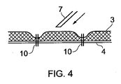
本発明による器具がどのように作製されるかを図4から見ることができる。希薄なおよび/または粘度の低い製品で器具を満たすことができるように、器具内に一時的な液体仕切りを形成する。この一時的な液体仕切りは底部層4と貯蔵層3を合わせて「溶接」することによって形成され、この場合「溶接」シームまたはバンド10によって閉回路が形成される。一時的な液体仕切りは、貯蔵小室8が形成されるとこの貯蔵小室8の中に配置される。
It can be seen from FIG. 4 how the device according to the invention is made. A temporary liquid divider is formed in the device so that the device can be filled with a lean and / or low viscosity product. This temporary liquid partition is formed by “welding” the
一時的な液体仕切りの目的は製品が一時的な仕切りを越えて流れるのを遅らせることであり、この遅れは器具内に貯蔵小室8を形成するには十分である。
The purpose of the temporary liquid partition is to delay the product from flowing past the temporary partition, and this delay is sufficient to form the
一時的な液体仕切りの中に液体を充填する目的でノズルまたは針7が使用される。針またはニードル7は次いで、それらを貯蔵層3の中に入れて貯蔵層3内に流体を直接注入する、あるいはそれらを貯蔵層3の表面に接触させて、または貯蔵層3より上の一定の距離のところに配置してこの面に流体を放出することができる。
A nozzle or
一時的な液体仕切りの溶接シーム10の幅は、溶接シームが流量調節装置として作用するため貯蔵層3内に貯蔵される液体および/またはコロイド状の物質に左右される。典型的には溶接シームの幅は0.5から2mmの範囲内である。
The width of the temporary liquid
一時的な液体仕切りの形態は円形から複雑な曲線まであらゆるものに変化し得るが、液体仕切りは常に閉回路である。 The form of the temporary liquid partition can vary from circular to complex curves, but the liquid partition is always a closed circuit.
さらに一時的な液体仕切りが貯蔵層3内に複数の閉鎖された区画を形成する場合もあり、これは器具が2つ以上の液体および/またはコロイド状の物質を含む際に有益である。
In addition, temporary liquid partitions may form a plurality of closed compartments in the
液体および/またはコロイド状の物質の特性(例えば重量および毛管現象力)により、液体および/またはコロイド状の物質は一時的な液体仕切りの中に分散し、液体および/またはコロイド状の物質はまた一時的な液体仕切りを越えて貯蔵層3の中に分散する。しかしながら液体のさらなる分散は、貯蔵小室8の液密の溶接部6によって制限される。
Depending on the properties of the liquid and / or colloidal material (eg weight and capillarity), the liquid and / or colloidal material is dispersed in the temporary liquid partition, and the liquid and / or colloidal material is also Disperses in the
液体および/またはコロイド状の物質が貯蔵小室3内の区画に充填された後、接触層2と貯蔵層1が貯蔵層3とポケット層4の上に置かれ、その後種々の層1−4が合わせて溶接されて貯蔵小室8を形成する。その後層の外側周辺部の内側および周囲に溶接部6が配置される。
After the liquid and / or colloidal substance has been filled into the compartments in the
1 頂部層
2 接触層
3 貯蔵層
4 底部層
5 ポケット層
6 溶接部
7 針またはノズル
8 貯蔵小室
9 溶接部
10 溶接シーム
DESCRIPTION OF SYMBOLS 1 Top layer 2
Claims (12)
Applications Claiming Priority (3)
| Application Number | Priority Date | Filing Date | Title |
|---|---|---|---|
| NO20090965A NO330398B1 (en) | 2009-03-03 | 2009-03-03 | Fluid barrier pad |
| NO20090965 | 2009-03-03 | ||
| PCT/NO2010/000080 WO2010101472A1 (en) | 2009-03-03 | 2010-03-01 | Pad with fluid barrier |
Publications (2)
| Publication Number | Publication Date |
|---|---|
| JP2012519531A JP2012519531A (en) | 2012-08-30 |
| JP5656089B2 true JP5656089B2 (en) | 2015-01-21 |
Family
ID=42111380
Family Applications (1)
| Application Number | Title | Priority Date | Filing Date |
|---|---|---|---|
| JP2011552900A Expired - Fee Related JP5656089B2 (en) | 2009-03-03 | 2010-03-01 | Pad with fluid divider |
Country Status (7)
| Country | Link |
|---|---|
| US (1) | US9161603B2 (en) |
| EP (1) | EP2403446B1 (en) |
| JP (1) | JP5656089B2 (en) |
| KR (1) | KR101775499B1 (en) |
| CN (1) | CN102421399B (en) |
| NO (1) | NO330398B1 (en) |
| WO (1) | WO2010101472A1 (en) |
Families Citing this family (20)
| Publication number | Priority date | Publication date | Assignee | Title |
|---|---|---|---|---|
| KR101615395B1 (en) | 2008-03-05 | 2016-04-25 | 케이씨아이 라이센싱 인코포레이티드 | Dressing and method for applying reduced pressure to and collecting and storing fluid from a tissue site |
| NO330404B1 (en) * | 2009-03-03 | 2011-04-04 | Padtech As | Pad with soft edges |
| US8814842B2 (en) | 2010-03-16 | 2014-08-26 | Kci Licensing, Inc. | Delivery-and-fluid-storage bridges for use with reduced-pressure systems |
| NO333266B1 (en) * | 2011-08-25 | 2013-04-29 | Padtech As | Pad with internal chamber and opening mechanism |
| AU2012352000B2 (en) | 2011-12-16 | 2017-06-29 | Solventum Intellectual Properties Company | Releasable medical drapes |
| US10940047B2 (en) | 2011-12-16 | 2021-03-09 | Kci Licensing, Inc. | Sealing systems and methods employing a hybrid switchable drape |
| SG11201503860RA (en) | 2012-11-16 | 2015-06-29 | Kci Licensing Inc | Medical drape with pattern adhesive layers and method of manufacturing same |
| JP6356022B2 (en) * | 2013-09-27 | 2018-07-11 | 株式会社イノアックコーポレーション | Gel covering and method for producing the same |
| EP3470030A1 (en) | 2013-10-28 | 2019-04-17 | KCI Licensing, Inc. | Hybrid sealing tape |
| WO2015065616A1 (en) | 2013-10-30 | 2015-05-07 | Kci Licensing, Inc. | Dressing with sealing and retention intereface |
| US9925092B2 (en) | 2013-10-30 | 2018-03-27 | Kci Licensing, Inc. | Absorbent conduit and system |
| CN110652396B (en) | 2013-10-30 | 2021-11-23 | 3M创新知识产权公司 | Dressing with perforations of different sizes |
| US10398814B2 (en) | 2013-10-30 | 2019-09-03 | Kci Licensing, Inc. | Condensate absorbing and dissipating system |
| KR101490682B1 (en) | 2013-12-09 | 2015-02-06 | 주식회사 코스메카코리아 | A method for charging liquid cosmetics having multi-colors |
| US10632020B2 (en) | 2014-02-28 | 2020-04-28 | Kci Licensing, Inc. | Hybrid drape having a gel-coated perforated mesh |
| US11026844B2 (en) | 2014-03-03 | 2021-06-08 | Kci Licensing, Inc. | Low profile flexible pressure transmission conduit |
| EP3281616B1 (en) | 2014-06-05 | 2020-01-01 | KCI Licensing, Inc. | Dressing with fluid acquisition and distribution characteristics |
| US11246975B2 (en) | 2015-05-08 | 2022-02-15 | Kci Licensing, Inc. | Low acuity dressing with integral pump |
| WO2017040045A1 (en) | 2015-09-01 | 2017-03-09 | Kci Licensing, Inc. | Dressing with increased apposition force |
| WO2017048866A1 (en) | 2015-09-17 | 2017-03-23 | Kci Licensing, Inc. | Hybrid silicone and acrylic adhesive cover for use with wound treatment |
Family Cites Families (23)
| Publication number | Priority date | Publication date | Assignee | Title |
|---|---|---|---|---|
| US3124825A (en) | 1964-03-17 | Iovenko | ||
| US3580254A (en) * | 1967-07-13 | 1971-05-25 | Henry P Stuart | Bandage containing a medicinal material and method of using |
| US4896768A (en) * | 1986-10-06 | 1990-01-30 | Lab Products, Inc. | Anti-bacterial and anti-viral presaturated wipe product |
| DE3725180A1 (en) * | 1987-07-29 | 1989-02-09 | Hecht Michael | Pack |
| US5254109A (en) * | 1992-12-07 | 1993-10-19 | Creative Products Resource Associates, Ltd. | Separately packaged applicator pads for topical delivery of incompatable drugs |
| IL113034A (en) * | 1994-04-05 | 2000-02-17 | Astra Ab | Topical dressing |
| US5480646A (en) * | 1994-10-12 | 1996-01-02 | Vu; Van N. | Pad for applying medicaments |
| GB9515807D0 (en) * | 1995-08-02 | 1995-10-04 | Cantwell Evelyna D | Topical hyperbaric bandage |
| US5961500A (en) | 1997-01-27 | 1999-10-05 | Weinstein; Robert E. | Prewetted medical wipe with impermeable barrier |
| US6169223B1 (en) * | 1999-02-08 | 2001-01-02 | Internationale Verbandstoff Fabrik Schaffhausen | Compress for medical treatment |
| AU2998900A (en) | 1999-02-19 | 2000-09-04 | Leslee S. Brooks | Zinc chloride in treating skin diseases |
| US7179007B2 (en) | 1999-10-08 | 2007-02-20 | The Procter & Gamble Company | Semi-enclosed applicators for distributing a substance onto a target surface |
| FR2811302B1 (en) * | 2000-07-06 | 2002-10-31 | Serge Wendel | PACKAGING FOR IMPREGNATED SUPPORT OF A SKIN APPLICATION PRODUCT |
| US20030106812A1 (en) * | 2001-09-19 | 2003-06-12 | Wilkman Michael A. | Impregnated wipe package with features improving handling and reducing transdermal migration |
| FR2846635B1 (en) * | 2002-10-30 | 2005-07-01 | D Lab | SINGLE USE PACKAGING FOR A DOSE OF PRODUCT |
| GB2414397B (en) * | 2004-05-26 | 2009-03-11 | Johnson And Johnson Medical Ltd | Self-irrigating wound dressing |
| US20050284777A1 (en) | 2004-06-23 | 2005-12-29 | Wilkman Michael A | Reservoir barrier wipes, pads and applicators |
| JP2006044793A (en) * | 2004-07-01 | 2006-02-16 | Nitto Denko Corp | Package for plaster patch |
| EP1965776A1 (en) | 2005-12-08 | 2008-09-10 | Fertin Pharma | Low flexural strength transdermal tobacco alkaloid patch |
| JP5224373B2 (en) * | 2006-06-06 | 2013-07-03 | 株式会社タイキ | Sheath-shaped applicator and method for manufacturing the same |
| DE102006047041A1 (en) * | 2006-10-02 | 2008-04-10 | Birgit Riesinger | Areal absorbent body |
| US20100292660A1 (en) * | 2007-07-10 | 2010-11-18 | Agis Kydonieus | Dermal delivery device with ultrasonic weld |
| NO330713B1 (en) * | 2008-08-13 | 2011-06-20 | Padtech As | Pad with scrub and brush function |
-
2009
- 2009-03-03 NO NO20090965A patent/NO330398B1/en not_active IP Right Cessation
-
2010
- 2010-03-01 US US13/254,459 patent/US9161603B2/en not_active Expired - Fee Related
- 2010-03-01 WO PCT/NO2010/000080 patent/WO2010101472A1/en active Application Filing
- 2010-03-01 CN CN201080019584.7A patent/CN102421399B/en not_active Expired - Fee Related
- 2010-03-01 KR KR1020117023155A patent/KR101775499B1/en active IP Right Grant
- 2010-03-01 JP JP2011552900A patent/JP5656089B2/en not_active Expired - Fee Related
- 2010-03-01 EP EP10710688.2A patent/EP2403446B1/en not_active Not-in-force
Also Published As
| Publication number | Publication date |
|---|---|
| US9161603B2 (en) | 2015-10-20 |
| WO2010101472A1 (en) | 2010-09-10 |
| NO330398B1 (en) | 2011-04-04 |
| CN102421399A (en) | 2012-04-18 |
| KR101775499B1 (en) | 2017-09-19 |
| KR20120002986A (en) | 2012-01-09 |
| EP2403446A1 (en) | 2012-01-11 |
| NO20090965L (en) | 2010-09-06 |
| EP2403446B1 (en) | 2014-12-31 |
| JP2012519531A (en) | 2012-08-30 |
| US20120059339A1 (en) | 2012-03-08 |
| CN102421399B (en) | 2015-04-29 |
Similar Documents
| Publication | Publication Date | Title |
|---|---|---|
| JP5656089B2 (en) | Pad with fluid divider | |
| JP5660398B2 (en) | Pad with soft edges | |
| KR101756784B1 (en) | Pad with brush/scrub function | |
| US9079208B2 (en) | Hinged pad with soft edge | |
| WO2009028952A1 (en) | Creampad | |
| US8926212B2 (en) | Pad with internal chamber and opening mechanism | |
| WO2009028951A1 (en) | Valve layer for pad | |
| WO2008060162A1 (en) | Pad with tearable sealing and a method of using the pad. |
Legal Events
| Date | Code | Title | Description |
|---|---|---|---|
| A621 | Written request for application examination |
Free format text: JAPANESE INTERMEDIATE CODE: A621 Effective date: 20130301 |
|
| A521 | Request for written amendment filed |
Free format text: JAPANESE INTERMEDIATE CODE: A523 Effective date: 20130416 |
|
| A521 | Request for written amendment filed |
Free format text: JAPANESE INTERMEDIATE CODE: A523 Effective date: 20130508 |
|
| A977 | Report on retrieval |
Free format text: JAPANESE INTERMEDIATE CODE: A971007 Effective date: 20140325 |
|
| A131 | Notification of reasons for refusal |
Free format text: JAPANESE INTERMEDIATE CODE: A131 Effective date: 20140415 |
|
| A521 | Request for written amendment filed |
Free format text: JAPANESE INTERMEDIATE CODE: A523 Effective date: 20140522 |
|
| TRDD | Decision of grant or rejection written | ||
| A01 | Written decision to grant a patent or to grant a registration (utility model) |
Free format text: JAPANESE INTERMEDIATE CODE: A01 Effective date: 20141014 |
|
| A61 | First payment of annual fees (during grant procedure) |
Free format text: JAPANESE INTERMEDIATE CODE: A61 Effective date: 20141112 |
|
| R150 | Certificate of patent or registration of utility model |
Ref document number: 5656089 Country of ref document: JP Free format text: JAPANESE INTERMEDIATE CODE: R150 |
|
| LAPS | Cancellation because of no payment of annual fees |