JP5656013B2 - Engine automatic stop / start control device - Google Patents
Engine automatic stop / start control device Download PDFInfo
- Publication number
- JP5656013B2 JP5656013B2 JP2010265000A JP2010265000A JP5656013B2 JP 5656013 B2 JP5656013 B2 JP 5656013B2 JP 2010265000 A JP2010265000 A JP 2010265000A JP 2010265000 A JP2010265000 A JP 2010265000A JP 5656013 B2 JP5656013 B2 JP 5656013B2
- Authority
- JP
- Japan
- Prior art keywords
- engine
- rotational speed
- pinion
- rotation speed
- ring gear
- Prior art date
- Legal status (The legal status is an assumption and is not a legal conclusion. Google has not performed a legal analysis and makes no representation as to the accuracy of the status listed.)
- Active
Links
Images


Classifications
-
- F—MECHANICAL ENGINEERING; LIGHTING; HEATING; WEAPONS; BLASTING
- F02—COMBUSTION ENGINES; HOT-GAS OR COMBUSTION-PRODUCT ENGINE PLANTS
- F02N—STARTING OF COMBUSTION ENGINES; STARTING AIDS FOR SUCH ENGINES, NOT OTHERWISE PROVIDED FOR
- F02N11/00—Starting of engines by means of electric motors
- F02N11/08—Circuits specially adapted for starting of engines
- F02N11/0851—Circuits specially adapted for starting of engines characterised by means for controlling the engagement or disengagement between engine and starter, e.g. meshing of pinion and engine gear
- F02N11/0855—Circuits specially adapted for starting of engines characterised by means for controlling the engagement or disengagement between engine and starter, e.g. meshing of pinion and engine gear during engine shutdown or after engine stop before start command, e.g. pre-engagement of pinion
-
- F—MECHANICAL ENGINEERING; LIGHTING; HEATING; WEAPONS; BLASTING
- F02—COMBUSTION ENGINES; HOT-GAS OR COMBUSTION-PRODUCT ENGINE PLANTS
- F02N—STARTING OF COMBUSTION ENGINES; STARTING AIDS FOR SUCH ENGINES, NOT OTHERWISE PROVIDED FOR
- F02N11/00—Starting of engines by means of electric motors
- F02N11/08—Circuits specially adapted for starting of engines
- F02N11/0814—Circuits specially adapted for starting of engines comprising means for controlling automatic idle-start-stop
- F02N11/0818—Conditions for starting or stopping the engine or for deactivating the idle-start-stop mode
-
- F—MECHANICAL ENGINEERING; LIGHTING; HEATING; WEAPONS; BLASTING
- F02—COMBUSTION ENGINES; HOT-GAS OR COMBUSTION-PRODUCT ENGINE PLANTS
- F02N—STARTING OF COMBUSTION ENGINES; STARTING AIDS FOR SUCH ENGINES, NOT OTHERWISE PROVIDED FOR
- F02N11/00—Starting of engines by means of electric motors
- F02N11/08—Circuits specially adapted for starting of engines
- F02N11/0814—Circuits specially adapted for starting of engines comprising means for controlling automatic idle-start-stop
- F02N11/0844—Circuits specially adapted for starting of engines comprising means for controlling automatic idle-start-stop with means for restarting the engine directly after an engine stop request, e.g. caused by change of driver mind
-
- F—MECHANICAL ENGINEERING; LIGHTING; HEATING; WEAPONS; BLASTING
- F02—COMBUSTION ENGINES; HOT-GAS OR COMBUSTION-PRODUCT ENGINE PLANTS
- F02N—STARTING OF COMBUSTION ENGINES; STARTING AIDS FOR SUCH ENGINES, NOT OTHERWISE PROVIDED FOR
- F02N11/00—Starting of engines by means of electric motors
- F02N11/08—Circuits specially adapted for starting of engines
- F02N11/0859—Circuits specially adapted for starting of engines specially adapted to the type of the starter motor or integrated into it
-
- F—MECHANICAL ENGINEERING; LIGHTING; HEATING; WEAPONS; BLASTING
- F02—COMBUSTION ENGINES; HOT-GAS OR COMBUSTION-PRODUCT ENGINE PLANTS
- F02N—STARTING OF COMBUSTION ENGINES; STARTING AIDS FOR SUCH ENGINES, NOT OTHERWISE PROVIDED FOR
- F02N2200/00—Parameters used for control of starting apparatus
- F02N2200/02—Parameters used for control of starting apparatus said parameters being related to the engine
- F02N2200/022—Engine speed
-
- F—MECHANICAL ENGINEERING; LIGHTING; HEATING; WEAPONS; BLASTING
- F02—COMBUSTION ENGINES; HOT-GAS OR COMBUSTION-PRODUCT ENGINE PLANTS
- F02N—STARTING OF COMBUSTION ENGINES; STARTING AIDS FOR SUCH ENGINES, NOT OTHERWISE PROVIDED FOR
- F02N2300/00—Control related aspects of engine starting
- F02N2300/20—Control related aspects of engine starting characterised by the control method
- F02N2300/2006—Control related aspects of engine starting characterised by the control method using prediction of future conditions
-
- F—MECHANICAL ENGINEERING; LIGHTING; HEATING; WEAPONS; BLASTING
- F02—COMBUSTION ENGINES; HOT-GAS OR COMBUSTION-PRODUCT ENGINE PLANTS
- F02N—STARTING OF COMBUSTION ENGINES; STARTING AIDS FOR SUCH ENGINES, NOT OTHERWISE PROVIDED FOR
- F02N99/00—Subject matter not provided for in the other groups of this subclass
- F02N99/002—Starting combustion engines by ignition means
- F02N99/006—Providing a combustible mixture inside the cylinder
-
- Y—GENERAL TAGGING OF NEW TECHNOLOGICAL DEVELOPMENTS; GENERAL TAGGING OF CROSS-SECTIONAL TECHNOLOGIES SPANNING OVER SEVERAL SECTIONS OF THE IPC; TECHNICAL SUBJECTS COVERED BY FORMER USPC CROSS-REFERENCE ART COLLECTIONS [XRACs] AND DIGESTS
- Y02—TECHNOLOGIES OR APPLICATIONS FOR MITIGATION OR ADAPTATION AGAINST CLIMATE CHANGE
- Y02T—CLIMATE CHANGE MITIGATION TECHNOLOGIES RELATED TO TRANSPORTATION
- Y02T10/00—Road transport of goods or passengers
- Y02T10/10—Internal combustion engine [ICE] based vehicles
- Y02T10/40—Engine management systems
Landscapes
- Engineering & Computer Science (AREA)
- Chemical & Material Sciences (AREA)
- Combustion & Propulsion (AREA)
- Mechanical Engineering (AREA)
- General Engineering & Computer Science (AREA)
- Control Of Vehicle Engines Or Engines For Specific Uses (AREA)
- Output Control And Ontrol Of Special Type Engine (AREA)
- Electrical Control Of Air Or Fuel Supplied To Internal-Combustion Engine (AREA)
Description
本発明は、エンジン自動停止要求が発生したときにエンジンを自動停止させ、エンジン再始動要求が発生したときにエンジンを再始動させるエンジン自動停止始動制御装置に関する発明である。 The present invention relates to an engine automatic stop start control device that automatically stops an engine when an engine automatic stop request is generated and restarts the engine when an engine restart request is generated.
近年、エンジン(内燃機関)を搭載した車両においては、燃費節減、排気エミッション低減等を目的として、エンジン自動停止始動制御システム(いわゆるアイドルストップ制御システム)を採用したものがある。このエンジン自動停止始動制御システムは、例えば、運転者が車両を停車させたときにエンジンを自動的に停止させ、その後、運転者が車両を発進させようとする操作を行ったときに自動的にスタータでエンジンをクランキングして再始動させるようにしている。 In recent years, some vehicles equipped with an engine (internal combustion engine) employ an engine automatic stop / start control system (so-called idle stop control system) for the purpose of reducing fuel consumption and exhaust emission. This engine automatic stop / start control system automatically stops the engine when the driver stops the vehicle, for example, and then automatically when the driver performs an operation to start the vehicle. The engine is cranked with a starter and restarted.
一般に、スタータは、モータでピニオンを回転させると共に、アクチュエータでピニオンを押し出して該ピニオンをエンジンのクランク軸に連結されたリングギヤに噛み合わせてリングギヤを回転駆動することで、エンジンをクランキングするようになっているが、ピニオンとリングギヤの回転速度の差が大きい状態でピニオンをリングギヤに噛み合わせようとすると、ピニオンがリングギヤにスムーズに噛み合わずに騒音が発生する可能性がある。 Generally, a starter rotates a pinion with a motor, pushes out the pinion with an actuator, meshes the pinion with a ring gear connected to the crankshaft of the engine, and drives the ring gear to rotate so that the engine is cranked. However, if the pinion tries to mesh with the ring gear while the difference in rotational speed between the pinion and the ring gear is large, the pinion may not mesh smoothly with the ring gear and noise may be generated.
そこで、特許文献1(特開2002−122059号公報)に記載されているように、エンジン自動停止要求が発生した直後でエンジンの自動停止によりエンジン回転速度が降下するエンジン回転降下期間中にエンジン再始動要求が発生した場合には、その後、エンジン回転(リングギヤの回転)がほぼ停止してから、スタータのピニオンをリングギヤに噛み合わせた後にピニオンを回転させて、スタータによるクランキングを開始してエンジンを再始動させるようにしたものがある。 Therefore, as described in Patent Document 1 (Japanese Patent Laid-Open No. 2002-122059), immediately after the engine automatic stop request is generated, the engine restart is performed during the engine rotation drop period in which the engine rotation speed decreases due to the automatic engine stop. When a start request is generated, after the engine rotation (rotation of the ring gear) has almost stopped, the pinion of the starter is engaged with the ring gear and then the pinion is rotated to start cranking by the starter. There is something that restarts.
しかし、上記特許文献1の技術では、エンジンの自動停止によるエンジン回転降下期間中にエンジン再始動要求が発生した場合に、その後、エンジン回転がほぼ停止するまで待ってから、スタータによるクランキングを開始してエンジンを再始動させるため、エンジン再始動要求からエンジンを再始動させるまでの遅れが大きくなってしまい、運転者にエンジンの再始動が遅いと感じさせてしまう可能性がある。
However, in the technique of the above-mentioned
この対策として、特許文献2(特開2005−330813号公報)や特許文献3(特開2002−70699号公報)に記載されているように、エンジンの自動停止によるエンジン回転降下期間中にエンジン再始動要求が発生したときに、ピニオンの回転速度をリングギヤの回転速度に同期させて両者の回転速度の差を小さくした後にピニオンをリングギヤに噛み合わせて、スタータによるクランキングを開始してエンジンを再始動させるようにしたものがある。 As a countermeasure against this, as described in Patent Document 2 (Japanese Patent Laid-Open No. 2005-330813) and Patent Document 3 (Japanese Patent Laid-Open No. 2002-70699), the engine is restarted during the engine rotation descent period due to the automatic stop of the engine. When a start-up request is generated, the pinion rotation speed is synchronized with the ring gear rotation speed to reduce the difference between the two rotation speeds, the pinion is engaged with the ring gear, cranking by the starter is started, and the engine is restarted. There is something to be started.
しかしながら、上記特許文献2や上記特許文献3の技術では、単に、ピニオンとリングギヤの回転速度を同期した時点でピニオンとリングギヤを噛み合わせるとの記載のみであり、この噛み合せタイミングに関する記載が非常に少なく、良好な噛み合せの実現には、いまだ実用化に達していないといわざるをえない状況である。
However, the techniques of
そこで、本発明が解決しようとする課題は、エンジンの自動停止によるエンジン回転降下期間中にエンジン再始動要求が発生したとしても、スムーズにエンジンの再始動を行うことができるエンジン自動停止始動制御装置を提供することにある。 Therefore, the problem to be solved by the present invention is to provide an engine automatic stop / start control device capable of smoothly restarting an engine even when an engine restart request is generated during an engine rotation descent period due to the automatic engine stop. Is to provide.
上記目的を達成するために、請求項1に係る発明は、ピニオンを回転駆動するモータと、このピニオンをエンジンのクランク軸に連結されたリングギヤに噛み合わせるアクチュエータとを個別に作動可能なスタータを備え、エンジン自動停止要求が発生したときにエンジンを自動停止させ、エンジン再始動要求が発生したときにエンジンを再始動させるエンジン自動停止始動制御装置において、エンジンの自動停止によりエンジン回転速度が降下するエンジン回転降下期間中にエンジン回転速度が第1の回転速度よりも高い第1の回転速度領域でエンジン再始動要求が発生したときに、スタータによるクランキングを行わずに燃料噴射を再開してエンジンを再始動させる第1の再始動制御手段と、エンジン回転降下期間中にエンジン回転速度が第1の回転速度以下で第2の回転速度よりも高い第2の回転速度領域でエンジン再始動要求が発生したときに、モータによりピニオンの回転速度をリングギヤの回転速度に同期させた後にアクチュエータによりピニオンをリングギヤに噛み合わせてスタータによるクランキングを開始してエンジンを再始動させる第2の再始動制御手段と、エンジン回転降下期間中にエンジン回転速度が第2の回転速度以下で且つ50〜450rpmの範囲内に設定された第3の回転速度よりも高い待機回転速度領域でエンジン再始動要求が発生したときに、スタータによるクランキングを行わずに、その後、エンジン回転速度が第3の回転速度以下の第3の回転速度領域になったときに、アクチュエータによりピニオンをリングギヤに噛み合わせた後又はその噛み合わせの途中にモータによりピニオンを回転させてスタータによるクランキングを開始してエンジンを再始動させる待機再始動制御手段と、エンジン回転降下期間中にエンジン回転速度が第3の回転速度以下の第3の回転速度領域でエンジン再始動要求が発生したときに、アクチュエータによりピニオンをリングギヤに噛み合わせた後又はその噛み合わせの途中にモータによりピニオンを回転させてスタータによるクランキングを開始してエンジンを再始動させる第3の再始動制御手段とを備えた構成としたものである。
To achieve the above object, the invention according to
この構成では、エンジンの自動停止によるエンジン回転降下期間中にエンジン回転速度が比較的高い第1の回転速度領域でエンジン再始動要求が発生したときには、スタータによるクランキングを行わなくてもエンジンを再始動できると判断して、スタータによるクランキングを行わずに燃料噴射を再開してエンジンを再始動させることができる。これにより、エンジン再始動要求が発生したときに、直ちにエンジンの燃焼を再開してエンジンを速やかに再始動させることができる。しかも、スタータによるクランキングを行わないため、スタータの電力消費量を0にすることができると共に、ピニオンとリングギヤの回転速度の差が大きい状態でピニオンをリングギヤに噛み合わせることを回避して、騒音の発生を防止することができる。 In this configuration, when an engine restart request is generated in the first rotation speed region where the engine rotation speed is relatively high during the engine rotation drop period due to the automatic engine stop, the engine is restarted without performing cranking by the starter. It can be determined that the engine can be started, and the engine can be restarted by restarting fuel injection without performing cranking by the starter. Thereby, when the engine restart request | requirement generate | occur | produces, combustion of an engine can be restarted immediately and an engine can be restarted rapidly. In addition, since starter cranking is not performed, the power consumption of the starter can be reduced to zero, and it is possible to avoid the meshing of the pinion with the ring gear when there is a large difference in rotational speed between the pinion and the ring gear. Can be prevented.
また、エンジンの自動停止によるエンジン回転降下期間中にエンジン回転速度が第2の回転速度領域でエンジン再始動要求が発生したときには、リングギヤの回転速度が比較的高いため、ピニオンの回転速度をリングギヤの回転速度に同期させないと、ピニオンをリングギヤにスムーズに噛み合わせることができないと判断して、モータによりピニオンの回転速度をリングギヤの回転速度に同期させて両者の回転速度の差を小さくした後にアクチュエータによりピニオンをリングギヤに噛み合わせてスタータによるクランキングを開始してエンジンを再始動させることができる。これにより、ピニオンをリングギヤにスムーズに噛み合わせて騒音の発生を防止しながら、エンジン再始動要求からエンジンを再始動させるまでの遅れを小さくすることができる。 Further, when the engine restart request is generated in the second rotational speed region during the engine rotational speed drop period due to the automatic engine stop, the rotational speed of the ring gear is relatively high. If it is determined that the pinion cannot be smoothly meshed with the ring gear unless it is synchronized with the rotational speed, the actuator synchronizes the rotational speed of the pinion with the rotational speed of the ring gear to reduce the difference between the rotational speeds of the two. The pinion is engaged with the ring gear, cranking by the starter is started, and the engine can be restarted. Thus, the delay from the engine restart request to the engine restart can be reduced while the pinion is smoothly meshed with the ring gear to prevent the generation of noise.
更に、エンジンの自動停止によるエンジン回転降下期間中にエンジン回転速度が比較的低い第3の回転速度領域でエンジン再始動要求が発生したときには、リングギヤの回転速度が比較的低いため、ピニオンの回転速度をリングギヤの回転速度に同期させなくても、ピニオンをリングギヤにスムーズに噛み合わせることができると判断して、アクチュエータによりピニオンをリングギヤに噛み合わせた後又はその噛み合わせの途中にモータによりピニオンを回転させてスタータによるクランキングを開始してエンジンを再始動させることができる。これにより、ピニオンをリングギヤにスムーズに噛み合わせて騒音の発生を防止しながら、ピニオンの回転速度をリングギヤの回転速度に同期させる処理を省略することができるため、その分、スタータによるクランキングの開始を早くしてエンジンを速やかに再始動させることができると共に、スタータの電力消費量を低減することができる。 Further, when the engine restart request is generated in the third rotational speed region where the engine rotational speed is relatively low during the engine rotational speed drop period due to the automatic engine stop, the rotational speed of the pinion is relatively low because the rotational speed of the ring gear is relatively low. Even if the pinion can be smoothly meshed with the ring gear without synchronizing with the rotation speed of the ring gear, the pinion is rotated by the motor after the pinion is meshed with the ring gear by the actuator or during the meshing. The cranking by the starter can be started and the engine can be restarted. As a result, the process of synchronizing the rotation speed of the pinion with the rotation speed of the ring gear can be omitted while smoothly engaging the pinion with the ring gear to prevent the generation of noise. The engine can be restarted quickly and the power consumption of the starter can be reduced.
また、本発明者らの研究によると、第2の回転速度領域と第3の回転速度領域との間に待機回転速度領域を設けずに、第2の回転速度領域と第3の回転速度領域とを隣接させるように設定した場合には、次のような問題が発生することが判明した。図9に示すように、一般にエンジンの自動停止によるエンジン回転降下期間中にエンジン回転速度は脈動しながら降下するため、第2の回転速度領域と第3の回転速度領域とを隣接させた場合には、エンジン回転速度が第2の回転速度領域と第3の回転速度領域とを行き来しながら低下する。このため、第2の回転速度領域と第3の回転速度領域との境界付近では、エンジン回転速度が第2の回転速度領域でエンジン再始動要求が発生しても、その後すぐにエンジン回転速度が第3の回転速度領域に入ったり、或は、エンジン回転速度が第3の回転速度領域でエンジン再始動要求が発生しても、その後すぐにエンジン回転速度が第2の回転速度領域に戻ったりする可能性がある。これにより、エンジン回転速度の予測を必要とする複雑な再始動制御を行わなければ、適正な再始動制御を行うことが困難となり、スムーズにエンジンの再始動を行うことができない。 Further, according to the study by the present inventors, the second rotational speed region and the third rotational speed region are provided without providing the standby rotational speed region between the second rotational speed region and the third rotational speed region. It has been found that the following problems occur when they are set to be adjacent to each other. As shown in FIG. 9, the engine rotation speed generally decreases while pulsating during the engine rotation drop period due to the automatic stop of the engine. Therefore, when the second rotation speed area and the third rotation speed area are adjacent to each other. The engine rotational speed decreases while going back and forth between the second rotational speed region and the third rotational speed region. Therefore, in the vicinity of the boundary between the second rotation speed region and the third rotation speed region, even if an engine restart request is generated in the second rotation speed region, the engine rotation speed immediately follows. Entering the third rotation speed region, or even if an engine restart request is generated when the engine rotation speed is in the third rotation speed region, the engine rotation speed immediately returns to the second rotation speed region. there's a possibility that. As a result, unless complicated restart control that requires prediction of the engine rotation speed is performed, it is difficult to perform proper restart control, and the engine cannot be restarted smoothly.
そこで、本発明は、第2の回転速度領域と第3の回転速度領域との間に待機回転速度領域を設定し、この待機回転速度領域でエンジン再始動要求が発生したときには、スタータによるクランキングを行わずに、その後、エンジン回転速度が第3の回転速度領域になったときに、アクチュエータによりピニオンをリングギヤに噛み合わせた後又はその噛み合わせの途中にモータによりピニオンを回転させてスタータによるクランキングを開始してエンジンを再始動させる。これにより、第2の回転速度領域と第3の回転速度領域との間の領域(待機回転速度領域)でエンジン再始動要求が発生した場合でも、エンジン回転速度の予測を必要とする複雑な再始動制御を行うことなく、スムーズにエンジンの再始動を行うことができる。この場合、エンジン回転速度が待機回転速度領域でエンジン再始動要求が発生しても、その後、エンジン回転速度が第3の回転速度領域になってから、スタータによるクランキングを開始してエンジンを再始動させることになるが、エンジン回転速度が待機回転速度領域を通過する時間は比較的短いため、エンジン再始動要求からエンジンを再始動させるまでの遅れを許容範囲内に抑えることができる。 Therefore, according to the present invention, a standby rotational speed region is set between the second rotational speed region and the third rotational speed region, and when an engine restart request is generated in this standby rotational speed region, cranking by a starter is performed. After that, when the engine rotation speed becomes the third rotation speed region, after the pinion is engaged with the ring gear by the actuator or during the engagement, the pinion is rotated by the motor and the starter is Start ranking and restart the engine. As a result, even when an engine restart request is generated in a region between the second rotational speed region and the third rotational speed region (standby rotational speed region), a complicated re-operation that requires prediction of the engine rotational speed is required. The engine can be restarted smoothly without starting control. In this case, even if an engine restart request occurs when the engine rotational speed is in the standby rotational speed region, cranking by the starter is started after the engine rotational speed has reached the third rotational speed region, and the engine is restarted. Although the engine is started, since the time during which the engine speed passes through the standby rotation speed region is relatively short, the delay from the engine restart request until the engine is restarted can be suppressed within an allowable range.
尚、本発明は、第1の再始動制御手段(スタータによるクランキングを行わずに燃料噴射を再開してエンジンを再始動させる手段)を備えた構成に限定されず、上記請求項1の構成から第1の再始動制御手段を省略した構成(請求項2の構成)としても良い。
The present invention is not limited to the configuration provided with the first restart control means (means for restarting the fuel injection without restarting the cranking by the starter), and the configuration according to
更に、請求項3のように、第2の再始動制御手段は、リングギヤの回転速度とピニオンの回転速度との回転速度差が±200rpmの範囲内になったときにピニオンの回転速度がリングギヤの回転速度に同期したと判断するようにすると良い。このようにすれば、ピニオンの回転速度がリングギヤの回転速度に同期したと判断してピニオンをリングギヤに噛み合わせる際の騒音の発生を防止することができる。ここで、リングギヤの回転速度とピニオンの回転速度との回転速度差における「回転速度差」とは、「クランク軸に換算した回転速度差」を意味する(以下、同様)。 Further, as in claim 3, the second restart control means is configured such that when the rotational speed difference between the rotational speed of the ring gear and the rotational speed of the pinion is within a range of ± 200 rpm, the rotational speed of the pinion is It is good to judge that it is synchronized with the rotation speed. In this way, it is possible to prevent the occurrence of noise when it is determined that the rotation speed of the pinion is synchronized with the rotation speed of the ring gear and the pinion is engaged with the ring gear. Here, the “rotational speed difference” in the rotational speed difference between the rotational speed of the ring gear and the rotational speed of the pinion means “the rotational speed difference converted into the crankshaft” (the same applies hereinafter).
或は、請求項4のように、第2の再始動制御手段は、リングギヤのピッチ円上の周速度とピニオンのピッチ円上の周速度との周速度差が±3.1m/秒の範囲内になったときにピニオンの回転速度がリングギヤの回転速度に同期したと判断するようにしても良い。このようにしても、前記請求項3とほぼ同じ効果を得ることができる。 Alternatively, according to a fourth aspect of the present invention, in the second restart control means, the peripheral speed difference between the peripheral speed on the pitch circle of the ring gear and the peripheral speed on the pitch circle of the pinion is within a range of ± 3.1 m / sec. It is also possible to determine that the rotational speed of the pinion is synchronized with the rotational speed of the ring gear when it is inside. Even if it does in this way, the substantially same effect as the said Claim 3 can be acquired.
また、請求項5のように、スタータに、エンジン回転方向においてピニオンからモータへ動力を伝達しないワンウエイクラッチが設けられたシステムの場合には、第2の再始動制御手段は、リングギヤの回転速度がピニオンの回転速度よりも高く且つリングギヤの回転速度とピニオンの回転速度との回転速度差が所定値以下になったときにピニオンの回転速度がリングギヤの回転速度に同期したと判断するようにしても良い。このようにすれば、ピニオンの回転速度がリングギヤの回転速度に同期したと判断してピニオンをリングギヤに噛み合わせる際に、リングギヤの回転速度がピニオンの回転速度よりも高いときにピニオンをリングギヤに噛み合わせるが、ワンウエイクラッチが空転してスタータに加わる衝撃を緩和することができ、その後、フリクションによるエンジン回転速度(リングギヤの回転速度)の低下とモータの回転速度(ピニオンの回転速度)の上昇に伴って、リングギヤの回転速度とピニオンの回転速度との回転速度差が0になったときに、ワンウエイクラッチがロックしてモータからピニオンへ動力が伝達され始める。このような挙動により、ピニオンをリングギヤに比較的スムーズに噛み合わせることができ、スタータの構成部品への衝撃も少なく、強度的に余裕を持たせることができる。 Further, as in claim 5, in the case of a system in which the starter is provided with a one-way clutch that does not transmit power from the pinion to the motor in the engine rotation direction, the second restart control means is configured such that the rotational speed of the ring gear is It may be determined that the rotation speed of the pinion is synchronized with the rotation speed of the ring gear when the rotation speed is higher than the rotation speed of the pinion and the rotation speed difference between the rotation speed of the ring gear and the rotation speed of the pinion becomes a predetermined value or less. good. In this way, when it is determined that the rotation speed of the pinion is synchronized with the rotation speed of the ring gear and the pinion is meshed with the ring gear, the pinion is meshed with the ring gear when the rotation speed of the ring gear is higher than the rotation speed of the pinion. In addition, the one-way clutch is idled and the impact applied to the starter can be mitigated. Then, as the engine speed (ring gear speed) decreases due to friction and the motor speed (pinion speed) increases Thus, when the rotational speed difference between the rotational speed of the ring gear and the rotational speed of the pinion becomes zero, the one-way clutch is locked and power is transmitted from the motor to the pinion. With such a behavior, the pinion can be meshed with the ring gear relatively smoothly, the impact on the components of the starter can be reduced, and a sufficient margin can be provided.
この場合、請求項6のように、所定値は、300rpm以下の値に設定すると良く、具体的には、請求項7のように、所定値は、200rpmに設定すると良い。このようにすれば、リングギヤの回転速度とピニオンの回転速度との同期を判断する際の回転速度の検出精度をあまり高くする必要がないため、リングギヤの回転速度を精度良く検出できる高価なクランク角センサやピニオンの回転速度を精度良く検出できる高価な回転速度センサを設ける必要がなく、近年の重要な技術的課題である低コスト化の要求を満たすことができる。 In this case, as in claim 6, the predetermined value may be set to a value of 300 rpm or less. Specifically, as in claim 7, the predetermined value may be set to 200 rpm. In this way, since it is not necessary to increase the detection accuracy of the rotation speed when determining the synchronization between the rotation speed of the ring gear and the rotation speed of the pinion, an expensive crank angle that can accurately detect the rotation speed of the ring gear. It is not necessary to provide an expensive rotation speed sensor that can accurately detect the rotation speed of the sensor and the pinion, and it is possible to meet the demand for cost reduction, which is an important technical problem in recent years.
或は、請求項8のように、スタータにワンウエイクラッチが設けられたシステムの場合に、第2の再始動制御手段は、リングギヤのピッチ円上の周速度がピニオンのピッチ円上の周速度よりも高く且つリングギヤのピッチ円上の周速度とピニオンのピッチ円上の周速度との周速度差が3.1m/秒の範囲内になったときにピニオンの回転速度がリングギヤの回転速度に同期したと判断するようにしても良い。このようにしても、前記請求項5とほぼ同じ効果を得ることができる。 Alternatively, in the case of a system in which the one-way clutch is provided in the starter as in claim 8, the second restart control means is configured such that the peripheral speed on the pitch circle of the ring gear is greater than the peripheral speed on the pitch circle of the pinion. The rotation speed of the pinion is synchronized with the rotation speed of the ring gear when the peripheral speed difference between the peripheral speed on the pitch circle of the ring gear and the peripheral speed on the pitch circle of the pinion is within the range of 3.1 m / sec. You may make it judge that it was. Even if it does in this way, the effect substantially the same as the said Claim 5 can be acquired.
また、請求項9のように、エンジンの自動停止によりエンジン回転速度が降下するエンジン回転降下期間中にエンジン回転速度が第1の回転速度よりも高い第1の回転速度領域でエンジン再始動要求が発生したときに、スタータによるクランキングを行わずに燃料噴射を再開してエンジンを再始動させる第1の再始動制御手段と、エンジン回転降下期間中にエンジン回転速度が第1の回転速度以下で第2の回転速度よりも高い待機回転速度領域でエンジン再始動要求が発生したときに、スタータによるクランキングを行わずに、その後、エンジン回転速度が第2の回転速度以下で且つ50〜450rpmの範囲内に設定された第3の回転速度よりも高い第2の回転速度領域になったときに、モータによりピニオンの回転速度をリングギヤの回転速度に同期させた後にアクチュエータによりピニオンをリングギヤに噛み合わせてスタータによるクランキングを開始してエンジンを再始動させる待機再始動制御手段とを備えた構成としても良い。 According to a ninth aspect of the present invention, an engine restart request is issued in a first rotational speed region in which the engine rotational speed is higher than the first rotational speed during an engine rotational speed decrease period in which the engine rotational speed decreases due to automatic engine stop. A first restart control means for restarting the engine by restarting fuel injection without performing cranking by a starter, and when the engine rotation speed is lower than the first rotation speed during the engine rotation drop period When an engine restart request is generated in a standby rotational speed range higher than the second rotational speed, cranking by the starter is not performed, and thereafter, the engine rotational speed is equal to or lower than the second rotational speed and 50 to 450 rpm. third when it is higher second rotational speed region than the rotational speed, the ring gear rotation speed of the pinion by the motor of times that is set in the range And a pinion engaged with the ring gear by the actuator to start the cranking by the starter may be configured to include a stand-restart control means for restarting the engine after synchronizing to the speed.
このようにすれば、第1の回転速度領域と第2の回転速度領域との間の領域(待機回転速度領域)でエンジン再始動要求が発生した場合でも、エンジン回転速度の予測を必要とする複雑な再始動制御を行うことなく、スムーズにエンジンの再始動を行うことができる。この場合、エンジン回転速度が待機回転速度領域でエンジン再始動要求が発生しても、その後、エンジン回転速度が第2の回転速度領域になってから、スタータによるクランキングを開始してエンジンを再始動させることになるが、エンジン回転速度が待機回転速度領域を通過する時間は比較的短いため、エンジン再始動要求からエンジンを再始動させるまでの遅れを許容範囲内に抑えることができる。 In this way, even when an engine restart request is generated in a region (standby rotational speed region) between the first rotational speed region and the second rotational speed region, it is necessary to predict the engine rotational speed. The engine can be restarted smoothly without complicated restart control. In this case, even if an engine restart request occurs when the engine rotational speed is in the standby rotational speed region, cranking by the starter is started after the engine rotational speed has entered the second rotational speed region, and the engine is restarted. Although the engine is started, since the time during which the engine speed passes through the standby rotation speed region is relatively short, the delay from the engine restart request until the engine is restarted can be suppressed within an allowable range.
また、請求項10のように、第1の回転速度は、300〜700rpmの範囲内に設定するようにすると良い。要するに、エンジン回転降下期間中にエンジン回転速度が第1の回転速度(300〜700rpm)よりも高いときには、スタータによるクランキングを行わなくてもエンジンを再始動できるため、第1の回転速度を300〜700rpmの範囲内に設定すれば、第1の回転速度(300〜700rpm)よりも高い第1の回転速度領域が、スタータによるクランキングを行わずに燃料噴射を再開してエンジンを再始動できる領域となる。 Further, as in claim 10, the first rotation speed is preferably set within a range of 300 to 700 rpm. In short, when the engine rotation speed is higher than the first rotation speed (300 to 700 rpm) during the engine rotation drop period, the engine can be restarted without cranking by the starter. If it is set within the range of ˜700 rpm, the first rotational speed region higher than the first rotational speed (300 to 700 rpm) can restart the fuel injection without restarting the cranking by the starter. It becomes an area.
更に、請求項1,2,9のように、第3の回転速度は、50〜450rpmの範囲内に設定するようにすると良い。要するに、エンジン回転降下期間中にエンジン回転速度が第3の回転速度(50〜450rpm)以下に低下すると、ピニオンの回転速度をリングギヤの回転速度に同期させなくても、ピニオンをリングギヤにスムーズに噛み合わせることができるため、第3の回転速度を50〜450rpmの範囲内に設定すれば、第3の回転速度(50〜450rpm)以下の第3の回転速度領域が、ピニオンの回転速度をリングギヤの回転速度に同期させなくても、ピニオンをリングギヤにスムーズに噛み合わせることができる領域となる。 Further, as in the first, second, and ninth aspects , the third rotational speed may be set within a range of 50 to 450 rpm. In short, if the engine speed drops below the third speed (50 to 450 rpm) during the engine speed drop period, the pinion smoothly meshes with the ring gear without synchronizing the pinion speed with the ring gear speed. Therefore, if the third rotation speed is set within the range of 50 to 450 rpm, the third rotation speed region below the third rotation speed (50 to 450 rpm) will cause the rotation speed of the pinion to This is a region where the pinion can be smoothly meshed with the ring gear without being synchronized with the rotation speed.
また、請求項11のように、第2の回転速度は、第3の回転速度よりも50〜150rpm高い回転速度に設定するようにすると良い。このようにすれば、第2の回転速度以下で第3の回転速度よりも高い待機回転速度領域(又は第1の回転速度以下で第2の回転速度よりも高い待機回転速度領域)を適正に設定することができる。 Further, as in the eleventh aspect , the second rotation speed may be set to a rotation speed higher by 50 to 150 rpm than the third rotation speed. In this way, a standby rotational speed region that is lower than the second rotational speed and higher than the third rotational speed (or a standby rotational speed region that is lower than the first rotational speed and higher than the second rotational speed) is appropriately set. Can be set.
また、請求項12のように、エンジンの自動停止によりエンジン回転速度が降下するエンジン回転降下期間中にエンジン回転速度が第1の回転速度よりも高い第1の回転速度領域でエンジン再始動要求が発生したときに、スタータによるクランキングを行わずに燃料噴射を再開してエンジンを再始動させる第1の再始動制御手段と、エンジン回転降下期間中にエンジン回転速度が第1の回転速度以下で且つ50〜450rpmの範囲内に設定された第3の回転速度よりも高い待機回転速度領域でエンジン再始動要求が発生したときに、スタータによるクランキングを行わずに、その後、エンジン回転速度が第3の回転速度以下の第3の回転速度領域になったときに、アクチュエータによりピニオンをリングギヤに噛み合わせた後又はその噛み合わせの途中にモータによりピニオンを回転させてスタータによるクランキングを開始してエンジンを再始動させる待機再始動制御手段とを備えた構成としても良い。 According to a twelfth aspect of the present invention, an engine restart request is issued in a first rotational speed region where the engine rotational speed is higher than the first rotational speed during an engine rotational speed drop period in which the engine rotational speed drops due to automatic engine stop. A first restart control means for restarting the engine by restarting fuel injection without performing cranking by a starter, and when the engine rotation speed is lower than the first rotation speed during the engine rotation drop period In addition , when an engine restart request is generated in a standby rotational speed range higher than the third rotational speed set in the range of 50 to 450 rpm, cranking by the starter is not performed, and thereafter the engine rotational speed is After the pinion is engaged with the ring gear by the actuator when the third rotation speed region is equal to or lower than the rotation speed of 3, or after the engagement. The motor in the middle of the Align rotate the pinion starts the cranking by the starter may be configured to include a stand-restart control means to restart the engine.
このようにすれば、第1の回転速度領域と第3の回転速度領域との間の領域(待機回転速度領域)でエンジン再始動要求が発生した場合でも、エンジン回転速度の予測を必要とする複雑な再始動制御を行うことなく、スムーズにエンジンの再始動を行うことができる。この場合、エンジン回転速度が待機回転速度領域でエンジン再始動要求が発生しても、その後、エンジン回転速度が第3の回転速度領域になってから、スタータによるクランキングを開始してエンジンを再始動させることになるが、エンジン回転速度が待機回転速度領域を通過する時間は比較的短いため、エンジン再始動要求からエンジンを再始動させるまでの遅れを許容範囲内に抑えることができる。 In this way, even when an engine restart request is generated in a region (standby rotational speed region) between the first rotational speed region and the third rotational speed region, it is necessary to predict the engine rotational speed. The engine can be restarted smoothly without complicated restart control. In this case, even if an engine restart request occurs when the engine rotational speed is in the standby rotational speed region, cranking by the starter is started after the engine rotational speed has reached the third rotational speed region, and the engine is restarted. Although the engine is started, since the time during which the engine speed passes through the standby rotation speed region is relatively short, the delay from the engine restart request until the engine is restarted can be suppressed within an allowable range.
この場合も、請求項13のように、第1の回転速度は、300〜700rpmの範囲内に設定すると良い。
Again, as in
ところで、エンジン回転が停止する間際に、圧縮上死点(TDC)の直前で圧縮圧によってエンジンの回転方向が逆転する現象が発生して、エンジンの逆回転と正回転を交互に繰り返した後にエンジン回転が停止することがある。このようにエンジンの逆回転と正回転を交互に繰り返すエンジン揺動期間中に、ピニオンをリングギヤに噛み合わせようとすると、エンジンの逆回転中(リングギヤの逆回転中)にピニオンがリングギヤに衝突して、ピニオンに過大な衝撃が加わってスタータが破損する可能性があると共に、大きな騒音が発生するという問題がある。 By the way, just before the engine rotation stops, a phenomenon occurs in which the rotation direction of the engine is reversed by the compression pressure immediately before the compression top dead center (TDC), and the engine is rotated after repeating reverse rotation and forward rotation of the engine alternately. Rotation may stop. When the pinion is engaged with the ring gear during the engine swing period in which the reverse rotation and forward rotation of the engine are alternately repeated in this way, the pinion collides with the ring gear during the reverse rotation of the engine (during reverse rotation of the ring gear). In addition, there is a possibility that an excessive impact is applied to the pinion and the starter may be damaged, and a large noise is generated.
この対策として、エンジン回転が停止する間際にエンジン再始動要求が発生したときには、エンジン揺動期間が過ぎてエンジン回転がほぼ停止するまで待ってから、ピニオンをリングギヤに噛み合わせて、スタータによるクランキングを開始してエンジンを再始動させるようにすることが考えられるが、このようにすると、エンジン再始動要求からエンジンを再始動させるまでの遅れが大きくなってしまう。 As a countermeasure, when an engine restart request occurs just before the engine rotation stops, wait until the engine swing period has passed and the engine rotation has stopped approximately, then engage the pinion with the ring gear and crank the starter. It is conceivable to restart the engine by starting the engine, but if this is done, the delay from the engine restart request to the restart of the engine will increase.
そこで、請求項14のように、エンジン回転降下期間中にエンジン回転速度が0となる直前の所定回転速度まで低下したときに、アクチュエータによりピニオンをリングギヤに噛み合わせて、その後、エンジン再始動要求が発生したときに、モータによりピニオンを回転させてスタータによるクランキングを開始してエンジンを再始動させる第4の再始動制御手段を備えた構成としても良い。このようにすれば、エンジン回転が停止する間際のエンジン揺動期間よりも前に、ピニオンをリングギヤに噛み合わせておくことができるので、エンジン揺動期間中にピニオンをリングギヤに噛み合わせることを回避して、スタータの破損や騒音の発生を防止することができる。そして、エンジン回転速度が所定回転速度以下に低下した後にエンジン再始動要求が発生したときに、その時点で、スタータによるクランキングを開始してエンジンを速やかに再始動させることができる。
Therefore, as in
この場合、請求項15のように、エンジン回転降下期間中にエンジン回転速度が0となる直前の所定回転速度まで低下したときに、アクチュエータによりピニオンをリングギヤに噛み合わせるようにアクチュエータの通電をオンし、該アクチュエータの通電をオンしてから所定時間が経過したとき又はピニオンとリングギヤとの噛合を確認したときに、アクチュエータの通電をオフにするようにしても良い。このようにすれば、アクチュエータの通電をオンしてから所定時間(例えばピニオンとリングギヤとの噛合が完了するのに必要な時間)が経過したとき又はセンサ等によって実際にピニオンとリングギヤとの噛合を確認したときに、アクチュエータの通電をオフしてもピニオンとリングギヤとを噛合状態に保持できると判断して、アクチュエータの通電をオフすることができ、その後、エンジン再始動要求が発生してスタータによるクランキングを開始するまで、アクチュエータの通電をオフに維持することができ、スタータの電力消費量を低減することができる。
In this case, as in
また、本発明は、エンジンの再始動制御の際にエンジンに設けられたクランク角センサの出力信号に基づいてエンジン回転速度を検出するようにしても良いが、一般的なクランク角センサは、エンジン回転降下期間のエンジン回転速度(つまりアイドル回転速度よりも低いエンジン回転速度)を精度良く検出できないため、エンジンの再始動制御の際にクランク角センサでエンジン回転速度を検出するには、エンジン回転降下期間のエンジン回転速度を精度良く検出できる高価なクランク角センサを設ける必要がある。 In the present invention, the engine rotational speed may be detected based on an output signal of a crank angle sensor provided in the engine at the time of engine restart control. Since the engine rotation speed during the rotation descent period (that is, the engine rotation speed lower than the idle rotation speed) cannot be detected with high accuracy, the engine rotation speed drop can be detected with the crank angle sensor during engine restart control. It is necessary to provide an expensive crank angle sensor that can accurately detect the engine rotation speed during the period.
そこで、請求項16のように、エンジン自動停止要求の発生又はエンジンの燃焼停止(燃料噴射や点火の停止)からの経過時間に基づいてエンジン回転速度を推定するようにしても良い。一般に、エンジン自動停止要求が発生してエンジンの燃焼が停止されてからの時間経過に伴ってエンジン回転速度が降下するため、エンジン自動停止要求の発生又はエンジンの燃焼停止(燃料噴射や点火の停止)からの経過時間からエンジン回転速度を推定することができる。このようにすれば、エンジン回転降下期間のエンジン回転速度を精度良く検出できる高価なクランク角センサを設ける必要がなく、近年の重要な技術的課題である低コスト化の要求を満たすことができる。 Therefore, as in the sixteenth aspect , the engine rotation speed may be estimated based on the elapsed time from the generation of the engine automatic stop request or the engine combustion stop (fuel injection or ignition stop). Generally, since the engine speed decreases with the passage of time after the engine automatic stop request is generated and the engine combustion is stopped, the engine automatic stop request is generated or the engine is stopped (fuel injection and ignition stop). The engine speed can be estimated from the elapsed time from). In this way, it is not necessary to provide an expensive crank angle sensor capable of accurately detecting the engine rotation speed during the engine rotation descent period, and it is possible to satisfy the demand for cost reduction, which is an important technical problem in recent years.
更に、エンジンの再始動制御の際に、モータの回転速度(ピニオンの回転速度)を検出するセンサの出力信号に基づいてピニオンの回転速度を検出するようにしても良いが、請求項17のように、モータの通電時間と通電電流のうちの少なくとも一方に基づいてピニオンの回転速度を推定するようにしても良い。一般に、モータの通電開始後の時間経過に伴ってモータの回転速度が上昇してピニオンの回転速度が上昇し、その際、モータの通電電流(例えばデューティ比)が大きいほどモータの回転速度が速くなってピニオンの回転速度が速くなるため、モータの通電時間(通電開始後の経過時間)や通電電流からピニオンの回転速度を推定することができる。この場合、モータの回転速度(ピニオンの回転速度)を検出するセンサを省略した構成にすることができ、近年の重要な技術的課題である低コスト化の要求を満たすことができる。
Further, when the restart control of the engine, may be detected rotational speed of the pinion on the basis of the output signal of the sensor for detecting the rotational speed of the motor (rotational speed of the pinion), but as of
また、請求項18のように、エンジンの自動停止によりエンジン回転速度が降下する軌道(以下「エンジン回転降下軌道」という)を予測する回転降下軌道予測手段と、この回転降下軌道予測手段によるエンジン回転降下軌道の予測データ(エンジン回転速度の予測値)に基づいて待機回転速度領域を判定すると共にピニオンの駆動タイミングとモータの駆動タイミングを決定する制御手段とを備えた構成としても良い。このようにすれば、エンジンを自動停止させる際に、エンジン回転速度が脈動しながら降下する軌道を予測できるため、エンジン回転降下期間中にエンジン回転速度が脈動しても、ピニオンをリングギヤに飛び込ませて噛み合わせる際のピニオンの駆動タイミング(押し出しタイミング)やモータの駆動タイミングを精度良く制御することができる。
Further, as in
以下、本発明を実施するための形態を具体化した幾つかの実施例を説明する。 Hereinafter, some embodiments embodying the mode for carrying out the present invention will be described.
本発明の実施例1を図1乃至図6に基づいて説明する。
まず、図1に基づいてエンジン始動制御システムの概略構成を説明する。
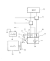
スタータ11は、いわゆるピニオン押し出し式スタータであり、モータ12と、このモータ12によって回転駆動されるピニオン13と、このピニオン13を押し出す電磁アクチュエータ14等を備えた構成となっている。ピニオン13は、軸方向に移動可能に設けられている。電磁アクチュエータ14には、プランジャ15と、このプランジャ15を駆動するソレノイド16が設けられ、プランジャ15の駆動力がレバー17等を介してピニオン13に伝達されるようになっている。
A first embodiment of the present invention will be described with reference to FIGS.
First, a schematic configuration of the engine start control system will be described with reference to FIG.
The
また、バッテリ18と電磁アクチュエータ14との間には、リレー19が設けられ、ECU20(エンジン制御回路)によってリレー19をオンして電磁アクチュエータ14の通電をオンすることで、プランジャ15をピニオン押出方向に移動させてピニオン13を押し出して、該ピニオン13をエンジン21のクランク軸22に連結されたリングギヤ23に噛み合わせるようになっている。
Further, a
更に、バッテリ18とモータ12との間には、機械式のリレー25と、このリレー25をオン/オフするためのスイッチング素子24が設けられ、ECU20によってスイッチング素子24をオンしてリレー25をオンすることで、モータ12の通電をオンしてピニオン13を回転駆動するようになっている。
Further, a
ECU20は、マイクロコンピュータを主体として構成され、内蔵されたROM(記憶媒体)に記憶された各種のエンジン制御プログラムを実行することで、エンジン運転状態に応じてエンジン21の燃料噴射量や点火時期を制御する。
The
また、ECU20は、図示しないエンジン自動停止始動制御ルーチンを実行することで、エンジン自動停止始動制御(いわゆるアイドルストップ制御)を実行する。このエンジン自動停止始動制御では、車両の走行中に運転者が減速操作(アクセル全閉、ブレーキ操作等)を行って減速要求が発生したときや、車両を停車させたときにエンジン自動停止要求が発生したと判断して、エンジン21の燃焼(燃料噴射及び/又は点火)を停止させてエンジン21を自動的に停止させる。その後、車両の走行中に減速要求が解除されたときや、車両の停止中に運転者が車両発進のための準備操作(ブレーキ解除、シフトレバー操作等)や発進操作(アクセル踏み込み等)を行ったときにエンジン再始動要求が発生したと判断して、エンジン21を再始動させる。
Further, the
その際、本実施例1では、ECU20により後述する図6のエンジン再始動制御ルーチンを実行することで、エンジン21の再始動制御を次のようにして行う。
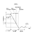
図2のタイムチャートに示すように、エンジン運転中にエンジン自動停止要求が発生すると、エンジン21の燃焼が停止されてエンジン21が自動停止される。
At this time, in the first embodiment, the
As shown in the time chart of FIG. 2, when an engine automatic stop request is generated during engine operation, combustion of the
(1) エンジン21の自動停止によりエンジン回転速度Ne が降下するエンジン回転降下期間中に、エンジン回転速度Ne が第1の回転速度N1 (例えば500rpm)よりも高い第1の回転速度領域(Ne >N1 )でエンジン再始動要求が発生したときには、スタータ11によるクランキングを行わなくてもエンジン21を再始動できると判断して、第1の再始動制御を実行する。この第1の再始動制御では、スタータ11によるクランキングを行わずに燃料噴射及び点火を再開してエンジン21を再始動させる。
(1) A first rotational speed region (Ne>) in which the engine rotational speed Ne is higher than the first rotational speed N1 (for example, 500 rpm) during the engine rotational speed decrease period in which the engine rotational speed Ne decreases due to the automatic stop of the
これにより、エンジン再始動要求が発生したときに、直ちにエンジン21の燃焼を再開してエンジン21を速やかに再始動させることができる。しかも、スタータ11によるクランキングを行わないため、スタータ11の電力消費量を0にすることができると共に、ピニオン13とリングギヤ23の回転速度の差が大きい状態でピニオン13をリングギヤ23に噛み合わせることを回避して、騒音の発生を防止することができる。
Thereby, when the engine restart request | requirement generate | occur | produces, the combustion of the
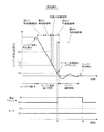
(2) エンジン21の自動停止によるエンジン回転降下期間中に、エンジン回転速度Ne が第1の回転速度N1 以下で第2の回転速度N2 (例えば350rpm)よりも高い第2の回転速度領域(N1 ≧Ne >N2 )でエンジン再始動要求が発生したときには、リングギヤ23の回転速度が比較的高いため、ピニオン13の回転速度をリングギヤ23の回転速度に同期させないと、ピニオン13をリングギヤ23にスムーズに噛み合わせることができないと判断して、第2の再始動制御を実行する。この第2の再始動制御では、モータ12によりピニオン13の回転速度をリングギヤ23の回転速度に同期させて両者の回転速度の差を小さくした後に、電磁アクチュエータ14によりピニオン13をリングギヤ23に噛み合わせてスタータ11によるクランキングを開始してエンジン21を再始動させる。
(2) During the engine rotation drop period due to the automatic stop of the
具体的には、図3に示すように、エンジン回転速度Ne が第2の回転速度領域でエンジン再始動要求が発生した時点t1 で、モータ12の通電をオンしてモータ12によりピニオン13を回転させ、リングギヤ23の回転速度とピニオン13の回転速度との回転速度差が±200rpmの範囲内になった時点t2 で、ピニオン13の回転速度がリングギヤ23の回転速度に同期したと判断して、電磁アクチュエータ14の通電をオンしてピニオン13をリングギヤ23に噛み合わせてスタータ11によるクランキングを開始してエンジン21を再始動させる。ここで、リングギヤ23の回転速度とピニオン13の回転速度との回転速度差における「回転速度差」とは、「クランク軸22に換算した回転速度差」を意味する(以下、同様)。
Specifically, as shown in FIG. 3, at the time t1 when an engine restart request is generated when the engine rotational speed Ne is in the second rotational speed region, the
このようにすれば、ピニオン13をリングギヤ23にスムーズに噛み合わせて騒音の発生を防止しながら、エンジン再始動要求からエンジン21を再始動させるまでの遅れを少なくすることができる。しかも、リングギヤ23の回転速度とピニオン13の回転速度との同期を判断する際の回転速度の検出精度をあまり高くする必要がないため、例えば、リングギヤ23の回転速度を精度良く検出できる高価なクランク角センサやピニオン13の回転速度を精度良く検出できる高価な回転速度センサを設ける必要がなく、近年の重要な技術的課題である低コスト化の要求を満たすことができる。
In this way, the delay from the engine restart request to the restart of the
本実施例1では、リングギヤ23の直径(歯先の外径)が300mmで、ピニオン13の直径(歯先の外径)が30mmである。この場合、例えば、リングギヤ23の回転速度が300rpmで、ピニオン13の回転速度が1000rpmのときに、リングギヤ23の回転速度とピニオン13の回転速度との回転速度差(クランク軸22に換算した回転速度差)が200rpmになる。このとき、リングギヤ23の直径が300mmで回転速度が300rpmであるため、リングギヤ23のピッチ円上(ピニオン13の歯車ところがり接触する仮想の円上)の周速度は約4.7m/秒となる。また、ピニオン13の直径が30mmで回転速度が1000rpmであるため、ピニオン13のピッチ円上(リングギヤ23の歯車ところがり接触する仮想の円上)の周速度は約1.6m/秒となる。これにより、リングギヤ23のピッチ円上の周速度とピニオン13のピッチ円上の周速度との周速度差は約3.1m/秒となる。従って、リングギヤ23の回転速度とピニオン13の回転速度との回転速度差が±200rpmの範囲内になるとは、リングギヤ23のピッチ円上の周速度とピニオン13のピッチ円上の周速度との周速度差が±3.1m/秒の範囲内になることである。
In the first embodiment, the diameter of the ring gear 23 (the outer diameter of the tooth tip) is 300 mm, and the diameter of the pinion 13 (the outer diameter of the tooth tip) is 30 mm. In this case, for example, when the rotational speed of the
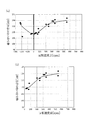
本発明者は、ピニオン13とリングギヤ23の噛み合い時の音圧を測定する試験を行ったので、その試験結果を図4に示す。この試験は、直径300mmのリングギヤ23と直径30mmのピニオン13を用いて、ピニオン13とリングギヤ23を噛み合わせる際のリングギヤ23の回転速度とピニオン13の回転速度との回転速度差を変化させて、回転速度差毎にピニオン13とリングギヤ23の噛み合い時の音圧を測定した。また、ピニオン13とリングギヤ23の噛み合い時の音圧は、噛み合い位置から15cm離れた位置にマイクを設置して測定した。
Since this inventor performed the test which measures the sound pressure at the time of mesh | engagement of the
図4に示す試験結果より、リングギヤ23の回転速度とピニオン13の回転速度との回転速度差が±250rpmの範囲内の場合、好ましくはリングギヤ23の回転速度とピニオン13の回転速度との回転速度差が±200rpmの範囲内(つまりリングギヤ23のピッチ円上の周速度とピニオン13のピッチ円上の周速度との周速度差が±3.1m/秒の範囲内)の場合に、ピニオン13とリングギヤ23の噛み合い時の音圧を十分に低減できることが確認された。
From the test results shown in FIG. 4, when the rotational speed difference between the rotational speed of the
尚、スタータ11に、エンジン回転方向においてモータ12からピニオン13へ動力を伝達するが、ピニオン13からモータ12へ動力を伝達しないワンウエイクラッチが設けられたシステムの場合には、第2の再始動制御の際に、リングギヤ23の回転速度がピニオン13の回転速度よりも高く且つリングギヤ23の回転速度とピニオン13の回転速度との回転速度差が所定値以下になったときにピニオン13の回転速度がリングギヤ23の回転速度に同期したと判断するようにしても良い。この場合、所定値は、300rpm以下の値(例えば200rpm)に設定すると良い。ここで、リングギヤ23の回転速度とピニオン13の回転速度との回転速度差が200rpm以下になるとは、リングギヤ23のピッチ円上の周速度とピニオン13のピッチ円上の周速度との周速度差が3.1m/秒以下になることである。
In the case of a system provided with a one-way clutch that transmits power to the
このようにすれば、ピニオン13の回転速度がリングギヤ23の回転速度に同期したと判断してピニオン13をリングギヤ23に噛み合わせる際に、リングギヤ23の回転速度がピニオン13の回転速度よりも高いときにピニオン13をリングギヤ23に噛み合わせるが、ワンウエイクラッチが空転してスタータ11に加わる衝撃を緩和することができ、その後、フリクションによるエンジン回転速度(リングギヤ23の回転速度)の低下とモータ12の回転速度(ピニオン13の回転速度)の上昇に伴って、リングギヤ23の回転速度とピニオン13の回転速度との回転速度差が0になったときに、ワンウエイクラッチがロックしてモータ12からピニオン13へ動力が伝達され始める。このような挙動により、ピニオン13をリングギヤ23に比較的スムーズに噛み合わせることができ、スタータ11の構成部品への衝撃も少なく、強度的に余裕を持たせることができる。
In this way, when it is determined that the rotation speed of the
(3) エンジン21の自動停止によるエンジン回転降下期間中に、エンジン回転速度Ne が第2の回転速度N2 よりも低い第3の回転速度N3 (例えば250rpm)以下の第3の回転速度領域(N3 ≧Ne )でエンジン再始動要求が発生したときには、リングギヤ23の回転速度が比較的低いため、ピニオン13の回転速度をリングギヤ23の回転速度に同期させなくても、ピニオン13をリングギヤ23にスムーズに噛み合わせることができると判断して、第3の再始動制御を実行する。この第3の再始動制御では、電磁アクチュエータ14によりピニオン13をリングギヤ23に噛み合わせた後又はその噛み合わせの途中にモータ12によりピニオン13を回転させてスタータ11によるクランキングを開始してエンジン21を再始動させる。
(3) A third rotation speed region (N3) in which the engine rotation speed Ne is lower than the second rotation speed N2 and lower than the third rotation speed N3 (for example, 250 rpm) during the engine rotation drop period due to the automatic stop of the
具体的には、図5に示すように、エンジン回転速度Ne が第3の回転速度領域でエンジン再始動要求が発生した時点t3 で、電磁アクチュエータ14の通電をオンしてピニオン13をリングギヤ23に噛み合わせ、ピニオン13とリングギヤ23の噛み合わせが完了した時点t4 又はその噛み合わせの途中の時点で、モータ12の通電をオンしてモータ12によりピニオン13を回転させてスタータ11によるクランキングを開始してエンジン21を再始動させる。
Specifically, as shown in FIG. 5, at a time t3 when an engine restart request is generated when the engine rotational speed Ne is in the third rotational speed region, the energization of the
このようにすれば、ピニオン13をリングギヤ23にスムーズに噛み合わせて騒音の発生を防止しながら、ピニオン13の回転速度をリングギヤ23の回転速度に同期させる処理を省略することができるため、その分、スタータ11によるクランキングの開始を早くしてエンジン21を速やかに再始動させることができると共に、スタータ11の電力消費量を低減することができる。
In this way, the process of synchronizing the rotation speed of the
(4) エンジン21の自動停止によるエンジン回転降下期間中に、エンジン回転速度Ne が第2の回転速度領域と第3の回転速度領域との間に設定された領域、つまり第2の回転速度N2 以下で第3の回転速度N3 よりも高い待機回転速度領域(N2 ≧Ne >N3 )でエンジン再始動要求が発生したときには、待機再始動制御を実行する。この待機再始動制御では、スタータ11によるクランキングを行わずに、その後、エンジン回転速度Ne が第3の回転速度N3 以下の第3の回転速度領域になったときに、第3の再始動制御と同じように電磁アクチュエータ14によりピニオン13をリングギヤ23に噛み合わせた後又はその噛み合わせの途中にモータ12によりピニオン13を回転させてスタータ11によるクランキングを開始してエンジン21を再始動させる。
(4) A region where the engine rotational speed Ne is set between the second rotational speed region and the third rotational speed region during the engine rotational drop period due to the automatic stop of the
これにより、第2の回転速度領域と第3の回転速度領域との間の領域(待機回転速度領域)でエンジン再始動要求が発生した場合でも、エンジン回転速度Ne の予測を必要とする複雑な再始動制御を行うことなく、スムーズにエンジン21の再始動を行うことができる。この場合、エンジン回転速度Ne が待機回転速度領域でエンジン再始動要求が発生しても、その後、エンジン回転速度Ne が第3の回転速度領域になってから、スタータ11によるクランキングを開始してエンジン21を再始動させることになるが、エンジン回転速度Ne が待機回転速度領域を通過する時間は比較的短いため、エンジン再始動要求からエンジン21を再始動させるまでの遅れを許容範囲内に抑えることができる。
As a result, even when an engine restart request is generated in an area between the second rotation speed area and the third rotation speed area (standby rotation speed area), a complicated operation that requires prediction of the engine rotation speed Ne is required. The
尚、エンジン21の再始動制御の際に、エンジン回転速度Ne (リングギヤ23の回転速度)は、例えば、エンジン自動停止要求の発生(又はエンジン21の燃焼停止)からの経過時間をパラメータとするエンジン回転速度Ne のマップを参照して、エンジン自動停止要求の発生(又はエンジン21の燃焼停止)からの経過時間に応じたエンジン回転速度Ne を推定(算出)する。エンジン回転速度Ne のマップは、予め試験データや設計データ等に基づいて作成され、ECU20のROMに記憶されている。一般に、エンジン自動停止要求が発生してエンジン21の燃焼が停止されてからの時間経過に伴ってエンジン回転速度Ne が低下するため、エンジン自動停止要求の発生(又はエンジン21の燃焼停止)からの経過時間からエンジン回転速度Ne を推定することができる。
In the restart control of the
また、ピニオン13の回転速度は、例えば、モータ12の通電時間(通電開始後の経過時間)と通電電流(例えばデューティ比)とをパラメータとするピニオン13の回転速度のマップを参照して、モータ12の通電時間と通電電流とに応じたピニオン13の回転速度を推定(算出)する。ピニオン13の回転速度のマップは、予め試験データや設計データ等に基づいて作成され、ECU20のROMに記憶されている。一般に、モータ12の通電開始後の時間経過に伴ってモータ12の回転速度が上昇してピニオン13の回転速度が上昇し、その際、モータ12の通電電流が大きいほどモータ12の回転速度が速くなってピニオン13の回転速度が速くなるため、モータ12の通電時間や通電電流からピニオン13の回転速度を推定することができる。
The rotation speed of the
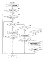
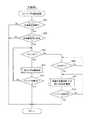
以上説明した本実施例1のエンジン21の再始動制御は、ECU20によって図6のエンジン再始動制御ルーチンに従って実行される。以下、図6のエンジン再始動制御ルーチンの処理内容を説明する。
The restart control of the
図6に示すエンジン再始動制御ルーチンは、ECU20の電源オン中に所定周期で繰り返し実行される。本ルーチンが起動されると、まず、ステップ101で、エンジン自動停止制御中(例えば、エンジン21の燃焼停止から再始動制御が開始されるまでの期間)であるか否かを判定し、エンジン自動停止制御中ではないと判定されれば、ステップ102以降の再始動制御に関する処理を行うことなく、本ルーチンを終了する。
The engine restart control routine shown in FIG. 6 is repeatedly executed at a predetermined cycle while the
一方、上記ステップ101で、エンジン自動停止制御中であると判定された場合には、ステップ102以降の再始動制御に関する処理を次のようにして実行する。まず、ステップ102で、エンジン再始動要求が発生したか否かを判定し、エンジン再始動要求が発生したと判定された時点で、ステップ103に進み、現在のエンジン回転速度Ne が第1の回転速度N1 よりも高いか否かによって、エンジン回転速度Ne が第1の回転速度領域(Ne >N1 )であるか否かを判定する。
On the other hand, if it is determined in
ここで、第1の回転速度N1 は、例えば300〜700rpmの範囲内(本実施例1では500rpm)に設定されている。エンジン回転降下期間中に、エンジン回転速度Ne が第1の回転速度N1 (300〜700rpm)よりも高いときには、スタータ11によるクランキングを行わなくても燃焼(燃料噴射・点火)を再開するだけでエンジン21を再始動できるため、第1の回転速度N1 を300〜700rpmの範囲内に設定すれば、第1の回転速度N1 (300〜700rpm)よりも高い第1の回転速度領域が、スタータ11によるクランキングを行わずに燃料噴射及び点火を再開してエンジン21を再始動できる領域となる。
Here, the first rotation speed N1 is set, for example, within a range of 300 to 700 rpm (500 rpm in the first embodiment). If the engine rotation speed Ne is higher than the first rotation speed N1 (300 to 700 rpm) during the engine rotation descent period, combustion (fuel injection / ignition) is simply resumed without cranking by the
エンジン再始動要求が発生したと判定された時点において、ステップ103で、エンジン回転速度Ne が第1の回転速度N1 よりも高いと判定された場合(つまりエンジン回転速度Ne が第1の回転速度領域でエンジン再始動要求が発生した場合)には、スタータ11によるクランキングを行わなくてもエンジン21を再始動できると判断して、ステップ104に進み、第1の再始動制御を実行する。この第1の再始動制御では、スタータ11によるクランキングを行わずに燃料噴射及び点火を再開してエンジン21を再始動させる。このステップ104の処理が特許請求の範囲でいう第1の再始動制御手段としての役割を果たす。
When it is determined that an engine restart request has occurred, if it is determined in
この後、ステップ105に進み、エンジン21の始動が完了したか否かを、例えばエンジン回転速度Ne が始動完了判定値を越えたか否かによって判定し、エンジン21の始動が完了していないと判定された場合には、上記ステップ103に戻り、エンジン回転速度Ne が第1の回転速度領域であれば、第1の再始動制御を継続する(ステップ103、104)。その後、ステップ105で、エンジン21の始動が完了したと判定されれば、本ルーチンを終了する。
Thereafter, the routine proceeds to step 105, where it is determined whether or not the
一方、上記ステップ103で、現在のエンジン回転速度Ne が第1の回転速度N1 以下であると判定された場合には、ステップ106に進み、現在のエンジン回転速度Ne が第2の回転速度N2 よりも高いか否かによって、エンジン回転速度Ne が第2の回転速度領域(N1 ≧Ne >N2 )であるか否かを判定する。ここで、第2の回転速度N2 は、第3の回転速度N3 よりも例えば50〜150rpm高い回転速度(本実施例1では350rpm)に設定されている。
On the other hand, if it is determined in
エンジン再始動要求が発生したと判定された時点において、ステップ106で、エンジン回転速度Ne が第2の回転速度N2 よりも高いと判定された場合(つまりエンジン回転速度Ne が第2の回転速度領域でエンジン再始動要求が発生した場合)には、リングギヤ23の回転速度が比較的高いため、ピニオン13の回転速度をリングギヤ23の回転速度に同期させないと、ピニオン13をリングギヤ23にスムーズに噛み合わせることができないと判断して、ステップ107に進み、第2の再始動制御を実行する。この第2の再始動制御では、モータ12によりピニオン13の回転速度をリングギヤ23の回転速度に同期させて両者の回転速度の差を小さくした後に電磁アクチュエータ14によりピニオン13をリングギヤ23に噛み合わせてスタータ11によるクランキングを開始してエンジン21を再始動させる。このステップ107の処理が特許請求の範囲でいう第2の再始動制御手段としての役割を果たす。
When it is determined that an engine restart request has occurred, if it is determined in
この後、ステップ108に進み、エンジン21の始動が完了したか否かを判定し、エンジン21の始動が完了したと判定されれば、本ルーチンを終了するが、エンジン21の始動が完了していないと判定されれば、ステップ110に進む。
Thereafter, the routine proceeds to step 108, where it is determined whether or not the
一方、上記ステップ106で、現在のエンジン回転速度Ne が第2の回転速度N2 以下であると判定された場合には、ステップ109に進み、現在のエンジン回転速度Ne が第3の回転速度N3 以下であるか否かによって、エンジン回転速度Ne が第3の回転速度領域(N3 ≧Ne )であるか待機回転速度領域(N2 ≧Ne >N3 )であるかを判定する。
On the other hand, if it is determined in
ここで、第3の回転速度N3 は、例えば50〜450rpmの範囲内(本実施例1では250rpm)に設定されている。エンジン回転降下期間中に、エンジン回転速度Ne が第3の回転速度N2 (50〜450rpm)以下に低下すれば、ピニオン13の回転速度をリングギヤ23の回転速度に同期させなくても、ピニオン13をリングギヤ23にスムーズに噛み合わせることができるため、第3の回転速度N3 を50〜450rpmの範囲内に設定すれば、第3の回転速度N3 (50〜450rpm)以下の第3の回転速度領域が、ピニオン13の回転速度をリングギヤ23の回転速度に同期させなくても、ピニオン13をリングギヤ23にスムーズに噛み合わせることができる領域となる。
Here, the third rotation speed N3 is set, for example, within a range of 50 to 450 rpm (250 rpm in the first embodiment). If the engine rotational speed Ne decreases to the third rotational speed N2 (50 to 450 rpm) or less during the engine rotational drop period, the
エンジン再始動要求が発生したと判定された時点において、ステップ109で、エンジン回転速度Ne が第3の回転速度N3 以下であると判定された場合(つまりエンジン回転速度Ne が第3の回転速度領域でエンジン再始動要求が発生した場合)には、リングギヤ23の回転速度が比較的低いため、ピニオン13の回転速度をリングギヤ23の回転速度に同期させなくても、ピニオン13をリングギヤ23にスムーズに噛み合わせることができると判断して、ステップ110に進み、第3の再始動制御を実行する。この第3の再始動制御では、電磁アクチュエータ14によりピニオン13をリングギヤ23に噛み合わせた後又はその噛み合わせの途中にモータ12によりピニオン13を回転させてスタータ11によるクランキングを開始してエンジン21を再始動させる。このステップ110の処理が特許請求の範囲でいう第3の再始動制御手段としての役割を果たす。
When it is determined that an engine restart request has occurred, if it is determined in
これに対して、エンジン再始動要求が発生したと判定された時点において、上記ステップ109で、エンジン回転速度Ne が第3の回転速度N3 よりも高いと判定された場合(つまりエンジン回転速度Ne が待機回転速度領域でエンジン再始動要求が発生した場合)には、スタータ11によるクランキングを行わずに、その後、ステップ109で、エンジン回転速度Ne が第3の回転速度N3 以下になったと判定されたとき(つまりエンジン回転速度Ne が第3の回転速度領域まで低下したとき)に、ステップ110に進み、待機再始動制御を実行する。この待機再始動制御では、第3の再始動制御と同じように電磁アクチュエータ14によりピニオン13をリングギヤ23に噛み合わせた後又はその噛み合わせの途中にモータ12によりピニオン13を回転させてスタータ11によるクランキングを開始してエンジン21を再始動させる。このステップ110の処理が特許請求の範囲でいう待機再始動制御手段としての役割を果たす。
On the other hand, when it is determined that an engine restart request has occurred, if it is determined in
この後、ステップ111に進み、エンジン21の始動が完了したか否かを判定し、エンジン21の始動が完了していないと判定された場合には、上記ステップ110に戻り、第3の再始動制御又は待機再始動制御を継続する。その後、ステップ111で、エンジン21の始動が完了したと判定されれば、本ルーチンを終了する。
Thereafter, the process proceeds to step 111, where it is determined whether or not the
以上説明した本実施例1では、エンジン21の自動停止によるエンジン回転降下期間中に、エンジン回転速度Ne が第1の回転速度領域でエンジン再始動要求が発生したときには、スタータ11によるクランキングを行わずに燃料噴射及び点火を再開してエンジン21を再始動させる第1の再始動制御を実行し、エンジン回転速度Ne が第2の回転速度領域でエンジン再始動要求が発生したときには、ピニオン13の回転速度をリングギヤ23の回転速度に同期させた後にピニオン13をリングギヤ23に噛み合わせてスタータ11によるクランキングを開始してエンジン21を再始動させる第2の再始動制御を実行する。また、エンジン回転速度Ne が第3の回転速度領域でエンジン再始動要求が発生したときには、ピニオン13をリングギヤ23に噛み合わせた後又はその噛み合わせの途中にピニオン13を回転させてスタータ11によるクランキングを開始してエンジン21を再始動させる第3の再始動制御を実行し、エンジン回転速度Ne が第2の回転速度領域と第3の回転速度領域との間に設定された待機回転速度領域でエンジン再始動要求が発生したときには、スタータ11によるクランキングを行わずに、その後、エンジン回転速度Ne が第3の回転速度領域になったときに、ピニオン13をリングギヤ23に噛み合わせた後又はその噛み合わせの途中にピニオン13を回転させてスタータ11によるクランキングを開始してエンジン21を再始動させる待機再始動制御を実行する。これにより、エンジン回転降下期間中にエンジン再始動要求が発生したときに、そのときのエンジン回転速度Ne に応じた適正なエンジン再始動制御を行うことができて、スムーズにエンジン21の再始動を行うことができ、エンジン21の再始動の遅れや騒音の発生を防止できると共に、スタータ11の電力消費量を低減することができる。
In the first embodiment described above, cranking is performed by the
また、本実施例1では、エンジン再始動制御の際に、エンジン自動停止要求の発生(又はエンジン21の燃焼停止)からの経過時間に基づいてエンジン回転速度を推定するようにしたので、例えば、エンジン回転降下期間のエンジン回転速度を精度良く検出できる高価なクランク角センサを設ける必要がなく、更に、モータ12の通電時間と通電電流とに基づいてピニオン13の回転速度を推定するようにしたので、モータ12の回転速度(ピニオン13の回転速度)を検出するセンサを省略した構成にすることができ、近年の重要な技術的課題である低コスト化の要求を満たすことができる。
In the first embodiment, when the engine restart control is performed, the engine rotation speed is estimated based on the elapsed time from the generation of the engine automatic stop request (or the combustion stop of the engine 21). Since it is not necessary to provide an expensive crank angle sensor that can accurately detect the engine speed during the engine speed drop period, the rotation speed of the
尚、上記実施例1では、第1〜第3の再始動制御と待機再始動制御を実行可能な構成としたが、第1の再始動制御を実行する機能を省略して、第2及び第3の再始動制御と待機再始動制御を実行可能な構成としても良い。 In the first embodiment, the first to third restart controls and the standby restart control can be executed. However, the function of executing the first restart control is omitted, and the second and second restart controls are executed. 3 may be configured to execute the restart control 3 and the standby restart control.
次に、図7及び図8を用いて本発明の実施例2を説明する。但し、前記実施例1と実質的に同一部分については説明を省略又は簡略化し、主として前記実施例1と異なる部分について説明する。
Next,
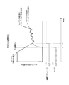
本実施例2では、ECU20により後述する図8のエンジン再始動制御ルーチンを実行することで、図7のタイムチャートに示すように、エンジン21の自動停止によるエンジン回転降下期間中に、エンジン再始動要求が発生せずにエンジン回転速度Ne が第4の回転速度N4 (エンジン回転速度Ne が0となる直前の回転速度であり、例えば100rpm)まで低下したときには、第4の再始動制御を実行する。この第4の再始動制御では、エンジン回転速度Ne が第4の回転速度N4 まで低下したときに、電磁アクチュエータ14によりピニオン13をリングギヤ23に噛み合わせて、その後、エンジン再始動要求が発生したときに、モータ12によりピニオン13を回転させてスタータ11によるクランキングを開始してエンジン21を再始動させるようにしている。
In the second embodiment, the engine restart control routine of FIG. 8 to be described later is executed by the
具体的には、エンジン回転速度Ne が第4の回転速度N4 まで低下した時点t5 で、電磁アクチュエータ14によりピニオン13をリングギヤ23に噛み合わせるように電磁アクチュエータ14の通電をオンし、該電磁アクチュエータ14の通電をオンしてから所定時間(例えばピニオン13とリングギヤ23との噛合が完了するのに必要な時間)が経過した時点t6 で、電磁アクチュエータ14の通電をオフしてもピニオン13とリングギヤ23とを噛合状態に保持できると判断して、電磁アクチュエータ14の通電をオフにする。その後、エンジン再始動要求が発生した時点で、電磁アクチュエータ14の通電をオンすると共に、モータ12の通電をオンしてピニオン13を回転させてスタータ11によるクランキングを開始してエンジン21を再始動させる。
Specifically, at the time t5 when the engine rotational speed Ne is reduced to the fourth rotational speed N4, the
このようにすれば、エンジン回転が停止する間際のエンジン揺動期間(エンジン21の逆回転と正回転を交互に繰り返す期間)よりも前に、ピニオン13をリングギヤ23に噛み合わせておくことができるので、エンジン揺動期間中にピニオン13をリングギヤ23に噛み合わせることを回避して、スタータ11の破損や騒音の発生を防止することができる。そして、エンジン回転速度Ne が第4の回転速度N4 以下に低下した後にエンジン再始動要求が発生したときに、その時点で、スタータ11によるクランキングを開始してエンジン21を速やかに再始動させることができる。
In this way, the
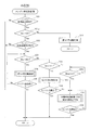
以下、本実施例2でECU20が実行する図8のエンジン再始動制御ルーチンの処理内容を説明する。本ルーチンでは、まず、ステップ101で、エンジン自動停止制御中であるか否かを判定し、エンジン自動停止制御中であると判定されれば、ステップ101aに進み、エンジン回転速度Ne が第4の回転速度N4 よりも高いか否かを判定する。ここで、第4の回転速度N4 は、エンジン回転速度Ne が0となる直前の回転速度であり、例えば100rpmに設定されている。
Hereinafter, the processing content of the engine restart control routine of FIG. 8 executed by the
このステップ101aで、エンジン回転速度Ne が第4の回転速度N4 よりも高いと判定された場合には、ステップ102に進み、エンジン再始動要求が発生したか否かを判定する。
If it is determined in
この後、エンジン再始動要求が発生したと判定された時点において、ステップ103で、エンジン回転速度Ne が第1の回転速度N1 よりも高いと判定された場合(つまりエンジン回転速度Ne が第1の回転速度領域でエンジン再始動要求が発生した場合)には、第1の再始動制御を実行してエンジン21を再始動させる(ステップ104、105)。
Thereafter, when it is determined that an engine restart request has occurred, if it is determined in
また、エンジン再始動要求が発生したと判定された時点において、ステップ106で、エンジン回転速度Ne が第2の回転速度N2 よりも高いと判定された場合(つまりエンジン回転速度Ne が第2の回転速度領域でエンジン再始動要求が発生した場合)には、第2の再始動制御を実行してエンジン21を再始動させる(ステップ107、108)。
When it is determined that an engine restart request has been generated, if it is determined in
また、エンジン再始動要求が発生したと判定された時点において、ステップ109で、エンジン回転速度Ne が第3の回転速度N3 以下であると判定された場合(つまりエンジン回転速度Ne が第3の回転速度領域でエンジン再始動要求が発生した場合)には、第3の再始動制御を実行してエンジン21を再始動させる(ステップ110、111)。
Further, when it is determined that an engine restart request has occurred, if it is determined in
一方、エンジン再始動要求が発生したと判定された時点において、上記ステップ109で、エンジン回転速度Ne が第3の回転速度N3 よりも高いと判定された場合(つまりエンジン回転速度Ne が待機回転速度領域でエンジン再始動要求が発生した場合)には、スタータ11によるクランキングを行わずに、その後、ステップ109でエンジン回転速度Ne が第3の回転速度N3 以下になったと判定されたとき(つまりエンジン回転速度Ne が第3の回転速度領域まで低下したとき)に、待機再始動制御を実行してエンジン21を再始動させる(ステップ110、111)。
On the other hand, when it is determined that an engine restart request has occurred, if it is determined in
これに対して、上記ステップ101aで、エンジン回転速度Ne が第4の回転速度N4 以下であると判定された場合(つまりエンジン再始動要求が発生せずにエンジン回転速度Ne が第4の回転速度N4 以下に低下した場合)には、ステップ112に進み、第4の再始動制御を実行する。この第4の再始動制御では、エンジン回転速度Ne が第4の回転速度N4 まで低下したときに、電磁アクチュエータ14によりピニオン13をリングギヤ23に噛み合わせて、その後、エンジン再始動要求が発生したときに、モータ12によりピニオン13を回転させてスタータ11によるクランキングを開始してエンジン21を再始動させる。
On the other hand, when it is determined in
以上説明した本実施例2では、第4の再始動制御により、エンジン21の自動停止によるエンジン回転降下期間中にエンジン再始動要求が発生せずにエンジン回転速度Ne が第4の回転速度N4 まで低下したときに、ピニオン13をリングギヤ23に噛み合わせるようにしたので、エンジン回転が停止する間際のエンジン揺動期間(エンジン21の逆回転と正回転を交互に繰り返す期間)よりも前に、ピニオン13をリングギヤ23に噛み合わせておくことができ、エンジン揺動期間中にピニオン13をリングギヤ23に噛み合わせることを回避して、スタータ11の破損や騒音の発生を防止できる。そして、その後、エンジン再始動要求が発生したときに、ピニオン13を回転させてスタータ11によるクランキングを開始してエンジン21を再始動させるようにしたので、エンジン21を速やかに再始動させることができる。
In the second embodiment described above, the engine speed Ne reaches the fourth rotational speed N4 by the fourth restart control without generating an engine restart request during the engine rotational drop period due to the automatic stop of the
また、本実施例2では、第4の再始動制御により、エンジン回転速度Ne が第4の回転速度N4 まで低下した時点で電磁アクチュエータ14の通電をオンし、該電磁アクチュエータ14の通電をオンしてから所定時間が経過した時点で電磁アクチュエータ14の通電をオフにするようにしたので、その後、エンジン再始動要求が発生してスタータ11によるクランキングを開始するまで、電磁アクチュエータ14の通電をオフに維持することができ、スタータ11の電力消費量を低減することができる。
In the second embodiment, energization of the
尚、上記実施例2では、第4の再始動制御の際に、電磁アクチュエータ14の通電をオンした後に、電磁アクチュエータ14の通電をオンしてから所定時間が経過した時点で電磁アクチュエータ14の通電をオフするようにしたが、例えば、ピニオン13とリングギヤ23との噛合を確認可能なセンサを設け、このセンサで実際にピニオン13とリングギヤ23との噛合を確認した時点で電磁アクチュエータ14の通電をオフするようにしても良い。
In the second embodiment, when the
また、上記実施例2では、第1〜第4の再始動制御と待機再始動制御を実行可能な構成としたが、第1の再始動制御を実行する機能を省略して、第2〜第4の再始動制御と待機再始動制御を実行可能な構成としても良い。 Moreover, in the said Example 2, although it was set as the structure which can perform 1st-4th restart control and standby restart control, the function which performs 1st restart control is abbreviate | omitted, and 2nd-2nd It is good also as a structure which can perform 4 restart control and standby restart control.
次に、図10及び図11を用いて本発明の実施例3を説明する。但し、前記実施例1と実質的に同一部分については説明を省略又は簡略化し、主として前記実施例1と異なる部分について説明する。 Next, Embodiment 3 of the present invention will be described with reference to FIGS. However, description of substantially the same parts as those in the first embodiment will be omitted or simplified, and different parts from the first embodiment will be mainly described.
本実施例3では、ECU20により後述する図11のエンジン再始動制御ルーチンを実行することで、図10のタイムチャートに示すように、エンジン21の自動停止によるエンジン回転降下期間中に、エンジン回転速度Ne が第1の回転速度領域と第2の回転速度領域との間に設定された領域、つまり第1の回転速度N1 以下で第2の回転速度N2 (例えば400rpm)よりも高い待機回転速度領域(N1 ≧Ne >N2 )でエンジン再始動要求が発生したときには、待機再始動制御を実行する。この待機再始動制御では、スタータ11によるクランキングを行わずに、その後、エンジン回転速度Ne が第2の回転速度N2 以下で第3の回転速度N3 よりも高い第2の回転速度領域(N2 ≧Ne >N3 )になったときに、第2の再始動制御と同じようにモータ12によりピニオン13の回転速度をリングギヤ23の回転速度に同期させて両者の回転速度の差を小さくした後に、電磁アクチュエータ14によりピニオン13をリングギヤ23に噛み合わせてスタータ11によるクランキングを開始してエンジン21を再始動させる。
In the third embodiment, the engine restart control routine of FIG. 11 to be described later is executed by the
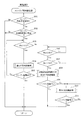
以下、本実施例3でECU20が実行する図11のエンジン再始動制御ルーチンの処理内容を説明する。本ルーチンでは、まず、ステップ201で、エンジン自動停止制御中であるか否かを判定し、エンジン自動停止制御中であると判定されれば、ステップ202に進み、エンジン再始動要求が発生したか否かを判定し、エンジン再始動要求が発生したと判定された時点で、ステップ203に進み、現在のエンジン回転速度Ne が第1の回転速度N1 よりも高いか否かを判定する。
Hereinafter, the processing content of the engine restart control routine of FIG. 11 executed by the
エンジン再始動要求が発生したと判定された時点において、ステップ203で、エンジン回転速度Ne が第1の回転速度N1 よりも高いと判定された場合(つまりエンジン回転速度Ne が第1の回転速度領域でエンジン再始動要求が発生した場合)には、第1の再始動制御を実行して、スタータ11によるクランキングを行わずに燃料噴射及び点火を再開してエンジン21を再始動させる(ステップ204、205)。
When it is determined that an engine restart request has occurred, if it is determined in
一方、上記ステップ203で、現在のエンジン回転速度Ne が第1の回転速度N1 以下であると判定された場合には、ステップ206に進み、現在のエンジン回転速度Ne が第2の回転速度N2 以下であるか否かを判定し、第2の回転速度N2 以下であると判定されれば、ステップ207に進み、現在のエンジン回転速度Ne が第3の回転速度N3 よりも高いか否かを判定する。
On the other hand, if it is determined in
エンジン再始動要求が発生したと判定された時点において、上記ステップ206でエンジン回転速度Ne が第2の回転速度N2 以下であると判定され、且つ、上記ステップ207でエンジン回転速度Ne が第3の回転速度N3 よりも高いと判定された場合(つまりエンジン回転速度Ne が第2の回転速度領域でエンジン再始動要求が発生した場合)には、第2の再始動制御を実行して、モータ12によりピニオン13の回転速度をリングギヤ23の回転速度に同期させて両者の回転速度の差を小さくした後に電磁アクチュエータ14によりピニオン13をリングギヤ23に噛み合わせてスタータ11によるクランキングを開始してエンジン21を再始動させる(ステップ208、209)。
When it is determined that an engine restart request has been generated, it is determined in
これに対して、エンジン再始動要求が発生したと判定された時点において、上記ステップ206で、エンジン回転速度Ne が第2の回転速度N2 よりも高いと判定された場合(つまりエンジン回転速度Ne が待機回転速度領域でエンジン再始動要求が発生した場合)には、スタータ11によるクランキングを行わずに、その後、ステップ206で、エンジン回転速度Ne が第2の回転速度N2 以下になったと判定されたとき(つまりエンジン回転速度Ne が第2の回転速度領域まで低下したとき)に、待機再始動制御を実行して、第2の再始動制御と同じようにモータ12によりピニオン13の回転速度をリングギヤ23の回転速度に同期させて両者の回転速度の差を小さくした後に電磁アクチュエータ14によりピニオン13をリングギヤ23に噛み合わせてスタータ11によるクランキングを開始してエンジン21を再始動させる(ステップ208、209)。
On the other hand, when it is determined that an engine restart request has occurred, if it is determined in
一方、エンジン再始動要求が発生したと判定された時点において、上記ステップ207で、エンジン回転速度Ne が第3の回転速度N3 以下であると判定された場合(つまりエンジン回転速度Ne が第3の回転速度領域でエンジン再始動要求が発生した場合)には、第3の再始動制御を実行して、電磁アクチュエータ14によりピニオン13をリングギヤ23に噛み合わせた後又はその噛み合わせの途中にモータ12によりピニオン13を回転させてスタータ11によるクランキングを開始してエンジン21を再始動させる(210、211)。
On the other hand, when it is determined that the engine restart request has occurred, if it is determined in
以上説明した本実施例3では、第1の回転速度領域と第2の回転速度領域との間に待機回転速度領域を設定し、この待機回転速度領域でエンジン再始動要求が発生したときには、スタータ11によるクランキングを行わずに、その後、エンジン回転速度Ne が第2の回転速度領域になったときに、第2の再始動制御と同じようにモータ12によりピニオン13の回転速度をリングギヤ23の回転速度に同期させて両者の回転速度の差を小さくした後に電磁アクチュエータ14によりピニオン13をリングギヤ23に噛み合わせてスタータ11によるクランキングを開始してエンジン21を再始動させる待機再始動制御を実行するようにしたので、第1の回転速度領域と第2の回転速度領域との間の領域(待機回転速度領域)でエンジン再始動要求が発生した場合でも、エンジン回転速度Ne の予測を必要とする複雑な再始動制御を行うことなく、スムーズにエンジン21の再始動を行うことができる。この場合、エンジン回転速度Ne が待機回転速度領域でエンジン再始動要求が発生しても、その後、エンジン回転速度Ne が第2の回転速度領域になってから、スタータ11によるクランキングを開始してエンジン21を再始動させることになるが、エンジン回転速度Ne が待機回転速度領域を通過する時間は比較的短いため、エンジン再始動要求からエンジン21を再始動させるまでの遅れを許容範囲内に抑えることができる。
In the third embodiment described above, a standby rotational speed region is set between the first rotational speed region and the second rotational speed region, and when an engine restart request is generated in this standby rotational speed region, the
尚、上記実施例3では、第1〜第3の再始動制御と待機再始動制御を実行可能な構成としたが、更に、上記実施例2で説明した第4の再始動制御を実行可能な構成としても良い。 In the third embodiment, the first to third restart controls and the standby restart control can be executed. However, the fourth restart control described in the second embodiment can be executed. It is good also as a structure.
次に、図12及び図13を用いて本発明の実施例4を説明する。但し、前記実施例1と実質的に同一部分については説明を省略又は簡略化し、主として前記実施例1と異なる部分について説明する。 Next, Embodiment 4 of the present invention will be described with reference to FIGS. However, description of substantially the same parts as those in the first embodiment will be omitted or simplified, and different parts from the first embodiment will be mainly described.
本実施例4では、ECU20により後述する図13のエンジン再始動制御ルーチンを実行することで、図12のタイムチャートに示すように、エンジン21の自動停止によるエンジン回転降下期間中に、エンジン回転速度Ne が第1の回転速度領域と第3の回転速度領域との間に設定された領域、つまり第1の回転速度N1 以下で第3の回転速度N3 よりも高い待機回転速度領域(N1 ≧Ne >N3 )でエンジン再始動要求が発生したときには、待機再始動制御を実行する。この待機再始動制御では、スタータ11によるクランキングを行わずに、その後、エンジン回転速度Ne が第3の回転速度N3 以下の第3の回転速度領域になったときに、第3の再始動制御と同じように電磁アクチュエータ14によりピニオン13をリングギヤ23に噛み合わせた後又はその噛み合わせの途中にモータ12によりピニオン13を回転させてスタータ11によるクランキングを開始してエンジン21を再始動させる。
In the fourth embodiment, the engine restart control routine of FIG. 13 described later is executed by the
以下、本実施例4でECU20が実行する図13のエンジン再始動制御ルーチンの処理内容を説明する。本ルーチンでは、まず、ステップ301で、エンジン自動停止制御中であるか否かを判定し、エンジン自動停止制御中であると判定されれば、ステップ302に進み、エンジン再始動要求が発生したか否かを判定し、エンジン再始動要求が発生したと判定された時点で、ステップ303に進み、現在のエンジン回転速度Ne が第1の回転速度N1 よりも高いか否かを判定する。
Hereinafter, the processing content of the engine restart control routine of FIG. 13 executed by the
エンジン再始動要求が発生したと判定された時点において、ステップ303で、エンジン回転速度Ne が第1の回転速度N1 よりも高いと判定された場合(つまりエンジン回転速度Ne が第1の回転速度領域でエンジン再始動要求が発生した場合)には、第1の再始動制御を実行して、スタータ11によるクランキングを行わずに燃料噴射及び点火を再開してエンジン21を再始動させる(ステップ304、305)。
When it is determined that an engine restart request has occurred, if it is determined in
一方、上記ステップ303で、現在のエンジン回転速度Ne が第1の回転速度N1 以下であると判定された場合には、ステップ306に進み、現在のエンジン回転速度Ne が第3の回転速度N3 以下であるか否かを判定する。
On the other hand, if it is determined in
エンジン再始動要求が発生したと判定された時点において、上記ステップ306で、エンジン回転速度Ne が第3の回転速度N3 以下であると判定された場合(つまりエンジン回転速度Ne が第3の回転速度領域でエンジン再始動要求が発生した場合)には、第3の再始動制御を実行して、電磁アクチュエータ14によりピニオン13をリングギヤ23に噛み合わせた後又はその噛み合わせの途中にモータ12によりピニオン13を回転させてスタータ11によるクランキングを開始してエンジン21を再始動させる(307、308)。
When it is determined that an engine restart request has been generated, if it is determined in
これに対して、エンジン再始動要求が発生したと判定された時点において、上記ステップ306で、エンジン回転速度Ne が第3の回転速度N3 よりも高いと判定された場合(つまりエンジン回転速度Ne が待機回転速度領域でエンジン再始動要求が発生した場合)には、スタータ11によるクランキングを行わずに、その後、ステップ306で、エンジン回転速度Ne が第3の回転速度N3 以下になったと判定されたとき(つまりエンジン回転速度Ne が第3の回転速度領域まで低下したとき)に、待機再始動制御を実行して、第3の再始動制御と同じように電磁アクチュエータ14によりピニオン13をリングギヤ23に噛み合わせた後又はその噛み合わせの途中にモータ12によりピニオン13を回転させてスタータ11によるクランキングを開始してエンジン21を再始動させる(307、308)。
On the other hand, when it is determined that an engine restart request has occurred, if it is determined in
以上説明した本実施例4では、第1の回転速度領域と第3の回転速度領域との間に待機回転速度領域を設定し、この待機回転速度領域でエンジン再始動要求が発生したときには、スタータ11によるクランキングを行わずに、その後、エンジン回転速度Ne が第3の回転速度領域になったときに、第3の再始動制御と同じように電磁アクチュエータ14によりピニオン13をリングギヤ23に噛み合わせた後又はその噛み合わせの途中にモータ12によりピニオン13を回転させてスタータ11によるクランキングを開始してエンジン21を再始動させる待機再始動制御を実行するようにしたので、第1の回転速度領域と第3の回転速度領域との間の領域(待機回転速度領域)でエンジン再始動要求が発生した場合でも、エンジン回転速度Ne の予測を必要とする複雑な再始動制御を行うことなく、スムーズにエンジン21の再始動を行うことができる。この場合、エンジン回転速度Ne が待機回転速度領域でエンジン再始動要求が発生しても、その後、エンジン回転速度Ne が第3の回転速度領域になってから、スタータ11によるクランキングを開始してエンジン21を再始動させることになるが、エンジン回転速度Ne が待機回転速度領域を通過する時間は比較的短いため、エンジン再始動要求からエンジン21を再始動させるまでの遅れを許容範囲内に抑えることができる。
In the fourth embodiment described above, a standby rotational speed region is set between the first rotational speed region and the third rotational speed region, and when an engine restart request is generated in this standby rotational speed region, the
尚、上記実施例4では、第1及び第3の再始動制御と待機再始動制御を実行可能な構成としたが、更に、上記実施例2で説明した第4の再始動制御を実行可能な構成としても良い。 In the fourth embodiment, the first and third restart controls and the standby restart control can be executed. However, the fourth restart control described in the second embodiment can be executed. It is good also as a structure.
また、上記各実施例1〜4では、エンジン21の再始動制御の際に、エンジン自動停止要求の発生(又はエンジン21の燃焼停止)からの経過時間に基づいてエンジン回転速度Ne を推定(算出)し、モータ12の通電時間と通電電流に基づいてピニオン13の回転速度を推定(算出)するようにしたが、これに限定されず、例えば、クランク角センサの出力信号に基づいてエンジン回転速度を検出するようにしたり、モータの回転速度(ピニオン13の回転速度)を検出するセンサの出力信号に基づいてピニオン13の回転速度を検出するようにしても良い。
In the first to fourth embodiments, when the
次に、図14乃至図16を用いて本発明の実施例5を説明する。
本実施例5では、上記各実施例1〜4のいずれかのエンジン21の再始動制御を実行するシステムにおいて、ECU20は、エンジン21の自動停止によりエンジン回転速度が降下する軌道(以下「エンジン回転降下軌道」という)を予測する回転降下軌道予測手段として機能し、更に、そのエンジン回転降下軌道の予測データ(エンジン回転速度の予測値)に基づいて第1〜第4の回転速度領域や待機回転速度領域を判定すると共にピニオン13の駆動タイミングとモータ12の駆動タイミングを決定する制御手段としても機能する。
Next, Embodiment 5 of the present invention will be described with reference to FIGS.
In the fifth embodiment, in the system that executes the restart control of the
ここで、本実施例5のエンジン回転降下軌道の予測方法を説明する。
以下の説明では、クランクパルスが30℃A毎に出力されるクランク角センサ(図示せず)を用いた例を説明する。これにより、エンジン自動停止時に、エンジン回転速度が降下する期間に、クランク角センサからクランクパルスがECU20に入力される30℃A毎に次式により角速度ω[rad/sec]を算出する。
ω=30×2π/(360×tp )
tp :クランクパルス間隔[sec]
Here, a method for predicting the engine rotation descent trajectory of the fifth embodiment will be described.
In the following description, an example using a crank angle sensor (not shown) that outputs a crank pulse every 30 ° C. will be described. As a result, the angular velocity ω [rad / sec] is calculated by the following equation for every 30 ° C. when the crank pulse is input from the crank angle sensor to the
ω = 30 × 2π / (360 × tp)
tp: Crank pulse interval [sec]
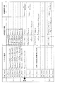
上式により、前回の180℃A区間[i-1] のTDC後のクランク角0℃Aの角速度ω[0,i-1] 、クランク角30℃Aの角速度ω[30,i-1]、クランク角60℃Aの角速度ω[60,i-1]、クランク角90℃Aの角速度ω[90,i-1]、クランク角120℃Aの角速度ω[120,i-1] 、クランク角150℃Aの角速度ω[150,i-1] 、今回の180℃A区間[i] のTDC後のクランク角0℃Aの角速度ω[0,i] を算出する。
From the above equation, the angular velocity ω [0, i-1] at a crank angle of 0 ° A after the TDC of the 180 ° A section [i-1] in the previous time, the angular velocity ω [30, i-1] at a crank angle of 30 ° A , Angular speed ω [60, i-1] with a crank angle of 60 ° C, angular speed ω [90, i-1] with a crank angle of 90 ° C, angular speed ω [120, i-1] with a crank angle of 120 ° C, An angular velocity ω [150, i-1] at an
更に、前回の180℃A区間[i-1] のTDC後のクランク角0℃Aから30℃AまでのロストルクT[0-30,i-1]、クランク角30℃Aから60℃AまでのロストルクT[30-60,i-1] 、クランク角60℃Aから90℃AまでのロストルクT[60-90,i-1] 、クランク角90℃Aから120℃AまでのロストルクT[90-120,i-1]、クランク角120℃Aから150℃AまでのロストルクT[120-150,i-1] 、クランク角150℃Aから今回の180℃A区間[i] のTDC後の0℃AまでのロストルクT[150-0,i-1] を算出する。
Further, loss torque T [0-30, i-1] from crank
T[0-30,i-1]=−J・(ω[30,i-1]2 −ω[0,i-1] 2 )/2
T[30-60,i-1] =−J・(ω[60,i-1]2 −ω[30,i-1]2 )/2
T[60-90,i-1] =−J・(ω[90,i-1]2 −ω[60,i-1]2 )/2
T[90-120,i-1]=−J・(ω[120,i-1] 2 −ω[90,i-1]2 )/2
T[120-150,i-1] =−J・(ω[150,i-1] 2 −ω[120,i-1] 2 )/2
T[150-0,i-1] =−J・(ω[0,i] 2 −ω[150,i-1] 2 )/2
T [0-30, i-1] = − J · (ω [30, i-1] 2 −ω [0, i-1] 2 ) / 2
T [30-60, i-1] = −J ・ (ω [60, i-1] 2 −ω [30, i-1] 2 ) / 2
T [60-90, i-1] = −J · (ω [90, i-1] 2 −ω [60, i-1] 2 ) / 2
T [90-120, i-1] = − J · (ω [120, i-1] 2 −ω [90, i-1] 2 ) / 2
T [120-150, i-1] = − J · (ω [150, i-1] 2 −ω [120, i-1] 2 ) / 2
T [150-0, i-1] = − J · (ω [0, i] 2 −ω [150, i-1] 2 ) / 2
ここで、Jはエンジン21のイナーシャである。これらのロストルクT[0-30,i-1]〜T[150-0,i-1] の算出値は、それぞれレジスタに更新記憶される(図15参照)。
そして、今回の180℃A区間[i] のTDC後の30℃A(現時点)で、角速度ω[30,i]を算出すると共に、ロストルクT[0-30,i]を同様に算出し、このロストルクT[0-30,i]をレジスタに更新記憶する。
Here, J is the inertia of the
Then, at 30 ° C. A (current time) after TDC of the current 180 ° C. section [i], the angular velocity ω [30, i] is calculated, and the loss torque T [0-30, i] is calculated in the same manner. The loss torque T [0-30, i] is updated and stored in the register.
その後、図15に示すように、前回の180℃A区間[i-1] のクランク角30℃Aから60℃AまでのロストルクT[30-60,i-1] を用いて、今回の180℃A区間[i] のTDC後のクランク角60℃Aの予測角速度ω'[60,i] を演算すると共に、クランク角30℃Aから60℃Aに到達するまでの予測到達時間t[30-60,i] を演算し、更に、前回の180℃A区間[i-1] のクランク角60℃Aから90℃AまでのロストルクT[60-90,i-1] と上記予測角速度ω'[60,i] を用いて、今回の180℃A区間[i] のTDC後のクランク角90℃Aの予測角速度ω'[90,i] を演算すると共に、クランク角60℃Aから90℃Aに到達するまでの予測到達時間t[60-90,i] を演算し、更に、前回の180℃A区間[i-1] のクランク角90℃Aから120℃AまでのロストルクT[90-120,i-1]と上記予測角速度ω'[90,i] を用いて、今回の180℃A区間[i] のTDC後のクランク角120℃Aの予測角速度ω'[120,i]を演算すると共に、クランク角90℃Aから120℃Aに到達するまでの予測到達時間t[90-120,i]を演算するという処理を何回も繰り返すことで、エンジン回転降下軌道を予測する(図14参照)。
Then, as shown in FIG. 15, the current 180 ° C. section [i-1] is used for the current 180 ° torque loss T [30-60, i-1] from the
この予測演算は、クランクパルス入力毎(30℃A毎)に次のクランクパルスが入力されるまでの時間を利用して実行され、その都度、エンジン回転降下軌道の予測データが更新される。次のクランクパルスが入力されるまでの演算時間に余裕があれば、エンジン回転が停止するまでのエンジン回転降下軌道を予測するが、演算時間が足りない場合は、予測演算を途中で打ち切って、次のクランク角での実角速度を用いた新たな予測演算に移行する。尚、角速度をエンジン回転速度に換算して予測演算を行うようにしても良いことは言うまでもない。 This prediction calculation is executed using the time until the next crank pulse is input every time the crank pulse is input (every 30 ° C. A), and the prediction data of the engine rotation orbit is updated each time. If the calculation time until the next crank pulse is input has a margin, the engine rotation descent trajectory until the engine rotation stops is predicted, but if the calculation time is insufficient, the prediction calculation is interrupted halfway, The process proceeds to a new prediction calculation using the actual angular velocity at the next crank angle. It goes without saying that the prediction calculation may be performed by converting the angular velocity into the engine rotation speed.
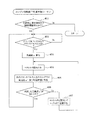
以上説明した本実施例5のエンジン回転降下軌道の予測は、ECU20によって図16のエンジン回転降下軌道予測ルーチンに従って実行される。以下、図16のルーチンの処理内容を説明する。
The prediction of the engine rotation descent trajectory of the fifth embodiment described above is executed by the
図16のエンジン回転降下軌道予測ルーチンは、エンジン運転中(ECU20の電源オン期間中)に所定周期で繰り返し実行され、特許請求の範囲でいう回転降下軌道予測手段としての役割を果たす。本ルーチンが起動されると、まず、ステップ401で、自動停止要求(燃料噴射停止)が発生したか否かを判定し、自動停止要求が発生していなければ、そのまま本ルーチンを終了する。
The engine rotation descent trajectory prediction routine of FIG. 16 is repeatedly executed at a predetermined cycle during engine operation (during the power-on period of the ECU 20), and plays a role as a rotation descent trajectory prediction means in the claims. When this routine is started, first, at
その後、自動停止要求が発生した時点で、ステップ402に進み、クランク角センサからクランクパルスがECU20に入力されたか否かを判定し、クランクパルスが入力されるまで待機する。そして、クランクパルスが入力される毎に、ステップ403に進み、今回のクランクパルス入力時の角速度ωを算出する。
ω=30×2π/(360×tp )
tp :クランクパルス間隔[sec]
Thereafter, when an automatic stop request is generated, the process proceeds to step 402, where it is determined whether or not a crank pulse is input to the
ω = 30 × 2π / (360 × tp)
tp: Crank pulse interval [sec]
この後、ステップ404に進み、レジスタに記憶されたエンジン21のロストルクを読み込む。このロストルクは、150℃A前のクランクパルス入力時に算出してレジスタに記憶したロストルクを用いる。この後、ステップ405に進み、ロストルクを用いて、次のクランクパルスの入力タイミングでの予測角速度ω' を算出すると共に、次のクランクパルスの入力タイミングまでの予測到達時間tを算出する。
Thereafter, the process proceeds to step 404, and the loss torque of the
この後、ステップ406に進み、次のクランクパルスの入力タイミングでの予測角速度ω' が0以下であるか否かで、エンジン回転停止に至るまでのエンジン回転降下軌道を予測し終えたか否かを判定する。このステップ406で、予測角速度ω' が0以下でないと判定されれば、ステップ407に進み、エンジン21のロストルクを算出してレジスタに記憶して、前述したステップ404、405の処理を繰り返して、ロストルクと上記予測角速度ω' を用いて、更にその次のクランクパルスの入力タイミングでの予測角速度ω' と予測到達時間tを算出する処理を繰り返す。
Thereafter, the process proceeds to step 406, where it is determined whether or not the prediction of the engine rotation descent trajectory until the engine rotation stops is made depending on whether or not the predicted angular velocity ω ′ at the input timing of the next crank pulse is 0 or less. judge. If it is determined in
このような30℃A毎の予測角速度ω' と予測到達時間tを何回も繰り返して、予測角速度ω' が0以下になった時点で、エンジン回転停止に至るまでのエンジン回転降下軌道を予測し終えたと判断して、前記ステップ402に戻り、次のクランクパルスが入力されるまで待機する。これにより、クランクパルスが入力される毎に、エンジン回転停止に至るまでのエンジン回転降下軌道の予測演算が行われる。 The predicted angular velocity ω ′ and predicted arrival time t every 30 ° C. are repeated many times, and when the predicted angular velocity ω ′ becomes 0 or less, the engine rotation descent trajectory until the engine rotation is stopped is predicted. When it is determined that the process has been completed, the process returns to step 402 and waits until the next crank pulse is input. Thus, every time a crank pulse is input, a prediction calculation of the engine rotation descent trajectory until the engine rotation is stopped is performed.
尚、次のクランクパルスが入力されるまでの演算時間が、エンジン回転停止に至るまでのエンジン回転降下軌道の予測演算に必要な時間よりも短い場合は、予測演算を途中で打ち切って、次のクランク角での実角速度ωを用いた新たな予測演算に移行する。 If the calculation time until the next crank pulse is input is shorter than the time required for the prediction calculation of the engine rotation descent trajectory until the engine rotation stops, the prediction calculation is interrupted and the next calculation is interrupted. The process proceeds to a new prediction calculation using the actual angular velocity ω at the crank angle.
以上説明した本実施例5によれば、エンジン21を自動停止させる際に、エンジン回転速度が脈動しながら降下する軌道を予測できるため、エンジン回転降下期間中にエンジン回転速度が脈動しても、ピニオン13をリングギヤ23に飛び込ませて噛み合わせる際のピニオン13の駆動タイミング(押し出しタイミング)やモータ12の駆動タイミングを精度良く制御することができる。
According to the fifth embodiment described above, when the
尚、エンジン回転降下軌道を予測する方法は、上記実施例5で説明した方法に限定されず、適宜変更しても良い。
その他、本発明は、エンジン始動制御システムの構成を適宜変更しても良い等、要旨を逸脱しない範囲で種々変更して実施できる。
The method for predicting the engine rotation descending trajectory is not limited to the method described in the fifth embodiment, and may be changed as appropriate.
In addition, the present invention can be implemented with various changes without departing from the gist, such as the configuration of the engine start control system may be changed as appropriate.
11…スタータ、12…モータ、13…ピニオン、14…電磁アクチュエータ、18…バッテリ、19…リレー、20…ECU(第1〜第4の再始動制御手段,待機再始動制御手段,回転降下軌道予測手段,制御手段)、21…エンジン、22…クランク軸、23…リングギヤ、24…スイッチング素子、25…リレー
DESCRIPTION OF
Claims (18)
前記エンジンの自動停止によりエンジン回転速度が降下するエンジン回転降下期間中に前記エンジン回転速度が第1の回転速度よりも高い第1の回転速度領域で前記エンジン再始動要求が発生したときに、前記スタータによるクランキングを行わずに燃料噴射を再開して前記エンジンを再始動させる第1の再始動制御手段と、
前記エンジン回転降下期間中に前記エンジン回転速度が前記第1の回転速度以下で第2の回転速度よりも高い第2の回転速度領域で前記エンジン再始動要求が発生したときに、前記モータにより前記ピニオンの回転速度を同期させた後に前記アクチュエータにより前記ピニオンを前記リングギヤに噛み合わせて前記スタータによるクランキングを開始して前記エンジンを再始動させる第2の再始動制御手段と、
前記エンジン回転降下期間中に前記エンジン回転速度が前記第2の回転速度以下で且つ50〜450rpmの範囲内に設定された第3の回転速度よりも高い待機回転速度領域で前記エンジン再始動要求が発生したときに、前記スタータによるクランキングを行わずに、その後、前記エンジン回転速度が前記第3の回転速度以下の第3の回転速度領域になったときに、前記アクチュエータにより前記ピニオンを前記リングギヤに噛み合わせた後又はその噛み合わせの途中に前記モータにより前記ピニオンを回転させて前記スタータによるクランキングを開始して前記エンジンを再始動させる待機再始動制御手段と、
前記エンジン回転降下期間中に前記エンジン回転速度が前記第3の回転速度以下の第3の回転速度領域で前記エンジン再始動要求が発生したときに、前記アクチュエータにより前記ピニオンを前記リングギヤに噛み合わせた後又はその噛み合わせの途中に前記モータにより前記ピニオンを回転させて前記スタータによるクランキングを開始して前記エンジンを再始動させる第3の再始動制御手段と
を備えていることを特徴とするエンジン自動停止始動制御装置。 A starter that can individually operate a motor that rotationally drives the pinion and an actuator that meshes the pinion with a ring gear that is connected to the crankshaft of the engine, and automatically stops the engine when an engine automatic stop request occurs, In the engine automatic stop / start control device for restarting the engine when an engine restart request is generated,
When the engine restart request is generated in a first rotation speed region in which the engine rotation speed is higher than the first rotation speed during an engine rotation decrease period in which the engine rotation speed decreases due to the automatic stop of the engine, First restart control means for restarting fuel injection and restarting the engine without cranking by a starter;
When the engine restart request is generated in a second rotation speed region in which the engine rotation speed is equal to or lower than the first rotation speed and higher than the second rotation speed during the engine rotation drop period, Second restart control means for causing the starter to start cranking by restarting the engine by meshing the pinion with the ring gear by the actuator after synchronizing the rotation speed of the pinion;
The engine restart request is made in a standby rotational speed region in which the engine rotational speed is equal to or lower than the second rotational speed and higher than a third rotational speed set in a range of 50 to 450 rpm during the engine rotational drop period. When it occurs, the crank is not cranked by the starter, and when the engine rotation speed is in a third rotation speed region equal to or lower than the third rotation speed, the pinion is moved by the actuator to the ring gear. Standby restart control means for starting the cranking by the starter by restarting the engine by rotating the pinion by the motor during or after the meshing,
When the engine restart request is generated in the third rotation speed region where the engine rotation speed is equal to or lower than the third rotation speed during the engine rotation descent period, the pinion is engaged with the ring gear by the actuator. And a third restart control means for restarting the engine by starting the cranking by the starter by rotating the pinion by the motor after or in the middle of the engagement. Automatic stop / start control device.
前記エンジンの自動停止によりエンジン回転速度が降下するエンジン回転降下期間中に前記エンジン回転速度が第1の回転速度以下で第2の回転速度よりも高い第2の回転速度領域で前記エンジン再始動要求が発生したときに、前記モータにより前記ピニオンの回転速度を前記リングギヤの回転速度に同期させた後に前記アクチュエータにより前記ピニオンを前記リングギヤに噛み合わせて前記スタータによるクランキングを開始して前記エンジンを再始動させる第2の再始動制御手段と、
前記エンジン回転降下期間中に前記エンジン回転速度が前記第2の回転速度以下で且つ50〜450rpmの範囲内に設定された第3の回転速度よりも高い待機回転速度領域で前記エンジン再始動要求が発生したときに、前記スタータによるクランキングを行わずに、その後、前記エンジン回転速度が前記第3の回転速度以下の第3の回転速度領域になったときに、前記アクチュエータにより前記ピニオンを前記リングギヤに噛み合わせた後又はその噛み合わせの途中に前記モータにより前記ピニオンを回転させて前記スタータによるクランキングを開始して前記エンジンを再始動させる待機再始動制御手段と、
前記エンジン回転降下期間中に前記エンジン回転速度が前記第3の回転速度以下の第3の回転速度領域で前記エンジン再始動要求が発生したときに、前記アクチュエータにより前記ピニオンを前記リングギヤに噛み合わせた後又はその噛み合わせの途中に前記モータにより前記ピニオンを回転させて前記スタータによるクランキングを開始して前記エンジンを再始動させる第3の再始動制御手段と
を備えていることを特徴とするエンジン自動停止始動制御装置。 A starter that can individually operate a motor that rotationally drives the pinion and an actuator that meshes the pinion with a ring gear that is connected to the crankshaft of the engine, and automatically stops the engine when an engine automatic stop request occurs, In the engine automatic stop / start control device for restarting the engine when an engine restart request is generated,
The engine restart request in a second rotational speed region in which the engine rotational speed is equal to or lower than the first rotational speed and higher than the second rotational speed during an engine rotational speed drop period in which the engine rotational speed decreases due to the automatic engine stop. When the rotation of the pinion is synchronized with the rotation speed of the ring gear by the motor, the pinion is engaged with the ring gear by the actuator, cranking by the starter is started, and the engine is restarted. Second restart control means for starting;
The engine restart request is made in a standby rotational speed region in which the engine rotational speed is equal to or lower than the second rotational speed and higher than a third rotational speed set in a range of 50 to 450 rpm during the engine rotational drop period. When it occurs, the crank is not cranked by the starter, and when the engine rotation speed is in a third rotation speed region equal to or lower than the third rotation speed, the pinion is moved by the actuator to the ring gear. Standby restart control means for starting the cranking by the starter by restarting the engine by rotating the pinion by the motor during or after the meshing,
When the engine restart request is generated in the third rotation speed region where the engine rotation speed is equal to or lower than the third rotation speed during the engine rotation descent period, the pinion is engaged with the ring gear by the actuator. And a third restart control means for restarting the engine by starting the cranking by the starter by rotating the pinion by the motor after or in the middle of the engagement. Automatic stop / start control device.
前記第2の再始動制御手段は、前記リングギヤの回転速度が前記ピニオンの回転速度よりも高く且つ前記リングギヤの回転速度と前記ピニオンの回転速度との回転速度差が所定値以下になったときに前記ピニオンの回転速度が前記リングギヤの回転速度に同期したと判断する手段を有することを特徴とする請求項1又は2に記載のエンジン自動停止始動制御装置。 The starter is provided with a one-way clutch that does not transmit power from the pinion to the motor in the engine rotation direction,
When the rotational speed of the ring gear is higher than the rotational speed of the pinion and the rotational speed difference between the rotational speed of the ring gear and the rotational speed of the pinion becomes a predetermined value or less, the second restart control means The engine automatic stop / start control device according to claim 1 or 2, further comprising means for determining that the rotation speed of the pinion is synchronized with the rotation speed of the ring gear.
前記第2の再始動制御手段は、前記リングギヤのピッチ円上の周速度が前記ピニオンのピッチ円上の周速度よりも高く且つ前記リングギヤのピッチ円上の周速度と前記ピニオンのピッチ円上の周速度との周速度差が3.1m/秒の範囲内になったときに前記ピニオンの回転速度が前記リングギヤの回転速度に同期したと判断する手段を有することを特徴とする請求項1又は2に記載のエンジン自動停止始動制御装置。 The starter is provided with a one-way clutch that does not transmit power from the pinion to the motor in the engine rotation direction,
The second restart control means is configured such that the peripheral speed on the pitch circle of the ring gear is higher than the peripheral speed on the pitch circle of the pinion, and the peripheral speed on the pitch circle of the ring gear and the pitch circle of the pinion 2. A means for determining that the rotational speed of the pinion is synchronized with the rotational speed of the ring gear when the peripheral speed difference from the peripheral speed is within a range of 3.1 m / sec. 2. The engine automatic stop / start control device according to 2.
前記エンジンの自動停止によりエンジン回転速度が降下するエンジン回転降下期間中に前記エンジン回転速度が第1の回転速度よりも高い第1の回転速度領域で前記エンジン再始動要求が発生したときに、前記スタータによるクランキングを行わずに燃料噴射を再開して前記エンジンを再始動させる第1の再始動制御手段と、
前記エンジン回転降下期間中に前記エンジン回転速度が前記第1の回転速度以下で第2の回転速度よりも高い待機回転速度領域で前記エンジン再始動要求が発生したときに、前記スタータによるクランキングを行わずに、その後、前記エンジン回転速度が前記第2の回転速度以下で且つ50〜450rpmの範囲内に設定された第3の回転速度よりも高い第2の回転速度領域になったときに、前記モータにより前記ピニオンの回転速度を前記リングギヤの回転速度に同期させた後に前記アクチュエータにより前記ピニオンを前記リングギヤに噛み合わせて前記スタータによるクランキングを開始して前記エンジンを再始動させる待機再始動制御手段と
を備えていることを特徴とするエンジン自動停止始動制御装置。 A starter that can individually operate a motor that rotationally drives the pinion and an actuator that meshes the pinion with a ring gear that is connected to the crankshaft of the engine, and automatically stops the engine when an engine automatic stop request occurs, In the engine automatic stop / start control device for restarting the engine when an engine restart request is generated,
When the engine restart request is generated in a first rotation speed region in which the engine rotation speed is higher than the first rotation speed during an engine rotation decrease period in which the engine rotation speed decreases due to the automatic stop of the engine, First restart control means for restarting fuel injection and restarting the engine without cranking by a starter;
When the engine restart request is generated in the standby rotational speed region where the engine rotational speed is equal to or lower than the first rotational speed and higher than the second rotational speed during the engine rotational descent period, cranking by the starter is performed. Without performing , after that, when the engine rotation speed becomes a second rotation speed region that is lower than the second rotation speed and higher than the third rotation speed set in the range of 50 to 450 rpm , Standby restart control in which the rotation speed of the pinion is synchronized with the rotation speed of the ring gear by the motor, and then the crank is started by the starter by engaging the pinion with the ring gear by the actuator and restarting the engine. And an engine automatic stop / start control device.
前記エンジンの自動停止によりエンジン回転速度が降下するエンジン回転降下期間中に前記エンジン回転速度が第1の回転速度よりも高い第1の回転速度領域で前記エンジン再始動要求が発生したときに、前記スタータによるクランキングを行わずに燃料噴射を再開して前記エンジンを再始動させる第1の再始動制御手段と、
前記エンジン回転降下期間中に前記エンジン回転速度が前記第1の回転速度以下で且つ50〜450rpmの範囲内に設定された第3の回転速度よりも高い待機回転速度領域で前記エンジン再始動要求が発生したときに、前記スタータによるクランキングを行わずに、その後、前記エンジン回転速度が前記第3の回転速度以下の第3の回転速度領域になったときに、前記アクチュエータにより前記ピニオンを前記リングギヤに噛み合わせた後又はその噛み合わせの途中に前記モータにより前記ピニオンを回転させて前記スタータによるクランキングを開始して前記エンジンを再始動させる待機再始動制御手段と
を備えていることを特徴とするエンジン自動停止始動制御装置。 A starter that can individually operate a motor that rotationally drives the pinion and an actuator that meshes the pinion with a ring gear that is connected to the crankshaft of the engine, and automatically stops the engine when an engine automatic stop request occurs, In the engine automatic stop / start control device for restarting the engine when an engine restart request is generated,
When the engine restart request is generated in a first rotation speed region in which the engine rotation speed is higher than the first rotation speed during an engine rotation decrease period in which the engine rotation speed decreases due to the automatic stop of the engine, First restart control means for restarting fuel injection and restarting the engine without cranking by a starter;
The engine restart request is made in a standby rotational speed region in which the engine rotational speed is equal to or lower than the first rotational speed and higher than a third rotational speed set in a range of 50 to 450 rpm during the engine rotational drop period. When it occurs, the crank is not cranked by the starter, and when the engine rotation speed is in a third rotation speed region equal to or lower than the third rotation speed, the pinion is moved by the actuator to the ring gear. Standby restart control means for starting the cranking by the starter and restarting the engine by rotating the pinion by the motor after or during the engagement. An engine automatic stop / start control device.
前記回転降下軌道予測手段によるエンジン回転降下軌道の予測データに基づいて前記待機回転速度領域を判定すると共に前記ピニオンの駆動タイミングと前記モータの駆動タイミングを決定する制御手段と
を備えていることを特徴とする請求項1乃至17のいずれかに記載のエンジン自動停止始動制御装置。 Rotational descent trajectory predicting means for predicting a trajectory in which the engine rotational speed decreases due to the automatic stop of the engine (hereinafter referred to as “engine rotational descent trajectory”);
Control means for determining the standby rotational speed region based on the prediction data of the engine rotation descent trajectory by the rotation descent trajectory prediction means and determining the drive timing of the pinion and the drive timing of the motor. An engine automatic stop / start control device according to any one of claims 1 to 17 .
Priority Applications (4)
| Application Number | Priority Date | Filing Date | Title |
|---|---|---|---|
| JP2010265000A JP5656013B2 (en) | 2010-01-11 | 2010-11-29 | Engine automatic stop / start control device |
| US12/978,856 US8793061B2 (en) | 2010-01-11 | 2010-12-27 | Control device for controlling automatic engine stop and start |
| DE102011000006A DE102011000006A1 (en) | 2010-01-11 | 2011-01-03 | Control device for controlling automatic machine stop and start |
| CN201110041777.9A CN102135027B (en) | 2010-01-11 | 2011-01-11 | Control device for controlling automatic engine stop and start |
Applications Claiming Priority (3)
| Application Number | Priority Date | Filing Date | Title |
|---|---|---|---|
| JP2010003512 | 2010-01-11 | ||
| JP2010003512 | 2010-01-11 | ||
| JP2010265000A JP5656013B2 (en) | 2010-01-11 | 2010-11-29 | Engine automatic stop / start control device |
Publications (2)
| Publication Number | Publication Date |
|---|---|
| JP2011157958A JP2011157958A (en) | 2011-08-18 |
| JP5656013B2 true JP5656013B2 (en) | 2015-01-21 |
Family
ID=44259183
Family Applications (1)
| Application Number | Title | Priority Date | Filing Date |
|---|---|---|---|
| JP2010265000A Active JP5656013B2 (en) | 2010-01-11 | 2010-11-29 | Engine automatic stop / start control device |
Country Status (4)
| Country | Link |
|---|---|
| US (1) | US8793061B2 (en) |
| JP (1) | JP5656013B2 (en) |
| CN (1) | CN102135027B (en) |
| DE (1) | DE102011000006A1 (en) |
Families Citing this family (38)
| Publication number | Priority date | Publication date | Assignee | Title |
|---|---|---|---|---|
| DE102008040945B4 (en) * | 2008-08-01 | 2019-08-14 | Seg Automotive Germany Gmbh | Method for engaging a starting pinion of a starting device in a ring gear of an internal combustion engine |
| JP4835774B2 (en) * | 2009-09-04 | 2011-12-14 | 株式会社デンソー | Engine stop / start control device |
| US8251034B2 (en) * | 2009-12-15 | 2012-08-28 | GM Global Technology Operations LLC | Control of a pre-spun starter |
| DE102010040562B4 (en) * | 2010-09-10 | 2022-02-03 | Robert Bosch Gmbh | Method for restarting an internal combustion engine |
| US8666574B2 (en) * | 2011-04-21 | 2014-03-04 | Deere & Company | In-vehicle estimation of electric traction motor performance |
| DE102011088106B4 (en) * | 2011-12-09 | 2021-07-01 | Robert Bosch Gmbh | Quick restart at engine stop with conventional starters |
| DE102011090149A1 (en) * | 2011-12-30 | 2013-07-04 | Robert Bosch Gmbh | Method for controlling an organ in the air supply tract of an internal combustion engine, in particular a throttle valve |
| US8829845B2 (en) * | 2012-02-28 | 2014-09-09 | Remy Technologies, Llc | Starter machine system and method |
| JP5777542B2 (en) * | 2012-02-29 | 2015-09-09 | 日立オートモティブシステムズ株式会社 | Idle stop control device for internal combustion engine |
| US8965616B2 (en) | 2012-05-04 | 2015-02-24 | Ford Global Technologies, Llc | Methods and systems for reducing gear lash noise |
| US8977449B2 (en) | 2012-05-04 | 2015-03-10 | Ford Global Technologies, Llc | Methods and systems for holding a vehicle stopped on a hill |
| US8938327B2 (en) | 2012-05-04 | 2015-01-20 | Ford Global Technologies, Llc | Methods and systems for transitioning between driveline braking modes |
| US9039570B2 (en) | 2012-05-04 | 2015-05-26 | Ford Global Technologies, Llc | Methods and systems for adjusting driveline disconnect clutch operation |
| US9108632B2 (en) | 2012-05-04 | 2015-08-18 | Ford Global Technologies, Llc | Methods and systems for operating a driveline clutch |
| US9108614B2 (en) | 2012-05-04 | 2015-08-18 | Ford Global Technologies, Llc | Methods and systems for adapting a driveline disconnect clutch transfer function |
| US9656665B2 (en) | 2012-05-04 | 2017-05-23 | Ford Global Technologies, Llc | Methods and systems for a driveline dual mass flywheel |
| US9068546B2 (en) | 2012-05-04 | 2015-06-30 | Ford Global Technologies, Llc | Methods and systems for engine cranking |
| US8813881B2 (en) | 2012-05-04 | 2014-08-26 | Ford Global Technologies, Llc | Methods and systems for a vehicle driveline power take off |
| US8998771B2 (en) | 2012-05-04 | 2015-04-07 | Ford Global Technologies, Llc | Methods and systems for a vehicle driveline |
| US9322380B2 (en) | 2012-05-04 | 2016-04-26 | Ford Global Technologies, Llc | Methods and systems for engine starting during a shift |
| US9156469B2 (en) | 2012-05-04 | 2015-10-13 | Ford Global Technologies, Llc | Methods and systems for a driveline disconnect clutch |
| US9650036B2 (en) | 2012-05-04 | 2017-05-16 | Ford Global Technologies, Llc | Methods and systems for adjusting cylinder air charge |
| US8808140B2 (en) | 2012-05-04 | 2014-08-19 | Ford Global Technologies, Llc | Methods and systems for driveline sailing mode entry |
| US9447747B2 (en) * | 2012-05-04 | 2016-09-20 | Ford Global Technologies, Llc | Methods and systems for stopping an engine |
| US8932179B2 (en) | 2012-05-04 | 2015-01-13 | Ford Global Technologies, Llc | Methods and systems for transitioning between braking modes |
| US9115682B2 (en) | 2012-05-04 | 2015-08-25 | Ford Global Technologies, Llc | Methods and systems for operating a driveline disconnect clutch |
| US11084485B2 (en) | 2012-07-24 | 2021-08-10 | Magna Steyr Fahrzeugtechnik Ag & Co Kg | Method for operating a hybrid vehicle |
| EP2689981B1 (en) * | 2012-07-24 | 2017-09-20 | MAGNA STEYR Engineering AG & Co KG | Operating strategy for the power management of an electric vehicle for the VKM start request of a range extender |
| JP5644843B2 (en) * | 2012-11-21 | 2014-12-24 | トヨタ自動車株式会社 | Vehicle control device |
| JP5910476B2 (en) * | 2012-12-06 | 2016-04-27 | 株式会社デンソー | Engine starter |
| JP5945068B2 (en) * | 2013-04-01 | 2016-07-05 | 本田技研工業株式会社 | Power transmission device for vehicle |
| WO2014184889A1 (en) * | 2013-05-15 | 2014-11-20 | 三菱電機株式会社 | Automatic stopping/restarting device for internal combustion engine |
| US9393950B2 (en) * | 2013-07-22 | 2016-07-19 | Ford Global Technologies, Llc | Methods and systems for restarting an engine |
| US9227630B2 (en) * | 2014-02-17 | 2016-01-05 | Ford Global Technologies, Llc | Smoothing hybrid vehicle engine shutdown |
| JP6547676B2 (en) * | 2016-05-12 | 2019-07-24 | 株式会社デンソー | Engine start control system |
| US10480476B2 (en) * | 2018-04-24 | 2019-11-19 | GM Global Technology Operations LLC | Starter system and method of control |
| US10677212B2 (en) * | 2018-05-01 | 2020-06-09 | GM Global Technology Operations LLC | Method and apparatus for controlled stopping of internal combustion engine |
| JP7156830B2 (en) * | 2018-06-14 | 2022-10-19 | 株式会社Subaru | vehicle controller |
Family Cites Families (23)
| Publication number | Priority date | Publication date | Assignee | Title |
|---|---|---|---|---|
| JP4321796B2 (en) * | 2000-08-10 | 2009-08-26 | 株式会社デンソー | Starter control method |
| JP4211208B2 (en) * | 2000-08-23 | 2009-01-21 | トヨタ自動車株式会社 | Fuel consumption saving car |
| US7134414B2 (en) | 2003-02-10 | 2006-11-14 | Robert Bosch Gmbh | Method and device for starting an internal combustion engine |
| JP3945442B2 (en) * | 2003-03-31 | 2007-07-18 | マツダ株式会社 | Engine starter |
| JP4214401B2 (en) * | 2004-05-18 | 2009-01-28 | 株式会社デンソー | Engine automatic stop / restart device |
| JP2006029247A (en) * | 2004-07-20 | 2006-02-02 | Denso Corp | Stop and start control device for engine |
| JP4415841B2 (en) * | 2004-12-07 | 2010-02-17 | マツダ株式会社 | 4-cycle engine starter |
| JP4453536B2 (en) * | 2004-12-10 | 2010-04-21 | トヨタ自動車株式会社 | Drive device, automobile equipped with the drive device, and control method of drive device |
| JP4466443B2 (en) * | 2005-03-31 | 2010-05-26 | マツダ株式会社 | Vehicle engine starting device |
| DE102006011644A1 (en) * | 2006-03-06 | 2007-09-13 | Robert Bosch Gmbh | Device having a first gear part for meshing in a second gear part, in particular starting device with a pinion for meshing in a ring gear of an internal combustion engine and method for operating such a device |
| JP2008121648A (en) * | 2006-11-16 | 2008-05-29 | Hitachi Ltd | Control device for internal combustion engine |
| JP2009036115A (en) * | 2007-08-02 | 2009-02-19 | Mazda Motor Corp | Vehicle engine controller |
| JP2009221926A (en) * | 2008-03-14 | 2009-10-01 | Toyota Motor Corp | Start control system of internal combustion engine |
| JP5139167B2 (en) | 2008-06-19 | 2013-02-06 | トヨタ自動車株式会社 | Battery pack recycling method and battery pack recycling apparatus |
| JP5007839B2 (en) | 2008-09-02 | 2012-08-22 | 株式会社デンソー | Engine automatic stop / start control device |
| JP4737571B2 (en) * | 2008-09-08 | 2011-08-03 | 株式会社デンソー | Engine starter |
| EP3144520B1 (en) * | 2009-01-21 | 2021-03-31 | Denso Corporation | System for restarting internal combustion engine when engine restart condition is met |
| DE102010061084A1 (en) * | 2009-12-08 | 2011-07-21 | DENSO CORPORATION, Aichi-pref. | System for cranking an internal combustion engine by engaging a pinion with a ring gear |
| JP5094889B2 (en) * | 2010-01-14 | 2012-12-12 | 日立オートモティブシステムズ株式会社 | Fuel consumption-saving vehicle control system |
| US8510019B2 (en) * | 2010-01-20 | 2013-08-13 | Denso Corporation | Control device of automatic engine stop and start |
| JP5025752B2 (en) * | 2010-03-30 | 2012-09-12 | 三菱電機株式会社 | Automatic stop / restart device for internal combustion engine |
| JP5464095B2 (en) * | 2010-08-02 | 2014-04-09 | 株式会社デンソー | Engine stop / start control device |
| JP5236044B2 (en) * | 2011-05-11 | 2013-07-17 | 三菱電機株式会社 | Automatic stop / restart device for internal combustion engine |
-
2010
- 2010-11-29 JP JP2010265000A patent/JP5656013B2/en active Active
- 2010-12-27 US US12/978,856 patent/US8793061B2/en active Active
-
2011
- 2011-01-03 DE DE102011000006A patent/DE102011000006A1/en not_active Withdrawn
- 2011-01-11 CN CN201110041777.9A patent/CN102135027B/en not_active Expired - Fee Related
Also Published As
| Publication number | Publication date |
|---|---|
| CN102135027B (en) | 2014-04-30 |
| US20110172901A1 (en) | 2011-07-14 |
| US8793061B2 (en) | 2014-07-29 |
| DE102011000006A1 (en) | 2011-09-01 |
| JP2011157958A (en) | 2011-08-18 |
| CN102135027A (en) | 2011-07-27 |
Similar Documents
| Publication | Publication Date | Title |
|---|---|---|
| JP5656013B2 (en) | Engine automatic stop / start control device | |
| JP5007839B2 (en) | Engine automatic stop / start control device | |
| JP4835774B2 (en) | Engine stop / start control device | |
| JP5392280B2 (en) | Engine automatic stop / start control device | |
| JP5464095B2 (en) | Engine stop / start control device | |
| JP5447298B2 (en) | Engine automatic stop / start control device | |
| JP5321524B2 (en) | Engine automatic stop / start control device | |
| JP2011169248A (en) | Control device of starter | |
| CN102597490B (en) | Engine starting device | |
| JP5428765B2 (en) | Automatic stop / start control device for internal combustion engine | |
| JP4735737B2 (en) | Engine stop / start control device | |
| JP5007765B2 (en) | Engine automatic stop / start control device | |
| JP5353721B2 (en) | Engine stop / start control device | |
| JP6076485B2 (en) | Engine automatic stop / restart device | |
| JP2011190799A (en) | Engine stop/start control device | |
| JP2012102620A (en) | Vehicle control device | |
| JP5370173B2 (en) | Engine automatic stop / start control device | |
| JP5561128B2 (en) | Engine automatic stop / start control device | |
| JP2013047466A (en) | Engine automatic restart device of idling stop vehicle | |
| JP5240262B2 (en) | Engine automatic stop / start control device | |
| JP5724238B2 (en) | Engine stop / start control device | |
| JP2015055217A (en) | Idling stop control device |
Legal Events
| Date | Code | Title | Description |
|---|---|---|---|
| A621 | Written request for application examination |
Free format text: JAPANESE INTERMEDIATE CODE: A621 Effective date: 20130121 |
|
| A977 | Report on retrieval |
Free format text: JAPANESE INTERMEDIATE CODE: A971007 Effective date: 20131029 |
|
| A131 | Notification of reasons for refusal |
Free format text: JAPANESE INTERMEDIATE CODE: A131 Effective date: 20131107 |
|
| A131 | Notification of reasons for refusal |
Free format text: JAPANESE INTERMEDIATE CODE: A131 Effective date: 20140213 |
|
| A521 | Request for written amendment filed |
Free format text: JAPANESE INTERMEDIATE CODE: A523 Effective date: 20140411 |
|
| A02 | Decision of refusal |
Free format text: JAPANESE INTERMEDIATE CODE: A02 Effective date: 20140704 |
|
| A521 | Request for written amendment filed |
Free format text: JAPANESE INTERMEDIATE CODE: A523 Effective date: 20141003 |
|
| A911 | Transfer to examiner for re-examination before appeal (zenchi) |
Free format text: JAPANESE INTERMEDIATE CODE: A911 Effective date: 20141010 |
|
| TRDD | Decision of grant or rejection written | ||
| A01 | Written decision to grant a patent or to grant a registration (utility model) |
Free format text: JAPANESE INTERMEDIATE CODE: A01 Effective date: 20141029 |
|
| A61 | First payment of annual fees (during grant procedure) |
Free format text: JAPANESE INTERMEDIATE CODE: A61 Effective date: 20141111 |
|
| R151 | Written notification of patent or utility model registration |
Ref document number: 5656013 Country of ref document: JP Free format text: JAPANESE INTERMEDIATE CODE: R151 |
|
| R250 | Receipt of annual fees |
Free format text: JAPANESE INTERMEDIATE CODE: R250 |
|
| R250 | Receipt of annual fees |
Free format text: JAPANESE INTERMEDIATE CODE: R250 |
|
| R250 | Receipt of annual fees |
Free format text: JAPANESE INTERMEDIATE CODE: R250 |
|
| R250 | Receipt of annual fees |
Free format text: JAPANESE INTERMEDIATE CODE: R250 |
|
| R250 | Receipt of annual fees |
Free format text: JAPANESE INTERMEDIATE CODE: R250 |
|
| R250 | Receipt of annual fees |
Free format text: JAPANESE INTERMEDIATE CODE: R250 |
|
| R250 | Receipt of annual fees |
Free format text: JAPANESE INTERMEDIATE CODE: R250 |
|
| R250 | Receipt of annual fees |
Free format text: JAPANESE INTERMEDIATE CODE: R250 |