JP5653885B2 - Solar furnace equipment - Google Patents
Solar furnace equipment Download PDFInfo
- Publication number
- JP5653885B2 JP5653885B2 JP2011232669A JP2011232669A JP5653885B2 JP 5653885 B2 JP5653885 B2 JP 5653885B2 JP 2011232669 A JP2011232669 A JP 2011232669A JP 2011232669 A JP2011232669 A JP 2011232669A JP 5653885 B2 JP5653885 B2 JP 5653885B2
- Authority
- JP
- Japan
- Prior art keywords
- light receiving
- light
- heat medium
- heat
- solar furnace
- Prior art date
- Legal status (The legal status is an assumption and is not a legal conclusion. Google has not performed a legal analysis and makes no representation as to the accuracy of the status listed.)
- Active
Links
- 239000000126 substance Substances 0.000 claims description 6
- XLYOFNOQVPJJNP-UHFFFAOYSA-N water Substances O XLYOFNOQVPJJNP-UHFFFAOYSA-N 0.000 description 27
- 238000009434 installation Methods 0.000 description 13
- 238000011084 recovery Methods 0.000 description 9
- 238000012546 transfer Methods 0.000 description 7
- 230000003287 optical effect Effects 0.000 description 4
- 230000000903 blocking effect Effects 0.000 description 3
- 238000009792 diffusion process Methods 0.000 description 3
- 238000010438 heat treatment Methods 0.000 description 3
- 238000004519 manufacturing process Methods 0.000 description 3
- 239000002184 metal Substances 0.000 description 3
- 238000006243 chemical reaction Methods 0.000 description 2
- 239000012530 fluid Substances 0.000 description 2
- 239000011810 insulating material Substances 0.000 description 2
- 238000009413 insulation Methods 0.000 description 2
- 239000007788 liquid Substances 0.000 description 2
- 238000012423 maintenance Methods 0.000 description 2
- 238000010248 power generation Methods 0.000 description 2
- 238000007792 addition Methods 0.000 description 1
- 238000012217 deletion Methods 0.000 description 1
- 230000037430 deletion Effects 0.000 description 1
- 238000010586 diagram Methods 0.000 description 1
- 239000000463 material Substances 0.000 description 1
- 238000000034 method Methods 0.000 description 1
- 238000012986 modification Methods 0.000 description 1
- 230000004048 modification Effects 0.000 description 1
- 230000005855 radiation Effects 0.000 description 1
Images


Classifications
-
- F—MECHANICAL ENGINEERING; LIGHTING; HEATING; WEAPONS; BLASTING
- F24—HEATING; RANGES; VENTILATING
- F24S—SOLAR HEAT COLLECTORS; SOLAR HEAT SYSTEMS
- F24S23/00—Arrangements for concentrating solar-rays for solar heat collectors
- F24S23/70—Arrangements for concentrating solar-rays for solar heat collectors with reflectors
- F24S23/77—Arrangements for concentrating solar-rays for solar heat collectors with reflectors with flat reflective plates
-
- F—MECHANICAL ENGINEERING; LIGHTING; HEATING; WEAPONS; BLASTING
- F24—HEATING; RANGES; VENTILATING
- F24S—SOLAR HEAT COLLECTORS; SOLAR HEAT SYSTEMS
- F24S20/00—Solar heat collectors specially adapted for particular uses or environments
- F24S20/20—Solar heat collectors for receiving concentrated solar energy, e.g. receivers for solar power plants
-
- F—MECHANICAL ENGINEERING; LIGHTING; HEATING; WEAPONS; BLASTING
- F24—HEATING; RANGES; VENTILATING
- F24S—SOLAR HEAT COLLECTORS; SOLAR HEAT SYSTEMS
- F24S23/00—Arrangements for concentrating solar-rays for solar heat collectors
- F24S23/30—Arrangements for concentrating solar-rays for solar heat collectors with lenses
-
- F—MECHANICAL ENGINEERING; LIGHTING; HEATING; WEAPONS; BLASTING
- F24—HEATING; RANGES; VENTILATING
- F24S—SOLAR HEAT COLLECTORS; SOLAR HEAT SYSTEMS
- F24S80/00—Details, accessories or component parts of solar heat collectors not provided for in groups F24S10/00-F24S70/00
- F24S80/50—Elements for transmitting incoming solar rays and preventing outgoing heat radiation; Transparent coverings
- F24S80/54—Elements for transmitting incoming solar rays and preventing outgoing heat radiation; Transparent coverings using evacuated elements
-
- Y—GENERAL TAGGING OF NEW TECHNOLOGICAL DEVELOPMENTS; GENERAL TAGGING OF CROSS-SECTIONAL TECHNOLOGIES SPANNING OVER SEVERAL SECTIONS OF THE IPC; TECHNICAL SUBJECTS COVERED BY FORMER USPC CROSS-REFERENCE ART COLLECTIONS [XRACs] AND DIGESTS
- Y02—TECHNOLOGIES OR APPLICATIONS FOR MITIGATION OR ADAPTATION AGAINST CLIMATE CHANGE
- Y02E—REDUCTION OF GREENHOUSE GAS [GHG] EMISSIONS, RELATED TO ENERGY GENERATION, TRANSMISSION OR DISTRIBUTION
- Y02E10/00—Energy generation through renewable energy sources
- Y02E10/40—Solar thermal energy, e.g. solar towers
Landscapes
- Engineering & Computer Science (AREA)
- Physics & Mathematics (AREA)
- Life Sciences & Earth Sciences (AREA)
- Sustainable Development (AREA)
- Sustainable Energy (AREA)
- Thermal Sciences (AREA)
- Chemical & Material Sciences (AREA)
- Combustion & Propulsion (AREA)
- Mechanical Engineering (AREA)
- General Engineering & Computer Science (AREA)
- Photovoltaic Devices (AREA)
- Optical Elements Other Than Lenses (AREA)
Description
本発明は、太陽炉装置に関する。詳しくは、太陽光線を受光して熱エネルギーを取り出すための受光部を備えた太陽炉装置に関する。 The present invention relates to a solar furnace apparatus. In detail, it is related with the solar furnace apparatus provided with the light-receiving part for light-receiving sunlight and taking out thermal energy.
従来、太陽光線を集光してその熱エネルギーを利用することが広く行われている。この際、集光された太陽光線を受光する受光部に熱媒体を流通させて熱エネルギーを取り出すことが一般的に行われている。
例えば、特許文献1には、太陽光線をヘリオスタットで集光してケーシングとなる受熱器本体の開口部に導き、この受熱器本体の内壁面に沿って配設された熱交換受熱管に圧縮空気を流通させて加熱し、加熱された圧縮空気を用いてガスタービンユニットにより発電を行う技術が開示されている。ここで、受熱器本体の内壁面には全域にわたって断熱材が取り付けられて、受熱器本体から失われる圧縮空気の熱エネルギーを低減させるようになっている。
2. Description of the Related Art Conventionally, it is widely performed to collect sunlight rays and use the thermal energy. At this time, generally, a heat medium is circulated through a light receiving unit that receives the collected sunlight to extract heat energy.
For example, in Patent Document 1, sunlight is condensed by a heliostat, led to an opening of a heat receiver body serving as a casing, and compressed into a heat exchange heat receiving pipe disposed along the inner wall surface of the heat receiver body. A technique is disclosed in which air is circulated and heated, and power is generated by a gas turbine unit using the heated compressed air. Here, a heat insulating material is attached to the inner wall surface of the heat receiver main body over the entire area so as to reduce the thermal energy of the compressed air lost from the heat receiver main body.
しかし、上記従来技術では、受熱器本体からその開口部を通して熱エネルギーが失われることを防ぐことができないという問題があった。
本発明は、上記した問題を解決するものとして創案されたものである。すなわち、本発明が解決しようとする課題は、太陽光線を受光部に受光させる窓部分から失われる熱エネルギーを低減させて、太陽炉装置のエネルギー回収効率を向上させることである。
However, the above-described prior art has a problem that it is not possible to prevent heat energy from being lost from the heat receiver body through the opening.
The present invention has been devised to solve the above problems. That is, the problem to be solved by the present invention is to improve the energy recovery efficiency of the solar furnace device by reducing the thermal energy lost from the window part that receives the sunlight rays to the light receiving part.
上記課題を解決するために、本発明の太陽炉装置は次の手段をとる。
まず、第1の発明は、太陽光線を受光して熱エネルギーを取り出すための受光部を備えた太陽炉装置である。受光部は、内面に断熱層が形成されたケーシングの内部に配設されて、太陽光線の受光により生じた熱によって、ケーシング内の熱媒体をこの熱媒体に接触することで加熱する。ケーシングは、このケーシングの内部に太陽光線を導いてこの太陽光線を受光部に受光させる窓部を備えている。窓部は、この窓部を介した物質の出入りを遮断する透明部材と、窓部を介した熱伝導を低減させる真空層と、を備えている。受光部には、熱媒体に接触される面をこの熱媒体側に向けて突出させた受光溝が形成されている。この受光溝は、窓部により導かれた太陽光線に対して垂直となるように配設された面と、この面に向かう太陽光線に沿うように延びることでこの太陽光線を遮断しないように配設された面とを備えて、受光部が熱媒体に接触してこの熱媒体を加熱する面の面積を増加させている。
この第1の発明によれば、窓部を介した物質の出入りを遮断することで、物質の対流および拡散による熱エネルギーの損失を防ぐことができる。また、真空層により窓部を介した熱伝導を低減させることで、受光部に集光される太陽光線を遮断することなく熱エネルギーの損失を防ぐことができる。
さらに、窓部により導かれた太陽光線に対して垂直となるようにされた面を受光溝に備えさせる構成によれば、この受光溝における太陽光線の反射を低減させて、太陽炉装置のエネルギー回収効率を向上させることができる。
さらに、受光溝により受光部が熱媒体に接触してこの熱媒体を加熱する面の面積を増加させる構成によれば、受光部が熱媒体を加熱する際のエネルギー効率を向上させることができる。
In order to solve the above problems, the solar furnace apparatus of the present invention takes the following means.
First, the first invention is a solar furnace device provided with a light receiving part for receiving solar rays and extracting thermal energy. Light receiving portion is disposed inside the casing heat insulating layer is formed on the inner face, the heat generated by the light of the sunlight, you heated by contacting the heat medium in the casing to the heat medium. The casing includes a window portion that guides sunlight into the casing and causes the light receiving portion to receive the sunlight. The window portion includes a transparent member that blocks entry and exit of the substance through the window portion, and a vacuum layer that reduces heat conduction through the window portion. The light receiving portion is formed with a light receiving groove in which a surface in contact with the heat medium protrudes toward the heat medium side. The light receiving groove is arranged so as not to block the solar light by extending along a surface arranged so as to be perpendicular to the solar light guided by the window portion and the solar light toward the surface. And an area of the surface on which the light receiving unit comes into contact with the heat medium and heats the heat medium.
According to the first aspect of the present invention, the loss of thermal energy due to convection and diffusion of the substance can be prevented by blocking the entry and exit of the substance through the window portion. Further, by reducing the heat conduction through the window portion by the vacuum layer, it is possible to prevent the loss of heat energy without blocking the sunlight rays collected on the light receiving portion.
Further, according to the configuration in which the light receiving groove is provided with a surface that is perpendicular to the solar light guided by the window portion, the reflection of the solar light in the light receiving groove is reduced, and the energy of the solar furnace device is reduced. Recovery efficiency can be improved.
Further, according to the configuration in which the light receiving portion contacts the heat medium by the light receiving groove and the area of the surface that heats the heat medium is increased, the energy efficiency when the light receiving portion heats the heat medium can be improved.
ついで、第2の発明は、上述した第1の発明において、太陽光線の直達光線を受光部に集光させる直達光集光レンズと、太陽光線をケーシングに向けて反射させる平面鏡と、この平面鏡により反射された太陽光線を受光部に集光させる反射光集光レンズと、ケーシングと受光部と直達光集光レンズと平面鏡と反射光集光レンズとを一体に動かして太陽を追尾する太陽光追尾装置と、を備え、窓部は、ケーシングの複数箇所に形成されて、直達光集光レンズを通った太陽光線と反射光集光レンズを通った太陽光線とを別々の光路で受光部に導くものである。
この第2の発明によれば、太陽炉装置の集光手段(直達光集光レンズ、反射光集光レンズおよび平面鏡)は、ケーシングおよび受光部と一体に太陽を追尾する。このため、太陽光線を集光させる際に集光手段の各構成を個別に制御する必要がなくなり、太陽炉装置の構成が簡単になる。さらに、ケーシングの複数箇所に窓部を形成して、直達光線と反射光線とを別々の光路で集光させるため、太陽炉装置に集光手段の各構成を配設しやすくなる。
ところで、鏡の鏡面に凹みがある場合も、その凹んだ鏡面により反射光を集光させることができる。しかしながら、この場合は、鏡面と入射光の角度関係によっては、鏡面の凹みにより生じる陰が鏡面の他の部分に落ちることで、その部分の鏡面が入射光を反射しなくなる。言い換えると、太陽炉装置の集光手段において、その鏡の鏡面に凹みがある場合、その鏡面と太陽との角度関係によっては、集光手段の集光能力が低下する可能性が生じる。
すなわち、上記第2の発明によれば、平面鏡で反射した太陽光線を反射光集光レンズにより受光部に集光させることで、鏡の鏡面に陰が落ちて集光能力が低下することを防ぐことができる。さらに、鏡の製造コストを抑えて太陽炉装置をより安価にすることができる。
Next, the second invention is the above-described first invention, in which the direct light condensing lens that condenses the direct light beam of the solar light on the light receiving unit, the flat mirror that reflects the solar light toward the casing, and the flat mirror Sunlight tracking that tracks the sun by moving the reflected light collecting lens that collects the reflected sunlight into the light receiving unit, the casing, the light receiving unit, the direct light collecting lens, the plane mirror, and the reflected light collecting lens. The window portion is formed at a plurality of locations of the casing, and guides the sunlight rays that have passed through the direct light condenser lens and the sunlight rays that have passed through the reflected light condenser lens to the light receiving portion through separate optical paths. Is.
According to the second invention, the condensing means (direct light condensing lens, reflected light condensing lens, and plane mirror) of the solar furnace device tracks the sun integrally with the casing and the light receiving unit. For this reason, when condensing sunlight, it is not necessary to individually control each component of the condensing means, and the configuration of the solar furnace device is simplified. Further, since the window portions are formed at a plurality of locations of the casing and the direct light beam and the reflected light beam are collected by different optical paths, it becomes easy to dispose each component of the light collecting means in the solar furnace device.
By the way, even when there is a dent in the mirror surface of the mirror, the reflected light can be collected by the concave mirror surface. However, in this case, depending on the angular relationship between the mirror surface and the incident light, the shade caused by the recess of the mirror surface falls to other portions of the mirror surface, so that the mirror surface of that portion does not reflect the incident light. In other words, in the light collecting means of the solar furnace device, when the mirror surface of the mirror has a dent, the light collecting ability of the light collecting means may be reduced depending on the angular relationship between the mirror surface and the sun.
That is, according to the second aspect of the invention, the sunlight rays reflected by the plane mirror are condensed on the light receiving unit by the reflected light condensing lens, thereby preventing the shade from falling on the mirror surface of the mirror and reducing the light collecting ability. be able to. Furthermore, the manufacturing cost of the mirror can be suppressed and the solar furnace device can be made cheaper.
さらに、第3の発明は、上述した第1または第2の発明において、ケーシングは、長尺の直管形状に形成されて、その長手方向に沿うように受光部を配設し、かつ、この長手方向に熱媒体を流通させ、窓部は、ケーシングの長手方向に沿うように長尺に形成されているものである。
この第3の発明によれば、長尺の受光部に熱媒体を連続的に流通させながらこの熱媒体を連続的に加熱することができる。このため、太陽炉装置は、太陽光線から効率的に熱エネルギーを取り出すことができる。
Further, according to a third invention, in the first or second invention described above, the casing is formed in a long straight pipe shape, and a light receiving portion is disposed along the longitudinal direction thereof. The heat medium is circulated in the longitudinal direction, and the window is formed in a long shape along the longitudinal direction of the casing.
According to the third aspect of the invention, the heat medium can be continuously heated while the heat medium is continuously passed through the long light receiving portion. For this reason, the solar furnace device can efficiently extract thermal energy from solar rays.
さらに、第4の発明は、上述した第1から第3の発明のいずれかにおいて、透明部材は、その内部が中空に形成されて、その中空部分に真空層を備えているものである。
この第4の発明によれば、真空層は、透明部材という1つの部材の内部に形成される。このため、透明部材の気密性を高めることで真空層の維持を簡単にして、太陽炉装置の構成を簡単にすることができる。
さらに、第5の発明は、上述した第1の発明において、上記受光溝は、受光部が熱媒体に接触する側に向かって板状あるいは棒状に形成された複数の放熱器を備えているものである。
この第5の発明によれば、受光部の受光溝に板状あるいは棒状に形成された複数の放熱器を備えさせることで、受光部が熱媒体に接触する面積を増加させて受光部が熱媒体を加熱する際のエネルギー効率を向上させることができる。
さらに、第6の発明は、上述した第5の発明において、上記受光部は、内壁面を有する管形状に形成されて、その内部の熱媒体に接触してこの熱媒体を加熱し、上記放熱器は、上記受光部においてこの受光部が熱媒体に接触する内部側に形成された他の放熱器または受光部の内壁面に接続されているものである。
この第6の発明によれば、管形状に形成されてその内部の熱媒体を加熱する受光部において、この受光部の放熱器に支柱としての機能を追加して、上記受光部の強度を高くすることができる。
Furthermore, according to a fourth aspect of the present invention, in any one of the first to third aspects described above, the transparent member is formed in a hollow shape inside and includes a vacuum layer in the hollow portion.
According to the fourth invention, the vacuum layer is formed inside one member called a transparent member. For this reason, maintenance of a vacuum layer can be simplified by improving the airtightness of a transparent member, and the structure of a solar furnace apparatus can be simplified.
Further, a fifth invention is the above-described first invention, wherein the light receiving groove includes a plurality of radiators formed in a plate shape or a rod shape toward a side where the light receiving portion contacts the heat medium. It is.
According to the fifth aspect of the invention, by providing the light receiving groove of the light receiving portion with a plurality of radiators formed in a plate shape or a rod shape, the area where the light receiving portion contacts the heat medium is increased and the light receiving portion is heated. The energy efficiency when heating the medium can be improved.
Furthermore, a sixth invention is the above-described fifth invention, wherein the light receiving portion is formed in a tube shape having an inner wall surface, and contacts the heat medium inside the heat medium to heat the heat medium. In this light receiving part, the light receiving part is connected to another radiator or the inner wall surface of the light receiving part formed on the inner side where the light receiving part comes into contact with the heat medium.
According to the sixth aspect of the present invention, in the light receiving part that is formed in a tube shape and heats the heat medium inside, a function as a support is added to the radiator of the light receiving part to increase the strength of the light receiving part. can do.
以下に、本発明を実施するための形態について、図面を用いて説明する。
〈第1の実施形態〉
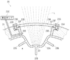
始めに、第1の実施形態に係る太陽炉装置10の構成について、図1ないし図3を用いて説明する。この太陽炉装置10は、図2に示すように、太陽光線Lを直達光集光レンズ14、反射光集光レンズ15および平面鏡16(すなわち集光手段)により集光してケーシング11の受光部12に受光させるようになっている。受光部12は、受光した太陽光線Lから熱エネルギーを取り出し、ケーシング11内の水wを加熱するようになっている。ここで、水wが本発明における「熱媒体」に相当する。
EMBODIMENT OF THE INVENTION Below, the form for implementing this invention is demonstrated using drawing.
<First Embodiment>
First, the configuration of the
上記水wは、図1に示すように、まず水源Wから液体の状態で水タンクT2に供給されて蓄えられ、この水タンクT2から太陽炉装置10に供給される。ついで、水wは、太陽炉装置10により加熱されてその状態が高圧の蒸気(または超臨界流体)に変化し、この状態で蒸気タンクT1に供給されて蓄えられる。蒸気タンクT1に蓄えられた水wは、原動機Pを駆動させてその状態が低圧の蒸気に変化する。
なお、本実施形態においては、原動機Pは蒸気機関であり、その駆動力は発電機Gによる発電に用いられる。また、原動機Pを駆動させた後の水wは、その一部が復水器Cにより液体の状態で回収されて水タンクT2に戻される。これにより、水源Wから供給する水wの量を減らすとともに、原動機Pを駆動させた後の水wが持つ熱エネルギーの一部を回収することができる。
As shown in FIG. 1, the water w is first supplied from the water source W to the water tank T2 in a liquid state and stored, and is supplied from the water tank T2 to the
In the present embodiment, the prime mover P is a steam engine, and its driving force is used for power generation by the generator G. A part of the water w after driving the prime mover P is recovered in a liquid state by the condenser C and returned to the water tank T2. Thereby, while reducing the quantity of the water w supplied from the water source W, a part of thermal energy which the water w after driving the motor | power_engine P can be collect | recovered.
受光部12は、長尺の直管形状に形成されてその長手方向(図1で見て上下方向)に水wを流通させるようになっている。この受光部12は、長尺の直管形状に形成されたケーシング11の内部に、ケーシング11の長手方向(図1で見て上下方向)に沿うように配設されている。
受光部12は、図3に示すように、集光された太陽光線Lを受光して発熱し、その熱を受光部12の表面に沿った方向(熱移動方向H1を参照)に熱伝導させながら水wを加熱する(熱移動方向H2を参照)ように構成されている。このため、受光部12はその内部の水wをより均一に加熱することができる。
The
As shown in FIG. 3, the
ここで、受光部12には、図2に示すように、複数本(本実施形態では3本)の受光溝12Aが形成されている。そして、受光部12は、上記各受光溝12Aにより太陽光線Lを受光するように構成されている。これにより、受光部12が水wに接触する面積が増加し、受光部12が水wを加熱する際のエネルギー効率が向上する。なお、各受光溝12Aは、受光部12の直管を、その表面側からその長手方向(図1で見て上下方向)に沿って長尺の直線状に凹ませることで形成されている。
上記各受光溝12Aは、図3に示すように、その溝の底が集光される太陽光線Lに対して垂直になるように湾曲している。これにより、各受光溝12Aにおける太陽光線Lの反射を低減させて、太陽炉装置10のエネルギー回収効率を向上させることができる。また、各受光溝12Aは、受光部12の内部側(図3で見て下側)に向かって板状に形成された複数枚(本実施形態では3枚)の放熱器12Bを備えている。これにより、受光部12が水wに接触する面積が増加し、受光部12が水wを加熱する際のエネルギー効率が向上する。
Here, as shown in FIG. 2, a plurality of
As shown in FIG. 3, each of the
ケーシング11は、図2および図3に示すように、ケーシング11の内面に形成された断熱層11Aと、ケーシング11の内部に太陽光線Lを導いて上記受光部12に受光させる窓部13と、を備えている。
断熱層11Aは、図3に示すように、受光部12を外側から覆うように配設されて、この受光部12から外部に向かう方向(熱移動方向H3を参照)の熱移動を遮断するように構成されている。これにより、受光部12から外部に逃げる熱エネルギーの量を低減させて、太陽炉装置10のエネルギー回収効率を向上させることができる。
窓部13は、図1ないし図3に示すように、上記断熱層11Aの複数箇所(本実施形態では3箇所、図2参照)にケーシング11の長手方向(図1で見て上下方向)に沿って開けられた長孔形状に形成されている。ここで、各窓部13は、受光部12の各受光溝12Aに対応した位置に形成されて、受光部12が各受光溝12Aで太陽光線Lを受光できるようになっている。
As shown in FIGS. 2 and 3, the
As shown in FIG. 3, the
As shown in FIGS. 1 to 3, the
上記各窓部13には、それぞれ透明部材13Aが嵌め込まれている。この各透明部材13Aは、光を透過させ、かつ、各窓部13を介した物質の出入りを遮断するように構成されている。これにより、物質の対流および拡散により各窓部13から受光部12の熱エネルギーが失われることを防いで、太陽炉装置10のエネルギー回収効率を向上させることができる。
透明部材13Aは、図3に示すように、その内部に真空層13Bを備えている。このため、透明部材13Aは、光を透過させる性質を保ったまま、その熱伝導率が低減されている。言い換えると、各窓部13は、この各窓部13を介した熱伝導を各真空層13Bにより低減させるようになっている。そして、各真空層13Bは、それぞれ透明部材13Aという1つの部材の内部に形成されている。
これにより、受光部12に集光される太陽光線Lを遮断することなく、透明部材13Aを介した熱伝導による熱エネルギーの損失を防いで、太陽炉装置10のエネルギー回収効率を向上させることができる。また、透明部材13Aの気密性を高めることで真空層13Bの維持を簡単にして、太陽炉装置10の構成を簡単にすることができる。
A
As shown in FIG. 3, the
Thereby, the loss of thermal energy due to heat conduction through the
ここで、太陽炉装置10の集光手段について説明する。太陽炉装置10の集光手段は、図1および図2に示すように、太陽光線Lの直達光線を受光部12に集光させる直達光集光レンズ14と、太陽光線Lをケーシング11に向けて反射させる一対の平面鏡16と、この各平面鏡16により反射された太陽光線Lを受光部12に集光させる一対の反射光集光レンズ15と、で構成されている。
ところで、鏡の鏡面に凹みがある場合も、その凹んだ鏡面により反射光を集光させることができる。しかしながら、この場合は、鏡面と入射光の角度関係によっては、鏡面の凹みにより生じる陰が鏡面の他の部分に落ちることで、その部分の鏡面が入射光を反射しなくなる。言い換えると、太陽炉装置の集光手段において、その鏡の鏡面に凹みがある場合、その鏡面と太陽との角度関係によっては、集光手段の集光能力が低下する可能性が生じる。
すなわち、上記構成によれば、平面鏡16で反射した太陽光線Lを反射光集光レンズ15により受光部12に集光させることで、鏡の鏡面に陰が落ちて集光能力が低下することを防ぐことができる。さらに、鏡の製造コストを抑えて太陽炉装置10をより安価にすることができる。
Here, the condensing means of the
By the way, even when there is a dent in the mirror surface of the mirror, the reflected light can be collected by the concave mirror surface. However, in this case, depending on the angular relationship between the mirror surface and the incident light, the shade caused by the recess of the mirror surface falls to other portions of the mirror surface, so that the mirror surface of that portion does not reflect the incident light. In other words, in the light collecting means of the solar furnace device, when the mirror surface of the mirror has a dent, the light collecting ability of the light collecting means may be reduced depending on the angular relationship between the mirror surface and the sun.
That is, according to the above configuration, the sunlight ray L reflected by the
なお、直達光集光レンズ14を通った太陽光線Lと各反射光集光レンズ15を通った太陽光線Lは、図2に示すように、それぞれ別々の光路を通って別々の窓部13から受光部12に導かれるようになっている。
このため、窓部13を、直達光集光レンズ14および平面鏡16と反射光集光レンズ15の組がそれぞれ集光する太陽光線Lの光路に対応させて配設することで、直達光集光レンズ14、平面鏡16、および、反射光集光レンズ15の配設をしやすくすることができる。
In addition, as shown in FIG. 2, the sunlight ray L which passed the direct
For this reason, the direct light collection is performed by arranging the
上記直達光集光レンズ14および各反射光集光レンズ15は、図1および図2に示すように、その曲率方向と垂直な方向に長尺な(図1参照)平凸のシリンドリカルレンズ(図2参照)として形成されている。そして、この各レンズ14、15は、その平面側を窓部13に向けた状態で(図2参照)、その長手方向がケーシング11の長手方向(図1で見て上下方向)に沿うように配設されている。なお、上記各平面鏡16は、図1に示すように、長尺に形成されて、その長手方向がケーシング11の長手方向(図示上下方向)に沿うように配設されている。
As shown in FIGS. 1 and 2, the direct
太陽光線Lは一般的に平行光線とみなすことができる。ここで、平面鏡には、平行光線を平行光線として反射するという性質がある。また、シリンドリカルレンズには、その曲率方向と垂直な方向には集光も光の拡散も行わないという性質がある。さらに、平凸のシリンドリカルレンズには、その凸面側から平行光線を入射させると、この平行光線をシリンドリカルレンズの平面側に線分形状に集光(結像)させるという性質がある。ここで、上記集光による線分は、その向きが上記シリンドリカルレンズの曲率方向に対して垂直になるように結像される。 Sun rays L can generally be regarded as parallel rays. Here, the plane mirror has a property of reflecting parallel rays as parallel rays. In addition, the cylindrical lens has a property that neither light collection nor light diffusion is performed in a direction perpendicular to the curvature direction. Further, the plano-convex cylindrical lens has a property that when a parallel light beam is incident from the convex surface side, the parallel light beam is condensed (imaged) on the plane side of the cylindrical lens. Here, the line segment resulting from the light collection is imaged so that its direction is perpendicular to the direction of curvature of the cylindrical lens.
上述した各構成により、図2に示すように、直達光集光レンズ14に入射した太陽光線Lを、長孔形状に形成された窓部13を通して長尺の直線状に形成された受光溝12Aに集光させることができる。また、各平面鏡16により太陽光線Lを平行光線の状態で反射して各反射光集光レンズ15に入射させ、長孔形状に形成された窓部13を通して長尺の直線状に形成された受光溝12Aに集光させることができる。
このため、太陽炉装置10は、長尺の直管形状に形成された受光部12の長手方向(図1で見て上下方向)に水wを連続的に流通させながら、この水wを連続的に加熱することができる。これにより、太陽炉装置10は、太陽光線Lから効率的に熱エネルギーを取り出すことができる。
As shown in FIG. 2, the
For this reason, the
ところで、第1の実施形態の太陽炉装置10は、図2に示すように、太陽を追尾することで太陽炉装置10のエネルギー回収効率を向上させる太陽光追尾装置17を備えている。この太陽光追尾装置17は、地面に対して一体に固定された基台17Aと、支柱11Bを介してケーシング11が一体に固定された設置台17Bと、この設置台17Bを基台17Aに対して傾動可能に連結させるジャッキ17Fと、このジャッキ17Fに駆動力を与えて設置台17Bを傾動させる複数のモーター17Dと、この各モーター17Dを制御して設置台17Bを傾動させ、そのケーシング11が固定された側の設置面17Cを太陽に向ける制御装置17Eと、を備えている。
ここで、直達光集光レンズ14は、支柱14Aによりケーシング11に対して一体に固定されている。また、各反射光集光レンズ15は、それぞれ支柱15Aにより設置台17Bの設置面17C側に一体に固定されている。また、各平面鏡16は、それぞれ支柱16Aにより設置台17Bの設置面17C側に一体に固定されている。
By the way, the
Here, the direct
上記構成により、太陽光追尾装置17は、設置台17Bの設置面17Cを、ケーシング11および太陽炉装置10の集光手段(すなわち、直達光集光レンズ14、反射光集光レンズ15および平面鏡16)と一体に太陽に向けるようになっている。言い換えると、太陽炉装置10の集光手段の各構成は、ケーシング11およびその内部の受光部12と一体に太陽を追尾する。
このため、太陽光線Lを集光させる際に集光手段の各構成を個別に制御する必要がなくなり、太陽炉装置10の構成が簡単になる。また、ケーシング11および集光手段に当たる太陽光線Lの角度が一定となるので、ケーシング11およびその支柱11Bにより遮られる範囲の太陽光線を直達光集光レンズ14により集光することができる。さらに、太陽炉装置10の集光手段の各支柱14A、15A、16Aを太陽光線Lと干渉しない位置に配設して、太陽炉装置10の集光能力の低下を防止することができる。
With the above-described configuration, the solar light tracking device 17 uses the installation surface 17C of the installation table 17B as the condensing means (that is, the direct
For this reason, when condensing the sunlight L, it is not necessary to individually control each component of the condensing means, and the configuration of the
〈第2の実施形態〉
続いて、第2の実施形態に係る太陽炉装置20の構成について、図4を用いて説明する。第2の実施形態に係る太陽炉装置20は、第1の実施形態に係る太陽炉装置10を変形した実施形態である。したがって、上記第1の実施形態に係る太陽炉装置10の各構成と共通する構成については、第1の実施形態に係る太陽炉装置10の各構成に付した符号から、その十の位の数字を「2」に置き換えた符号を付して対応させ、その詳細な説明を省略する。
第2の実施形態の太陽炉装置20は、図4に示すように、窓部23の真空層23Bを、透明部材23Aと受光部22との間に配設したものである。言い換えると、上記真空層23Bは、透明部材23Aと受光部22との間の空気を真空ポンプ23Cおよび排気管23Dにより排気することで形成される。ここで、何らかの理由により透明部材23Aと受光部22との間の空間に空気が入り込むと、上記真空層23Bは失われる。この場合、上述した真空ポンプ23Cを再駆動させて入り込んだ空気を排気することで、真空層23Bを再び形成することができる。
上記構成によれば、窓部23を介した熱伝導を真空層23Bにより低減させて、太陽炉装置20のエネルギー回収効率を向上させることができる。さらに、透明部材23Aの製造コストを抑えて太陽炉装置20をより安価にすることができる。
<Second Embodiment>
Then, the structure of the
In the
According to the said structure, the heat conduction through the
ここで、窓部23は、その窓枠23Eが金属により形成されて受光部22に対して一体に熔接されている。また、この窓枠23Eには、板状に形成された透明部材23Aがガスケット23Fを挟んだ状態でボルト23Gにより固定されている。これにより、透明部材23Aと受光部22との間の空間に気密性を持たせて、真空層23Bを維持することができる。
なお、上記太陽炉装置20においては、受光部22から窓枠23Eおよびボルト23Gを介して外部に逃げる熱量は無視できるほど小さいとみなしている。しかしながら、窓枠23Eおよびボルト23Gを熱伝導率の小さい素材で形成したり、ボルト23Gの頭部を断熱材で覆ったりすることで、太陽炉装置20のエネルギー回収効率をさらに向上させることもできる。
Here, the
In the
本発明は、上述した第1および第2の実施形態で説明した外観、構成に限定されず、本発明の要旨を変更しない範囲で種々の変更、追加、削除が可能である。例えば、以下のような各種の形態を実施することができる。
(1)直達光集光レンズおよび反射光集光レンズの形状は平凸のシリンドリカルレンズに限定されず、例えばトーリックレンズなど適宜設定することができる。また、各レンズをフレネルレンズとして各レンズの軽量化を図ることもできる。
(2)太陽炉装置の集光手段としてレンズを用いる必要はなく、例えば凹面鏡により太陽光線を集光する構成を用いることができる。
(3)太陽炉装置から集光手段を省略することができる。
(4)太陽光追尾装置が太陽炉装置の集光手段を個別に制御して動かす構成を用いることができる。
(5)太陽炉装置から太陽光追尾装置を省略することができる。
(6)熱媒体の流通経路は受光部の内部に限定されず、受光部から熱エネルギーを伝えることができ、かつ、ケーシングにより外部に逃げる熱エネルギーを低減させることができる流通経路を適宜設定することができる。
(7)太陽炉装置に流通させる熱媒体は水に限定されず、流通可能な流体を適宜設定することができる。
(8)太陽炉装置に熱媒体を流通させる必要はなく、例えば受光部に熱伝導率の高い金属を連結させて、この金属からの熱伝導により熱エネルギーを取り出す構成を用いることができる。
(9)放熱器の形状および配置は第1および第2の実施形態の形状に限定されない。すなわち、例えば放熱器を棒状に形成することができる。また、放熱器を他の放熱器または受光部の内壁面に接続させて、この放熱器に受光部の強度を高める支柱としての機能を追加して持たせることもできる。
(10)受光部の放熱器および受光溝は、それぞれ省略することができる。
(11)窓部およびケーシングの形状および配置は第1および第2の実施形態の形状に限定されず、円形の窓部を1つだけ配置するなど、太陽炉装置の各構成の形状および配置に合わせて適宜変更することができる。
(12)太陽炉装置により駆動される原動機は蒸気機関に限定されず、蒸気タービンなど任意の熱機関を用いることができる。
(13)太陽炉装置は原動機を駆動させて発電機により発電を行うものに限定されず、例えば熱電変換部材により熱エネルギーを直接電気エネルギーに変換する構成を用いることができる。また、原動機の駆動力を直接利用する構成や、熱エネルギーを直接化学反応に利用する構成を用いることもできる。
The present invention is not limited to the appearance and configuration described in the first and second embodiments described above, and various modifications, additions, and deletions can be made without changing the gist of the present invention. For example, the following various forms can be implemented.
(1) The shapes of the direct light condensing lens and the reflected light condensing lens are not limited to plano-convex cylindrical lenses, and can be set as appropriate, for example, a toric lens. Further, each lens can be reduced in weight by using each lens as a Fresnel lens.
(2) It is not necessary to use a lens as the condensing means of the solar furnace device, and for example, a configuration in which sunlight rays are condensed by a concave mirror can be used.
(3) The light collecting means can be omitted from the solar furnace device.
(4) A configuration in which the solar light tracking device individually controls and moves the light collecting means of the solar furnace device can be used.
(5) The solar light tracking device can be omitted from the solar furnace device.
(6) The distribution path of the heat medium is not limited to the inside of the light receiving section, and a distribution path that can transmit heat energy from the light receiving section and can reduce the heat energy that escapes to the outside by the casing is appropriately set. be able to.
(7) The heat medium distributed to the solar furnace device is not limited to water, and a fluid that can be distributed can be set as appropriate.
(8) It is not necessary to circulate the heat medium in the solar furnace device. For example, a structure in which a metal having high thermal conductivity is connected to the light receiving unit and heat energy is extracted by heat conduction from the metal can be used.
(9) The shape and arrangement of the radiator are not limited to the shapes of the first and second embodiments. That is, for example, the radiator can be formed in a rod shape. Further, the radiator can be connected to another radiator or the inner wall surface of the light receiving portion, and this radiator can be additionally provided with a function as a support column for increasing the strength of the light receiving portion.
(10) The radiator and the light receiving groove of the light receiving unit can be omitted.
(11) The shape and arrangement of the window portion and the casing are not limited to the shapes of the first and second embodiments. For example, only one circular window portion is arranged. It can be changed as appropriate.
(12) The prime mover driven by the solar furnace device is not limited to the steam engine, and any heat engine such as a steam turbine can be used.
(13) The solar furnace device is not limited to the one that drives the prime mover and generates power with the generator. For example, a configuration in which thermal energy is directly converted into electric energy by a thermoelectric conversion member can be used. Moreover, the structure which utilizes directly the driving force of a motor | power_engine, or the structure which utilizes heat energy for a chemical reaction directly can also be used.
10 太陽炉装置
11 ケーシング
11A 断熱層
11B 支柱
12 受光部
12A 受光溝
12B 放熱器
13 窓部
13A 透明部材
13B 真空層
14 直達光集光レンズ
14A 支柱
15 反射光集光レンズ
15A 支柱
16 平面鏡
16A 支柱
17 太陽光追尾装置
17A 基台
17B 設置台
17C 設置面
17D モーター
17E 制御装置
17F ジャッキ
20 太陽炉装置
21 ケーシング
21A 断熱層
22 受光部
22A 受光溝
22B 放熱器
23 窓部
23A 透明部材
23B 真空層
23C 真空ポンプ
23D 排気管
23E 窓枠
23F ガスケット
23G ボルト
C 復水器
G 発電機
H1 熱移動方向
H2 熱移動方向
H3 熱移動方向
L 太陽光線
P 原動機
T1 蒸気タンク
T2 水タンク
W 水源
w 水(熱媒体)
DESCRIPTION OF
Claims (3)
前記受光部は、内面に断熱層が形成されたケーシングの内部に配設されて、前記太陽光線の受光により生じた熱によって、前記ケーシング内の熱媒体を当該熱媒体に接触することで加熱し、
前記ケーシングは、当該ケーシングの内部に前記太陽光線を導いて当該太陽光線を前記受光部に受光させる窓部を備え、
前記窓部は、当該窓部を介した物質の出入りを遮断する透明部材と、前記窓部を介した熱伝導を低減させる真空層と、を備え、
前記受光部には、前記熱媒体に接触される面を当該熱媒体側に向けて突出させた受光溝が形成され、
前記受光溝は、前記窓部により導かれた前記太陽光線に対して垂直となるように配設された面と、この面に向かう前記太陽光線に沿うように延びることで当該太陽光線を遮断しないように配設された面とを備えて、前記受光部が前記熱媒体に接触して当該熱媒体を加熱する面の面積を増加させていることを特徴とする太陽炉装置。 It is a solar furnace device equipped with a light receiving part for receiving solar rays and taking out thermal energy,
The light receiving unit is disposed inside a casing having a heat insulating layer formed on an inner surface thereof , and heats the heat medium in the casing by contacting the heat medium with heat generated by receiving the sunlight. ,
The casing includes a window portion that guides the sunlight into the casing and causes the light receiver to receive the sunlight.
The window portion includes a transparent member that blocks entry and exit of a substance through the window portion, and a vacuum layer that reduces heat conduction through the window portion ,
In the light receiving part, a light receiving groove is formed by projecting a surface in contact with the heat medium toward the heat medium side,
The light receiving groove does not block the sunlight by extending along the surface arranged so as to be perpendicular to the sunlight guided by the window and along the sunlight toward the surface. The solar furnace device is characterized in that the area of the surface on which the light receiving unit is in contact with the heat medium and heats the heat medium is increased .
前記受光溝は、前記受光部が前記熱媒体に接触する側に向かって板状あるいは棒状に形成された複数の放熱器を備えていることを特徴とする太陽炉装置。 It is a solar furnace apparatus of Claim 1, Comprising:
The said light-receiving groove | channel is equipped with the several heat radiator formed in plate shape or rod shape toward the side where the said light-receiving part contacts the said heat medium, The solar furnace apparatus characterized by the above-mentioned.
前記受光部は、内壁面を有する管形状に形成されて、その内部の前記熱媒体に接触して当該熱媒体を加熱し、前記放熱器は、前記受光部において当該受光部が前記熱媒体に接触する内部側に形成された他の前記放熱器または前記受光部の前記内壁面に接続されていることを特徴とする太陽炉装置。 It is a solar furnace apparatus of Claim 2 , Comprising:
The light receiving unit is formed in a tube shape having an inner wall surface, and contacts the heat medium inside to heat the heat medium, and the radiator is configured such that the light receiving unit is the heat medium in the light receiving unit. A solar furnace device, wherein the solar furnace device is connected to the other heat radiator formed on the inner side in contact with the inner wall surface of the light receiving unit .
Priority Applications (1)
| Application Number | Priority Date | Filing Date | Title |
|---|---|---|---|
| JP2011232669A JP5653885B2 (en) | 2011-10-24 | 2011-10-24 | Solar furnace equipment |
Applications Claiming Priority (1)
| Application Number | Priority Date | Filing Date | Title |
|---|---|---|---|
| JP2011232669A JP5653885B2 (en) | 2011-10-24 | 2011-10-24 | Solar furnace equipment |
Publications (2)
| Publication Number | Publication Date |
|---|---|
| JP2013092266A JP2013092266A (en) | 2013-05-16 |
| JP5653885B2 true JP5653885B2 (en) | 2015-01-14 |
Family
ID=48615535
Family Applications (1)
| Application Number | Title | Priority Date | Filing Date |
|---|---|---|---|
| JP2011232669A Active JP5653885B2 (en) | 2011-10-24 | 2011-10-24 | Solar furnace equipment |
Country Status (1)
| Country | Link |
|---|---|
| JP (1) | JP5653885B2 (en) |
Family Cites Families (5)
| Publication number | Priority date | Publication date | Assignee | Title |
|---|---|---|---|---|
| JPS5366027A (en) * | 1976-11-26 | 1978-06-13 | Hitachi Ltd | Solar heat collector |
| WO1983001292A1 (en) * | 1981-10-01 | 1983-04-14 | Tor Ask | Apparatus for collecting solar energy |
| US4644933A (en) * | 1985-10-28 | 1987-02-24 | Gregory Samuel T | Solar system |
| JP2009264670A (en) * | 2008-04-25 | 2009-11-12 | Nippon Telegr & Teleph Corp <Ntt> | Solar energy collector and solar energy collecting system |
| JP2011027268A (en) * | 2008-08-07 | 2011-02-10 | Takashi Yabe | High efficiency sunlight tracking and heat collecting apparatus, desalination apparatus, and generator |
-
2011
- 2011-10-24 JP JP2011232669A patent/JP5653885B2/en active Active
Also Published As
| Publication number | Publication date |
|---|---|
| JP2013092266A (en) | 2013-05-16 |
Similar Documents
| Publication | Publication Date | Title |
|---|---|---|
| US8430093B1 (en) | Solar collector using subreflector | |
| US8418464B2 (en) | Linear solar heat generating system | |
| US20010054252A1 (en) | Light element with a translucent surface | |
| KR101331623B1 (en) | Structure of combined solar thermal and solar photovoltaic system | |
| US9279416B2 (en) | Solar power system | |
| US10072875B2 (en) | Heat concentrator device for solar power system | |
| JP2013096676A (en) | Solar energy conversion device | |
| WO2009045141A1 (en) | Solar concentrator | |
| WO2014013782A1 (en) | Solar thermal power generation device | |
| KR20100101325A (en) | Heating exchanger using solar heat and heating apparatus thereof | |
| CN102803723B (en) | Tower For Solar Concentration Plant With Natural Draught Cooling | |
| JP2014052153A (en) | Solar heat collection device | |
| JP5653885B2 (en) | Solar furnace equipment | |
| KR101404375B1 (en) | Solar heating system | |
| KR102358978B1 (en) | Parabolic trough concentrator type solar thermal energy system having concentrated photovoltaic | |
| KR102030850B1 (en) | Solar Energy Hybrid Generation System, And Hydrogen Production System Having The Same | |
| JP2013105927A (en) | Power generating facility utilizing solar energy and operational method thereof | |
| JP3172797U (en) | Sunlight collector | |
| KR100920796B1 (en) | Thermal storage unit using electron wave of solar radiation | |
| CN105758014B (en) | A kind of heat dump of linear Fresnel collecting system | |
| KR20100008996A (en) | Solar compound parabolic conentrator | |
| KR100365771B1 (en) | Upgradable concentration ratio CPC(Compound parabolic concentrator) compared with acceptance angle and manufacturing method of the same | |
| JP6042375B2 (en) | Condensing thermal boiler equipment using solar energy | |
| JP2011087416A (en) | Solar thermal power generator | |
| JP2017153217A (en) | Power generator |
Legal Events
| Date | Code | Title | Description |
|---|---|---|---|
| A621 | Written request for application examination |
Free format text: JAPANESE INTERMEDIATE CODE: A621 Effective date: 20130619 |
|
| A977 | Report on retrieval |
Free format text: JAPANESE INTERMEDIATE CODE: A971007 Effective date: 20140423 |
|
| A131 | Notification of reasons for refusal |
Free format text: JAPANESE INTERMEDIATE CODE: A131 Effective date: 20140430 |
|
| A521 | Request for written amendment filed |
Free format text: JAPANESE INTERMEDIATE CODE: A523 Effective date: 20140602 |
|
| TRDD | Decision of grant or rejection written | ||
| A01 | Written decision to grant a patent or to grant a registration (utility model) |
Free format text: JAPANESE INTERMEDIATE CODE: A01 Effective date: 20141111 |
|
| A61 | First payment of annual fees (during grant procedure) |
Free format text: JAPANESE INTERMEDIATE CODE: A61 Effective date: 20141119 |
|
| R150 | Certificate of patent or registration of utility model |
Ref document number: 5653885 Country of ref document: JP Free format text: JAPANESE INTERMEDIATE CODE: R150 |
|
| R250 | Receipt of annual fees |
Free format text: JAPANESE INTERMEDIATE CODE: R250 |
|
| R250 | Receipt of annual fees |
Free format text: JAPANESE INTERMEDIATE CODE: R250 |
|
| R250 | Receipt of annual fees |
Free format text: JAPANESE INTERMEDIATE CODE: R250 |