JP5653314B2 - Color image forming apparatus - Google Patents
Color image forming apparatus Download PDFInfo
- Publication number
- JP5653314B2 JP5653314B2 JP2011164992A JP2011164992A JP5653314B2 JP 5653314 B2 JP5653314 B2 JP 5653314B2 JP 2011164992 A JP2011164992 A JP 2011164992A JP 2011164992 A JP2011164992 A JP 2011164992A JP 5653314 B2 JP5653314 B2 JP 5653314B2
- Authority
- JP
- Japan
- Prior art keywords
- image
- detection
- electrostatic latent
- forming apparatus
- image forming
- Prior art date
- Legal status (The legal status is an assumption and is not a legal conclusion. Google has not performed a legal analysis and makes no representation as to the accuracy of the status listed.)
- Expired - Fee Related
Links
Images


Description
本発明は、電子写真方式を用いたカラー画像形成装置に関する。 The present invention relates to a color image forming apparatus using an electrophotographic system.
電子写真方式のカラー画像形成装置では、高速に印刷するために、各色の画像形成部を独立して有し、各色の画像形成部から順次中間転写ベルトに画像を転写し、更に中間転写ベルトから記録媒体に一括して画像を転写する構成が知られている。 In an electrophotographic color image forming apparatus, in order to print at high speed, each color image forming unit is independently provided, and images are sequentially transferred from the image forming unit of each color to the intermediate transfer belt, and further from the intermediate transfer belt. A configuration is known in which images are collectively transferred to a recording medium.
この様なカラー画像形成装置では、各色の画像形成部における機械的要因により、画像を重ね合わせたときに色ずれ(位置ずれ)を生じる問題が発生する。特に、レーザスキャナ(光学走査装置)と感光体ドラムを各色の画像形成部に独立して有する構成では、レーザスキャナと感光体ドラムの位置関係が各色毎に異なってしまい、感光体ドラム上のレーザの走査位置の同期を取れず、色ずれを生じてしまう。 In such a color image forming apparatus, there arises a problem that color misregistration (positional misregistration) occurs when images are overlapped due to mechanical factors in the image forming unit of each color. In particular, in a configuration having a laser scanner (optical scanning device) and a photosensitive drum independently in each color image forming unit, the positional relationship between the laser scanner and the photosensitive drum is different for each color, and the laser on the photosensitive drum. The scanning positions cannot be synchronized, and color misregistration occurs.
そして、これらの色ずれを補正するために、上記のようなカラー画像形成装置では、色ずれ補正制御が行なわれている。特許文献1では、感光ドラムから像担持体上(中間点転写ベルト等)に各色の検出用トナー像を転写し、検出用トナー像の走査方向および搬送方向の相対位置を、光学センサを用いて検出することにより色ずれ補正制御を行っている。 In order to correct these color misregistrations, color misregistration correction control is performed in the color image forming apparatus as described above. In Patent Document 1, a detection toner image of each color is transferred from a photosensitive drum onto an image carrier (such as an intermediate transfer belt), and the relative position of the detection toner image in the scanning direction and the conveyance direction is measured using an optical sensor. By detecting this, color misregistration correction control is performed.
しかしながら、従来から知られている色ずれ補正制御には、以下の課題があった。感光ドラムから像担持体(ベルト)に、色ずれ補正制御における検出用トナー像(100%濃度)を転写するので、像担持体のクリーニング等に時間を要してしまい、画像形成装置のユーザビリティーを低下させてしまう。 However, conventionally known color misregistration correction control has the following problems. Since the toner image for detection (100% density) in color misregistration correction control is transferred from the photosensitive drum to the image carrier (belt), it takes time to clean the image carrier and the usability of the image forming apparatus. Will be reduced.
本発明は、上記課題に鑑みてなされたものであり、画像形成装置のユーザビリティーを持たせつつ、色ずれ補正制御を行えるようにすることを目的とする。 SUMMARY An advantage of some aspects of the invention is that color misregistration correction control can be performed while maintaining the usability of an image forming apparatus.
前述の課題を解決するために、本願発明は以下の構成を備える。
回転駆動される感光体と、前記感光体の周囲に配置され前記感光体に作用するプロセス手段と、光を照射することで前記感光体に静電潜像を形成する光照射手段とを有し、前記光照射手段は前記感光体に検出用の静電潜像を形成可能な画像形成装置において、前記プロセス手段に電力を供給する電源手段と、前記光照射手段が、前記感光体に光を照射し検出用の静電潜像を形成するタイミングを基に、前記検出用の静電潜像が前記プロセス手段に対向する位置を通過する際の前記プロセス手段を介して生じる前記電源手段の出力が検出されるまでの時間を検出する検出手段と、前記検出手段からの検出結果に基づき、画像形成時の静電潜像を形成する位置を補正する制御手段と、を備えることを特徴とする画像形成装置。
In order to solve the above problems, the present invention has the following configuration.
A rotationally driven photoreceptor, process means disposed around the photoreceptor and acting on the photoreceptor, and light irradiation means for forming an electrostatic latent image on the photoreceptor by irradiating light. In the image forming apparatus capable of forming a detection electrostatic latent image on the photoconductor, the light irradiation unit is configured to supply power to the process unit, and the light irradiation unit emits light to the photoconductor. The output of the power supply means generated through the process means when the electrostatic latent image for detection passes through a position facing the process means based on the timing of forming an electrostatic latent image for detection by irradiation. And a control means for correcting a position where an electrostatic latent image is formed at the time of image formation based on a detection result from the detection means. Image forming apparatus.
本発明によれば、画像形成装置のユーザビリティーを持たせつつ、色ずれ補正制御を行える。 According to the present invention, color misregistration correction control can be performed while maintaining the usability of the image forming apparatus.
以下に、図面を参照して、この発明の好適な実施の形態を例示的に詳しく説明する。ただし、この実施の形態に記載されている構成要素はあくまで例示であり、この発明の範囲をそれらのみに限定する趣旨のものではない。 Hereinafter, exemplary embodiments of the present invention will be described in detail with reference to the drawings. However, the constituent elements described in this embodiment are merely examples, and are not intended to limit the scope of the present invention only to them.
以下に、図面を参照して、この発明の好適な実施の形態を例示的に詳しく説明する。ただし、この実施の形態に記載されている構成要素はあくまで例示であり、この発明の範囲をそれらのみに限定する趣旨のものではない。 Hereinafter, exemplary embodiments of the present invention will be described in detail with reference to the drawings. However, the constituent elements described in this embodiment are merely examples, and are not intended to limit the scope of the present invention only to them.
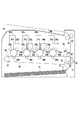
[インライン方式(4ドラム系)のカラー画像形成装置の構成図]
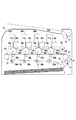
図1はインライン方式(4ドラム系)のカラー画像形成装置10の構成図である。ピックアップローラ13によって繰り出された記録媒体12は、レジストセンサ11によって先端位置が検出された後、搬送ローラ対14,15に先端が少し通過した位置で搬送を一旦停止される。
[Configuration diagram of in-line (4-drum) color image forming apparatus]
FIG. 1 is a configuration diagram of a color
一方、スキャナユニット20a〜20dは、回転駆動される感光体ドラム22a〜22dに順次レーザ光21a〜21dを照射する。この時、感光体ドラム22a〜22dは、帯電ローラ23a〜23dによって予め帯電されているので、前記レーザ光21a〜21dの照射によって静電潜像を形成する。現像器25a〜25dおよび現像スリーブ24a〜24dは、感光体ドラム22a〜22dの静電潜像にトナーを載せ、トナー像を形成する。1次転写ローラ26a〜26dは、感光体ドラム22a〜22dのトナー像を、中間転写ベルト30に転写する。尚、スキャナユニット及び感光ドラムを含む、帯電ローラ、現像器及び1次転写ローラのトナー像を形成するのに直接的に係る部材群のことを画像形成部と称する。場合によってはスキャナユニット20を含めずに画像形成部と称しても良い。また、感光ドラムの周囲に近接して配置され、感光ドラムに作用する各部材(帯電ローラ、現像器及び1次転写ローラ)のことを、プロセス手段と称する。
On the other hand, the
中間転写ベルト30は、ローラ31,32,33によって周回駆動され、トナー像を2次転写ローラ27の位置へ搬送する。この時、記録媒体12は2次転写ローラ27の位置で搬送されたトナー像とタイミングが合うよう搬送が再開され、2次転写ローラ27によって中間転写ベルト30からトナー像を転写される。
The
その後、定着ローラ対16,17によって記録媒体12のトナー像を加熱定着した後、記録媒体12を機外へ出力する。ここで、2次転写ローラ27によって、中間転写ベルト30から記録媒体12へ転写されなかったトナーは、クリーニングブレード35によって廃トナー容器36に回収される。また、色ずれ検出センサ40の動作については後述する。ここで、各符号の英文字aはイエロー、bはマゼンタ、cはシアン、dはブラックの構成およびユニットを示す。
Thereafter, the toner image on the
[高圧電源装置の構成図]
次に、図2を用いて図1の画像形成装置における高圧電源装置の構成を説明する。高圧電源回路装置は、帯電高圧電源回路43、現像高圧電源回路44a〜44d、1次転写高圧電源回路46a〜46d、2次転写高圧電源回路48を備えている。帯電高圧電源回路43は、帯電ローラ23a〜23dに印加することで、感光体ドラム22a〜22dの表面にバックグラウンド電位を形成し、レーザ光の照射によって静電潜像を形成可能な状態にする。現像高圧電源回路44a〜44dは、現像スリーブ24a〜24dに印加することで、感光体ドラム22a〜22dの静電潜像にトナーを載せ、トナー像を形成する。1次転写高圧電源回路46a〜46dは、1次転写ローラ26a〜26dに印加することで、感光体ドラム22a〜22dのトナー像を中間転写ベルト30に転写する。2次転写高圧電源回路48は、2次転写ローラ27に印加することで、中間転写ベルト30のトナー像を記録媒体12へ転写する。また、1次転写高圧電源回路46a〜46dは、電流検出回路47a〜47dを備えている。これは、1次転写ローラ26a〜26dにおけるトナー像の転写性能が、1次転写ローラ26a〜26dに流れる電流量に応じて変化するためである。電流検出回路47a〜47dの検出結果に応じて1次転写ローラ26a〜26dに印加するバイアス電圧(高圧)を調整し、装置内の温度や湿度が変化しても転写性能を一定に保つよう構成されている。尚、1次転写中には、この1次転写ローラ26a〜26dに流れる電流量が目標値になるようにして設定されたバイアス電圧を目標にして定電圧制御が行われる。
[Configuration diagram of high-voltage power supply unit]
Next, the configuration of the high-voltage power supply device in the image forming apparatus of FIG. 1 will be described with reference to FIG. The high-voltage power supply circuit device includes a charging high-voltage
[プリンタシステムのハードウェアブロック図]
次に、図3を用いてプリンタシステムの一般的なハードウェア構成を説明する。まずビデオコントローラ200の説明を行う。204は、ビデオコントローラ全体の制御を司るCPUである。205は、CPU204が実行する各種制御コードを格納する不揮発性記憶部であり、ROM、EEPROM、ハードディスク等に相当する。206は、CPU204の主メモリ、ワークエリア等として機能する一時記憶用のRAMである。
[Hardware block diagram of printer system]
Next, a general hardware configuration of the printer system will be described with reference to FIG. First, the
207は、ホストコンピュータ等の外部機器100との印刷データ、制御データの入出力部であるホストインターフェイス部(図中、ホストI/Fと記載)である。ホストインターフェイス部207により受信した印字データは圧縮データとしてRAM206に格納される。208は圧縮データを伸張するためのデータ伸張部である。RAM206に格納された任意の圧縮データを、ライン単位に画像データに伸張する。また、伸張された画像データはRAM206に格納される。
209は、DMA(DirectMemoryAccess)制御部である。DMA制御部209は、CPU204からの指示によりRAM206内の画像データをエンジンインターフェイス部211(図中、エンジンI/Fと記載)に転送する。210は、操作者からの諸設定、指示をプリンタ本体1に設けられたパネル部から受け取るパネルインターフェイス部(図中、パネルI/Fと記載)である。211は、プリンタエンジン300との信号の入出力部であるエンジンインターフェイス部(図中、エンジンI/Fと記載)であり、不図示の出力バッファレジスタからデータ信号送出を行うとともにプリンタエンジン300との通信制御を行う。212は、アドレスバス及びデータバスを持つシステムバスである。上述の各構成要素は、システムバス212に接続され、互いにアクセス可能となっている。
Reference numeral 209 denotes a DMA (Direct Memory Access) control unit. The DMA control unit 209 transfers the image data in the
次にプリンタエンジン300の説明を行う。プリンタエンジン300は大きく分けて、エンジン制御部54(以下単に制御部54と記す)とエンジン機構部から構成される。エンジン機構部は制御部54からの各種指示により動作する部分であるが、まず、このエンジン機構部の詳細を説明し、その後に制御部54を詳しく説明する。
Next, the
レーザ/スキャナ系331は、レーザ発光素子、レーザドライバ回路、スキャナモータ、ポリゴンミラー、スキャナドライバ等を含む。ビデオコントローラ200から送られてくる画像データに従い感光ドラム12をレーザ光にて露光走査することにより感光ドラム12上に潜像を形成する部位である。このレーザ/スキャナ系331及び次に説明する作像形332が、図1で説明した画像形成部と称する部分に該当する。
The laser /
作像系332は、画像形成装置の中枢をなす部分であり、感光ドラム12上に形成された潜像に基づくトナー画像をシート上に形成させる部位である。また先に説明した感光ドラムに作用する各プロセス手段からなる。プロセスカートリッジ11、中間転写ベルト34、定着器25等のプロセス要素、及び作像を行う上での各種バイアス(高電圧)を生成する高圧電源回路で構成される。また例えば感光ドラム12を駆動するモータ等の、各部材を駆動する為のモータも含まれている。
The
プロセスカートリッジ11には、除電器、帯電器13、現像器14、感光ドラム12等が含まれる。また、プロセスカートリッジ11には、不揮発性のメモリタグが備えられており、CPU321あるいはASIC322は、当該メモリタグに各種情報の読み書きを行う。
The
給紙・搬送系333は、シートの給紙、搬送を司る部分であり、各種搬送系モータ、給紙トレイ21、排紙トレイ27、各種搬送ローラ(排紙ローラ26等)等で構成される。
The sheet feeding / conveying
センサ系334は、レーザ/スキャナ系331、作像系332、給紙・搬送系333を、後述するCPU321、ASIC322が制御する上で、必要な情報を収集するためのセンサ群である。このセンサ群には、定着器25の温度センサ、画像の濃度を検知する濃度センサ、など、少なくとも既に周知の各種センサが含まれる。なお、図中のセンサ系334について、レーザ/スキャナ系331、作像系332、給紙・搬送系333と分けて記載したが、いずれかの機構に含めるように考えても良い。
The
次に制御部54の説明を行う。321はCPUであり、RAM323を主メモリ、ワークエリアとして利用し、EEPROM324に格納される各種制御プログラムに従い、上に説明したエンジン機構部を制御する。より具体的に、CPU321は、ビデオコントローラ200からエンジンI/F211、エンジンI/F325を介して入力されたプリント制御コマンド及び画像データに基づき、レーザ/スキャナ系331を駆動する。尚、バックアップ電池付きの揮発性メモリにより不揮発性メモリの代替をしても良い。をまた、CPU321は、作像系332、給紙・搬送系333を制御することで、各種プリントシーケンスを制御する。また、CPU321はセンサ系334を駆動することで、作像系332、給紙・搬送系333を制御する上で、必要な情報を取得する。
Next, the
一方、ASIC322は、CPU321の指示のもと、上に述べた、各種プリントシーケンスを実行する上での各モータの制御、現像バイアス等の高圧電源制御を行う。326は、アドレスバス及びデータバスを持つシステムバスである。制御部54の各構成要素は、システムバス326に接続され、互いにアクセス可能となっている。尚、CPU321の機能の一部あるいは全てをASIC322に行わせても良く、また、逆にASIC322の機能の一部あるいは全てをCPU321に代わりに行わせても良い。
On the other hand, the
[高圧電源の回路図]
次に、図4を用いて、図2の高圧電源装置における1次転写高圧電源回路46aの回路構成を説明する。他の色の1次転写高圧電源回路46b〜46dについては、これと同じ回路構成であるので説明を省略する。
[Circuit diagram of high-voltage power supply]
Next, the circuit configuration of the primary transfer high-voltage
図4で、変圧器62は、駆動回路61によって生成される交流信号の電圧を数十倍の振幅に昇圧する。ダイオード64、65及びコンデンサ63、66によって構成される整流回路51は、昇圧された交流信号を整流・平滑する。そして整流・平滑化された電圧信号は、出力端子53に直流電圧として出力される。比較器60は、検出抵抗67、68によって分圧された出力端子53の電圧と、制御部54によって設定された設定値55とが等しくなるよう、駆動回路61の出力電圧を制御する。出力端子53の電圧に従い、1次転写ローラ26a及び感光体ドラム22a及びグランドを経由して電流が流れる。
In FIG. 4, the
ここで、電流検出回路52は、変圧器62の2次側回路50と接地点57との間に挿入されている。さらにオペアンプ70の入力端子はインピーダンスが高く、電流が殆ど流れないので、接地点57から変圧器62の2次側回路50を経て出力端子53へ流れる直流電流は、ほぼ全て抵抗71に流れるよう構成されている。また、オペアンプ70の反転入力端子は、抵抗71を介して出力端子と接続されているので、非反転入力端子に接続されている基準電圧73に仮想接地される。従って、オペアンプ70の出力端子には、出力端子53に流れる電流量に比例した検出電圧56が現れる。なお、コンデンサ72は、オペアンプ70の反転入力端子を安定させるためのものである。
Here, the
各種部材の劣化具合や機内温度などの環境などの要因により電流特性が変わってくる。従って、制御部54は、印刷開始直後の、トナー像が1次転写ローラ26aに到達する前のタイミングで、電流検出回路52の検出値56をAD入力ポートで測定し、検出値56が予め定めた値となるよう、電圧設定値55を設定する。これにより、周囲の温度や湿度などが変化してもトナー像の転写性能を一定に保つことが出来る。
The current characteristics vary depending on factors such as the degree of deterioration of various members and the environment such as the temperature inside the machine. Therefore, the
[色ずれ補正制御の説明]
以下、上述に説明した画像形成装置により、まず中間転写ベルト30に色ずれ検出用マークを形成し、色ずれ状態をなくしたうえで、静電潜像80が1次転写ローラ26aの位置に到達する時間を測定し、これを色ずれ補正制御の基準値として設定する。
[Description of color misregistration correction control]
Thereafter, the image forming apparatus described above first forms a color misregistration detection mark on the
そして、連続印刷などで装置内温度が変化した際に行う色ずれ補正制御を、以下で説明する1次転写電流の変化を測定する。ここで測定された到達時間の変化は、そのまま色ずれ量を反映したものである。従って、印刷時にはこれを打ち消すようレーザスキャナ20aがレーザ光21aを照射するタイミングを調整し、色ずれを補正する。
Then, the color misregistration correction control that is performed when the temperature in the apparatus changes due to continuous printing or the like is measured for a change in primary transfer current described below. The change in the arrival time measured here reflects the color shift amount as it is. Accordingly, the timing at which the
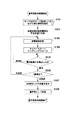
[基準値取得処理のフローチャー]
図5のフローチャートは、色ずれ補正制御における基準値取得処理を示すフローチャートである。まず、図5のフローチャートは、センサ40のマーク(図6)の検出による色ずれ補正制御(以下通常色ずれ補正制御と称する)が行われることに引続き実行される。また、感光体ドラム22および現像スリーブ24などの部品が交換がされ通常色ずれ補正制御が実行されるとき、特定のタイミングの通常色ずれ補正制御のみに対応させて図5のフローチャートを実行しても良い。また、図5のフローチャートは各色について独立して行われるものとする。
[Flower of reference value acquisition processing]
The flowchart of FIG. 5 is a flowchart showing a reference value acquisition process in the color misregistration correction control. First, the flowchart of FIG. 5 is executed following execution of color misregistration correction control (hereinafter referred to as normal color misregistration correction control) based on detection of the mark (FIG. 6) of the
ステップS501により制御部54は、画像形成部により中間転写ベルト30上に色ずれ検出用のマークを形成させる。色ずれ検出用マークの形成様子を図6に示す。
In step S501, the
400と401は用紙搬送方向(副走査方向)の色ずれ量を検出する為のパターンを示す。また402と403は用紙搬送方向と直交する主走査方向の色ずれ量を検出する為のパターンを示し、この例では45度傾いている。また、tsf1〜4、tmf1〜4、tsr1〜4、tmr1〜4、は各パターンの検出タイミングを、矢印は中間搬送ベルト34の移動方向を示す。 Reference numerals 400 and 401 denote patterns for detecting a color misregistration amount in the paper conveyance direction (sub-scanning direction). Reference numerals 402 and 403 denote patterns for detecting the amount of color misregistration in the main scanning direction orthogonal to the paper transport direction, and in this example, the pattern is inclined 45 degrees. Further, tsf1 to 4, tmf1 to 4, tsr1 to 4, and tmr1 to 4 indicate the detection timing of each pattern, and the arrows indicate the moving direction of the intermediate conveyance belt 34.
中間搬送ベルト34の移動速度をvmm/s、Yを基準色とし、用紙搬送方向用パターンの各色とYパターン間の理論距離をdsYmm、dsMmm、dsCmmとする。Yを基準色とし、搬送方向に関して、各色の色ずれ量δesは、次の[式1]〜[式3]のようになる。
δesM=v*{(tsf2−tsf1)+(tsr2−tsr1)}/2−dsY…式1
δesC=v*{(tsf3−tsf1)+(tsr3−tsr1)}/2−dsM…式2
δesBk=v*{(tsf4−tsf1)+(tsr4−tsr1)}/2−dsC…式3
主走査方向に関して、左右各々の各色の位置ずれ量δemf、δemrは、
dmfY=v×(tmf1−tsf1) … 式4
dmfM=v×(tmf2−tsf2) … 式5
dmfC=v×(tmf3−tsf3) … 式6
dmfBk=v×(tmf4−tsf4) … 式7
と、
dmrY=v×(tmr1−tsr1) … 式8
dmrM=v×(tmr2−tsr2) … 式9
dmrC=v×(tmr3−tsr3) … 式10
dmrBk=v×(tmr4−tsr4) … 式11
から、
δemfM=dmfM−dmfY … 式12
δemfC=dmfC−dmfY … 式13
δemfBk=dmfBk−dmfY … 式14
と、
δemrM=dmrM−dmrY … 式15
δemrC=dmrC−dmrY … 式16
δemrBk=dmrBk−dmrY … 式17
となり、計算結果の正負からずれ方向が判断でき、δemfから書き出し位置を、δemr−δemfから主走査幅(主走査倍率)を補正する。尚、主走査幅(主走査倍率)に誤差がある場合は、書き出し位置はδemfのみでなく、主走査幅補正に伴い変化した画像周波数(画像クロック)の変化量を加味して算出する。
The moving speed of the intermediate conveyance belt 34 is vmm / s, Y is a reference color, and the theoretical distance between each color of the paper conveyance direction pattern and the Y pattern is dsYmm, dsMmm, and dsCmm. With Y as a reference color, the color misregistration amount δes of each color in the transport direction is expressed by the following [Expression 1] to [Expression 3].
δesM = v * {(tsf2−tsf1) + (tsr2−tsr1)} / 2−dsY.
δesC = v * {(tsf3−tsf1) + (tsr3−tsr1)} / 2−dsM.
δesBk = v * {(tsf4−tsf1) + (tsr4−tsr1)} / 2−dsC Equation 3
With respect to the main scanning direction, the positional deviation amounts δemf and δemr for each of the left and right colors are
dmfY = v × (tmf1−tsf1) Equation 4
dmfM = v × (tmf2−tsf2) Equation 5
dmfC = v × (tmf3-tsf3) Equation 6
dmfBk = v × (tmf4-tsf4) Equation 7
When,
dmrY = v × (tmr1−tsr1) Equation 8
dmrM = v × (tmr2−tsr2) Equation 9
dmrC = v × (tmr3-tsr3)
dmrBk = v × (tmr4-tsr4)
From
δemfM = dmfM−dmfY
δemfC = dmfC−dmfY
δemfBk = dmfBk−dmfY
When,
δemrM = dmrM−dmrY
δemrC = dmrC−dmrY
δemrBk = dmrBk−dmrY
Thus, the deviation direction can be determined from the sign of the calculation result, the writing position is corrected from δemf, and the main scanning width (main scanning magnification) is corrected from δemr−δemf. When there is an error in the main scanning width (main scanning magnification), the writing position is calculated not only by δemf but also by taking into account the amount of change in the image frequency (image clock) that has changed with the main scanning width correction.
そして、演算された色ずれ量を解消するように、制御部54は、画像形成条件としてのスキャナユニット20aによるレーザ光の出射タイミングを変更する。例えば、副走査方向の色ずれ量が−4ライン分の量であれば、制御部54は、ビデオコントローラ200に、レーザ光の出射タイミングを+4ライン分早めるよう指示する。
Then, the
図5のフローチャートの説明に戻る。ステップS502で、制御部54は、感光体ドラム22a〜22dの回転速度に変動がある場合の影響を抑制すべく、感光ドラム22a〜22d間の回転位相関係を所定の状態に合わせる。具体的には、制御部54の制御のもと、基準色の位相に対して、他の色の感光ドラムの位相を調整する。また、感光ドラムの軸に感光ドラム駆動ギアが設けられているような場合は、実質的には各感光ドラムの駆動ギアの位相関係を調整する。これにより、各ドラムに現像されたトナー像が中間転写ベルト30に転写されるときのドラムの回転速度が略同じ、或いは同様の速度変動傾向になる。具体的には、制御部54は不図示の感光ドラムを駆動するモータに対して、感光ドラム22a〜22d間の回転位相関係を所定の状態に合わせるよう速度制御指示を行う。尚、感光ドラムの回転速度変動が無視できる程度の場合は、ステップS502の処理を省略しても良い。
Returning to the flowchart of FIG. In step S502, the
ステップS503で、制御部54は、各感光ドラムにおいて所定の回転位相にて、レーザスキャナユニット20a〜20dに、レーザ光を発光させ、感光ドラム上に静電潜像を形成する。
In step S503, the
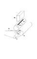
図7は、イエローの感光体ドラム22aを用いて、静電潜像が感光ドラム上に形成された様子を示す図である。図中で80が形成された静電潜像を示している。静電潜像80は、走査方向の画像領域幅において最大限幅広く描かれ、搬送方向に5ライン程度の幅を持つものである。尚、主走査方向の幅については、良好な検出結果を得る意味で、最大幅の半分以上の幅で形成するようにすることが望ましい。この時、例えば、現像スリーブ24aを感光体ドラム22aから離した状態とすることで、静電潜像80は、トナーが付着されることなく1次転写ローラ26aの位置まで搬送される。また、現像バイアス高圧電源回路44a〜44dから出力される電圧をゼロにしたり、通常とは逆極性のバイアスを印加することで、トナーを付着させないようにしても良い。
FIG. 7 is a diagram illustrating a state where an electrostatic latent image is formed on the photosensitive drum using the yellow
また、制御部54は、ステップS503の処理と同時或いは略同時にYMCKの夫々に対応して用意されたタイマーをスタートさせる(ステップS504)。また、センサ40の検出値のサンプリングを開始する。このとき、サンプリング周波数は、例えば10kHzである。
Further, the
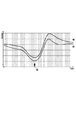
そして、制御部54は、ステップS505で、ステップS503のサンプリングにより取得されたデータを基に、静電潜像80の検出によって1次転写電流の検出値が極小になる時間(タイマー値)を測定する。図8に検出結果の一例を示す。
In step S505, the
図8は、静電潜像80がプロセス手段としての1次転写ローラ26aに到達した時の、電流検出回路46aからの、感光体の表面電位に係る出力値を測定したものである。後述の図9にて詳しく説明するが、この図8の情報は、感光ドラムの表面電位に応じたものであり、その意味で感光ドラムの表面電位情報と称することができる。縦軸は検出した電流を、横軸は時間を示し、横軸の1目盛は、レーザスキャナが1ラインを走査する時間を示したものである。電流波形90、91は、夫々別のタイミングで測定したものである。電流波形90、91の何れにおいても、静電潜像80が1次転写ローラ26aに到達したことで、時刻92において極小となり、その後復帰してゆく特性を示している。
FIG. 8 shows the measurement of the output value related to the surface potential of the photoconductor from the
ここで、検出される電流値が減少する理由について説明する。図9は、静電潜像上にトナー付着が有る場合と無い場合とにおける、感光体ドラム22aの表面電位を示す模式図である。横軸は感光体ドラム22aの搬送方向の表面位置を示し、領域93が静電潜像80が形成された位置を示している。また縦軸は電位を示し、感光体ドラム22aの暗電位をVD、明電位をVL、1次転写ローラ26aの転写バイアス電位をVTとして記載した。
Here, the reason why the detected current value decreases will be described. FIG. 9 is a schematic diagram showing the surface potential of the
静電潜像80の領域93では、1次転写ローラ26aと感光体ドラム22aとの電位差96が、それ以外の領域における電位差95と比べ小さくなる。このため、静電潜像80が1次転写ローラ26aに到達すると、1次転写ローラ26aに流れる電流値は減少する。これが上で説明した図8の極小値が検出される理由である。このように検出される電流値は感光ドラムの表面電位を反映したものとなっている。
In the
図5のフローチャートの説明に戻る。最後に、制御部54は、ステップS506において、ステップS505で測定した時間(タイマー値)を、基準値としてEEPROM324に記憶する。ステップS506で求められるタイマー値はステップS503でのレーザスキャナユニット20a〜20dによる静電潜像形成のタイミングが基(基準)になっている。静電潜像形成のタイミングが基になっているとは、静電潜像形成のタイミングそのものでなくとも、例えば静電潜像形成の1秒前等、静電潜像形成のタイミングに関連したタイミングでもよいということである。尚、EEPROM324は、例えばバックアップ電池付きのRAM等でも良い。また、記憶される時間の情報は時間を特定できるものであれば良く、例えば秒数そのものの情報でも良いし、クロックカウント値でも良い。
Returning to the flowchart of FIG. Finally, in step S506, the
[ステップS505の詳細説明]
ここで、検出波形90、91が極小となる時間を測定することが好適な理由を説明する。これは、検出波形90と91の様に測定した電流の絶対値が異なった場合においても、静電潜像80が1次転写ローラ26aに到達するタイミングを正確に測定することが出来る為である。また、検出用パターンを図7の静電潜像80の様な形状にした理由は、主走査方向に広いパターンとすることで電流値の変化を大きくする為である。また、感光ドラムの搬送方向(副走査方向)に数ライン分の幅とすることで電流値の大きな変化を保ちつつ極小となる点が鋭く現れるようにしている。従って静電潜像80の最適な形は装置の構成によって異なり、本実施例で用いた搬送方向に5ラインの幅を持つ形などに限定するものでは無い。
[Detailed Description of Step S505]
Here, the reason why it is preferable to measure the time when the
また、図8に示した検出結果が好適ではあるが、例えば静電潜像80の搬送方向に5ラインよりも多い20ラインとすることで、検出結果にフラットとなる領域を作り、その中点を検出するようにしても良い。即ち、後述の図10のフローチャートを実行したときに、検出結果から、図5のフローチャートで検出した特定の条件(特徴的位置)と合致する位置を検出できればよい。そのような態様であれば、上述した極小位置に限らず様々な検出結果の特徴的位置を図5、図10のステップS505の判断対象に適用することができる。また、後述の図12、13についても同様である。
Further, although the detection result shown in FIG. 8 is suitable, for example, by setting 20 lines more than 5 lines in the transport direction of the electrostatic
尚、以上の説明では、図5のフローチャートによる色ずれ検出時に、現像スリーブ24aを感光体ドラム22aから離し、静電潜像80にトナーを載せずに検出する構成を説明した。しかしこれに限定去れるものでは無い。トナーを載せた状態でも色ずれを検出可能である。
In the above description, the configuration in which the developing
図9(b)は、静電潜像80にトナーを載せた時の、感光体ドラム22aと1次転写ローラ26aの電位差を示した模式図である。図9(a)と同じ要素には同一の符号を付し、その説明を省略する。静電潜像80にトナーを載せた場合、静電潜像80の領域93では、1次転写ローラ26aと感光体ドラム22aとの電位差97が、トナーを載せなかった時の電位差96と比べ大きい。また、それ以外の領域における電位差95との差が小さくなる。しかし変化を十分に検出可能である。ここで、色ずれ検出後に感光ドラム22や中間転写ベルト30上のトナーを清掃する必要が生じてしまうが、濃度が濃くなければ、簡易なクリーニングでよく、実質問題は無い。少なくとも中間転写ベルト30等に100%濃度の色ずれ補正における検出用トナー像を転写し、それをクリーニングする場合と比べれば短い時間でクリーニングを行える。
FIG. 9B is a schematic diagram showing a potential difference between the
[色ずれ補正制御のフローチャート]
次に、図10のフローチャートを用いて、本実施例における色ずれ補正制御について説明を行う。尚、図10のフローチャートは各色について独立して行われるものとする。
[Flow chart of color misregistration correction control]
Next, color misregistration correction control in the present embodiment will be described using the flowchart of FIG. In addition, the flowchart of FIG. 10 shall be performed independently about each color.
まずステップS502〜ステップS505については、図5のフローチャートと同様の処理を行う。感光体ドラム22aの軸に偏りが有る場合、上で説明した静電潜像80が1次転写ローラ26aに到達するまでの時間も変化してしまう。この変化を検出する為に、図10のステップS503でも、図5のステップS503と同じ位置で静電潜像80を形成する。
First, in steps S502 to S505, processing similar to that in the flowchart of FIG. 5 is performed. When the axis of the
そして、制御部54は、ステップS1001で電流極小を検出した時のタイマー値を、図5のフローチャートのステップS506で保存した基準値と比較する。ステップS1002でタイマー値が基準値より大きい場合は、画像形成条件としてのレーザビーム発光タイミングに関して、印刷時にレーザビーム発光タイミングを早めるよう補正する。他方、ステップS1003で、検出されたタイマー値が基準値より小さい場合は、印刷時にレーザビームを発光するタイミングを遅くする。このステップS1002、S1003の画像形成条件補正処理により色ずれを補正実現する。
Then, the
尚、図10のフローチャートのステップS1001で、制御部54は電流極小を検出した時のタイマー値と、ステップS506で保存した基準値と比較するよう説明したが、それに限定されない。あるタイミングにおける色ずれ状態を維持するという観点では、任意の色ずれ発生状態においてステップS502〜ステップS506を実行し、記憶された基準値をステップS1001の比較対象としても良い。これは後述の図12、13においても同様である。
In addition, although it demonstrated that the
以上のように、制御部54により図10のフローチャートが実行されることで、感光ドラムから像担持体(ベルト)に、色ずれ補正制御における検出用トナー像(100%濃度)を転写しなくとも、色ずれ補正制御を実現できる。即ち、画像形成装置のユーザビリティーを持たせつつ、色ずれ補正制御を行える。
As described above, the flowchart of FIG. 10 is executed by the
一方、装置内温度の変化量に対する色ずれ量の変化傾向を予め測定しておき、測定した装置内温度を基に色ずれ量を予測演算し、色ずれ補正制御を行うことも、従来から知られている。この色ずれ補正制御の方法によれば、検出用のトナー像を像担持体上に形成する必要がないメリットがある。しかし、色ずれ量を予測演算する色ずれ補正制御方法では、トナー消費を抑えることができるものの、実際に発生している色ずれ量が必ずしも予測演算結果と一致しているとは限らず、精度の面で難点があった。これに対して、図10のフローチャートによれば、トナー消費を抑えることを可能にしつつも、一定の色ずれ補正制御の精度を確保することができる。 On the other hand, it has also been conventionally known that a color shift amount change tendency with respect to a change amount in the apparatus temperature is measured in advance, the color shift amount is predicted based on the measured apparatus temperature, and color shift correction control is performed. It has been. This color misregistration correction control method has an advantage that it is not necessary to form a detection toner image on the image carrier. However, in the color misregistration correction control method that predicts and calculates the color misregistration amount, although toner consumption can be suppressed, the actual color misregistration amount does not necessarily match the prediction calculation result. There was a difficulty in terms of. On the other hand, according to the flowchart of FIG. 10, it is possible to ensure a certain accuracy of color misregistration correction control while making it possible to suppress toner consumption.
図11は、実施例1とは別の形態の画像形成装置の構成図である。実施例1と同じ構成には同一の番号を付し、その説明を省略する。図1で説明した画像形成装置と異なる点は、図11の構成では、現像スリーブ24a〜24dが、感光体ドラム22a〜22dから常に離間している点である。印刷時は、現像高圧電源回路44a〜44dが現像スリーブ24a〜24dに交流のバイアス電圧を印加することで、感光体ドラム22a〜22dと現像スリーブ24a〜24dとの間にトナーを往復運動させ、静電潜像にトナーを付着させる。この構成では、現像高圧電源回路44a〜44dを停止するだけで静電潜像80にトナーが感光ドラムに付着しなくなる。
FIG. 11 is a configuration diagram of an image forming apparatus in a form different from that of the first embodiment. The same components as those in the first embodiment are denoted by the same reference numerals, and the description thereof is omitted. A difference from the image forming apparatus described in FIG. 1 is that the developing
また、図11の構成では、感光体ドラム22a〜22dを独立した駆動源28a〜28dによって駆動し、それぞれ回転速度を設定することが出来るよう構成されている。そこで、感光体ドラム22a〜22dの回転速度を夫々変化させることによって、レーザ光21a〜21dの照射から、静電潜像80が1次転写ローラ26a〜26dに到達するまでの時間を一定に調整し、検出した搬送方向の色ずれ量を打ち消すよう構成されている。
In the configuration of FIG. 11, the
ここで、本実施例では、各感光体ドラム22a〜22dの位相を検出していない構成を想定している。一方、感光体ドラム22aの軸に無視できない偏りが有る場合、前述した静電潜像80が1次転写ローラ26aに到達する時間の測定結果も変化してしまう。そこで本実施例では、複数回の測定を行い、その平均を基に色ずれを補整する。尚、以下に示す各フローチャートが図1で説明した画像形成装置を利用した場合にも適用可能であることはいうまでもない。
Here, in this embodiment, it is assumed that the phase of each of the
図12のフローチャートは、実施例2における基準値取得処理を示すフローチャートである。尚、図12のフローチャートは各色について独立して行われるものとする。 The flowchart in FIG. 12 is a flowchart illustrating the reference value acquisition process in the second embodiment. Note that the flowchart of FIG. 12 is performed independently for each color.
まずステップS1201乃至S1205の処理は、図5のステップS501乃至S505の処理と同様であり、ここでの詳しい説明は省略する。 First, the processing of steps S1201 to S1205 is the same as the processing of steps S501 to S505 in FIG. 5, and detailed description thereof is omitted here.
そして、ステップS1206で、感光体ドラム22a〜22dの軸が偏っていた時の影響を打ち消すため、極小を検出するタイマー値測定をn回繰り返すまで、制御部54は、ステップS1203乃至S1205の処理を繰り返し実行するよう制御を行う。尚、nは2以上の整数値とする。
In step S1206, the
そして、ステップS1206で、n回の測定が終了したと制御部54が判断すると、ステップS1207で、制御部54は、n回の測定で得られたタイマー値(時間)の平均値を算出する。そして、ステップS1208で、制御部54は、平均値のデータ(代表時間)を代表値(基準値)としてEEPROM324に記憶する。尚、平均の演算方法については、単純平均や重み付け平均など様々な演算方法が想定される。このように、ステップS1208では、複数の取得されたデータに基き基準値を算出するので、少なくとも単一のデータに基き基準値を算出するよりは精度を向上させることができる。
In step S1206, when the
[色ずれ補正制御のフローチャート]
次に図13のフローチャートの説明を行う。図12と同じ処理には同じステップ番号を付してある。尚、図13のフローチャートは各色について独立して行われるものとする。
[Flow chart of color misregistration correction control]
Next, the flowchart of FIG. 13 will be described. The same steps as those in FIG. 12 are given the same step numbers. Note that the flowchart of FIG. 13 is performed independently for each color.
まず、図13のステップS1202乃至S1205の処理は、今述べたように図12の対応する処理と同様である。感光体ドラム22a〜22dの回転軸が偏っていた場合の影響を抑制すべく、極小を検出するタイマー値測定をn回繰り返すまで、制御部54は、ステップS1203乃至S1205の処理を繰り返し実行する。
First, the processing in steps S1202 to S1205 in FIG. 13 is the same as the corresponding processing in FIG. 12 as described above. In order to suppress the influence when the rotating shafts of the
そして、ステップS1301でn回の測定が終了したと制御部54が判断すると、制御部54は、ステップS1302で、n回測定した各タイマー値の平均を算出する。ステップS1303で、制御部54は、記憶部(EEPROM324)より図12のステップS1208で記憶保存した基準値を読み出す。そして制御部54は、算出した平均値と、読み出した代表値(基準値)とを比較する。
Then, when the
平均値が基準値より大きい場合、制御部54は、ステップS1304で、印刷時にその時間分だけ、画像形成条件としての感光体ドラムの回転速度を早める。一方、平均値が基準値より小さい場合、制御部54は、印刷時にその時間分だけ、画像形成条件としての感光体ドラムの回転速度を遅くすることによって、色ずれを補正する。勿論、画像形成条件の補正として、図10のフローチャートで説明したステップS1002やステップS1003の処理を行っても良い。
If the average value is larger than the reference value, the
[感光ドラム位相の分散]
図12、図13のステップS1203の静電潜像走査の処理を、各ページ間における非画像領域で実行する場合、図12のステップS1206、図13のステップS1301における判断回数nは、画像形成装置の各部材の寸法で決まる。具体的には、用紙サイズと、感光体ドラムのドラム周長と、画像の移動方向(感光ドラムの回転方向)における非画像領域の幅とから決まる。
[Photosensitive drum phase dispersion]
When the electrostatic latent image scanning process in step S1203 in FIGS. 12 and 13 is executed in a non-image area between pages, the number of determinations n in step S1206 in FIG. 12 and step S1301 in FIG. It is determined by the dimensions of each member. Specifically, it is determined from the paper size, the drum circumference of the photosensitive drum, and the width of the non-image area in the image moving direction (rotating direction of the photosensitive drum).
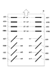
例えば、用紙サイズがA4(297mm)で、非画像領域の画像移動方向幅が64.0mmで、ドラム周長が75.4mmの場合に、各非画像領域の中心における感光ドラムの位相がどのように変化していくかを図14(a)のグラフに示す。また、用紙サイズ、非画像領域幅、ドラム周長が異なる数値の場合の一例を図14(b)に示す。この図14で説明することは各色について同様にいえることである。 For example, when the paper size is A4 (297 mm), the image moving direction width of the non-image area is 64.0 mm, and the drum circumference is 75.4 mm, what is the phase of the photosensitive drum at the center of each non-image area? The graph of FIG. FIG. 14B shows an example in which the paper size, the non-image area width, and the drum circumference are different values. What is described in FIG. 14 is the same for each color.
これら図14のグラフは、各非画像領域の中央で、図12、13のステップS1203を実行したときに、静電潜像がどの感光ドラム位相に対応して形成されるかを示した図である。図14(a)、(b)の何れにおいても、複数回の各非画像領域で図12、13のステップS1203における静電潜像を形成すれば、感光ドラムの位相条件が平均化されることが示されている。 These graphs of FIG. 14 are diagrams showing to which photosensitive drum phase an electrostatic latent image is formed when step S1203 of FIGS. 12 and 13 is executed at the center of each non-image area. is there. 14A and 14B, if the electrostatic latent image in step S1203 in FIGS. 12 and 13 is formed in each non-image area a plurality of times, the phase condition of the photosensitive drum is averaged. It is shown.
ここで、図15は、用紙サイズ、非画像領域幅の夫々がどのような事項を指すのかを説明する為の図である。図15は、中間転写ベルト上に仮にトナー像が転写されたときの1次転写位置と、そのトナー像に対応する露光を行ったときの感光ドラムの位相と、の対応関係を示している。また非画像領域とは、画像形成において静電潜像を形成し得る領域(有効画像領域)以外の感光ドラム上の領域や、ページ間領域(紙間領域)など、感光ドラム上における領域としても定義できる。また、レーザスキャナ20が各ページの画像形成の為のレーザ照射を行わない期間(時間)としても定義できる。 Here, FIG. 15 is a diagram for explaining what the paper size and the non-image area width indicate. FIG. 15 shows the correspondence between the primary transfer position when the toner image is transferred onto the intermediate transfer belt and the phase of the photosensitive drum when exposure corresponding to the toner image is performed. The non-image area is an area on the photosensitive drum, such as an area on the photosensitive drum other than an area where an electrostatic latent image can be formed in image formation (effective image area), or an inter-page area (inter-paper area). Can be defined. It can also be defined as a period (time) in which the laser scanner 20 does not perform laser irradiation for image formation on each page.
図15において、非画像領域1505(1509)の開始位置1502(1506)、中心1504(1508)及び終了位置1503(1507)の夫々の位相は、1501の位置に対応する感光ドラムの位相と、用紙サイズにより決まる。尚、夫々の感光ドラムの位相は、上で説明したように、仮にトナー像が1次転写されるとして、そのトナー像を露光したときの感光ドラムの位相である。
In FIG. 15, the phases of the start position 1502 (1506), the center 1504 (1508) and the end position 1503 (1507) of the non-image area 1505 (1509) are the same as the phase of the photosensitive drum corresponding to the
また図15では、1501の位相がゼロで示されているが、他の任意の値でも問題ない。即ち、1501の位相がゼロでなくとも、図14で示される位相の変化が、幾つ目(何枚目)の非画像領域で出てくるかに関して、出現タイミングがシフトするのみである。即ち、図12、13のステップS503の静電潜像形成時の感光ドラム位相が分散されるという意味では大差ない。 In FIG. 15, the phase of 1501 is shown as zero, but any other value is acceptable. That is, even if the phase of 1501 is not zero, the appearance timing is only shifted with respect to how many (how many) non-image areas the phase change shown in FIG. 14 appears. That is, there is no significant difference in the sense that the photosensitive drum phase is dispersed when forming the electrostatic latent image in step S503 in FIGS.
以上のように、制御部54により図12、図13のフローチャートが実行されることで、実施例1と同様の効果に加え、平均値を用いたより精度の高い色ずれ補正制御を実現できる。また、静電潜像を形成するときの感光ドラムの位相に依存しない色ずれ補正制御を行うことができ、色ずれ補正制御の開始タイミングについてより自由度を持たせることができる。
As described above, by executing the flowcharts of FIGS. 12 and 13 by the
上記実施例では、出力端子53の電圧に従い、1次転写ローラ26a及び感光体ドラム22a及びグランドを経由して流れる電流値を、感光ドラムの表面電位に係る出力値として検出するよう説明した。しかしこれに限定されない。感光体ドラム22a〜22dの周囲には、1次転写ローラ26a〜26dの他に、帯電ローラ23a〜23dや現像スリーブ24a〜24dなどの設けられている。これら帯電ローラ23a〜23dや現像スリープ(現像ローラ)24a〜24dに、上記実施例1或いは2を適用することもできる。即ち、上の説明の如く感光体上に形成された静電潜像80が、プロセス手段としての帯電ローラ23a〜23dや現像スリープ(現像ローラ)24a〜24dに到達したときの感光体の表面電位に係る出力値を測定してもよい。
In the above-described embodiment, the current value flowing through the
以下、一例として、例えば帯電ローラ23及び感光ドラム22を経由して流れる電流値を、感光ドラムの表面電位に係る出力値として検出する場合について説明を行う。この場合、帯電ローラ毎に接続された帯電高圧電源回路43a〜43d(不図示)を設け、各帯電高圧電源回路について図4で示した高圧電源回路と同様の回路を設け、その出力端子53を対応する帯電ローラ43に接続すれば良い。この場合の帯電高圧電源回路を図16に示す。図4との違いは、1つに出力端子53が帯電ローラ23aに接続されている点がある。また、ダイオード64、65に対して、カソード・アノードの向きが逆のダイオード1601、1602が高圧電源回路を構成している点も異なる。これは、本実施例の画像形成装置においては、1次転写バイアス電圧が正電圧であるのに対して、帯電バイアス電圧が負電圧であるからである。尚、他の色の帯電高圧電源回路43〜43dについては、図16に示される回路構成と同じであるので、1次転写高圧電源回路のときの同様に詳しい説明を省略する。
Hereinafter, as an example, a case where a current value flowing through the charging roller 23 and the photosensitive drum 22 is detected as an output value related to the surface potential of the photosensitive drum will be described. In this case, charging high-voltage
そして、図5及び図10、図12及び図13のフローチャートを、1次転写高圧電源回路46a〜46dにかわって、帯電高圧電源回路43a〜43d(不図示)を動作させ実行すれば良い。尚、このとき、検出電流値56に対して予め設定された電流目標値は、帯電ローラ23の特性、及び他部材との関係等を考慮して適宜設定されているものとする。
The flowcharts of FIGS. 5, 10, 12, and 13 may be executed by operating the charging high-voltage
また、現像高圧電源回路44a〜44dを動作さえ、図5及び図10、図12及び図13のフローチャートを実行する場合も、帯電高圧電源回路43a〜43dの場合と同様なので、詳しい説明を省略する。
Further, even when the development high-voltage
[変形例]
尚、上の説明においては、中間転写ベルト30を有する画像形成装置について述べたが、各感光ドラム22に現像されたトナー像を転写材(記録材)に直接転写する方式を採用した画像形成装置にも転用できる。
[Modification]
In the above description, the image forming apparatus having the
また、一次手転写手段として1次転写ローラ26aを例に説明を行ったが、例えば、転写ブレードによる接触式の1次転写手段を適用しても良い。また、特開2007−156455号公報に示されるような面押圧により1次転写ニップ部を形成するような1次転写手段を適用しても良い。
Further, the
また上の説明では、感光ドラムの表面電位を反映した表面電位情報として、電流検出回路46aにより電流情報を検出するよう説明した。これは制御部54が画像形成時の1次転写中に定電圧制御を行うからである。他方、別の1次転写方式として、定電流印加方式にて1次転写手段に対して転写電圧を印加することも知られている。即ち、画像形成時の1次転写方式として定電流制御を採用することも想定される。そして、この場合には、感光ドラムの表面電位を反映した表面電位情報として電圧の変動が検出される。そして図8の場合と同様に電圧変化の特徴的形状が検出されるまでの時間について、上述で説明したフローチャートと同様の処理を行えば良い。またこのことは、実施例3で説明した帯電高圧電源回路43a〜43d、現像高圧電源回路44a〜44dについても、同様のことがいえる。
In the above description, the current information is detected by the
20a〜20d レーザスキャナ
22a〜22d 感光体ドラム
24a〜24d 現像スリーブ
26a〜26d 1次転写ローラ
30 中間転写ベルト
46a〜46d 1次転写高圧電源回路
47a〜47d 電流検出回路
80 静電潜像
20a to
Claims (13)
前記プロセス手段に電力を供給する電源手段と、
前記光照射手段が、前記感光体に光を照射し検出用の静電潜像を形成するタイミングを基に、前記検出用の静電潜像が前記プロセス手段に対向する位置を通過する際の前記プロセス手段を介して生じる前記電源手段の出力が検出されるまでの時間を検出する検出手段と、
前記検出手段からの検出結果に基づき、画像形成時の静電潜像を形成する位置を補正する制御手段と、を備えることを特徴とする画像形成装置。 A rotationally driven photoreceptor, process means disposed around the photoreceptor and acting on the photoreceptor, and light irradiation means for forming an electrostatic latent image on the photoreceptor by irradiating light. In the image forming apparatus capable of forming a detection electrostatic latent image on the photoconductor,
Power supply means for supplying power to the process means;
Based on the timing at which the light irradiating means irradiates the photosensitive member with light to form a detection electrostatic latent image, the detection electrostatic latent image passes through a position facing the process means. Detection means for detecting time until the output of the power supply means generated via the process means is detected;
An image forming apparatus comprising: a control unit that corrects a position where an electrostatic latent image is formed at the time of image formation based on a detection result from the detection unit.
前記制御手段は、前記検出手段の検出対象となる何れかのプロセス手段よりも前記静電潜像の移動方向において上流側に配置された他のプロセス手段を、前記検出用の静電潜像が前記他のプロセス手段に対向する位置を通過する際に、トナー像の形成位置から離隔させる、又は通常の画像形成時よりも前記感光体への作用が少なくとも小さくなる設定にすることを特徴とする請求項1に記載の画像形成装置。 The process means is composed of a plurality of types of process means,
The control means may be arranged such that the detection electrostatic latent image has another process means disposed upstream in the movement direction of the electrostatic latent image with respect to any process means to be detected by the detection means. When passing through a position facing the other process means, the toner image is separated from the formation position, or the action on the photoconductor is set to be at least smaller than that during normal image formation. The image forming apparatus according to claim 1 .
前記制御手段は、画像形成時の静電潜像を形成する位置を補正することによって、前記複数の感光体の間における色ずれを補正することを特徴とする請求項1乃至11の何れか1項に記載の画像形成装置。 Having a plurality of photoconductors,
Wherein, by correcting the position for forming an electrostatic latent image at the time of image formation, any one of claims 1 to 11, characterized in that to correct the color shift between the plurality of photosensitive member 1 The image forming apparatus described in the item.
前記検出手段は、前記時間を各色について検出し、The detection means detects the time for each color,
前記制御手段は、前記位置を各色について補正することを特徴とする請求項1に記載の画像形成装置。The image forming apparatus according to claim 1, wherein the control unit corrects the position for each color.
Priority Applications (1)
| Application Number | Priority Date | Filing Date | Title |
|---|---|---|---|
| JP2011164992A JP5653314B2 (en) | 2011-07-28 | 2011-07-28 | Color image forming apparatus |
Applications Claiming Priority (1)
| Application Number | Priority Date | Filing Date | Title |
|---|---|---|---|
| JP2011164992A JP5653314B2 (en) | 2011-07-28 | 2011-07-28 | Color image forming apparatus |
Related Parent Applications (1)
| Application Number | Title | Priority Date | Filing Date |
|---|---|---|---|
| JP2010149479 Division | 2010-06-30 | 2010-06-30 |
Publications (3)
| Publication Number | Publication Date |
|---|---|
| JP2012014176A JP2012014176A (en) | 2012-01-19 |
| JP2012014176A5 JP2012014176A5 (en) | 2013-08-15 |
| JP5653314B2 true JP5653314B2 (en) | 2015-01-14 |
Family
ID=45600588
Family Applications (1)
| Application Number | Title | Priority Date | Filing Date |
|---|---|---|---|
| JP2011164992A Expired - Fee Related JP5653314B2 (en) | 2011-07-28 | 2011-07-28 | Color image forming apparatus |
Country Status (1)
| Country | Link |
|---|---|
| JP (1) | JP5653314B2 (en) |
Families Citing this family (12)
| Publication number | Priority date | Publication date | Assignee | Title |
|---|---|---|---|---|
| JP5653283B2 (en) | 2010-06-30 | 2015-01-14 | キヤノン株式会社 | Color image forming apparatus and image forming apparatus |
| JP2013156547A (en) * | 2012-01-31 | 2013-08-15 | Canon Inc | Image forming apparatus |
| JP2013156548A (en) * | 2012-01-31 | 2013-08-15 | Canon Inc | Image forming apparatus |
| JP5967957B2 (en) | 2012-01-31 | 2016-08-10 | キヤノン株式会社 | Image forming apparatus |
| JP6039904B2 (en) * | 2012-01-31 | 2016-12-07 | キヤノン株式会社 | Image forming apparatus |
| JP2013156546A (en) * | 2012-01-31 | 2013-08-15 | Canon Inc | Image forming apparatus |
| JP5904844B2 (en) * | 2012-04-04 | 2016-04-20 | キヤノン株式会社 | Image forming apparatus |
| JP5939934B2 (en) * | 2012-08-13 | 2016-06-22 | キヤノン株式会社 | Speed ratio fluctuation calculating device and image forming apparatus |
| JP6204705B2 (en) * | 2013-06-06 | 2017-09-27 | キヤノン株式会社 | Image forming apparatus |
| JP6204706B2 (en) * | 2013-06-06 | 2017-09-27 | キヤノン株式会社 | Image forming apparatus |
| JP6204704B2 (en) * | 2013-06-06 | 2017-09-27 | キヤノン株式会社 | Image forming apparatus |
| CN111222358B (en) * | 2018-11-23 | 2024-02-13 | 杭州海康威视数字技术股份有限公司 | Face static detection method and system |
Family Cites Families (8)
| Publication number | Priority date | Publication date | Assignee | Title |
|---|---|---|---|---|
| JPH05323744A (en) * | 1992-05-19 | 1993-12-07 | Minolta Camera Co Ltd | Image forming device |
| JPH1039571A (en) * | 1996-07-19 | 1998-02-13 | Fuji Xerox Co Ltd | Multicolor image forming device and color slippage adjustment method thereof |
| JP3612695B2 (en) * | 1996-10-23 | 2005-01-19 | 富士ゼロックス株式会社 | Multicolor image forming apparatus and color misregistration adjusting method thereof |
| JP2005017768A (en) * | 2003-06-26 | 2005-01-20 | Ricoh Co Ltd | Multi-color image forming apparatus |
| JP4438484B2 (en) * | 2004-04-05 | 2010-03-24 | 富士ゼロックス株式会社 | Image forming apparatus |
| JP4865283B2 (en) * | 2005-09-13 | 2012-02-01 | 株式会社リコー | Image forming apparatus and phase alignment method for a plurality of image carriers |
| JP5364985B2 (en) * | 2007-09-04 | 2013-12-11 | コニカミノルタ株式会社 | Image forming apparatus |
| JP5025526B2 (en) * | 2008-02-29 | 2012-09-12 | ブラザー工業株式会社 | Image forming apparatus |
-
2011
- 2011-07-28 JP JP2011164992A patent/JP5653314B2/en not_active Expired - Fee Related
Also Published As
| Publication number | Publication date |
|---|---|
| JP2012014176A (en) | 2012-01-19 |
Similar Documents
| Publication | Publication Date | Title |
|---|---|---|
| JP5653314B2 (en) | Color image forming apparatus | |
| US8891984B2 (en) | Color image forming apparatus | |
| JP6061461B2 (en) | Color image forming apparatus | |
| JP6261711B2 (en) | Color image forming apparatus | |
| US9042754B2 (en) | Image forming apparatus having latent image timing | |
| JP5863314B2 (en) | Color image forming apparatus | |
| JP6204706B2 (en) | Image forming apparatus | |
| JP2014044307A (en) | Image forming apparatus | |
| JP5859099B2 (en) | Image forming apparatus | |
| JP2017090785A (en) | Image forming device | |
| JP2022000680A (en) | Image forming apparatus | |
| JP6204705B2 (en) | Image forming apparatus | |
| JP2013054284A (en) | Image forming apparatus |
Legal Events
| Date | Code | Title | Description |
|---|---|---|---|
| A521 | Request for written amendment filed |
Free format text: JAPANESE INTERMEDIATE CODE: A523 Effective date: 20130701 |
|
| A621 | Written request for application examination |
Free format text: JAPANESE INTERMEDIATE CODE: A621 Effective date: 20130701 |
|
| A131 | Notification of reasons for refusal |
Free format text: JAPANESE INTERMEDIATE CODE: A131 Effective date: 20131217 |
|
| A977 | Report on retrieval |
Free format text: JAPANESE INTERMEDIATE CODE: A971007 Effective date: 20131218 |
|
| A521 | Request for written amendment filed |
Free format text: JAPANESE INTERMEDIATE CODE: A523 Effective date: 20140217 |
|
| A131 | Notification of reasons for refusal |
Free format text: JAPANESE INTERMEDIATE CODE: A131 Effective date: 20140805 |
|
| A521 | Request for written amendment filed |
Free format text: JAPANESE INTERMEDIATE CODE: A523 Effective date: 20141006 |
|
| TRDD | Decision of grant or rejection written | ||
| A01 | Written decision to grant a patent or to grant a registration (utility model) |
Free format text: JAPANESE INTERMEDIATE CODE: A01 Effective date: 20141021 |
|
| A61 | First payment of annual fees (during grant procedure) |
Free format text: JAPANESE INTERMEDIATE CODE: A61 Effective date: 20141118 |
|
| R151 | Written notification of patent or utility model registration |
Ref document number: 5653314 Country of ref document: JP Free format text: JAPANESE INTERMEDIATE CODE: R151 |
|
| LAPS | Cancellation because of no payment of annual fees |