JP5651144B2 - Developing device and image forming apparatus - Google Patents
Developing device and image forming apparatus Download PDFInfo
- Publication number
- JP5651144B2 JP5651144B2 JP2012186106A JP2012186106A JP5651144B2 JP 5651144 B2 JP5651144 B2 JP 5651144B2 JP 2012186106 A JP2012186106 A JP 2012186106A JP 2012186106 A JP2012186106 A JP 2012186106A JP 5651144 B2 JP5651144 B2 JP 5651144B2
- Authority
- JP
- Japan
- Prior art keywords
- sponge
- shaft
- sealing member
- roller
- developing device
- Prior art date
- Legal status (The legal status is an assumption and is not a legal conclusion. Google has not performed a legal analysis and makes no representation as to the accuracy of the status listed.)
- Expired - Fee Related
Links
Images


Classifications
-
- G—PHYSICS
- G03—PHOTOGRAPHY; CINEMATOGRAPHY; ANALOGOUS TECHNIQUES USING WAVES OTHER THAN OPTICAL WAVES; ELECTROGRAPHY; HOLOGRAPHY
- G03G—ELECTROGRAPHY; ELECTROPHOTOGRAPHY; MAGNETOGRAPHY
- G03G15/00—Apparatus for electrographic processes using a charge pattern
- G03G15/06—Apparatus for electrographic processes using a charge pattern for developing
- G03G15/08—Apparatus for electrographic processes using a charge pattern for developing using a solid developer, e.g. powder developer
- G03G15/0896—Arrangements or disposition of the complete developer unit or parts thereof not provided for by groups G03G15/08 - G03G15/0894
- G03G15/0898—Arrangements or disposition of the complete developer unit or parts thereof not provided for by groups G03G15/08 - G03G15/0894 for preventing toner scattering during operation, e.g. seals
Description
本発明は、現像装置及び画像形成装置に関するものである。 The present invention relates to a developing device and an image forming apparatus.
従来、電子写真プロセスを用いる複写機、プリンタ、ファクシミリ機、MFP(複合型プリンタ:Multi Function Printer)等の画像形成装置に用いられる現像装置においては、軸部材の周囲にシリコンスポンジを巻き付けて形成したローラ部を備えるトナー供給ローラが使用されている。該トナー供給ローラを回転させて現像ローラにトナーを供給することによって、十分な厚さのトナー層を現像ローラの表面に形成することができ、感光体ドラムの表面に形成された静電潜像に十分な量のトナーを供給して現像することができる。 2. Description of the Related Art Conventionally, a developing device used in an image forming apparatus such as a copying machine, a printer, a facsimile machine, and an MFP (Multi Function Printer) using an electrophotographic process is formed by winding a silicon sponge around a shaft member. A toner supply roller having a roller portion is used. By rotating the toner supply roller and supplying toner to the developing roller, a sufficiently thick toner layer can be formed on the surface of the developing roller, and the electrostatic latent image formed on the surface of the photosensitive drum A sufficient amount of toner can be supplied for development.
また、前記トナー供給ローラの軸部材は、その両端部において、現像装置のフレームによって回転可能に支持されている。そして、トナーの漏出を防止するために、現像装置のフレームとトナー供給ローラのローラ部の端部との間に、スポンジから成るシール部材が配設されている。フレームとローラ部の端部との間隙(げき)をより確実にシールするために、シール部材の表面に環状の凸部を形成することも提案されている(例えば、特許文献1参照。)。 The shaft member of the toner supply roller is rotatably supported at both ends by a frame of the developing device. In order to prevent toner leakage, a seal member made of sponge is disposed between the frame of the developing device and the end of the roller portion of the toner supply roller. In order to more reliably seal the gap between the frame and the end of the roller portion, it has also been proposed to form an annular convex portion on the surface of the seal member (see, for example, Patent Document 1).
しかしながら、従来の現像装置においては、ローラ部の端部とシール部材との間に生じた間隙に入り込んだトナーが外部に漏出してしまうことがある。 However, in the conventional developing device, the toner entering the gap formed between the end of the roller portion and the seal member may leak out.
本発明は、前記従来の現像装置の問題点を解決して、ローラ部材のローラ部の端側に第1の封止部材を配設し、該第1の封止部材のローラ部材と反対側に第2の封止部材を配設することによって、現像剤の漏出を確実に防止することができる現像装置及び該現像装置を有する画像形成装置を提供することを目的とする。 The present invention solves the problems of the conventional developing device, and disposes a first sealing member on the end side of the roller portion of the roller member, and the side opposite to the roller member of the first sealing member. It is an object of the present invention to provide a developing device and an image forming apparatus having the developing device that can reliably prevent leakage of the developer by disposing the second sealing member.
そのために、本発明の現像装置においては、ローラ部と、該ローラ部の端部から突出する軸部とを備えるローラ部材と、前記軸部が挿入される穴部を備え、前記ローラ部の端部に対向するように配設される第1の封止部材と、前記軸部が挿入される穴部を備え、前記第1の封止部材の前記ローラ部材と反対の面に当接するように配設される第2の封止部材と、該第2の封止部材を保持する段差部と、前記第1の封止部材と当接する突当部とを備える保持部と、を有し、前記第1の封止部材は、前記第2の封止部材よりも硬度が高く、前記段差部は、前記軸部が挿入される穴部と、前記軸部の軸方向に関する前記第2の封止部材の動きを規制する第1の規制部と、前記軸部の周方向に関する前記第2の封止部材を規制する第2の規制部とを備え、前記第2の封止部材は、前記軸部の軸方向に関する寸法が前記段差部の前記軸部の軸方向に関する寸法より大きく、前記段差部内に圧縮されて組み立てられる。 Therefore, the developing device of the present invention includes a roller member including a roller portion, a shaft portion protruding from an end portion of the roller portion, a hole portion into which the shaft portion is inserted, and an end of the roller portion. A first sealing member disposed so as to face the portion, and a hole portion into which the shaft portion is inserted, so as to abut on a surface of the first sealing member opposite to the roller member A holding portion including a second sealing member to be disposed, a stepped portion for holding the second sealing member, and an abutting portion in contact with the first sealing member; The first sealing member has a higher hardness than the second sealing member, and the stepped portion includes a hole portion into which the shaft portion is inserted and the second seal in the axial direction of the shaft portion. A first restricting portion for restricting the movement of the stop member; and a second restricting portion for restricting the second sealing member in the circumferential direction of the shaft portion. Said second sealing member, the dimension in the axial direction of the shaft portion is greater than the dimension in the axial direction of the shaft portion of the stepped portion and assembled is compressed in the step portion.
本発明によれば、現像装置においては、ローラ部材のローラ部の端側に第1の封止部材が配設され、該第1の封止部材のローラ部材と反対側に第2の封止部材が配設される。これにより、現像剤の漏出を確実に防止することができる。 According to the present invention, in the developing device, the first sealing member is disposed on the end side of the roller portion of the roller member, and the second sealing is provided on the side opposite to the roller member of the first sealing member. A member is disposed. Thereby, the leakage of the developer can be reliably prevented.
以下、本発明の実施の形態について図面を参照しながら詳細に説明する。 Hereinafter, embodiments of the present invention will be described in detail with reference to the drawings.
図2は本発明の第1の実施の形態における画像形成装置の構成を示す概略図、図3は本発明の第1の実施の形態における現像装置の構成を示す概略図である。 FIG. 2 is a schematic diagram showing the configuration of the image forming apparatus according to the first embodiment of the present invention. FIG. 3 is a schematic diagram showing the configuration of the developing apparatus according to the first embodiment of the present invention.
図2において、10は画像形成装置であり、例えば、電子写真式プリンタ、ファクシミリ機、複写機、プリンタ、ファクシミリ機及び複写機の機能を併せ持つ複合機等であるが、いかなる種類の画像形成装置であってもよい。なお、本実施の形態においては、前記画像形成装置10がいわゆるタンデム方式のカラー電子写真式プリンタである場合について説明する。
In FIG. 2,
そして、画像形成装置10内には、C(シアン)、M(マゼンタ)、Y(イエロー)及びK(ブラック)の4色に各々対応する現像装置11a、11b、11c及び11dが媒体16の搬送路に沿って、順次並ぶように配列されている。なお、各現像装置11a、11b、11c及び11dの構成は同一であり、収納されているトナー、すなわち、現像剤31の色が異なる。また、前記現像装置11a、11b、11c及び11dは、前記4色に各々対応する露光装置としての露光ヘッド14a、14b、14c及び14dが各々配設されている。前記現像装置11a、11b、11c及び11d並びに露光ヘッド14a、14b、14c及び14dを統合的に説明する場合には、現像装置11及び露光ヘッド14として説明する。
In the
ここで、15は記録用紙等の媒体16を収納する媒体トレイ、17は該媒体トレイ15から媒体16を1枚ずつ分離して送り出すための分離ローラ、18a及び18bは送り出された媒体16を搬送するための搬送ローラ、19は媒体16を搬送して該媒体16に現像剤像を転写する転写ベルトである。なお、搬送ローラ18a及び18bによって搬送されて転写ベルト19に送られた媒体16は、静電荷が付与され、転写ベルト19に静電気力によって吸着された後、転写ベルト19によって搬送される。その間に、現像装置11では現像剤像が形成される。
Here, 15 is a medium tray for storing a
また、20は前記媒体16に転写された現像剤像を熱及び圧力によって媒体16に定着させるための定着器としての定着ユニット、21a、21b、22a及び22bは現像剤像が定着された媒体16を搬送して装置の外部に排出するための排出ローラ、23は排出された媒体16を保持するスタッカカバーである。
そして、前記現像装置11は、図3に示されるように、シャーシ35と、該シャーシ35の上方に取り付けられ、現像剤31を貯蔵する現像剤貯蔵容器30とを有する。また、前記シャーシ35内には現像剤ホッパー35aが形成され、該現像剤ホッパー35aの天井面に補給口29が形成されている。そして、現像剤貯蔵容器30内の現像剤31は、前記補給口29を通して現像剤ホッパー35a内に供給され、該現像剤ホッパー35a内に一時貯蔵される。また、シャーシ35は保持部としてのフレーム43を有する。
As shown in FIG. 3, the developing device 11 includes a
また、前記シャーシ35には、像担持体としての回転可能な感光体ドラム13が取り付けられ、矢印13eで示される方向に回転する。該感光体ドラム13の周囲には、帯電ローラ41、露光ヘッド14、現像剤担持体としての回転可能な現像ローラ33、クリーニングブレード42、及び、スパイラル67が配設されている。そして、矢印33aで示される方向に回転する現像ローラ33上の現像剤31は、現像ブレード40によって薄層化され、感光体ドラム13の表面に形成された静電潜像に供給される。
A rotatable
34は、ローラ部材としての回転可能な供給ローラであって、矢印34aで示される方向に回転し、現像ローラ33に現像剤31を供給する。また、前記供給ローラ34の回転軸方向における両端部は、該端部に実装されたワッシャー36、保持部としてのフレーム43によって保持された第1の封止部材としての第1のスポンジ52等によってシールされ、前記端部からの現像剤31の漏出が防止されている。なお、現像剤ホッパー35a内には、現像剤31を攪拌(かくはん)する攪拌部材32が配設されている。
次に、前記現像装置11の要部構成について説明する。 Next, the configuration of the main part of the developing device 11 will be described.
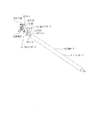
図1は本発明の第1の実施の形態における現像装置の要部を示す分解図、図4は本発明の第1の実施の形態における現像装置の供給ローラの断面図、図5は本発明の第1の実施の形態における現像装置の第1のスポンジの穴部53の中心における部分拡大断面図、図6は本発明の第1の実施の形態における現像装置のフレームの穴部62の中心における部分拡大断面図、図7は本発明の第1の実施の形態における現像装置の第2のスポンジの断面図、図8は本発明の第1の実施の形態における現像装置のワッシャーの断面図、図9は本発明の第1の実施の形態における現像装置の第2のスポンジがフレームの段差部によって保持された状態を示す断面図、図10は本発明の第1の実施の形態における現像装置の第1のスポンジとフレームの段差部によって保持された第2のスポンジとが当接する前の状態を示す断面図、図11は本発明の第1の実施の形態における現像装置の第1のスポンジとフレームの段差部によって保持された第2のスポンジとが当接したときの状態を示す断面図である。
1 is an exploded view showing a main part of the developing device according to the first embodiment of the present invention, FIG. 4 is a sectional view of a supply roller of the developing device according to the first embodiment of the present invention, and FIG. FIG. 6 is a partially enlarged cross-sectional view at the center of the
なお、前記供給ローラ34の端部の構成は、軸方向の両端において同様であるので、ここでは、一端における端部についてのみ説明するものとする。
Since the configuration of the end portion of the
図1に示されるように、供給ローラ34は、軸部としてのシャフト38と、該シャフト38の周囲に取り付けられたローラ部としてのシリコンスポンジ51とを備える。そして、供給ローラ34の端部において、シリコンスポンジ51の端部から軸方向に突出して露出したシャフト38にはワッシャー36が嵌(は)め込まれている。また、第1のスポンジ52は、前記シャフト38が挿入される穴部53を有し、前記ワッシャー36よりも供給ローラ34の軸方向端寄り、すなわち、前記ワッシャー36における反シリコンスポンジ51側に配設されている。したがって、ワッシャー36は、第1のスポンジ52とシリコンスポンジ51との間に位置する。シャフト38は、シャフト38の軸方向におけるフレーム43の外側(供給ローラ34の配置される反対側)に設けられたシャーシ35に形成された図示せぬ軸受け部によって回転自在に保持される。
As shown in FIG. 1, the
図1において、54は、シャフト38が挿入される穴部55を有する第2の封止部材としての第2のスポンジである。そして、保持部としてのフレーム43は、第2のスポンジ54を保持するための所定の高さの段差を有する段差部56と、第1のスポンジ52と当接する突当部57とを備える。
In FIG. 1,
図4に示されるように、供給ローラ34の外径、すなわち、シリコンスポンジ51の外径をD1とし、シャフト38の外径をD2とすると、供給ローラ34の諸元は以下のようになる。
As shown in FIG. 4, when the outer diameter of the
外径D1:φ15.4〔mm〕
外径D2:φ5.985〔mm〕
硬度:51±5度(アスカーF)
圧縮応力S25:45KPa
ここで、シリコンスポンジ51は、シリコンゴムを発泡成形して作製されたものであり、硬度は51±5度(アスカーF)であり、圧縮応力S25(試験片厚さの25〔%〕まで押し込んだ時の圧縮応力。JIS K 6400−2による。)は45KPa程度であることが望ましい。
Outer diameter D1: φ15.4 [mm]
Outer diameter D2: φ5.985 [mm]
Hardness: 51 ± 5 degrees (Asker F)
Compressive stress S 25: 45KPa
Here, the
図5に示されるように、第1のスポンジ52の厚さをt1とし、穴部53の径、すなわち、穴径をD3とすると、第1のスポンジ52の諸元は以下のようになる。なお、61は、供給ローラ34のシリコンスポンジ51と対向する面の反対の面であり、穴部53の内壁面には、摩擦の低減のため、飛散しない程度の少量の現像剤31が塗布されている。
As shown in FIG. 5, when the thickness of the
穴径D3:φ5.8〔mm〕
厚さt1:5〔mm〕
硬度:80±5度(アスカーF)
圧縮応力S25:70KPa
ここで、第1のスポンジ52の硬度及び弾性は第2のスポンジ54の硬度及び弾性よりも高く、硬度は80±5度(アスカーF)、圧縮応力S25は70KPa程度であることが望ましい。なお、硬度及び弾性は、ウレタンスポンジの作製時に使用する触媒及び発泡剤の量を調整することで変更することが可能となる。
Hole diameter D3: φ5.8 [mm]
Thickness t1: 5 [mm]
Hardness: 80 ± 5 degrees (Asker F)
Compressive stress S 25: 70KPa
Here, the hardness and elasticity of the
図6に示されるように、フレーム43は、段差部56と突当部57とを有し、段差部56はシャフト38が挿入される穴部62と、シャフト38の軸方向において第2のスポンジ54を規制する第1の規制部63と、シャフト38の周方向において第2のスポンジ54を規制する第2の規制部64とで構成される。そして、フレーム43の厚さをt2とし、段差部56の段差の高さをh9とし、第2の規制部64の径、すなわち、穴径をD4とし、穴部62の径、すなわち、穴径をD5とすると、フレーム43の諸元は以下のようになる。
As shown in FIG. 6, the
厚さt2:2.5〔mm〕
穴径D4:φ9〔mm〕
穴径D5:φ6.1〔mm〕
高さh9:1〔mm〕
図7に示されるように、第2のスポンジ54の厚さをt12とし、第2のスポンジ54の外径をD6とし、穴部55の径、すなわち、穴径をD7とすると、第2のスポンジ54の諸元は以下のようになる。なお、穴部55の内壁面には、摩擦の低減のため、飛散しない程度の少量の現像剤31が塗布されている。
Thickness t2: 2.5 [mm]
Hole diameter D4: φ9 [mm]
Hole diameter D5: φ6.1 [mm]
Height h9: 1 [mm]
As shown in FIG. 7, when the thickness of the
外径D6:φ9〔mm〕
穴径D7:φ6.2〔mm〕
厚さt12:1.5〔mm〕
硬度:40±5度(アスカーF)
圧縮応力S25:40KPa
ここで、厚さt12は、シャフト38の軸方向に関し段差部56の段差の高さh9よりも大きな寸法となっている。また、穴部55の穴径D7とシャフト38の外径D2との間には、D7>D2の関係が成立している。後述するように、第2のスポンジ54は、第1のスポンジ52によって圧縮されるので、その硬度及び弾性は第1のスポンジ52の硬度及び弾性よりも低く、硬度は40±5度(アスカーF)、圧縮応力S25は40KPa程度であることが望ましい。なお、硬度及び弾性は、ウレタンスポンジの作製時に使用する触媒及び発泡剤の量を調整することで変更することが可能となる。
Outer diameter D6: φ9 [mm]
Hole diameter D7: φ6.2 [mm]
Thickness t12: 1.5 [mm]
Hardness: 40 ± 5 degrees (Asker F)
Compressive stress S 25 : 40 KPa
Here, the thickness t <b> 12 is larger than the step height h <b> 9 of the
図8に示されるように、ワッシャー36の厚さをt3とし、外径をD8とし、内径をD9とすると、ワッシャー36の諸元は以下のようになる。
As shown in FIG. 8, when the thickness of the
外径D8:φ11〔mm〕
内径D9:φ6.1〔mm〕
厚さt3:0.25〔mm〕
材質:ポリエステルフィルム
ヤング率:4GP(JIS−7127による)
図9には、第2のスポンジ54がフレーム43の段差部56に保持された状態が示されている。この状態では、第2のスポンジ54は、段差部56の第1の規制部63によってシャフト38の軸方向に関する動きが規制され、段差部56の第2の規制部64によってシャフト38の周方向に関する動きが規制されている。
Outer diameter D8: φ11 [mm]
Inner diameter D9: φ6.1 [mm]
Thickness t3: 0.25 [mm]
Material: Polyester film Young's modulus: 4GP (according to JIS-7127)
FIG. 9 shows a state in which the
ここで、第2のスポンジ54の厚さt12は、段差部56の高さh9よりも大きく設定されているため、高さh13を有する突出部65が形成される。該突出部65の諸元は以下のようになる。
Here, since the thickness t12 of the
高さh13:0.5〔mm〕
突出部65の体積V1:16.71〔mm3 〕
図10には、第1のスポンジ52と、フレーム43の段差部56に保持された第2のスポンジ54とが当接する前の状態が示されている。この状態では、シャフト38の外径D2が穴部55の穴径D7より小さいため(D7>D2)、シャフト38と第2のスポンジ54との間に、高さh9の間隙66が形成される。該間隙66の諸元は以下のようになる。
Height h13: 0.5 [mm]
Volume V1 of the protrusion 65: 16.71 [mm 3 ]
FIG. 10 shows a state before the
間隙66の体積V2:2.06〔mm3 〕
図11には、第1のスポンジ52と、フレーム43の段差部56に保持された第2のスポンジ54とが当接した状態が示されている。この状態では、第2のスポンジ54は、第1のスポンジ52よりも低い硬度及び弾性を備え、段差部56の第1の規制部63によってシャフト38の軸方向に関する動きが規制され、段差部56の第2の規制部64によってシャフト38の周方向に関する動きが規制されているため、シャフト38の軸方向に圧縮され、突出部65の高さh13が0〔mm〕になる。したがって、第1のスポンジ52の面61が、フレーム43の突当部57に当接する。また、第2のスポンジ54が第2の規制部64によって周方向への圧縮方向が規制されることでシャフト38の周方向に圧縮される。第1のスポンジ52と第2のスポンジ54とが当接する前の状態ではV1>V2であるから、第1のスポンジ52と第2のスポンジ54とが当接することによって、間隙66の体積V2=0〔mm3 〕となり、穴部55の穴径D7はシャフト38の外径D2と等しくなる。したがって、第2のスポンジ54はシャフト38と密着する。
Volume V2 of the gap 66: 2.06 [mm 3 ]
FIG. 11 shows a state in which the
次に、前記構成の画像形成装置10の動作について説明する。
Next, the operation of the
図12は本発明の第1の実施の形態における現像装置の要部断面図、図13は従来の現像装置の要部断面図である。 FIG. 12 is a cross-sectional view of main parts of the developing device according to the first embodiment of the present invention, and FIG. 13 is a cross-sectional view of main parts of the conventional developing device.
まず、図示されないパーソナルコンピュータ等の上位装置からの印字指令を受け取ると、画像形成装置10は画像形成動作を開始する。そして、媒体トレイ15に収納された媒体16は、分離ローラ17によって1枚ずつ分離されて送り出され、搬送ローラ18a及び18bによって転写ベルト19に送られる。そして、各色に対応する現像装置11においては、感光ドラム13の表面に静電潜像が形成され、該静電潜像が現像されて現像剤像が形成され、感光ドラム13の表面上の現像剤像が、前記転写ベルト19によって搬送される媒体16に転写される。
First, upon receiving a print command from a host device such as a personal computer (not shown), the
この場合、現像装置11の供給ローラ34は、図示されない駆動源によって矢印34aで示される方向に回転させられ、現像ローラ33上に現像剤31を供給する。また、現像ローラ33は、図示されない駆動源によって矢印33aで示される方向に回転させられる。そして、現像ローラ33上の現像剤31は、現像ブレード40によって薄層化され、帯電させられる。
In this case, the
一方、図示されない駆動源によって矢印13eで示される方向に回転させられる感光体ドラム13の表面は、帯電ローラ41によって均一に帯電させられ、露光ヘッド14によって選択的に露光され、静電潜像が形成される。なお、露光された部分の電位は0〔V〕程度となる。そして、前記静電潜像に現像ローラ33上の現像剤31が供給されて現像され、現像剤像が形成される。
On the other hand, the surface of the
続いて、感光体ドラム13の表面に形成された現像剤像は、静電気力によって、感光体ドラム13の表面から転写ベルト19によって搬送される媒体16に転写される。なお、該媒体16に転写されずに感光体ドラム13の表面に残留した現像剤31は、クリーニングブレード42によって、感光体ドラム13の表面から掻(か)き落とされて除去される。そして、除去された現像剤31は、スパイラル67によって、廃現像剤として現像装置11の外部へ排出される。
Subsequently, the developer image formed on the surface of the
また、現像剤像が転写された媒体16は定着ユニット20に送り込まれる。そして、前記媒体16に転写された現像剤像は、熱及び圧力によって媒体16に定着させられる。定着ユニット20によって現像剤像が定着した媒体16は、排出ローラ21a、21b、22a及び22bによって画像形成装置10の外部に排出され、スタッカカバー23上に載置される。
Further, the medium 16 on which the developer image has been transferred is sent to the fixing
従来では、図13に示されるように、供給ローラ34の端部において、シリコンスポンジ51と第1のスポンジ52との間隙に現像剤31が進入した場合、第1のスポンジ52のフレーム43側(シリコンスポンジ51と反対側)にシールを行う機構が設けられていないため、現像剤31がフレーム43の外へ漏出することがあった。
Conventionally, as shown in FIG. 13, when the
しかし、本実施の形態によれば、図12に示されるように、供給ローラ34の端部において、シリコンスポンジ51と第1のスポンジ52との間隙に現像剤31が進入した場合であっても、第1のスポンジ52とフレーム43との間に第2のスポンジ54が配設され、かつ、第2のスポンジ54がシャフト38と密着しているので、現像剤31がフレーム43の外へ漏出することがない。
However, according to the present embodiment, as shown in FIG. 12, even when the
このように、本実施の形態においては、供給ローラ34のシリコンスポンジ51の端側に第1のスポンジ52が配設され、該第1のスポンジ52の反シリコンスポンジ51側に第2のスポンジ54が配設されている。そして、第2のスポンジ54は、第1のスポンジ52よりも低い硬度及び弾性を備え、フレーム43に形成された段差部56の第1の規制部63によってシャフト38の軸方向に関する動きを規制され、前記段差部56の第2の規制部64によってシャフト38の周方向に関する動きを規制されている。したがって、第1のスポンジ52と第2のスポンジ54とが当接すると、該第2のスポンジ54は、シャフト38の軸方向に圧縮され、突出部65の高さh13が0〔mm〕になり、第1のスポンジ52の面61がフレーム43の突当部57に当接する。
Thus, in the present embodiment, the
また、第1のスポンジ52と第2のスポンジ54とが当接すると、該第2のスポンジ54がシャフト38の周方向に圧縮され、第2のスポンジ54とシャフト38との間の間隙66の体積V2が0〔mm3 〕となり、第2のスポンジ54の穴部55の穴径D7がシャフト38の外径D2と等しくなるので、第2のスポンジ54はシャフト38と密着する。このように、第2のスポンジ54がシャフト38と密着するので、該シャフト38は、第2のスポンジ54によってシールされる。
Further, when the
これにより、供給ローラ34のシリコンスポンジ51の端と第1のスポンジ52との間に現像剤31が入ったとしても、該現像剤31がフレーム43の外へ、すなわち、外部へ漏出することはない。
Thus, even if the
また、長期の駆動の後にワッシャー36にがたつきが生じて、供給ローラ34のシリコンスポンジ51との間隙に現像剤31が入ったとしても、第2のスポンジ54によってシャフト38はシールされているので、長期に亘(わた)るシール性の確保を期待することができる。なお、本実施の形態においては、説明を簡略化するために供給ローラ34の軸方向における一端側についてのみ説明したが、他端側においても同様である。
Even if the
次に、本発明の第2の実施の形態について説明する。なお、第1の実施の形態と同じ構造を有するものについては、同じ符号を付与することによって、その説明を省略する。また、前記第1の実施の形態と同じ動作及び同じ効果についても、その説明を省略する。 Next, a second embodiment of the present invention will be described. In addition, about the thing which has the same structure as 1st Embodiment, the description is abbreviate | omitted by providing the same code | symbol. The description of the same operation and the same effect as those of the first embodiment is also omitted.
図14は本発明の第2の実施の形態における現像装置のフレームの断面図、図15は本発明の第2の実施の形態における第2のスポンジがフレームの段差部によって保持された状態を示す図、図16は本発明の第2の実施の形態における第1のスポンジとフレームの段差部によって保持された第2のスポンジとが当接する前の状態を示す図、図17は本発明の第2の実施の形態における第1のスポンジとフレームの段差部によって保持された第2のスポンジとが当接したときの状態を示す図である。 FIG. 14 is a cross-sectional view of the frame of the developing device according to the second embodiment of the present invention, and FIG. 15 shows a state in which the second sponge according to the second embodiment of the present invention is held by the step portion of the frame. FIG. 16 is a diagram showing a state before the first sponge and the second sponge held by the step portion of the frame abut on each other according to the second embodiment of the present invention. FIG. It is a figure which shows a state when the 1st sponge in 2nd Embodiment and the 2nd sponge hold | maintained by the level | step-difference part of a flame | frame contact | abutted.
本実施の形態においては、図14に示されるように、フレーム43に形成された段差部56は、シャフト38の軸方向に関して第1のスポンジ52から離れるに従って、シャフト38に近付くような傾斜71を有する。そして、フレーム43の諸元のうち、前記第1の実施の形態と異なる部分は、以下のようになる。
In the present embodiment, as shown in FIG. 14, the stepped
第1の規制部63から測定した傾斜71の長さL1:0.5〔mm〕
突当部57から傾斜71までの長さL2:0.5〔mm〕
第1の規制部63における径D10:φ8〔mm〕
図15には、第2のスポンジ54がフレーム43の段差部56に保持された状態が示されている。ここで、第2のスポンジ54の厚さt12が、突当部57から傾斜71までの長さL2よりも大きく設定されているため、高さh46を有する突出部65が形成される。該突出部65の諸元は以下のようになる。
Length L1: 0.5 [mm] of the
Length L2 from the
Diameter D10 at first restricting portion 63: φ8 [mm]
FIG. 15 shows a state in which the
高さh46:1〔mm〕
突出部65の体積V3:33.42〔mm3 〕
図16には、第1のスポンジ52と、フレーム43の段差部56に保持された第2のスポンジ54とが当接する前の状態が示されている。この状態では、シャフト38の外径D2が穴部55の穴径D7より小さいため(D7>D2)、シャフト38と第2のスポンジ54との間に、高さL2の間隙72が形成され、シャフト38と傾斜71との間に高さL1の間隙73が形成される。前記間隙72及び73の諸元は以下のようになる。
Height h46: 1 [mm]
Volume V3 of the protrusion 65: 33.42 [mm 3 ]
FIG. 16 shows a state before the
間隙72の体積V4:1.03〔mm3 〕
間隙73の体積V5:14.34〔mm3 〕
図17には、第1のスポンジ52と、フレーム43の段差部56に保持された第2のスポンジ54とが当接した状態が示されている。この状態では、第2のスポンジ54は、第1のスポンジ52よりも低い硬度及び弾性を備え、段差部56の第1の規制部63によってシャフト38の軸方向に関する動きが規制され、段差部56の第2の規制部64によってシャフト38の周方向に関する動きが規制されているため、シャフト38の軸方向に圧縮され、突出部65の高さh46が0〔mm〕になる。したがって、第1のスポンジ52の面61が、フレーム43の突当部57に当接する。また、第2のスポンジ54がシャフト38の周方向に圧縮され、第1のスポンジ52と第2のスポンジ54とが当接する前の状態ではV3>V4+V5であるから、第1のスポンジ52と第2のスポンジ54とが当接することによって、間隙72及び73の体積V4+V5=0〔mm3 〕となり、穴部55の穴径D7はシャフト38の外径D2と等しくなる。したがって、第2のスポンジ54はシャフト38と密着する。前記突出部65並びに間隙66、72及び73の諸元は以下のようになる。
Volume V4 of the gap 72: 1.03 [mm 3 ]
Volume V5 of the gap 73: 14.34 [mm 3 ]
FIG. 17 shows a state in which the
V1−V2=14.65〔mm3 〕
V3−(V4+V5)=18.05〔mm3 〕
また、段差部56が、シャフト38の軸方向に関して第1のスポンジ52から離れるに従ってシャフト38に近付くような傾斜71を有するので、第2のスポンジ54は、シャフト38の軸方向に圧縮されるときに傾斜71に密着しながら挿入される。したがって、第1のスポンジ52と第2のスポンジ54とが当接すると、該第2のスポンジ54は、シャフト38の周方向により強く圧縮されることを期待することができる。
V1−V2 = 14.65 [mm 3 ]
V3− (V4 + V5) = 18.05 [mm 3 ]
Further, since the stepped
なお、その他の点の構成については、前記第1の実施の形態と同様であるので、その説明を省略する。 Since the configuration of other points is the same as that of the first embodiment, description thereof is omitted.
次に、本実施の形態における画像形成装置10の動作について説明する。
Next, the operation of the
前記第1の実施の形態と同様に、供給ローラ34の端部において、シリコンスポンジ51と第1のスポンジ52との間隙に現像剤31が進入した場合であっても、第1のスポンジ52とフレーム43との間に第2のスポンジ54が配設され、かつ、該第2のスポンジ54がシャフト38と密着しているので、現像剤31がフレーム43の外へ漏出することがない。
Similar to the first embodiment, even when the
なお、その他の点の動作については、前記第1の実施の形態と同様であるので、その説明を省略する。 Other operations are the same as those in the first embodiment, and a description thereof will be omitted.
このように、本実施の形態においては、突出部65の体積V3と、シャフト38と第2のスポンジ54との間、及び、シャフト38と傾斜71との間に形成される間隙72及び73の体積V4及びV5との差分が、V3−(V4+V5)=18.05〔mm3 〕という大きな値となるので、第1のスポンジ52と第2のスポンジ54とが当接したときに該第2のスポンジ54が圧縮される量は大きな値となる。
Thus, in the present embodiment, the
なお、前記第1の実施の形態において、第1のスポンジ52と第2のスポンジ54とが当接したときに該第2のスポンジ54が圧縮される量は、V1−V2=14.65〔mm3 〕である。
In the first embodiment, when the
また、段差部56が、シャフト38の軸方向に関して第1のスポンジ52から離れるに従ってシャフト38に近付くような傾斜71を有するので、第2のスポンジ54は、シャフト38の軸方向に圧縮されるときに傾斜71に密着しながら挿入される。
Further, since the stepped
したがって、第1のスポンジ52と第2のスポンジ54とが当接すると、該第2のスポンジ54は、シャフト38の周方向により強く圧縮されるので、前記第1の実施の形態と比較して、より強いシール性を確保することを期待することができる。その他の点の効果については、前記第1の実施の形態と同様であるので、その説明を省略する。
Therefore, when the
なお、前記第1及び第2の本実施の形態においては、ローラ部材が供給ローラ34である場合について説明したが、端部をシール部材によってシールされていれば、ローラ部材は、異なる種類のローラ(例えば、現像ローラ33)であってもよい。また、第1の封止部材及び第2の封止部材としての第1のスポンジ52及び第2のスポンジ54は、ウレタンスポンジに限らず、ポリエチレンスポンジ、ゴムスポンジ等であってもよい。さらに、前記第1及び第2の本実施の形態における現像装置11は、画像形成装置10に実装されたものとして説明したが、複写機、ファクシミリ機、MFP等に用いられる現像装置11であってもよい。
In the first and second embodiments, the case where the roller member is the
また、本発明は前記実施の形態に限定されるものではなく、本発明の趣旨に基づいて種々変形させることが可能であり、それらを本発明の範囲から排除するものではない。 The present invention is not limited to the above-described embodiment, and various modifications can be made based on the spirit of the present invention, and they are not excluded from the scope of the present invention.
本発明は、現像装置及び画像形成装置に利用することができる。 The present invention can be used in a developing device and an image forming apparatus.
10 画像形成装置
11、11a、11b、11c、11d 現像装置
34 供給ローラ
36 ワッシャー
38 シャフト
43 フレーム
51 シリコンスポンジ
52 第1のスポンジ
53、55、62 穴部
54 第2のスポンジ
56 段差部
57 突当部
61 面
63 第1の規制部
64 第2の規制部
71 傾斜
DESCRIPTION OF
Claims (5)
前記軸部が挿入される穴部を備え、前記ローラ部の端部に対向するように配設される第1の封止部材と、
前記軸部が挿入される穴部を備え、前記第1の封止部材の前記ローラ部材と反対の面に当接するように配設される第2の封止部材と、
該第2の封止部材を保持する段差部と、前記第1の封止部材と当接する突当部とを備える保持部と、
を有し、
前記第1の封止部材は、前記第2の封止部材よりも硬度が高く、
前記段差部は、前記軸部が挿入される穴部と、前記軸部の軸方向に関する前記第2の封止部材の動きを規制する第1の規制部と、前記軸部の周方向に関する前記第2の封止部材を規制する第2の規制部とを備え、
前記第2の封止部材は、前記軸部の軸方向に関する寸法が前記段差部の前記軸部の軸方向に関する寸法より大きく、前記段差部内に圧縮されて組み立てられる
ことを特徴とする現像装置。 A roller member comprising a roller portion and a shaft portion protruding from an end portion of the roller portion;
A first sealing member provided with a hole portion into which the shaft portion is inserted, and disposed to face an end portion of the roller portion;
A second sealing member provided with a hole portion into which the shaft portion is inserted, and disposed so as to abut on a surface of the first sealing member opposite to the roller member;
A holding portion comprising a stepped portion for holding the second sealing member, and an abutting portion in contact with the first sealing member;
Have
The first sealing member is higher in hardness than the second sealing member,
The step portion includes a hole portion into which the shaft portion is inserted, a first restricting portion that restricts the movement of the second sealing member with respect to the axial direction of the shaft portion, and the circumferential direction of the shaft portion. A second restricting portion for restricting the second sealing member,
The developing device, wherein the second sealing member has a dimension in the axial direction of the shaft portion larger than a dimension in the axial direction of the shaft portion of the step portion, and is compressed and assembled in the step portion.
前記軸部が挿入される穴部を備え、前記ローラ部の端部に対向するように配設される第1の封止部材と、
前記軸部が挿入される穴部を備え、前記第1の封止部材の前記ローラ部材と反対の面に当接するように配設される第2の封止部材と、
該第2の封止部材を保持する段差部と、前記第1の封止部材と当接する突当部とを備える保持部と、
を有し、
前記段差部は、前記軸部が挿入される穴部と、前記軸部の軸方向に関する前記第2の封止部材の動きを規制する第1の規制部と、前記軸部の周方向に関する前記第2の封止部材を規制する第2の規制部と、前記軸部の軸方向に関して第1の封止部材から離れるに従って前記軸部に近付くような傾斜とを備え、
前記第2の封止部材は、前記軸部の軸方向に関する寸法が前記段差部の前記軸部の軸方向に関する寸法より大きく、前記段差部内に圧縮されて組み立てられる
ことを特徴とする現像装置。 A roller member comprising a roller portion and a shaft portion protruding from an end portion of the roller portion;
A first sealing member provided with a hole portion into which the shaft portion is inserted, and disposed to face an end portion of the roller portion;
A second sealing member provided with a hole portion into which the shaft portion is inserted, and disposed so as to abut on a surface of the first sealing member opposite to the roller member;
A holding portion comprising a stepped portion for holding the second sealing member, and an abutting portion in contact with the first sealing member;
Have
The step portion includes a hole portion into which the shaft portion is inserted, a first restricting portion that restricts the movement of the second sealing member with respect to the axial direction of the shaft portion, and the circumferential direction of the shaft portion. A second restricting portion that restricts the second sealing member, and an inclination that approaches the shaft portion as it moves away from the first sealing member with respect to the axial direction of the shaft portion,
The dimension of the second sealing member in the axial direction of the shaft portion is larger than the dimension of the stepped portion in the axial direction of the shaft portion, and is compressed and assembled in the stepped portion.
A developing device.
Priority Applications (2)
| Application Number | Priority Date | Filing Date | Title |
|---|---|---|---|
| JP2012186106A JP5651144B2 (en) | 2012-08-27 | 2012-08-27 | Developing device and image forming apparatus |
| US13/969,639 US9069292B2 (en) | 2012-08-27 | 2013-08-19 | Development device and image formation apparatus |
Applications Claiming Priority (1)
| Application Number | Priority Date | Filing Date | Title |
|---|---|---|---|
| JP2012186106A JP5651144B2 (en) | 2012-08-27 | 2012-08-27 | Developing device and image forming apparatus |
Publications (3)
| Publication Number | Publication Date |
|---|---|
| JP2014044282A JP2014044282A (en) | 2014-03-13 |
| JP2014044282A5 JP2014044282A5 (en) | 2014-04-24 |
| JP5651144B2 true JP5651144B2 (en) | 2015-01-07 |
Family
ID=50148080
Family Applications (1)
| Application Number | Title | Priority Date | Filing Date |
|---|---|---|---|
| JP2012186106A Expired - Fee Related JP5651144B2 (en) | 2012-08-27 | 2012-08-27 | Developing device and image forming apparatus |
Country Status (2)
| Country | Link |
|---|---|
| US (1) | US9069292B2 (en) |
| JP (1) | JP5651144B2 (en) |
Families Citing this family (3)
| Publication number | Priority date | Publication date | Assignee | Title |
|---|---|---|---|---|
| EP3100119B1 (en) * | 2014-01-31 | 2019-08-21 | HP Indigo B.V. | Ink developer unit |
| JP5934733B2 (en) | 2014-03-06 | 2016-06-15 | 富士重工業株式会社 | Steering device |
| JP2021021882A (en) * | 2019-07-30 | 2021-02-18 | キヤノン株式会社 | Developer supply container |
Family Cites Families (13)
| Publication number | Priority date | Publication date | Assignee | Title |
|---|---|---|---|---|
| JP3092514B2 (en) * | 1996-05-28 | 2000-09-25 | ブラザー工業株式会社 | Developing device and image forming apparatus including developing device |
| JP3786655B2 (en) * | 1996-10-22 | 2006-06-14 | 株式会社リコー | Toner supply container |
| JP2001289327A (en) * | 2000-04-05 | 2001-10-19 | Ricoh Co Ltd | Sealing structure |
| JP2004226695A (en) * | 2003-01-23 | 2004-08-12 | Ricoh Co Ltd | Bearing seal structure of development device of image forming apparatuses, the development device, and the image forming apparatus |
| JP4342834B2 (en) * | 2003-05-21 | 2009-10-14 | 京セラミタ株式会社 | Toner supply device and seal structure |
| JP2005077660A (en) * | 2003-08-29 | 2005-03-24 | Kyocera Mita Corp | Toner supply container and image forming apparatus |
| JP4356021B2 (en) * | 2005-03-09 | 2009-11-04 | 村田機械株式会社 | Development device |
| JP2007065531A (en) * | 2005-09-02 | 2007-03-15 | Murata Mach Ltd | Developing unit and image forming apparatus |
| JP2007193065A (en) * | 2006-01-19 | 2007-08-02 | Konica Minolta Business Technologies Inc | Cartridge and image forming apparatus |
| JP2008203646A (en) * | 2007-02-21 | 2008-09-04 | Fuji Xerox Co Ltd | Developing device |
| EP2045668B1 (en) * | 2007-10-02 | 2014-11-12 | Brother Kogyo Kabushiki Kaisha | Developer cartridge and developing unit |
| JP2010032957A (en) | 2008-07-31 | 2010-02-12 | Oki Data Corp | Image forming unit and image forming apparatus |
| JP5467656B2 (en) * | 2011-09-20 | 2014-04-09 | 株式会社沖データ | Developing device and image forming apparatus |
-
2012
- 2012-08-27 JP JP2012186106A patent/JP5651144B2/en not_active Expired - Fee Related
-
2013
- 2013-08-19 US US13/969,639 patent/US9069292B2/en not_active Expired - Fee Related
Also Published As
| Publication number | Publication date |
|---|---|
| JP2014044282A (en) | 2014-03-13 |
| US20140056610A1 (en) | 2014-02-27 |
| US9069292B2 (en) | 2015-06-30 |
Similar Documents
| Publication | Publication Date | Title |
|---|---|---|
| US8953974B2 (en) | Image forming apparatus | |
| JP2008096810A (en) | Toner conveying device, process cartridge and image forming apparatus | |
| US7463843B2 (en) | Developing device | |
| KR20130021338A (en) | Electrophotographic image forming apparatus and process cartridge | |
| JP5738173B2 (en) | Developer container, image forming unit, and image forming apparatus | |
| JP4538026B2 (en) | Charging device, image forming unit, and image forming apparatus | |
| JP5651144B2 (en) | Developing device and image forming apparatus | |
| US9389540B2 (en) | End sealing and magnetic field truncation of a magnetic roll of a dual component development electrophotographic image forming device | |
| JP2008257213A (en) | Developing device, process cartridge, and image forming apparatus | |
| JP2007163790A (en) | Developer container and image forming apparatus | |
| JP2012103418A (en) | Developer storage body, image forming unit and image forming apparatus | |
| JP4846831B2 (en) | Toner cartridge and image forming apparatus using the same | |
| JP5020109B2 (en) | Developing device, process cartridge, image forming apparatus, color image forming apparatus | |
| JP4284987B2 (en) | Packaging method of image forming apparatus at shipment | |
| JP2014191309A (en) | Developing roller and developing device | |
| JP2011191420A (en) | Toner cartridge and image forming apparatus including the same | |
| JP4856016B2 (en) | Developing device, process cartridge, and image forming apparatus | |
| US7647010B2 (en) | Toner cartridge and image forming apparatus | |
| US10401757B2 (en) | Developing device having a bearing supported feeding screw | |
| JP5534415B2 (en) | Developing device, process cartridge including the developing device, and image forming apparatus including the developing device or the process cartridge | |
| JP4804933B2 (en) | Development device | |
| JP5542235B2 (en) | Developer container and image forming apparatus having the same | |
| JP2015105970A (en) | Developer cartridge, image forming unit, and image forming apparatus | |
| JP2009244451A (en) | Developing device, and image forming apparatus equipped therewith | |
| JP6033596B2 (en) | Image forming apparatus and toner supply device |
Legal Events
| Date | Code | Title | Description |
|---|---|---|---|
| A521 | Request for written amendment filed |
Free format text: JAPANESE INTERMEDIATE CODE: A523 Effective date: 20140220 |
|
| A621 | Written request for application examination |
Free format text: JAPANESE INTERMEDIATE CODE: A621 Effective date: 20140220 |
|
| A977 | Report on retrieval |
Free format text: JAPANESE INTERMEDIATE CODE: A971007 Effective date: 20140729 |
|
| A131 | Notification of reasons for refusal |
Free format text: JAPANESE INTERMEDIATE CODE: A131 Effective date: 20140812 |
|
| A521 | Request for written amendment filed |
Free format text: JAPANESE INTERMEDIATE CODE: A523 Effective date: 20141006 |
|
| TRDD | Decision of grant or rejection written | ||
| A01 | Written decision to grant a patent or to grant a registration (utility model) |
Free format text: JAPANESE INTERMEDIATE CODE: A01 Effective date: 20141028 |
|
| A61 | First payment of annual fees (during grant procedure) |
Free format text: JAPANESE INTERMEDIATE CODE: A61 Effective date: 20141114 |
|
| R150 | Certificate of patent or registration of utility model |
Ref document number: 5651144 Country of ref document: JP Free format text: JAPANESE INTERMEDIATE CODE: R150 |
|
| LAPS | Cancellation because of no payment of annual fees |