JP5649991B2 - Beauty equipment - Google Patents

Beauty equipment Download PDF

Info

Publication number
JP5649991B2
JP5649991B2 JP2011012558A JP2011012558A JP5649991B2 JP 5649991 B2 JP5649991 B2 JP 5649991B2 JP 2011012558 A JP2011012558 A JP 2011012558A JP 2011012558 A JP2011012558 A JP 2011012558A JP 5649991 B2 JP5649991 B2 JP 5649991B2
Authority
JP
Japan
Prior art keywords
driving
blowing means
cooling
conversion element
thermoelectric conversion
Prior art date
Legal status (The legal status is an assumption and is not a legal conclusion. Google has not performed a legal analysis and makes no representation as to the accuracy of the status listed.)
Active
Application number
JP2011012558A
Other languages
Japanese (ja)
Other versions
JP2012152306A5 (en
JP2012152306A (en
Inventor
岡本 祐介
祐介 岡本
亘祐 松尾
亘祐 松尾
Current Assignee (The listed assignees may be inaccurate. Google has not performed a legal analysis and makes no representation or warranty as to the accuracy of the list.)
Hitachi Maxell Energy Ltd
Original Assignee
Hitachi Maxell Energy Ltd
Priority date (The priority date is an assumption and is not a legal conclusion. Google has not performed a legal analysis and makes no representation as to the accuracy of the date listed.)
Filing date
Publication date
Application filed by Hitachi Maxell Energy Ltd filed Critical Hitachi Maxell Energy Ltd
Priority to JP2011012558A priority Critical patent/JP5649991B2/en
Publication of JP2012152306A publication Critical patent/JP2012152306A/en
Publication of JP2012152306A5 publication Critical patent/JP2012152306A5/ja
Application granted granted Critical
Publication of JP5649991B2 publication Critical patent/JP5649991B2/en
Active legal-status Critical Current
Anticipated expiration legal-status Critical

Links

Images

Description

本発明は、肌を冷やす美容器具に関する。   The present invention relates to a beauty device for cooling the skin.

この種の美容器具として、美容器本体のヘッドの内面にペルチェ素子を配置しておき、ペルチェ素子で冷却された冷却板で顔肌を冷却して、肌の状態を向上する美容器具が公知である(特許文献1)。そこでは、ペルチェ素子の高温面側に熱良導体からなる放熱基台を接合し、さらに放熱基台の外面に放熱フィンを接合している。また、送風手段で生成した冷却風で放熱フィンを冷却することによりペルチェ素子の放熱を促進して、同素子が過熱状態に陥るのを防止している。冷却風は、美容器本体のマッサージヘッドの周囲に開口した吸込み口から吸い込まれ、美容器本体の下端に開口した排出口から外部へ放出される。なお、放熱フィンは、筒体の周面に一群のフィンを放射状に突設して構成してある。   As this type of beauty device, a beauty device is known in which a Peltier device is arranged on the inner surface of the head of a beauty device body, and the facial skin is cooled by a cooling plate cooled by the Peltier device to improve the skin condition. Yes (Patent Document 1). In this case, a heat radiation base made of a good heat conductor is joined to the high temperature surface side of the Peltier element, and heat radiation fins are joined to the outer surface of the heat radiation base. Further, by cooling the heat dissipating fins with the cooling air generated by the air blowing means, heat dissipation of the Peltier element is promoted and the element is prevented from falling into an overheated state. The cooling air is sucked in from a suction port opened around the massage head of the beauty device body, and is discharged to the outside from a discharge port opened in the lower end of the beauty device body. In addition, the radiation fin is configured by radially projecting a group of fins on the peripheral surface of the cylindrical body.

同様の美容器具は特許文献2にも見ることができ、そこでは、顔肌をプローブで交互に加熱し、あるいは冷却しながら美容器本体を振動させて、美容効果を向上できるようにしている。そのために、モーターと、その出力軸に固定される偏心重りとからなるバイブレータを美容器本体の内部に配置している。美容器本体の内部には、ペルチェ素子の放熱を促進する送風手段が設けてある。   A similar beauty device can also be found in Patent Document 2, in which the beauty skin body is vibrated while alternately heating or cooling the facial skin with a probe so that the beauty effect can be improved. For this purpose, a vibrator composed of a motor and an eccentric weight fixed to the output shaft is arranged inside the cosmetic device body. Inside the beauty machine main body is provided with a blowing means for promoting heat dissipation of the Peltier element.

さらに、特許文献3の美容器具においては、ヘッドをペルチェ素子で冷却し、肌面に微弱なパルス電流を通電することにより、化粧水等をイオン導入作用によって肌に浸透できるようにしている。   Furthermore, in the beauty device of Patent Document 3, the head is cooled by a Peltier element, and a weak pulse current is applied to the skin surface, so that skin lotion or the like can penetrate into the skin by an ion introduction effect.

特許第3142860号公報(第2頁左欄20〜27行、第1図)Japanese Patent No. 3142860 (page 2, left column, lines 20 to 27, FIG. 1) 特開2001−190586号公報(段落番号0015、図1)Japanese Patent Laying-Open No. 2001-190586 (paragraph number 0015, FIG. 1) 特開2002−345976号公報(段落番号0021、図7)JP 2002-345976 (paragraph number 0021, FIG. 7)

特許文献3の美容器具では、放熱促進用の送風手段が設けられず、ヘッドを冷却するまでに時間を要する。特許文献1および特許文献2の美容器具では、放熱促進用の送風手段は設けられているが、冷却されたヘッドを肌面に接触させて冷却の手入れを行うときも送風手段が通常の回転数で回り続けていれば、その分、電力を消費する。また、送風手段や、それを駆動するモーターから発する耳障りな音を伴うため、安らかな気持ちで手入れを行うことができない。
また、特許文献1の美容器具では、ペルチェ素子の放熱作用を促進するために、美容器本体の内部に送風手段を配置し、美容器本体の上下に冷却風の吸込み口と排出口とを開口している。そのため、単に冷却された冷却板を顔肌に押当てて冷却する限りは問題ないが、特許文献3の美容器具のように、化粧水を併用して肌面の冷却を行うような場合に問題を生じる。詳しくは、化粧水が冷却風の吸込み口や排出口から美容器本体の内部に入り込み、美容器本体の内部に配置した回路基板や、回路基板に実装された電子部品等に付着して、回路の短絡や、誤作動を生じるおそれがある。また、この種の美容器本体の内部に配置した回路基板には、ペルチェ素子や送風手段の駆動状態を制御する制御回路、あるいはイオン導入用のパルス電流を生成するための電流調整回路などが組み込んであるが、回路基板に実装された電子部品が熱交換後の温風に晒されて過熱状態に陥り、誤作動を生じるおそれがある。
In the beauty device of Patent Document 3, no air blowing means for promoting heat dissipation is provided, and it takes time to cool the head. In the beauty instruments of Patent Document 1 and Patent Document 2, the air blowing means for promoting heat dissipation is provided, but the air blowing means is also operated at the normal rotation speed when cooling the head by bringing the cooled head into contact with the skin surface. If it keeps running, it will consume more power. Moreover, since it is accompanied by an annoying sound emitted from the air blowing means and the motor driving the air blowing means, it cannot be maintained with a peaceful feeling.
Moreover, in the beauty instrument of patent document 1, in order to accelerate | stimulate the thermal radiation effect | action of a Peltier device, the ventilation means is arrange | positioned inside a beauty instrument main body, and the suction inlet and discharge outlet of cooling air are opened on the upper and lower sides of a beauty instrument main body. doing. Therefore, there is no problem as long as the cooled cooling plate is simply pressed against the face skin to cool, but it is problematic when the skin surface is cooled together with the skin lotion like the beauty device of Patent Document 3. Produce. Specifically, the skin lotion enters the interior of the beauty device main body through the cooling air inlet and outlet, adheres to the circuit board disposed inside the beauty device main body, electronic components mounted on the circuit board, etc. May cause a short circuit or malfunction. In addition, a control circuit for controlling the driving state of the Peltier element and the air blowing means, a current adjusting circuit for generating a pulse current for ion introduction, and the like are incorporated in the circuit board disposed inside this type of beauty device body. However, the electronic component mounted on the circuit board may be exposed to the warm air after heat exchange and fall into an overheated state, resulting in malfunction.

本発明の目的は、ヘッドの冷却準備時間を短くするとともに、電力消費量を低減できる美容器具を提供することにある。
本発明の目的は、化粧水等の液体がたとえ本体ケースの内部に入り込んだとしても、制御回路や、制御回路の基板に実装された電子部品等に化粧水等の液体が付着するのを防止でき、さらに、電子部品が過熱状態に陥るのを防止して、安全性と信頼性を向上できる美容器具を提供することにある。
本発明の目的は、熱電変換素子から放出される熱をより効果的に排出して、美容器具が過熱状態に陥るのを解消でき、美容器具が適正な使用時間を越えて使用されるような場合であっても、ユーザーの安全性を確保し保護できる美容器具を提供することにある。
An object of the present invention is to provide a beauty device that can shorten the cooling preparation time of the head and reduce power consumption.
The object of the present invention is to prevent liquid such as lotion from adhering to the control circuit and electronic components mounted on the control circuit board even if liquid such as lotion enters the inside of the main body case. Further, it is an object of the present invention to provide a beauty device capable of preventing safety of electronic components from being overheated and improving safety and reliability.
An object of the present invention is to more effectively discharge the heat released from the thermoelectric conversion element, so that the beauty tool can be prevented from falling into an overheated state, and the beauty tool can be used beyond an appropriate usage time. Even if it is a case, it is providing the beauty instrument which can ensure and protect a user's safety.

本発明の美容器具は、本体ケース1と、肌面を冷却するヘッド2と、ヘッド2を冷却するための熱電変換素子44を含む冷却部12と、冷却部12に接続される放熱用のヒートシンク30と、ヒートシンク30に熱交換風を供給する送風手段31とを備えている。本体ケース1に設けられるスイッチ3・4の操作により、熱電変換素子44および送風手段31の駆動が開始され、所定時間が経過すると送風手段31の駆動が停止され、さらに所定時間が経過すると熱電変換素子44の駆動が停止される。   The beauty instrument of the present invention includes a main body case 1, a head 2 for cooling the skin surface, a cooling unit 12 including a thermoelectric conversion element 44 for cooling the head 2, and a heat sink for heat dissipation connected to the cooling unit 12. 30 and a blower means 31 for supplying heat exchange air to the heat sink 30. The operation of the switches 3 and 4 provided in the main body case 1 starts driving of the thermoelectric conversion element 44 and the air blowing means 31. When a predetermined time elapses, the driving of the air blowing means 31 is stopped, and when the predetermined time elapses, the thermoelectric conversion is performed. The driving of the element 44 is stopped.

本発明の美容器具は、本体ケース1に設けられるスイッチ3・4の操作により、熱電変換素子44および送風手段31の駆動が開始され、所定時間が経過すると送風手段31の駆動が制限され、さらに所定時間が経過すると熱電変換素子44および送風手段31の駆動が停止される。   In the beauty tool of the present invention, the operation of the thermoelectric conversion element 44 and the air blowing means 31 is started by the operation of the switches 3 and 4 provided in the main body case 1, and the driving of the air blowing means 31 is restricted when a predetermined time elapses. When the predetermined time has elapsed, the driving of the thermoelectric conversion element 44 and the air blowing means 31 is stopped.

また、上記一連の動作が、連続して所定回数繰り返された場合、スイッチ3・4の操作により、熱電変換素子44および送風手段31の駆動が開始され、所定時間が経過しても熱電変換素子44および送風手段31が駆動し続け、さらに所定時間が経過すると熱電変換素子44および送風手段31の駆動が停止される。   In addition, when the above series of operations is repeated a predetermined number of times in succession, driving of the thermoelectric conversion element 44 and the air blowing means 31 is started by the operation of the switches 3 and 4, and the thermoelectric conversion element even if a predetermined time elapses. 44 and the air blowing means 31 continue to be driven, and when a predetermined time elapses, the driving of the thermoelectric conversion element 44 and the air blowing means 31 is stopped.

また、上記一連の動作が、連続して所定回数繰り返された場合、スイッチ3・4の操作により、熱電変換素子44および送風手段31の駆動が開始され、所定時間が経過しても熱電変換素子44および送風手段31が駆動し続け、さらに所定時間が経過すると熱電変換素子44の駆動が停止され、さらに所定時間が経過すると送風手段31の駆動が停止される。   In addition, when the above series of operations is repeated a predetermined number of times in succession, driving of the thermoelectric conversion element 44 and the air blowing means 31 is started by the operation of the switches 3 and 4, and the thermoelectric conversion element even if a predetermined time elapses. 44 and the air blowing means 31 continue to be driven, and when the predetermined time elapses, the driving of the thermoelectric conversion element 44 is stopped, and when the predetermined time elapses, the driving of the air blowing means 31 is stopped.

また、熱電変換素子44の駆動が停止された後、再び送風手段31の駆動が開始され、所定時間の経過後、送風手段31の駆動が停止される。   In addition, after the driving of the thermoelectric conversion element 44 is stopped, the driving of the blowing unit 31 is started again, and after the predetermined time has elapsed, the driving of the blowing unit 31 is stopped.

また、本体ケース1に発光表示手段6dを備え、スイッチ3・4の操作により、熱電変換素子44および送風手段31の駆動が開始されたときに発光表示手段6dが点滅駆動となり、所定時間が経過して送風手段31の駆動が停止されたときに発光表示手段6dが点灯駆動となり、さらに所定時間が経過して熱電変換素子44および送風手段31の駆動が停止されたときに発光表示手段6dの駆動を停止した。   Also, the main body case 1 is provided with a light emitting display means 6d, and when the operation of the switches 3 and 4 starts driving the thermoelectric conversion element 44 and the air blowing means 31, the light emitting display means 6d is driven to blink, and a predetermined time has elapsed. When the driving of the air blowing means 31 is stopped, the light emitting display means 6d is turned on, and when the driving of the thermoelectric conversion element 44 and the air blowing means 31 is stopped after a predetermined time has elapsed, the light emitting display means 6d is turned on. The drive was stopped.

また、本体ケース1の内部に発音表示手段6dを有し、所定時間が経過して送風手段31の駆動が停止されたときに発音表示手段 を駆動する。   The main body case 1 has a sound generation display means 6d, and drives the sound generation display means when the driving of the air blowing means 31 is stopped after a predetermined time has elapsed.

また、本発明に係る美容器具は、図1に示すように、本体ケース1と、肌面を冷却するヘッド2と、ヘッド2を冷却するための熱電変換素子44を含む冷却部12と、冷却部12に接続される放熱用のヒートシンク30と、ヒートシンク30に熱交換風を供給する送風手段31とを備えている。本体ケース1の内部に、熱電変換素子44の駆動を制御する制御回路87が配置される電気部品エリア15と、ヒートシンク30および送風手段31が配置される通風エリア13を有する。通風エリア13を形成する壁には空気の吸込み口61と排出口62を開口する。通風エリア13と電気部品エリア15は、本体ケース1の内部に固定したカバー体18で区画する。   Further, as shown in FIG. 1, the beauty tool according to the present invention includes a main body case 1, a head 2 for cooling the skin surface, a cooling unit 12 including a thermoelectric conversion element 44 for cooling the head 2, The heat sink 30 for heat radiation connected to the section 12 and the air blowing means 31 for supplying heat exchange air to the heat sink 30 are provided. The main body case 1 has an electrical component area 15 in which a control circuit 87 for controlling driving of the thermoelectric conversion element 44 is disposed, and a ventilation area 13 in which the heat sink 30 and the air blowing means 31 are disposed. An air inlet 61 and an outlet 62 are opened in the wall forming the ventilation area 13. The ventilation area 13 and the electrical component area 15 are partitioned by a cover body 18 fixed inside the main body case 1.

冷却部12は、本体ケース1の上部に配置する。熱電変換素子44の高温面側に、熱電変換素子44の高温面側で発生する熱を放出するヒートシンク30を配置する。ヒートシンク30は、冷却部12からカバー体18の外面にわたって縦長に配置する。   The cooling unit 12 is disposed on the upper part of the main body case 1. A heat sink 30 that releases heat generated on the high temperature surface side of the thermoelectric conversion element 44 is disposed on the high temperature surface side of the thermoelectric conversion element 44. The heat sink 30 is arranged vertically from the cooling unit 12 to the outer surface of the cover body 18.

ヒートシンク30の下方に冷却風を送給する送風手段31を配置する。ヒートシンク30は、板状のシンクベース54と、シンクベース54に突設される多数個のフィン55とを備えている。カバー体18の外面の上部をシンクベース54で覆う。   Blower means 31 for supplying cooling air is disposed below heat sink 30. The heat sink 30 includes a plate-shaped sink base 54 and a large number of fins 55 protruding from the sink base 54. The upper part of the outer surface of the cover body 18 is covered with a sink base 54.

シンクベース54の上下中途部に段違い部57を形成する。   A stepped portion 57 is formed in the upper and lower middle portion of the sink base 54.

シンクベース54と、同ベース54に対向する本体ケース1の周壁とで挟まれる熱交換通路60を、その通路断面積がヒートシンク30の上部から下部へ向かって小さくなるように形成する。   A heat exchange passage 60 sandwiched between the sink base 54 and the peripheral wall of the main body case 1 facing the base 54 is formed so that the cross-sectional area of the passage decreases from the upper part to the lower part of the heat sink 30.

シンクベース54と、同ベース54に対向するカバー体18との間に、熱交換通路60の前後隙間より小さな通風隙間63を設ける。   Between the sink base 54 and the cover body 18 facing the base 54, a ventilation gap 63 smaller than the front and rear gaps of the heat exchange passage 60 is provided.

冷却部12と電気部品エリア15との間の本体ケース1の内部にバイブレータ33を配置する。図6に示すように、バイブレータ33は、本体ケース1に締結固定したカバー体18に設けた押圧壁22で固定する。   A vibrator 33 is disposed inside the main body case 1 between the cooling unit 12 and the electrical component area 15. As shown in FIG. 6, the vibrator 33 is fixed by the pressing wall 22 provided on the cover body 18 fastened and fixed to the main body case 1.

送風手段31より下側の本体ケース1の周壁に排出口62を開口する。送風手段31から送給される熱交換風を排出口62へ向かって変向案内する変向体32を、排出口62と対向する本体ケース1の内面に固定する(図7参照)。   A discharge port 62 is opened in the peripheral wall of the main body case 1 below the blower means 31. A diverter 32 that diverts and guides the heat exchange air supplied from the blower 31 toward the discharge port 62 is fixed to the inner surface of the main body case 1 facing the discharge port 62 (see FIG. 7).

変向体32に隣接して、給電リード77を含む給電用のソケット75を配置する。ソケット75の通風エリア13側の周面を変向体32で覆う。   A power feeding socket 75 including a power feeding lead 77 is disposed adjacent to the turning body 32. The circumferential surface of the socket 75 on the side of the ventilation area 13 is covered with the deflector 32.

給電リード77は、カバー体18に開口したリード開口78を介して電気部品エリア15の内部に導入する。変向体32の一部を、給電リード77とリード開口78との間の隙間を塞ぐパッキン79で受け止める。   The power supply lead 77 is introduced into the electrical component area 15 through a lead opening 78 opened in the cover body 18. A part of the deflector 32 is received by a packing 79 that closes a gap between the power supply lead 77 and the lead opening 78.

イオン導入またはイオン導出用のパルス電流を発生する制御回路87を電気部品エリア15に配置する。ヘッド2の接触板39は、イオン導入またはイオン導出用の第1電極9を兼ねている。グリップを兼ねる本体ケース1の外面に、イオン導入またはイオン導出用の第2電極10を配置する。   A control circuit 87 that generates a pulse current for ion introduction or ion derivation is disposed in the electrical component area 15. The contact plate 39 of the head 2 also serves as the first electrode 9 for ion introduction or ion extraction. A second electrode 10 for introducing or deriving ions is disposed on the outer surface of the main body case 1 that also serves as a grip.

本発明においては、本体ケース1に設けられるスイッチ3・4の操作により、熱電変換素子44および送風手段31の駆動が開始され、所定時間が経過すると送風手段31の駆動が停止され、さらに所定時間が経過すると熱電変換素子44の駆動が停止されるように制御した。これによって、ヘッド2の冷却準備時間を短くできるとともに、送風手段31の駆動が停止されることにより、器具全体の消費電力量を少なくできる。また、送風手段31がモーター66とその回転軸に取り付けられるファン67を含むものであれば、ヘッド2の冷却準備時間を短くできるとともに、使用時間中はその駆動が停止されるため使用者が快適に肌の手入れを行うことができる。しかも、冷却準備時間中は、送風手段31の回転による音が発生していたものが準備時間が終了すればそれが低減する。これにより使用者は音の変化を認識し使用の可否を判断できるため使い勝手が向上する。   In the present invention, the operation of the thermoelectric conversion element 44 and the air blowing means 31 is started by the operation of the switches 3 and 4 provided in the main body case 1, and when the predetermined time elapses, the driving of the air blowing means 31 is stopped, and further the predetermined time Control was performed so that the driving of the thermoelectric conversion element 44 was stopped after a lapse of time. As a result, the cooling preparation time of the head 2 can be shortened, and the power consumption of the entire instrument can be reduced by stopping the driving of the blower 31. Further, if the air blowing means 31 includes the motor 66 and the fan 67 attached to the rotating shaft, the cooling preparation time of the head 2 can be shortened and the driving is stopped during the usage time, so that the user is comfortable. You can take care of your skin. In addition, during the cooling preparation time, the sound generated by the rotation of the air blowing means 31 is reduced when the preparation time ends. As a result, the user can recognize the change in sound and determine whether or not it can be used, thereby improving usability.

また、本発明においては、本体ケース1に設けられるスイッチ3・4の操作により、熱電変換素子44および送風手段31の駆動が開始され、所定時間が経過すると送風手段31の駆動が制限され、さらに所定時間が経過すると熱電変換素子44および送風手段31の駆動が停止されるように制御した。これによって、ヘッド2の冷却準備時間を短くできるとともに、送風手段31の駆動が制限されることにより、器具全体の消費電力量を少なくできる。また、送風手段31がモーター66とその回転軸に取り付けられるファン67を含むものであれば、ヘッド2の冷却準備時間を短くできるとともに、使用時間中は送風手段31が低騒音となり使用者が快適に肌の手入れを行うことができる。しかも、冷却準備時間中は、送風手段31の駆動による音が発生していたものが準備時間が終了すればそれが低出力駆動となり音が低減される。これにより使用者は音の変化を認識し使用の可否を判断できるため使い勝手が向上する。   Further, in the present invention, the operation of the switches 3 and 4 provided in the main body case 1 starts the driving of the thermoelectric conversion element 44 and the blowing unit 31, and when a predetermined time has elapsed, the driving of the blowing unit 31 is limited. Control was performed so that driving of the thermoelectric conversion element 44 and the air blowing means 31 was stopped after a predetermined time. As a result, the cooling preparation time of the head 2 can be shortened and the power consumption of the entire instrument can be reduced by restricting the driving of the blowing means 31. Further, if the air blowing means 31 includes a motor 66 and a fan 67 attached to the rotating shaft thereof, the cooling preparation time of the head 2 can be shortened, and the air blowing means 31 becomes low noise during use time, and the user is comfortable. You can take care of your skin. In addition, during the cooling preparation time, if the sound generated by the driving of the air blowing means 31 is completed, the sound becomes low output driving when the preparation time ends. As a result, the user can recognize the change in sound and determine whether or not it can be used, thereby improving usability.

上記一連の動作が、連続して所定回数繰り返された場合、所定時間が経過しても熱電変換素子44および送風手段31が駆動し続け、さらに所定時間が経過すると熱電変換素子44および送風手段31の駆動が停止されるよう制御した。これにより通常の使用状態とは異なる状態を生じさせることで使用者に誤った使い方(連続使用)であることを認識させることができる。また仮に連続使用された場合でも、送風手段31の連続駆動により、放熱を促進し、ヘッド2の冷却を行うことができる。   When the above-described series of operations is continuously repeated a predetermined number of times, the thermoelectric conversion element 44 and the air blowing means 31 continue to be driven even after a predetermined time has elapsed, and when the predetermined time has elapsed, the thermoelectric conversion element 44 and the air blowing means 31 are continued. Control was performed to stop the driving of As a result, it is possible to cause the user to recognize that the usage is incorrect (continuous use) by generating a state different from the normal use state. Even when continuously used, it is possible to promote heat dissipation and cool the head 2 by continuously driving the air blowing means 31.

上記一連の動作が、連続して所定回数繰り返された場合、所定時間が経過しても熱電変換素子44および送風手段31が駆動し続け、さらに所定時間が経過すると熱電変換素子44の駆動が停止され、さらに所定時間が経過すると送風手段31の駆動が停止されるように制御した。これにより、肌の手入れが終了しても、なおも送風手段31を駆動させることができるため、次の使用者が肌の手入れを行う場合に、ヘッド2が所望する冷却温度になりやすい。   When the above series of operations is continuously repeated a predetermined number of times, the thermoelectric conversion element 44 and the air blowing means 31 continue to be driven even after a predetermined time has elapsed, and when the predetermined time has elapsed, the driving of the thermoelectric conversion element 44 is stopped. In addition, the driving of the air blowing means 31 was controlled to stop when a predetermined time passed. As a result, even after the skin care is completed, the air blowing means 31 can still be driven. Therefore, when the next user cleans the skin, the head 2 tends to have a desired cooling temperature.

熱電変換素子44の駆動が停止された後、再び送風手段31の駆動が開始され、所定時間の経過後、送風手段31の駆動が停止されるように制御した。これにより、肌の手入れが終了しても、なおも送風手段31を駆動させることができるため、次の使用者が肌の手入れを行う場合に、ヘッド2が所望する冷却温度になりやすい。   After the driving of the thermoelectric conversion element 44 was stopped, the driving of the blowing unit 31 was started again, and after a predetermined time had elapsed, the driving of the blowing unit 31 was stopped. As a result, even after the skin care is completed, the air blowing means 31 can still be driven. Therefore, when the next user cleans the skin, the head 2 tends to have a desired cooling temperature.

熱電変換素子44および送風手段31の駆動が開始されたときに発光表示手段6dを点滅駆動させることにより、使用者に準備時間であることを認識させることができ、また、所定時間が経過して送風手段31の駆動が停止されたときに発光表示手段6dを点灯駆動させることにより、使用者に準備時間が終了し使用可能時間であることを認識させることができる。さらに所定時間が経過して熱電変換素子44および送風手段31の駆動が停止されたときに発光表示手段6dの駆動を停止したことにより、使用者に美容器具の使用が停止されたことを認識させることができる。   When the driving of the thermoelectric conversion element 44 and the air blowing means 31 is started, the light emitting display means 6d is driven to blink so that the user can recognize that it is a preparation time, and a predetermined time has passed. When the driving of the blower unit 31 is stopped, the light emitting display unit 6d is driven to turn on so that the user can recognize that the preparation time is over and the usable time is reached. Further, when the drive of the light emitting display means 6d is stopped when the drive of the thermoelectric conversion element 44 and the blower means 31 is stopped after a predetermined time has elapsed, the user is made aware that the use of the beauty tool has been stopped. be able to.

所定時間が経過して送風手段31の駆動が停止されたときに発音表示手段(ブザー)95を駆動することにより、使用者に準備時間が終了し使用可能時間であることを認識させることができる。ここで、送風手段31の駆動が停止されたとき発音表示手段(ブザー)95を駆動するとは、送風手段31の駆動が停止したちょうどそのときや、或いは、送風手段31の停止から僅かに時間をおいて、例えば、1秒後に、発音表示手段(ブザー)95を駆動することも含むものである。   By driving the sound generation display means (buzzer) 95 when the driving of the air blowing means 31 is stopped after a predetermined time has elapsed, the user can recognize that the preparation time is over and the usable time is reached. . Here, driving the sound generation display means (buzzer) 95 when the driving of the blowing means 31 is stopped means that the driving of the blowing means 31 is stopped just after the driving of the blowing means 31 or a little time from the stop of the blowing means 31. For example, this includes driving the sound generation display means (buzzer) 95 after one second.

本発明においては、本体ケース1の内部を通風エリア13と、電気部品エリア15とに区分し、通風エリア13の内部に送風手段31と放熱用のヒートシンク30を配置した。また、カバー体18で区画した電気部品エリア15の内部に、冷却部12の熱電変換素子44の駆動を制御する制御回路87を配置した。このように、電気部品エリア15に制御回路87を配置すると、肌冷却を行う際に化粧水等の液体が本体ケース1の内部に入り込んだとしても、制御回路87の基板に液体が付着するのを防止できる。また、熱交換後の温風や、ヒートシンク30から放出される輻射熱によって、制御回路87が加熱されるのを防止して、その電子部品等が過熱状態に陥るのを防止できる。したがって、化粧水等の液体の付着による短絡や誤作動を生じる余地がなく、さらに電子部品の過熱に伴う故障や火傷を生じる余地のない、安全性と信頼性に優れた美容器具を提供できる。   In the present invention, the inside of the main body case 1 is divided into the ventilation area 13 and the electrical component area 15, and the air blowing means 31 and the heat sink 30 for heat dissipation are arranged inside the ventilation area 13. In addition, a control circuit 87 for controlling the driving of the thermoelectric conversion element 44 of the cooling unit 12 is disposed inside the electrical component area 15 partitioned by the cover body 18. As described above, when the control circuit 87 is arranged in the electrical component area 15, the liquid adheres to the substrate of the control circuit 87 even if liquid such as skin lotion enters the inside of the main body case 1 when performing skin cooling. Can be prevented. In addition, it is possible to prevent the control circuit 87 from being heated by the warm air after heat exchange or the radiant heat emitted from the heat sink 30, thereby preventing the electronic component from being overheated. Therefore, there is no room for short circuit or malfunction due to adhesion of liquid such as skin lotion, and there is no room for failure or burn due to overheating of electronic parts, and it is possible to provide a beauty instrument with excellent safety and reliability.

ヒートシンク30を、本体ケース1の上部に配置した冷却部12から、カバー体18の外面にわたって縦長に配置すると、冷却風とヒートシンク30との接触機会を多くして、熱電変換素子44から放出される熱を、本体ケース1の外へ効果的に排出できる。また、カバー体18の外面の一部をヒートシンク30で覆うので、冷却風とともに通風エリア13の内部に入り込んだ化粧水等の液体をヒートシンク30で遮って、液体がカバー体18の外面に付着するのを極力避けることができる。   When the heat sink 30 is vertically disposed over the outer surface of the cover body 18 from the cooling unit 12 disposed at the upper part of the main body case 1, the contact between the cooling air and the heat sink 30 is increased and emitted from the thermoelectric conversion element 44. Heat can be effectively discharged out of the main body case 1. In addition, since a part of the outer surface of the cover body 18 is covered with the heat sink 30, the liquid such as lotion that has entered the ventilation area 13 together with the cooling air is blocked by the heat sink 30, and the liquid adheres to the outer surface of the cover body 18. Can be avoided as much as possible.

板状のシンクベース54と、シンクベース54に突設される多数個のフィン55とでヒートシンク30を構成し、カバー体18の外面の上部をシンクベース54で覆うと、通風エリア13の内部に入り込んだ化粧水等の液体を、板状のシンクベース54でさらに効果的に遮ることができる。したがって、液体がカバー体18に付着するのをさらに確実に防止して、回路基板14や電子部品等の故障を防止できる。   When the heat sink 30 is configured by the plate-shaped sink base 54 and a large number of fins 55 protruding from the sink base 54, and the upper part of the outer surface of the cover body 18 is covered by the sink base 54, the inside of the ventilation area 13 is formed. The liquid such as lotion that has entered can be blocked more effectively by the plate-shaped sink base 54. Therefore, it is possible to more reliably prevent the liquid from adhering to the cover body 18 and prevent the circuit board 14 and the electronic components from being damaged.

シンクベース54の上下中途部に段違い部57を設けると、ヒートシンク30のフィン55の間に入り込んだ化粧水等の液体を段違い部57で受止めて、一時的に段違い部57に滞留することができる。したがって、フィン55の間に入り込んだ液体が、冷却風とともにヒートシンク30を素通りして、通風エリア13の下流側に配置した送風手段31に付着するのを抑止できる。また、段違い部57に滞留した液体の一部は、シンクベース54に沿って流下する間に、シンクベース54の熱で加熱して蒸発することができる。   If the stepped portion 57 is provided in the middle of the sink base 54, liquid such as lotion that has entered between the fins 55 of the heat sink 30 may be received by the stepped portion 57 and temporarily stay in the stepped portion 57. it can. Therefore, it is possible to prevent the liquid that has entered between the fins 55 from passing through the heat sink 30 together with the cooling air and adhering to the blowing means 31 disposed on the downstream side of the ventilation area 13. Further, a part of the liquid staying in the stepped portion 57 can be heated and evaporated by the heat of the sink base 54 while flowing down along the sink base 54.

シンクベース54と本体ケース1の周壁との間に設けた熱交換通路60を、その通路断面積がヒートシンク30の上部から下部へ向かって小さくなるように形成すると、ヒートシンク30の下端側における冷却風の流速を高めることができる。したがって、フィン55の間を通過する冷却風の通過速度を大きくして、フィン55と冷却空気との接触機会を増加でき、ヒートシンク30の熱交換効率を高めることができる。これにより、熱電変換素子44から放出される熱をより効果的に排出でき、たとえば美容器具が適正な使用時間を越えて使用されるような場合であっても、美容器具が過熱状態に陥るのを解消して、ユーザーの安全性を確保し保護できる。   When the heat exchange passage 60 provided between the sink base 54 and the peripheral wall of the main body case 1 is formed so that the cross-sectional area of the passage decreases from the upper part to the lower part of the heat sink 30, The flow rate can be increased. Therefore, the passage speed of the cooling air passing between the fins 55 can be increased, the contact opportunity between the fins 55 and the cooling air can be increased, and the heat exchange efficiency of the heat sink 30 can be increased. As a result, the heat released from the thermoelectric conversion element 44 can be discharged more effectively. For example, even when the beauty tool is used over an appropriate usage time, the beauty tool falls into an overheated state. Can be secured to secure and protect users' safety.

シンクベース54とカバー体18との間に、熱交換通路60の前後隙間より小さな通風隙間63を設けると、シンクベース54の熱がカバー体18へ伝導するのを、通風隙間63を流れる空気層で遮断できる。同様にして、シンクベース54の輻射熱がカバー体18へ到達するのを、通風隙間63を流れる空気層で遮断でき、電気部品エリア15内の電子部品をヒートシンク30の熱から保護することができる。また、通風隙間63の隙間寸法を熱交換通路60の前後隙間より小さくするので、通風隙間63を通過する空気の量を制限することができる。したがって、送風手段31に吸い込まれる冷却風の殆どを熱交換通路60に沿って流動させて、冷却風とヒートシンク30との間の熱交換を効果的に行ないながら、ヒートシンク30からカバー体18へ向かう熱の移動を防止できる。   When a ventilation gap 63 smaller than the gap between the front and rear of the heat exchange passage 60 is provided between the sink base 54 and the cover body 18, the heat layer that conducts heat from the sink base 54 to the cover body 18 flows through the ventilation gap 63. Can be shut off. Similarly, the radiation heat of the sink base 54 reaching the cover body 18 can be blocked by the air layer flowing through the ventilation gap 63, and the electronic components in the electric component area 15 can be protected from the heat of the heat sink 30. Moreover, since the clearance dimension of the ventilation gap 63 is made smaller than the front and rear clearances of the heat exchange passage 60, the amount of air passing through the ventilation gap 63 can be limited. Therefore, most of the cooling air sucked into the air blowing means 31 is made to flow along the heat exchange passage 60, and the heat exchange between the cooling air and the heat sink 30 is effectively performed, and then the heat sink 30 moves toward the cover body 18. Heat transfer can be prevented.

バイブレータ33を本体ケース1に締結固定したカバー体18の押圧壁22で固定すると、バイブレータ33を固定するためのビスや固定構造を省略して、その分だけ構造の簡素化を実現できる。また、カバー体18に設けた押圧壁22でバイブレータ33の外面を覆い隠すので、通風エリア13に入り込んだ化粧水等の液体を押圧壁22で遮って、バイブレータ33に付着するのを防止できる。   When the vibrator 33 is fixed by the pressing wall 22 of the cover body 18 fastened and fixed to the main body case 1, the screws and fixing structure for fixing the vibrator 33 can be omitted, and the structure can be simplified correspondingly. Further, since the outer surface of the vibrator 33 is covered with the pressing wall 22 provided on the cover body 18, it is possible to prevent the liquid such as the skin lotion that has entered the ventilation area 13 from being blocked by the pressing wall 22 and attached to the vibrator 33.

送風手段31の下方に変向体32を配置し、送風手段31から送給される熱交換風を変向体32で排出口62へ向かって変向案内すると、熱交換風を本体ケース1の外へ効果的に排出することができる。これにより、通風エリア13に熱交換後の高温の空気が籠るのを解消できるので、ヒートシンク30における放熱作用を促進して熱交換効率をさらに向上できる。   When the diverting body 32 is disposed below the blowing means 31 and the heat exchange air supplied from the blowing means 31 is diverted and guided toward the discharge port 62 by the diverting body 32, the heat exchange air is supplied to the body case 1. It can be effectively discharged outside. Thereby, since it is possible to eliminate high-temperature air after heat exchange in the ventilation area 13, the heat radiation effect in the heat sink 30 can be promoted, and the heat exchange efficiency can be further improved.

変向体32に隣接して給電用のソケット75を配置し、その通風エリア13側の周面を変向体32で覆うと、ソケット75の近傍にまで到達した化粧水等の液体が、ソケット75や給電リード77等に付着するのを変向体32で阻止できる。したがって、ソケット75の周辺における液体の付着に伴う故障や事故を未然に防止できる。   When a power feeding socket 75 is disposed adjacent to the diverting body 32 and the peripheral surface on the ventilation area 13 side is covered with the diverting body 32, liquid such as lotion that has reached the vicinity of the socket 75 is transferred to the socket. It is possible to prevent the deflecting body 32 from adhering to the 75, the power feed lead 77 and the like. Therefore, it is possible to prevent troubles and accidents associated with the adhesion of liquid around the socket 75.

ソケット75から導出した給電リード77と、カバー体18に開口したリード開口78との間をパッキン79でシールし、変向体32の一部をパッキン79で受け止めるようにすると、変向体32の動きをパッキン79で緩衝し制振できる。したがって、変向体32が送風手段31やバイブレータ33の振動を受けて振動するのを抑制できる。また、変向体32がカバー体18に接当して、接当騒音が発生するのを解消できるので、美容器具を使用する時の運転騒音を低下して静粛性を向上できる。   When the gap between the power supply lead 77 led out from the socket 75 and the lead opening 78 opened in the cover body 18 is sealed with the packing 79 and a part of the turning body 32 is received by the packing 79, The movement can be damped by packing 79. Therefore, it can suppress that the direction change body 32 receives the vibration of the ventilation means 31 and the vibrator 33, and vibrates. In addition, since it is possible to eliminate the occurrence of contact noise due to the turning body 32 coming into contact with the cover body 18, it is possible to reduce driving noise when using a beauty tool and improve quietness.

ヘッド2の接触板39を利用してイオン導入またはイオン導出用の第1電極9とし、本体ケース1の外面にイオン導入またはイオン導出用の第2電極10を配置した美容器具によれば、イオン導入作用によって化粧水を肌に効果的に浸透させ、またはイオン導出作用によって肌の微細な汚れを効果的に落とすことができるなど、さらに広範な美容効果を発揮できる。   According to the beauty tool in which the contact electrode 39 of the head 2 is used as the first electrode 9 for ion introduction or ion extraction, and the second electrode 10 for ion introduction or ion extraction is arranged on the outer surface of the main body case 1, The skin can be effectively penetrated into the skin by the introduction action, or fine dirt on the skin can be effectively removed by the action of deriving ions.

本発明に係る美容器具の縦断側面図である。It is a vertical side view of the beauty instrument according to the present invention. 本発明に係る美容器具の正面図である。It is a front view of the beauty instrument which concerns on this invention. 本発明に係る美容器具の側面図である。It is a side view of the beauty instrument which concerns on this invention. 本発明に係る美容器具の背面図である。It is a rear view of the beauty tool which concerns on this invention. 本発明に係る美容器具の分解断面図である。It is an exploded sectional view of the beauty instrument concerning the present invention. ヘッドおよび冷却部の構造を示す縦断側面図である。It is a vertical side view which shows the structure of a head and a cooling unit. 送風手段とその周辺構造を示す縦断側面図である。It is a vertical side view which shows a ventilation means and its peripheral structure. 図1におけるA−A線断面図である。It is the sectional view on the AA line in FIG. 図1におけるB−B線断面図である。It is the BB sectional view taken on the line in FIG. 本発明に係る美容器具の冷却動作のタイミングチャートである。4 is a timing chart of the cooling operation of the beauty tool according to the present invention. 本発明に係る美容器具の冷却動作を、所定回数、連続して繰り返したときのタイミングチャートである。It is a timing chart when the cooling operation of the beauty tool according to the present invention is repeated a predetermined number of times. 本発明に係るその他の美容器具における冷却動作のタイミングチャートである。It is a timing chart of cooling operation in the other beauty instruments concerning the present invention. 本発明に係るその他の美容器具の冷却動作を、所定回数、連続して繰り返したときのタイミングチャートである。It is a timing chart when the cooling operation of other beauty instruments according to the present invention is repeated a predetermined number of times. 本発明に係るその他の美容器具における冷却動作のタイミングチャートである。It is a timing chart of cooling operation in the other beauty instruments concerning the present invention. 本発明に係るその他の美容器具における概略図である。It is the schematic in the other beauty instruments which concern on this invention.

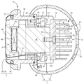
(実施例) 図1ないし図9は本発明に係る美容器具の第1実施例を示す。本発明における前後・左右・上下とは、図2および図3に示す交差矢印と、矢印の近傍に表示した前後・左右・上下の表記に従う。図2および図3において美容器具は、グリップを兼ねる本体ケース1を基本構造体にして、その前面上部にヘッド2が突設してある。またその内部には、ヘッド2を冷却するための熱電変換素子44を含む冷却部12と、冷却部12に接続される放熱用のヒートシンク30と、ヒートシンク30に熱交換風を供給する送風手段31とを備えている。ヒートシンク30は、アルミニウム製のダイキャスト成形品からなり、その表面にアルマイト処理を施し放熱効果を高めている。 (Example) FIG. 1 thru | or FIG. 9 shows 1st Example of the beauty instruments based on this invention. In the present invention, “front / rear / left / right / upper / lower” follows the crossing arrows shown in FIGS. 2 and 3, the beauty tool has a main body case 1 that also serves as a grip as a basic structure, and a head 2 projects from the upper part of the front surface thereof. Further, in the interior thereof, a cooling unit 12 including a thermoelectric conversion element 44 for cooling the head 2, a heat sink 30 for heat dissipation connected to the cooling unit 12, and a blower unit 31 for supplying heat exchange air to the heat sink 30. And. The heat sink 30 is made of an aluminum die-cast product, and an alumite treatment is applied to the surface to enhance the heat dissipation effect.

本体ケース1の前面には、電源投入用の電源ボタン(スイッチ)3と、運転モードを切り換えるモードボタン(スイッチ)4と、イオン導入時の電位を切り換える強弱ボタン(スイッチ)5と、運転モードの違いに応じて点灯される4個のLEDからなるモード表示灯(発光表示手段)6a、6b、6c、6dと、電位の違いに応じて点灯される2個のLEDからなる強弱表示灯(発光表示手段)7a、7bなどが設けてある。電源ボタン3は、本体ケース1の表面にある電源操作ノブ3aとその奥にある電源スイッチ3bとからなる。モードボタン4は、本体ケース1の表面にあるモード操作ノブ4aとその奥にあるモードスイッチ4bとからなる。強弱ボタン5は、本体ケース1の表面にある強弱操作ノブ5aとその奥にある強弱スイッチ5bとからなる。   On the front surface of the main body case 1 are a power button (switch) 3 for turning on the power, a mode button (switch) 4 for switching the operation mode, a strength button (switch) 5 for switching the potential at the time of ion introduction, and an operation mode. Mode indicator lamps (light emitting display means) 6a, 6b, 6c, 6d that are turned on according to the difference, and strength indicator lamps (light emission) made up of two LEDs that are turned on according to the potential difference Display means) 7a, 7b, etc. are provided. The power button 3 includes a power operation knob 3a on the surface of the main body case 1 and a power switch 3b in the back. The mode button 4 includes a mode operation knob 4a on the surface of the main body case 1 and a mode switch 4b in the back thereof. The strength button 5 includes a strength control knob 5a on the surface of the main body case 1 and a strength switch 5b in the back thereof.

本体ケース1の左右両側には、上下端が半楕円状に丸められた縦長の第2電極10が配置してある。第2電極10は、人体に微弱なパルス電流を供給するイオン導入またはイオン導出用の電極であって、第1電極9を兼ねる接触板39と協同してパルス電流を人体に供給する。第2電極10は、本体ケース1に対して固定されており、後述する圧縮コイル形のばね94を介して、イオン導入またはイオン導出用の制御回路87の出力リード90と電気的に接続されている(図9参照)。   On the left and right sides of the main body case 1, vertically long second electrodes 10 whose upper and lower ends are rounded into a semi-elliptical shape are arranged. The second electrode 10 is an electrode for ion introduction or ion derivation that supplies a weak pulse current to the human body, and supplies the pulse current to the human body in cooperation with the contact plate 39 that also serves as the first electrode 9. The second electrode 10 is fixed to the main body case 1 and is electrically connected to the output lead 90 of the control circuit 87 for ion introduction or ion derivation via a compression coil spring 94 described later. (See FIG. 9).

本体ケース1は、前後に分割された前ケース1aと後ケース1bをビス8(図1参照)で蓋合わせ状に接合して中空ケース状に構成してあり、その内部には、冷却部12の一部が収容される通風エリア13と、マイコンや各種電子部品を含む制御回路87や、それを搭載する回路基板14が配置される電気部品エリア15とが区画してある。具体的には、前ケース1aの内面に周回状に突設される区画リブ17と、区画リブ17の開口面を塞ぐカバー体18とで電気部品エリア15を区画し、電気部品エリア15以外の本体ケース1の内部空間の主に後半部側を通風エリア13としている。つまり、本体ケース1の壁とカバー体18の壁により、通風エリア13と電気部品エリア15とが区分してある。制御回路87は、冷却部12のペルチェ素子(熱電変換素子)44、バイブレータ33(モーター82)、送風手段31(モーター66)、ブザー(発音表示手段)95、モード表示灯(発光表示手段)6a、6b、6c、6d、強弱表示灯(発光表示手段)7a、7bの駆動、および第1電極9・第2電極10への微弱なパルス電流の供給(通電)を制御している。   The main body case 1 is formed in a hollow case shape by joining a front case 1a and a rear case 1b, which are divided into front and rear, with a screw 8 (see FIG. 1) in a lid-like shape. Is divided into a ventilation area 13 in which a part thereof is accommodated, a control circuit 87 including a microcomputer and various electronic components, and an electrical component area 15 in which a circuit board 14 on which the circuit is mounted. Specifically, the electrical component area 15 is partitioned by a partition rib 17 projecting in a circular manner on the inner surface of the front case 1 a and a cover body 18 that closes the opening surface of the partition rib 17. A ventilation area 13 is mainly used in the rear half of the internal space of the main body case 1. That is, the ventilation area 13 and the electrical component area 15 are divided by the wall of the main body case 1 and the wall of the cover body 18. The control circuit 87 includes a Peltier element (thermoelectric conversion element) 44, a vibrator 33 (motor 82), a blower means 31 (motor 66), a buzzer (sound generation display means) 95, and a mode indicator (light emission display means) 6a. , 6b, 6c, 6d, driving of the strength indicator lamps (light emitting display means) 7a, 7b, and supply (energization) of weak pulse current to the first electrode 9 and the second electrode 10 are controlled.

カバー体18は、トレー状のプラスチック成形品からなり、区画リブ17に接合される周囲壁19と、周囲壁19の後面を塞ぐ後壁20を一体に備えている。周囲壁19の上端には、締結座21が張り出してあり、その左右中央部分にバイブレータ33を固定する押圧壁22が一体に形成してある(図9参照)。図5に示すように、後壁20の下部には、ファンケース65の周面の一部を収容する長円状の凹部23が凹み形成してあり、その左右両側にファンケース65を固定するためのねじボス24が突設してある。カバー体18の区画リブ17との接合面はシールリング25でシールしてある。押圧壁22は長方形状に張り出してあり、バイブレータ33用のモーター82の周面全体を覆う状態で、同モーター82を押圧固定する(図9参照)。   The cover body 18 is made of a tray-shaped plastic molded product, and integrally includes a peripheral wall 19 joined to the partition rib 17 and a rear wall 20 that closes the rear surface of the peripheral wall 19. A fastening seat 21 protrudes from the upper end of the peripheral wall 19, and a pressing wall 22 for fixing the vibrator 33 is formed integrally with the left and right central portions (see FIG. 9). As shown in FIG. 5, an oval recess 23 that accommodates a part of the peripheral surface of the fan case 65 is formed in the lower portion of the rear wall 20, and the fan case 65 is fixed to both the left and right sides thereof. A screw boss 24 for projecting is provided. The joint surface of the cover body 18 with the partition rib 17 is sealed with a seal ring 25. The pressing wall 22 protrudes in a rectangular shape, and presses and fixes the motor 82 in a state of covering the entire peripheral surface of the motor 82 for the vibrator 33 (see FIG. 9).

通風エリア13の上部には冷却部12が設けてあり、さらに、冷却部12の後端に接続した放熱用のヒートシンク30と、送風手段31と、変向体32とが、通風エリア13内に上下に間隔をあけた状態で記載順に配置してある。これにより本体ケース1の上部構造が占める空間量を小さくして、本体ケース1のグリップ部分をスリム化できる。また、冷却部12と電気部品エリア15との間の前ケース1aの内部に、美容器具の全体を振動させるためのバイブレータ33が配置してある。   A cooling unit 12 is provided above the ventilation area 13, and a heat sink 30 for heat dissipation, a blower unit 31, and a diverter 32 connected to the rear end of the cooling unit 12 are provided in the ventilation area 13. They are arranged in the order of description with a space in the vertical direction. Thereby, the amount of space occupied by the upper structure of the main body case 1 can be reduced, and the grip portion of the main body case 1 can be slimmed. In addition, a vibrator 33 for vibrating the entire beauty tool is disposed inside the front case 1a between the cooling unit 12 and the electrical component area 15.

冷却部12は、ヘッド2と接触して、ヘッド2の表面を冷却する冷却ユニット37を含んで構成する。円筒状のヘッドケース36は、前ケース1aの内面にビス35で固定されて前ケース1aより前方へ突出しており、その突端にヘッド2が固定してある。これらヘッド2、ヘッドケース36、本体ケース1で囲まれる空間内に冷却部12は収容されている。なお、ヘッドケース36は特に必要はなく、ヘッド2が直接本体ケース1から突出する構成であってもよい。その場合、冷却部12のほとんどが本体ケース1内に収容される。また、ヘッドケース36は、本体ケース1とは別の名称としているが、本体ケース1の一部としてみることもできる。ヘッド2は、チタン板を皿状に成形した接触板39と、接触板39の周縁部分を固定保持する保持リング40とからなる。図6に示すように、保持リング40は、ヘッドケース36の突端外面に外嵌装着されてビス41で固定してある。ヘッドケース36と前ケース1aとの間、および接触板39とヘッドケース36との間は、それぞれシールリング26・27でシールしてある。接触板39はチタンに限らず、電流を流せて熱伝導がよければアルミニウムなどの他の金属であってもよい。   The cooling unit 12 includes a cooling unit 37 that contacts the head 2 and cools the surface of the head 2. The cylindrical head case 36 is fixed to the inner surface of the front case 1a with screws 35 and protrudes forward from the front case 1a. The head 2 is fixed to the protruding end. The cooling unit 12 is accommodated in a space surrounded by the head 2, the head case 36, and the main body case 1. The head case 36 is not particularly required, and may be configured such that the head 2 projects directly from the main body case 1. In that case, most of the cooling unit 12 is accommodated in the main body case 1. The head case 36 has a name different from that of the main body case 1, but can also be seen as a part of the main body case 1. The head 2 includes a contact plate 39 in which a titanium plate is formed in a dish shape, and a holding ring 40 that fixes and holds the peripheral portion of the contact plate 39. As shown in FIG. 6, the holding ring 40 is fitted on the outer surface of the protruding end of the head case 36 and fixed with screws 41. Sealing between the head case 36 and the front case 1a and between the contact plate 39 and the head case 36 are performed by seal rings 26 and 27, respectively. The contact plate 39 is not limited to titanium, but may be other metal such as aluminum as long as current can be passed and heat conduction is good.

冷却ユニット37は、ペルチェ素子(熱電変換素子)44と、同素子44を間に挟んで低温面側と高温面側に密着される冷熱ブロック45および温熱ブロック46と、これら三者44・45・46を支持する冷却部ホルダー47などで構成する。冷熱ブロック45および温熱ブロック46とペルチェ素子44とは伝熱シート48を介して密着してある。伝熱シート48は、アルミニウムシートの表裏のそれぞれにシリコンをコーティングして構成してある。ペルチェ素子(熱電変換素子)44と、冷熱ブロック45と、温熱ブロック46とは、冷却部ホルダー47に挿通したビス49で、両ブロック45・46の間に配置した熱絶縁体50と共に締結されてユニット部品化してある(図5参照)。   The cooling unit 37 includes a Peltier element (thermoelectric conversion element) 44, a cooling block 45 and a heating block 46 that are in close contact with the low temperature side and the high temperature side with the element 44 interposed therebetween, and these three units 44, 45, The cooling unit holder 47 that supports the cooling unit 46 is used. The cooling block 45 and the heating block 46 are in close contact with the Peltier element 44 via a heat transfer sheet 48. The heat transfer sheet 48 is configured by coating silicon on both the front and back surfaces of an aluminum sheet. The Peltier element (thermoelectric conversion element) 44, the cooling block 45, and the heating block 46 are fastened together with the thermal insulator 50 disposed between the blocks 45 and 46 by screws 49 inserted into the cooling unit holder 47. It is unitized (see FIG. 5).

冷却部ホルダー47を、図9に示すように前ケース1aに4個のビス51で固定することにより、冷熱ブロック45の前端面が接触板39の内面に密着する状態で、冷却ユニット37が前ケース1aおよびヘッドケース36に固定してある。この状態の温熱ブロック46の後端は、前後ケース1a・1bの接合面より後ケース1b側へ入り込んでいる(図6参照)。   As shown in FIG. 9, the cooling unit holder 47 is fixed to the front case 1a with four screws 51 so that the front end surface of the cooling block 45 is in close contact with the inner surface of the contact plate 39 so that the cooling unit 37 can be It is fixed to the case 1a and the head case 36. The rear end of the thermal block 46 in this state enters the rear case 1b side from the joint surface of the front and rear cases 1a and 1b (see FIG. 6).

冷熱ブロック45および温熱ブロック46は、それぞれアルミニウム製のダイキャスト成形品からなる。ペルチェ素子(熱電変換素子)44で発生した熱の放出をより効果的に行うために、温熱ブロック46の体積(質量)を冷熱ブロック45の体積(質量)に比べて十分に大きくして、単位時間当たりの熱伝導量(熱容量)を大きくしている。これにより、ペルチェ素子44の高温面側で発生する熱を、温熱ブロック46の後端に固定したヒートシンク30へ効果的に伝導して放熱作用を促進できる。一方で、温熱ブロック46の表面積を冷熱ブロック45の表面積に比べて十分に大きくして、温熱ブロック46における単位時間当たりの放熱量を大きくしている。また、ヒートシンク30の体積(質量)を温熱ブロック46の体積(質量)に比べて大きくして、単位時間当たりの熱伝導量(熱容量)を大きくしている。これにより、ペルチェ素子(熱電変換素子)44の高温面側で発生する熱を、温熱ブロック46およびヒートシンク30の両者の熱容量によって、蓄えることができるので、送風手段31の駆動を意図的に停止することができる。或いは、熱容量が少なければ、送風手段31用のモーター66が不用意に止まった場合に、ペルチェ素子(熱電変換素子)44の低温面側が熱くなり、それに伴い接触板39が熱くなって使用者に不快な思いをさせる場合があったが、それを防止することができる。さらに、ヒートシンク30の表面積を温熱ブロック46の表面積よりも大きくしていることにより、より一層放熱効果が高い。温熱ブロック46とヒートシンク30は一体のアルミダイキャスト成形品であってもよい。放熱効率を向上させるため温熱ブロック46の周囲に複数のフィンを設けることもできる。   The cooling block 45 and the heating block 46 are each made of an aluminum die-cast molded product. In order to more effectively release the heat generated in the Peltier element (thermoelectric conversion element) 44, the volume (mass) of the heating block 46 is made sufficiently larger than the volume (mass) of the cooling block 45, and the unit The amount of heat conduction per hour (heat capacity) is increased. Thereby, the heat generated on the high temperature surface side of the Peltier element 44 can be effectively conducted to the heat sink 30 fixed to the rear end of the thermal block 46 to promote the heat radiation action. On the other hand, the surface area of the heat block 46 is made sufficiently larger than the surface area of the heat block 45 to increase the heat radiation amount per unit time in the heat block 46. In addition, the volume (mass) of the heat sink 30 is made larger than the volume (mass) of the thermal block 46 to increase the heat conduction amount (heat capacity) per unit time. Thereby, the heat generated on the high temperature surface side of the Peltier element (thermoelectric conversion element) 44 can be stored by the heat capacities of both the heat block 46 and the heat sink 30, so that the driving of the blowing means 31 is intentionally stopped. be able to. Alternatively, if the heat capacity is small, when the motor 66 for the air blowing means 31 is stopped carelessly, the low temperature surface side of the Peltier element (thermoelectric conversion element) 44 becomes hot, and the contact plate 39 becomes hot accordingly. There are times when it makes me feel uncomfortable, but it can be prevented. Furthermore, since the surface area of the heat sink 30 is larger than the surface area of the thermal block 46, the heat dissipation effect is further enhanced. The heat block 46 and the heat sink 30 may be an integral aluminum die cast product. In order to improve the heat dissipation efficiency, a plurality of fins can be provided around the thermal block 46.

図5および図6に示すように、ヒートシンク30は、板状のシンクベース54と、シンクベース54の後面に突設される多数個のフィン55とを一体に備えたアルミニウム製のダイキャスト成形品からなる。ヒートシンク30は、シンクベース54の上部を温熱ブロック46に相対移動不能に係合した接触状態で、温熱ブロック46にねじ込まれるビス56で分離不能に締結してある。シンクベース54の上下中途部には斜め下向きに傾斜する段違い部57が形成してあり、したがって、段違い部57より下側の板状部54bは、段違い部57より上側の板状部54aよりも後ケース1bに接近している。冷却部12とヒートシンク30との接続は、温熱ブロック46に対してシンクベース54を直接固定する上記構造に限らず、温熱ブロック46とシンクベース54の向き合う面が接触した状態のままで、ヒートシンク30を前ケース1aに締結する固定構造とすることができる。   As shown in FIGS. 5 and 6, the heat sink 30 is an aluminum die-cast molded product integrally including a plate-shaped sink base 54 and a large number of fins 55 protruding from the rear surface of the sink base 54. Consists of. The heat sink 30 is fastened so as not to be separated by screws 56 screwed into the heat block 46 in a contact state where the upper part of the sink base 54 is engaged with the heat block 46 so as not to be relatively movable. A stepped portion 57 that is inclined obliquely downward is formed in the upper and lower middle portion of the sink base 54. Therefore, the plate-like portion 54b below the stepped portion 57 is higher than the plate-like portion 54a above the stepped portion 57. It is approaching the rear case 1b. The connection between the cooling unit 12 and the heat sink 30 is not limited to the above-described structure in which the sink base 54 is directly fixed to the thermal block 46, and the heat sink 30 is kept in a state where the facing surfaces of the thermal block 46 and the sink base 54 are in contact with each other. Can be fixed to the front case 1a.

フィン55と冷却風との接触機会を増加して熱交換効率を高めるために、ヒートシンク30は通風エリア13に沿って縦長に形成してある。さらに、シンクベース54と、同ベース54に対向する後ケース1bの周壁とで挟まれる熱交換通路60の通路断面積を、ヒートシンク30の側から送風手段31の側へ向かって小さくなるようにしている。より具体的には、シンクベース54と対向する後ケース1bの周壁を、シンクベース54に接近する向きに凹ませて、熱交換通路60の通路断面積を、シンクベース54の上端側から下端側へ向かって下すぼまり状に形成している。因みに、シンクベース54の下端側と後ケース1bの周壁との対向間隔を、シンクベース54の上端側と後ケース1bの周壁との対向間隔より小さくして、熱交換通路60の通路断面積を、送風手段31の側へ向かって下すぼまり状に形成することができる。   In order to increase the chance of contact between the fins 55 and the cooling air and increase the heat exchange efficiency, the heat sink 30 is formed vertically along the ventilation area 13. Further, the passage cross-sectional area of the heat exchange passage 60 sandwiched between the sink base 54 and the peripheral wall of the rear case 1b facing the base 54 is made smaller from the heat sink 30 side toward the air blowing means 31 side. Yes. More specifically, the peripheral wall of the rear case 1 b facing the sink base 54 is recessed so as to approach the sink base 54, and the passage cross-sectional area of the heat exchange passage 60 is changed from the upper end side to the lower end side of the sink base 54. It is formed in a constricted shape downward. Incidentally, the distance between the lower end side of the sink base 54 and the peripheral wall of the rear case 1b is made smaller than the distance between the upper end side of the sink base 54 and the peripheral wall of the rear case 1b, so that the passage sectional area of the heat exchange passage 60 is increased. It can be formed in a constricted shape toward the blowing means 31 side.

上記のように、ヒートシンク30の上下長を大きくすることにより、フィン55による放熱量を増強できる。さらに、熱交換通路60を下すぼまり状に形成することにより、フィン55の間を通過する冷却風の通過速度を大きくして、フィン55と冷却空気との接触機会を増加でき、全体としてヒートシンク30の熱交換効率を高めることができる。ヒートシンク30を、冷却部12からカバー体18の外面にわたって縦長に配置するので、下側の板状部54bの過半下部はカバー体18の後面上部の外方を覆っている(図1、図6参照)。そのため、吸込み口61から浸入した化粧水をシンクベース54で遮蔽して、化粧水がカバー体18に付着するのをよく防止できる。また、シンクベース54の上下中途部に段違い部57を設けておくことにより、上側の板状部54aに沿って流下する化粧水を段違い部57で受け止めて、そこに滞留させることができる。   As described above, the amount of heat released by the fins 55 can be increased by increasing the vertical length of the heat sink 30. Furthermore, by forming the heat exchange passage 60 in a constricted shape, the passage speed of the cooling air passing between the fins 55 can be increased, and the chance of contact between the fins 55 and the cooling air can be increased. The heat exchange efficiency of 30 can be increased. Since the heat sink 30 is arranged vertically from the cooling unit 12 to the outer surface of the cover body 18, the majority lower part of the lower plate-like part 54b covers the outside of the upper rear surface of the cover body 18 (FIGS. 1 and 6). reference). Therefore, the lotion that has entered through the suction port 61 is shielded by the sink base 54, and the lotion can be well prevented from adhering to the cover body 18. Further, by providing the stepped portion 57 in the middle part of the sink base 54, the lotion flowing down along the upper plate-like portion 54a can be received by the stepped portion 57 and retained therein.

シンクベース54の上側の板状部54aと対向する後ケース1bの周壁には、冷却空気用の吸込み口61の一群が開口してある。また、後ケース1bの下部側の周壁には、熱交換後の温風を排出する一群の排出口62が開口してある。このように、本体ケース1の下部側から温風を排出する構造を採用すると、冷却対象の肌から遠ざかった位置で温風を排出できるので、ユーザーに不快感を与えることがない。本実施例では吸込み口61、排出口62が側方(後方)に向けて開口しているが、それに限らず吸込み口61が上方に向けて開口し、排出口62が下方に向けて開口するものであってもよい。   A group of cooling air suction ports 61 are opened in the peripheral wall of the rear case 1 b facing the upper plate-like portion 54 a of the sink base 54. Further, a group of discharge ports 62 for discharging the warm air after heat exchange is opened in the peripheral wall on the lower side of the rear case 1b. Thus, if the structure which discharges warm air from the lower part side of main body case 1 is employ | adopted, since warm air can be discharged in the position away from the skin of cooling object, it does not give a user discomfort. In the present embodiment, the suction port 61 and the discharge port 62 are opened toward the side (rear), but the suction port 61 is opened upward and the discharge port 62 is opened downward. It may be a thing.

先に説明した下側の板状部54bとカバー体18との間には、熱交換通路60の前後隙間より小さな通風隙間63が確保してあり、したがって通風エリア13内の冷却風の一部は通風隙間63を経由して送風手段31に吸い込まれる。このように、通風隙間63を確保しておくことにより、シンクベース54の熱がカバー体18へ伝導するのを防止できる。また、通風隙間63の隙間寸法が小さいので、送風手段31に吸い込まれる冷却風の殆どを熱交換通路60に沿って流動させて、熱交換を効果的に行なうことができる。   Between the lower plate-like portion 54b described above and the cover body 18, a ventilation gap 63 smaller than the front and rear gaps of the heat exchange passage 60 is secured, and therefore a part of the cooling air in the ventilation area 13 is secured. Is sucked into the blowing means 31 through the ventilation gap 63. Thus, by ensuring the ventilation gap 63, it is possible to prevent the heat of the sink base 54 from being conducted to the cover body 18. In addition, since the gap size of the ventilation gap 63 is small, most of the cooling air sucked into the blower unit 31 can flow along the heat exchange passage 60 to effectively perform heat exchange.

送風手段31は、モーターホルダーを兼ねるファンケース65と、ファンケース65の上半部に固定されるモーター66と、その出力軸に固定される軸流型のファン67とで構成してある。ファン67の回転・停止は、制御回路87からモーター66への駆動電流を制御してモーター66の出力を切り替えることで行っている。送風手段31は、軸流型のファンに限らず、遠心型のファンであってもよい。また、送風手段31は、放電電極と対向電極とを設け、両者に高電圧を印加してイオン風を発生させるものであってもよい。この場合、送風力は小さいが音はほとんど発生しない。通風エリア13内の空気を変向体32へ向かって下向きに送給する。ファンケース65は、先に説明したねじボス24にビス71で固定してある(図9参照)。なお、ファンケース65の周囲は、カバー体18と後ケース1bから対向状に張り出した区分壁72で上下に区分してあり(図7参照)、したがって、送風手段31から送出された熱交換後の温風が熱交換通路60側へ逆流することはない。   The air blowing means 31 includes a fan case 65 that also serves as a motor holder, a motor 66 that is fixed to the upper half of the fan case 65, and an axial-flow fan 67 that is fixed to the output shaft thereof. The fan 67 is rotated and stopped by controlling the drive current from the control circuit 87 to the motor 66 and switching the output of the motor 66. The air blowing means 31 is not limited to the axial flow type fan, but may be a centrifugal type fan. Moreover, the ventilation means 31 may provide a discharge electrode and a counter electrode, and may generate an ion wind by applying a high voltage to both. In this case, the blowing power is small, but almost no sound is generated. The air in the ventilation area 13 is sent downward toward the deflector 32. The fan case 65 is fixed to the screw boss 24 described above with screws 71 (see FIG. 9). The periphery of the fan case 65 is vertically divided by a partition wall 72 projecting from the cover body 18 and the rear case 1b so as to face each other (see FIG. 7). Therefore, after the heat exchange sent from the blowing means 31 is completed. Does not flow back to the heat exchange passage 60 side.

図5に示すように、変向体32は、前面および下面が開口するカバー状の構造体からなり、後面側から見た外形形状は逆凸字状に形成してある(図9参照)。図7に示すように排出口62と対向する変向体32の上半側の幅広の部分には、変向壁68が下り傾斜状に形成してある。また、変向壁68の上端の傾斜部内面には、接当リブ69が設けてある。先に述べた凹部23の下端には、部分球面状の変向面70が形成してあり、この変向面70によって送風手段31から送給される熱交換風を、変向壁68と共同して排出口62へ向かって変向案内できる。上記実施例では、本体ケース1の上部に吸込み口61を、本体ケース1の下部に排出口62を形成して、通風エリア13内の熱交換(冷却)風を下向きに送給したが、本体ケース1の上部に排出口62を、本体ケース1の下部に吸込み口61を形成して、通風エリア13内の熱交換(冷却)風を上向きに送給してもよい。当然その場合の送風手段31の送風方向は逆に設定する。   As shown in FIG. 5, the deflecting body 32 is formed of a cover-like structure whose front and bottom surfaces are open, and the outer shape viewed from the rear side is formed in an inverted convex shape (see FIG. 9). As shown in FIG. 7, a turning wall 68 is formed in a downwardly inclined manner in the wide portion on the upper half side of the turning body 32 facing the discharge port 62. A contact rib 69 is provided on the inner surface of the inclined portion at the upper end of the turning wall 68. A partially spherical turning surface 70 is formed at the lower end of the recess 23 described above, and heat exchange air supplied from the blowing means 31 by this turning surface 70 is shared with the turning wall 68. Then, it is possible to guide the direction of change toward the outlet 62. In the above embodiment, the suction port 61 is formed in the upper portion of the main body case 1 and the discharge port 62 is formed in the lower portion of the main body case 1 so that the heat exchange (cooling) air in the ventilation area 13 is sent downward. A discharge port 62 may be formed in the upper part of the case 1 and a suction port 61 may be formed in the lower part of the main body case 1 so that heat exchange (cooling) air in the ventilation area 13 may be supplied upward. Of course, the blowing direction of the blowing means 31 in that case is set in reverse.

前後ケース1a・1bの下端内面には給電用のソケット75が配置してあり、その通風エリア13側の周面が変向体32で覆ってある。変向体32およびソケット75は、前後ケース1a・1bを締結する下側2個のビス8を利用して固定されて、本体ケース1と一体化してある。図7に示すように、給電用のソケット75の内部には、電源アダプターから導出された給電プラグ74を接続するための2個の接続ピン76が設けてあり、接続ピン76に接続した給電リード77がソケット75の上端から導出してある。給電リード77は、カバー体18に開口したリード開口78を介して電気部品エリア15の内部に導入されて回路基板14に接続してある。給電リード77とリード開口78との間の隙間は、リード開口78に装着したゴム製のパッキン79で封止してある。   A power feeding socket 75 is arranged on the inner surfaces of the lower ends of the front and rear cases 1a and 1b, and the circumferential surface on the side of the ventilation area 13 is covered with a deflecting body 32. The diverter 32 and the socket 75 are fixed to each other by using the lower two screws 8 that fasten the front and rear cases 1a and 1b, and are integrated with the main body case 1. As shown in FIG. 7, two connection pins 76 for connecting a power supply plug 74 led out from the power adapter are provided in the power supply socket 75, and the power supply leads connected to the connection pins 76 are provided. 77 is derived from the upper end of the socket 75. The power supply lead 77 is introduced into the electrical component area 15 through a lead opening 78 opened in the cover body 18 and connected to the circuit board 14. A gap between the power supply lead 77 and the lead opening 78 is sealed with a rubber packing 79 attached to the lead opening 78.

先に説明したように変向体32は、本体ケース1に固定してある。そのため、送風手段31の振動や、バイブレータ33の振動を受けて振動し、その上開口縁がカバー体18に接当して、接当騒音を生じるおそれがある。こうした騒音の発生を防ぐために、変向体32の接当リブ69の突端をパッキン79の後端面で受け止めて、変向体32がカバー体18に接当するのを防止し、変向体32の振動をパッキン79で吸収できるようにしている(図7の拡大図参照)。   As described above, the deflector 32 is fixed to the main body case 1. Therefore, it vibrates in response to the vibration of the blowing means 31 and the vibration of the vibrator 33, and the upper opening edge may contact the cover body 18 to generate contact noise. In order to prevent the generation of such noise, the projecting end of the contact rib 69 of the deflector 32 is received by the rear end surface of the packing 79 to prevent the deflector 32 from coming into contact with the cover body 18. Can be absorbed by the packing 79 (see the enlarged view of FIG. 7).

前ケース1aの内部に配置したバイブレータ33は、モーター82と、その出力軸に固定される偏心重り83とで構成し、モーター82の回転駆動により振動を発生する。バイブレータ33は、後述するように振動により器具の状態を表示できる振動表示手段を兼ねている。前ケース1aの内部にはゴム製の装着座84が固定してあり、この装着座84に嵌め込んだモーター82をカバー体18に設けた押圧壁22で分離不能に固定保持している(図6参照)。   The vibrator 33 arranged inside the front case 1a is composed of a motor 82 and an eccentric weight 83 fixed to the output shaft thereof, and generates vibration by the rotational drive of the motor 82. The vibrator 33 also serves as vibration display means that can display the state of the appliance by vibration as will be described later. A rubber mounting seat 84 is fixed inside the front case 1a, and the motor 82 fitted in the mounting seat 84 is fixed and held by the pressing wall 22 provided on the cover body 18 so as not to be separated (see FIG. 6).

上述したように、電気部品エリア15には次のような部材が収容してある。ペルチェ素子(熱電変換素子)44への通電(駆動)状態と、バイブレータ(振動表示手段)33のモーター82への通電(駆動)状態と、ファン67用のモーター66(送風手段31)への通電(駆動)状態と、発音表示手段としてのブザー95への通電(駆動)状態と、モード表示灯(発光表示手段)6a、6b、6c、6dへの通電(駆動)状態と、強弱表示灯(発光表示手段)7a、7bへの通電(駆動)状態、および第1電極9・第2電極10への通電(駆動)状態を制御する制御回路87や制御回路87に命令信号を送出する各種スイッチ3b・4b・5bやそれらを搭載する回路基板14などが収容されている。制御回路87に接続される一方の出力リード89は、図8に示すようにヘッドケース36の内部に設けた弾性変形可能な接触部93を一体に備えた接続端子91に接続されており、他方の出力リード90は、図9に示すようにファンケース65の左右に固定した接続端子92に接続してある。前者の接続端子91は金属板材からなり、ヘッドケース36を前ケース1aに締結するビス35を利用してその自由端側、つまり接触部93側が弾性変形可能に固定してある。   As described above, the following components are accommodated in the electrical component area 15. The energization (drive) state of the Peltier element (thermoelectric conversion element) 44, the energization (drive) state of the vibrator (vibration display means) 33 to the motor 82, and the energization of the motor 66 (blower means 31) for the fan 67 (Driving) state, energizing (driving) state to the buzzer 95 as a sound generation display means, energizing (driving) states to the mode indicator lamps (light emitting display means) 6a, 6b, 6c, 6d, and the strength indicator lamp ( Various switches for sending command signals to the control circuit 87 and the control circuit 87 for controlling the energization (drive) state of the light emitting display means) 7a and 7b and the energization (drive) state of the first electrode 9 and the second electrode 10 3b, 4b, 5b, a circuit board 14 on which they are mounted, and the like are accommodated. One output lead 89 connected to the control circuit 87 is connected to a connection terminal 91 integrally provided with an elastically deformable contact portion 93 provided inside the head case 36 as shown in FIG. The output leads 90 are connected to connection terminals 92 fixed to the left and right sides of the fan case 65 as shown in FIG. The former connection terminal 91 is made of a metal plate, and its free end side, that is, the contact portion 93 side is fixed to be elastically deformable by using a screw 35 for fastening the head case 36 to the front case 1a.

ヘッド2をヘッドケース36に組み付けた状態では、接続端子91の腕部の先端側に設けた接触部93が、第1電極9を兼ねる接触板39の内面に押圧された状態で密着している。このように、弾性変形可能な接触部93を介して接続端子91と第1電極9を導通すると、接続端子91の固定部分と第1電極9との間に寸法誤差が生じていたとしても、寸法誤差を接続端子91の腕部で吸収して、電気的な接続状態を良好に維持できる。とくに、美容器具の使用時には、ヘッド2が冷却され、あるいは常温に戻るため、温度変化に伴う各部品間の距離の変化を生じやすいが、こうした場合であっても電気的な接続状態を良好に維持できる。   In a state in which the head 2 is assembled to the head case 36, the contact portion 93 provided on the distal end side of the arm portion of the connection terminal 91 is in close contact with the inner surface of the contact plate 39 that also serves as the first electrode 9. . As described above, when the connection terminal 91 and the first electrode 9 are conducted through the elastically deformable contact portion 93, even if a dimensional error occurs between the fixed portion of the connection terminal 91 and the first electrode 9, A dimension error is absorbed by the arm part of the connection terminal 91, and an electrical connection state can be maintained favorable. In particular, when using a beauty tool, the head 2 is cooled or returned to room temperature, so the distance between the components is likely to change due to the temperature change. Even in such a case, the electrical connection state is good. Can be maintained.

また、第2電極10用の接続端子92は、ファンケース65を固定するビス71を利用して固定してあり、第2電極10と接続端子92とは、第2電極10を押圧付勢するばね94を利用して導通してある。接続端子92と第2電極10とをコイル状のばね(弾性体)94を介して導通すると、接続端子92と第2電極10との間に寸法誤差が生じたとしても、寸法誤差をばね94で吸収できるので、良好な電気的接続状態を維持できる。   The connection terminal 92 for the second electrode 10 is fixed using a screw 71 for fixing the fan case 65, and the second electrode 10 and the connection terminal 92 press and urge the second electrode 10. The spring 94 is used for conduction. When the connection terminal 92 and the second electrode 10 are conducted through a coiled spring (elastic body) 94, even if a dimensional error occurs between the connection terminal 92 and the second electrode 10, the dimensional error is reduced by the spring 94. Therefore, it is possible to maintain a good electrical connection state.

接続端子91は、金属線材の基端部分をL字状に折り曲げて固定部とし、他方端を、コイル状に形成してばね性を備えた接触部93とすることができる。その場合には、固定部をビス35で固定し、自由端側の接触部93を第1電極9に押圧した状態で組み付け、接続端子91と第1電極9とを導通させる。この構造の場合にも、接続端子91の固定部分と第1電極9との間に寸法誤差が生じたとしても弾性接触によって良好な電気的接続状態を維持できる。   The connection terminal 91 can be formed as a fixed portion by bending the base end portion of the metal wire into an L shape, and the other end can be formed as a coil-shaped contact portion 93 having spring properties. In that case, the fixing part is fixed with the screw 35, the contact part 93 on the free end side is assembled to the first electrode 9 in a pressed state, and the connection terminal 91 and the first electrode 9 are made conductive. Even in the case of this structure, even if a dimensional error occurs between the fixed portion of the connection terminal 91 and the first electrode 9, a good electrical connection state can be maintained by elastic contact.

図9において、符号101はペルチェ素子(熱電変換素子)44用の給電リード、符号102は送風手段31用の給電リード、符号103はバイブレータ33用の給電リードである。これらの各給電リード101・102・103のリード開口や、先に説明した出力リード89・90のリード開口も、給電リード77と同様にしてパッキンでシールしてある。   In FIG. 9, reference numeral 101 denotes a power supply lead for the Peltier element (thermoelectric conversion element) 44, reference numeral 102 denotes a power supply lead for the blowing means 31, and reference numeral 103 denotes a power supply lead for the vibrator 33. The lead openings of each of the power supply leads 101, 102, and 103 and the lead openings of the output leads 89 and 90 described above are sealed with packing in the same manner as the power supply lead 77.

以上のように構成した美容器具は、電源ボタン3がオン操作されると、制御回路87から駆動電流が供給されて、バイブレータ33のモーター82が起動され、所定時間(例えば1秒間)後、下記の第1モードとなり器具が待機状態となる。電源ボタン3がオン操作されたときバイブレータ33が駆動することにより、手の感触で器具が起動していることを確認できるので、ユーザーの安心感につながる。   In the beauty device configured as described above, when the power button 3 is turned on, a driving current is supplied from the control circuit 87, the motor 82 of the vibrator 33 is activated, and after a predetermined time (for example, 1 second), The first mode is entered, and the instrument enters a standby state. Since the vibrator 33 is driven when the power button 3 is turned on, it can be confirmed that the instrument is activated by the touch of the hand, which leads to a sense of security for the user.

モードボタン4は、オン操作するごとに第1モードから第4モードまで切り換えることができる。また、モードボタン4をオン操作するごとに「ピッ」「ピッ」とブザー95の音を鳴らすよう制御している。第1モード(クレンジングモード)では、第1電極9をプラス極性、第2電極10をマイナス極性とした電圧が印加される。これにより化粧水が含浸された化粧用の綿マット97(図3参照)を接触板39の外面にあてがい、その周囲をヘッド2に圧嵌装着されるキャップ98で固定した状態で、第2電極10を含む本体ケース1を手で握り、綿マット97(第1電極9)を顔などの肌にあてがえばイオン導出を行うことができ、肌の微細な汚れを落とすことができる。制御回路87は、モード表示灯(発光表示手段)6aにも通電し、モード表示灯6aを点滅、点灯或いは消灯を制御する。   The mode button 4 can be switched from the first mode to the fourth mode every time it is turned on. In addition, every time the mode button 4 is turned on, “beep”, “beep” and buzzer 95 sounds are controlled. In the first mode (cleansing mode), a voltage with the first electrode 9 having a positive polarity and the second electrode 10 having a negative polarity is applied. In this state, the cosmetic cotton mat 97 (see FIG. 3) impregnated with lotion is applied to the outer surface of the contact plate 39 and the periphery thereof is fixed by the cap 98 that is press-fitted to the head 2. When the body case 1 including 10 is held by hand and the cotton mat 97 (first electrode 9) is applied to the skin such as the face, ions can be derived and fine skin dirt can be removed. The control circuit 87 also energizes the mode indicator lamp (light emission display means) 6a, and controls the mode indicator lamp 6a to blink, turn on or off.

電源ボタン3をオン操作し、モードボタン4をオン操作して第1モードに切り替えた場合、第1電極9にオフ時間の長い人体検知用の微弱な電流(パルス信号)が送出される。この状態が器具の待機状態(このときモード表示灯6aは点滅状態)である。第2電極10を含む本体ケース1を手で握り、綿マット97(第1電極9)を肌にあてがえば、第1電極9から出力される先の微弱な電流(パルス信号)が人体を通り、他方の電極である第2電極10に入力され、制御回路87の人体検知信号判定回路がオン状態となり、その信号がマイコンに送出され、人体検知が確定する。これにより、制御回路87は、第1電極9にオフ時間の短い肌通電用のパルス信号が送出されて使用状態(このときモード表示灯6aは点灯状態)となる。つまり、第1電極9と第2電極10は、人体検知センサでもあり、肌への通電を行う電極ヘッドでもある。第1モードでは、制御回路87が、人体検知(上述の本体ケース1を手で握り、綿マット97(第1電極9)を肌にあてた状態)されてから計時がスタートし、肌への断続的な接触を繰り返し、人体検知の累計時間が所定時間(例えば5分)となると、自動的に第1電極9・第2電極10への通電を停止する。これと同期してモード表示灯6aが消灯する。制御回路87は、ブザー95への通電状態も制御しており、電源ボタン3をオン操作したとき、ブザー95が1回、「ピッ」と鳴って音で動作確認ができるようになっている。人体検知の累計時間が5分になると、つまり第1モードが終了したときは、ブザー95を長く2回、「ピーピー」と終了音で手入れの終わりを知らせるようにしている。このとき器具の待機状態も停止して電源はオフされる。   When the power button 3 is turned on and the mode button 4 is turned on to switch to the first mode, a weak current (pulse signal) for detecting a human body having a long off time is sent to the first electrode 9. This state is a standby state of the instrument (at this time, the mode indicator lamp 6a is blinking). If the body case 1 including the second electrode 10 is held by hand and the cotton mat 97 (first electrode 9) is applied to the skin, the weak current (pulse signal) output from the first electrode 9 The human body detection signal determination circuit of the control circuit 87 is turned on, and the signal is sent to the microcomputer to confirm the human body detection. As a result, the control circuit 87 enters a use state (at this time, the mode indicator lamp 6a is turned on) by sending a pulse signal for skin energization with a short off time to the first electrode 9. That is, the first electrode 9 and the second electrode 10 are both human body detection sensors and electrode heads for energizing the skin. In the first mode, the control circuit 87 starts measuring time after the human body is detected (the above-mentioned main body case 1 is gripped by hand and the cotton mat 97 (first electrode 9) is applied to the skin). When intermittent contact is repeated and the cumulative time of human body detection reaches a predetermined time (for example, 5 minutes), power supply to the first electrode 9 and the second electrode 10 is automatically stopped. In synchronization with this, the mode indicator lamp 6a is turned off. The control circuit 87 also controls the energization state of the buzzer 95. When the power button 3 is turned on, the buzzer 95 sounds once and can confirm the operation with a sound. When the accumulated time of human body detection is 5 minutes, that is, when the first mode is ended, the buzzer 95 is extended twice for a long time to notify the end of maintenance with a “peep” and an end sound. At this time, the standby state of the instrument is also stopped and the power is turned off.

第1モードにおいて、パルス間隔の広い待機状態或いは人体検知の状態のときに、電源ボタン3が再び押され電源のオフ操作が行われた場合或いは給電プラグ74が器具から引き抜かれて電源がオフされた場合は、第1モードが記憶された状態となり、再び電源ボタン3が押されオン操作されても、第1モードからスタートされる。人体検知の累計時間が指定時間の5分となり自動的に第1電極9・第2電極10への通電が停止された場合は、制御回路87には第2モードが記憶されているため、電源ボタン3がオン操作された場合は、モードボタン4をオン操作せずとも、第2モードからスタートする。   In the first mode, when the power button 3 is pressed again and the power is turned off in the standby state or human body detection state with a wide pulse interval, or the power plug 74 is pulled out from the instrument and the power is turned off. In this case, the first mode is stored, and even if the power button 3 is pressed again and turned on, the first mode is started. When the energization of the first electrode 9 and the second electrode 10 is automatically stopped when the cumulative time of human body detection is 5 minutes of the specified time, the control circuit 87 stores the second mode, When the button 3 is turned on, the second mode is started without turning on the mode button 4.

第2モード(振動モード)では、第1電極9と第2電極10に極性を交互に切り替えた電圧が印加されるとともに、バイブレータ33が断続的に駆動される。これによりヘッド2を肌にあてがえば肌をほぐすことができる。制御回路87は、モード表示灯(発光表示手段)6bにも通電し、モード表示灯6bを点滅、点灯或いは消灯を制御する。   In the second mode (vibration mode), a voltage whose polarity is alternately switched is applied to the first electrode 9 and the second electrode 10, and the vibrator 33 is driven intermittently. Thereby, if the head 2 is applied to the skin, the skin can be loosened. The control circuit 87 also energizes the mode indicator lamp (light emission display means) 6b, and controls the mode indicator lamp 6b to blink, turn on or off.

電源ボタン3をオン操作し、続けてモードボタン4をオン操作して第2モードに切り替えた場合、第1モードと同様のパルス間隔の広い待機状態(このときモード表示灯6bは点滅状態)にあるが、第2電極10を含む本体ケース1を手で握り、第1電極9を肌にあてがえば、第1モードと同様に人体検知され、第1モードと同様のパルス間隔の狭い使用状態(このときモード表示灯6bは点灯状態)となる。なお、第1モードにおいて人体検知の累計時間が5分となり自動的に第1電極9・第2電極10への通電が停止された場合は、制御回路87には第2モードが記憶されているため、モードボタン4をオン操作せずとも、第2モードがスタートする。   When the power button 3 is turned on and then the mode button 4 is turned on to switch to the second mode, a standby state with a wide pulse interval as in the first mode (the mode indicator lamp 6b is blinking at this time) However, if the body case 1 including the second electrode 10 is grasped by hand and the first electrode 9 is applied to the skin, the human body is detected in the same manner as in the first mode, and the use state with a narrow pulse interval is the same as in the first mode. (At this time, the mode indicator lamp 6b is turned on). In the first mode, when the cumulative time of human body detection is 5 minutes and the energization to the first electrode 9 and the second electrode 10 is automatically stopped, the control circuit 87 stores the second mode. Therefore, the second mode starts without turning on the mode button 4.

第2モードでは、制御回路87が、人体検知されてから計時がスタートし、肌への断続的な接触を繰り返し、人体検知の累計時間が所定時間(例えば5分)となると、自動的に第1電極9・第2電極10への通電およびバイブレータ33への通電を停止する。これと同期してモード表示灯6bが消灯する。制御回路87は、ブザー95への通電状態も制御しており、電源ボタン3をオン操作したとき、ブザー95が1回、「ピッ」と鳴って音で動作確認ができるようになっている。人体検知の累計時間が5分になると、つまり第2モードが終了したときは、ブザー95を長く2回、「ピーピー」と終了音で手入れの終わりを知らせるようにしている。このとき器具の待機状態も停止して電源はオフされる。   In the second mode, the control circuit 87 starts timing after the human body is detected, repeats intermittent contact with the skin, and automatically reaches the predetermined time (for example, 5 minutes) when the cumulative time of human body detection reaches a predetermined time (for example, 5 minutes). The energization to the first electrode 9 and the second electrode 10 and the energization to the vibrator 33 are stopped. In synchronization with this, the mode indicator lamp 6b is turned off. The control circuit 87 also controls the energization state of the buzzer 95. When the power button 3 is turned on, the buzzer 95 sounds once and can confirm the operation with a sound. When the accumulated time of human body detection is 5 minutes, that is, when the second mode is finished, the buzzer 95 is extended twice and “Peep” and the end sound are used to notify the end of the maintenance. At this time, the standby state of the instrument is also stopped and the power is turned off.

第2モードにおいて、パルス間隔の広い待機状態或いは人体検知の状態のときに、電源ボタン3が再び押され電源のオフ操作が行われた場合或いは給電プラグ74が器具から引き抜かれて電源がオフされた場合は、第1モードが記憶された状態となり、再び電源ボタン3が押されオン操作されれば、第1モードからスタートされる。人体検知の累計時間が指定時間の5分となり自動的に第1電極9・第2電極10への通電およびバイブレータ33への通電が停止された場合は、制御回路87には第3モードが記憶されているため、電源ボタン3がオン操作された場合は、モードボタン4をオン操作せずとも、第3モードからスタートする。   In the second mode, when the power button 3 is pressed again and the power is turned off in the standby state or human body detection state with a wide pulse interval, or the power plug 74 is pulled out from the instrument and the power is turned off. In this case, the first mode is stored, and if the power button 3 is pressed again and turned on, the first mode is started. When the cumulative time of human body detection is 5 minutes of the specified time and the energization to the first electrode 9 and the second electrode 10 and the energization to the vibrator 33 are automatically stopped, the control circuit 87 stores the third mode. Therefore, when the power button 3 is turned on, the third mode is started without turning on the mode button 4.

第3モード(水分浸透モード)では、第1電極9をマイナス極性、第2電極10をプラス極性とした電圧が印加される。これにより化粧水が含浸された化粧用の綿マット97をヘッド2に固定した状態で、綿マット97(第1電極9)を肌にあてがえばイオン導入を行うことができ、保湿成分を肌に浸透させて美容効果を高めることができる。制御回路87は、モード表示灯(発光表示手段)6cにも通電し、モード表示灯6cを点滅、点灯或いは消灯を制御する。   In the third mode (moisture penetration mode), a voltage with the first electrode 9 having a negative polarity and the second electrode 10 having a positive polarity is applied. In this manner, if the cotton mat 97 for cosmetics impregnated with lotion is fixed to the head 2 and the cotton mat 97 (first electrode 9) is applied to the skin, ions can be introduced, and moisturizing ingredients can be applied to the skin. The beauty effect can be enhanced. The control circuit 87 energizes the mode indicator lamp (light emission display means) 6c, and controls the mode indicator lamp 6c to blink, turn on or off.

電源ボタン3をオン操作し、続けてモードボタン4をオン操作して第3モードに切り替えた場合、第1モードと同様のパルス間隔の広い待機状態(このときモード表示灯6cは点滅状態)にあるが、第2電極10を含む本体ケース1を手で握り、綿マット97(第1電極9)を肌にあてがえば、第1モードと同様に人体検知され、第1モードと同様のパルス間隔の狭い使用状態(このときモード表示灯6cは点灯状態)となる。なお、第2モードにおいて人体検知の累計時間が5分となり自動的に第1電極9・第2電極10への通電が停止された場合は、制御回路87には第3モードが記憶されているため、モードボタン4をオン操作せずとも、第3モードがスタートする。   When the power button 3 is turned on and then the mode button 4 is turned on to switch to the third mode, a standby state with a wide pulse interval similar to the first mode (the mode indicator lamp 6c is blinking at this time) is set. However, if the body case 1 including the second electrode 10 is grasped by hand and the cotton mat 97 (first electrode 9) is applied to the skin, the human body is detected in the same manner as in the first mode, and the same pulse as in the first mode is detected. The use state is narrow (the mode indicator lamp 6c is lit at this time). In the second mode, when the cumulative time of human body detection is 5 minutes and the energization to the first electrode 9 and the second electrode 10 is automatically stopped, the control circuit 87 stores the third mode. Therefore, the third mode starts without turning on the mode button 4.

第3モードでは、制御回路87が、人体検知されてから計時がスタートし、肌への断続的な接触を繰り返し、人体検知の累計時間が所定時間(例えば5分)となると、自動的に第1電極9・第2電極10への通電を停止する。これと同期してモード表示灯6cが消灯する。制御回路87は、ブザー95への通電状態も制御しており、電源ボタン3をオン操作したとき、ブザー95が1回、「ピッ」と短い音が鳴って動作確認ができるようになっている。人体検知の累計時間が5分になると、つまり第3モードが終了したときは、ブザー95を長く2回、「ピーピー」と終了音で手入れの終わりを知らせるようにしている。このとき器具の待機状態も停止して電源はオフされる。   In the third mode, the control circuit 87 starts timing after the human body is detected, repeats intermittent contact with the skin, and automatically starts when the cumulative time of human body detection reaches a predetermined time (for example, 5 minutes). Current supply to the first electrode 9 and the second electrode 10 is stopped. In synchronization with this, the mode indicator lamp 6c is turned off. The control circuit 87 also controls the energization state of the buzzer 95. When the power button 3 is turned on, the buzzer 95 sounds once and a short beep makes it possible to confirm the operation. . When the cumulative time of human body detection reaches 5 minutes, that is, when the third mode is ended, the buzzer 95 is extended twice and “Peep” and the end sound are used to notify the end of the maintenance. At this time, the standby state of the instrument is also stopped and the power is turned off.

第3モードにおいて、パルス間隔の広い待機状態或いは人体検知の状態のときに、電源ボタン3が再び押され電源のオフ操作が行われた場合或いは給電プラグ74が器具から引き抜かれて電源がオフされた場合は、第1モードが記憶された状態となり、再び電源ボタン3が押されオン操作されても、第1モードからスタートされる。人体検知の累計時間が指定時間の5分となり自動的に第1電極9・第2電極10への通電が停止された場合は、制御回路87には第4モードが記憶されているため、電源ボタン3がオン操作された場合は、モードボタン4をオン操作せずとも、第4モードからスタートする。   In the third mode, when the power button 3 is pressed again and the power is turned off in the standby state or human body detection state where the pulse interval is wide, or the power plug 74 is pulled out from the instrument and the power is turned off. In this case, the first mode is stored, and even if the power button 3 is pressed again and turned on, the first mode is started. When the cumulative time of human body detection is 5 minutes of the specified time and the energization to the first electrode 9 and the second electrode 10 is automatically stopped, the control circuit 87 stores the fourth mode, so the power supply When the button 3 is turned on, the fourth mode is started without turning on the mode button 4.

第1〜第3モードにおいて、強弱ボタン5をオン操作することにより、第1、第2の電極9・10に印加される電位を強弱に切り換えることができる。第1実施例においては、第1〜第3モードのときは、肌面への通電を行うため、本体ケース1を片手で握り、その手を第2電極10と接触させたうえで、ヘッド2を顔肌などの肌面に接触させる必要があるが、ヘッド2を半月状に2分割し、その一方を第1電極9とし、他方を第2電極10とすれば、本体ケース1を握る手に気を掛けることなく、ヘッド2を肌面に当てがうだけで、第1、第2の電極9・10による通電を行うことができる。電源ボタン3をもう一度オン操作するか、電源ボタン3のオン操作から所定時間(例えば30秒)が経過すると電源がオフされる。バイブレータ33は、それ専用の駆動スイッチを設けて、任意に駆動できるようにしてもよい。これにより、使用者が任意で肌面への振動マッサージを行うことができる。   In the first to third modes, the potential applied to the first and second electrodes 9 and 10 can be switched between strong and weak by turning on the strength button 5. In the first embodiment, in the first to third modes, in order to energize the skin surface, the main body case 1 is grasped with one hand, the hand is brought into contact with the second electrode 10, and then the head 2. Needs to be in contact with the skin surface such as the face skin, but the head 2 is divided into two half-moons, one of which is the first electrode 9 and the other is the second electrode 10. It is possible to energize the first and second electrodes 9 and 10 simply by placing the head 2 on the skin surface without paying attention to the above. When the power button 3 is turned on again or when a predetermined time (for example, 30 seconds) has elapsed since the power button 3 was turned on, the power is turned off. The vibrator 33 may be provided with a dedicated drive switch so that it can be driven arbitrarily. Thereby, the user can arbitrarily perform vibration massage on the skin surface.

第4モード(クールモード=冷却動作)では、ペルチェ素子(熱電変換素子)44が駆動される。これにより、ヘッド2を肌にあてがえば肌面を冷却することができる。制御回路87は、モード表示灯(発光表示手段)6dにも通電し、モード表示灯6dを点滅、点灯或いは消灯を制御する。また、制御回路87は、ブザー95の駆動も制御している。   In the fourth mode (cool mode = cooling operation), the Peltier element (thermoelectric conversion element) 44 is driven. Thereby, if the head 2 is applied to skin, a skin surface can be cooled. The control circuit 87 energizes the mode indicator lamp (light emission display means) 6d, and controls the mode indicator lamp 6d to blink, turn on or off. The control circuit 87 also controls driving of the buzzer 95.

図10において、電源ボタン3をオン操作し、続けてモードボタン4をオン操作して第4モードに切り替えたとき、制御回路87は、先ず、ペルチェ素子(熱電変換素子)44とともに送風手段31を駆動する(タイミングa)。ペルチェ素子44と送風手段31の駆動は所定時間A(例えば、90秒間)行う。所定時間Aの間はLEDからなるモード表示灯(発光表示手段)6dは点滅状態となっている。所定時間Aの経過後(タイミングb)は、ペルチェ素子44はそのまま駆動し続け、送風手段31の方は駆動を停止する。タイミングbから所定時間(例えば、1秒)が経過すれば準備完了を知らせるブザー(発音表示手段)95を、「ピッピッ」と短い音で2回発音駆動する。このときバイブレータ(振動表示手段)33を同時に所定時間駆動させるよう制御している。これにより音と振動による準備完了を使用者に認識させることができる。ブザー(発音表示手段)95とバイブレータ(振動表示手段)33は、どちらか一方または両方を駆動して使用者に準備完了を認識させることができる。   In FIG. 10, when the power button 3 is turned on and then the mode button 4 is turned on to switch to the fourth mode, the control circuit 87 first turns on the air blowing means 31 together with the Peltier element (thermoelectric conversion element) 44. Drive (timing a). The Peltier element 44 and the air blowing means 31 are driven for a predetermined time A (for example, 90 seconds). During a predetermined time A, the mode indicator lamp (light emitting display means) 6d made of LED is in a blinking state. After the elapse of the predetermined time A (timing b), the Peltier element 44 continues to be driven as it is, and the blowing means 31 stops driving. When a predetermined time (for example, 1 second) elapses from the timing b, the buzzer (sound generation display means) 95 that notifies the completion of preparation is sounded twice with a short sound. At this time, the vibrator (vibration display means) 33 is controlled to be simultaneously driven for a predetermined time. This allows the user to recognize the completion of preparation by sound and vibration. Either one or both of the buzzer (sound display means) 95 and the vibrator (vibration display means) 33 can be driven to make the user aware of the completion of preparation.

この送風手段31の駆動を伴わないペルチェ素子44単独の駆動は、所定時間B(例えば、90秒間)行う。所定時間Aは、冷却準備時間であり、送風手段31が駆動することによりヘッド2の冷却時間を短くすることができる。さらに、所定時間Bが経過すれば、ペルチェ素子44の駆動を停止させるとともに再び送風手段31を駆動する(タイミングc)。所定時間Bは、冷却されたヘッド2で実際に手入れを行う使用時間であり、送風手段31の駆動が停止しているため、使用者が快適に肌の手入れを行うことができる。また、冷却準備時間中は、送風手段31の回転による音が発生していたものが準備時間が終了すればそれが停止するため、使用者は音の変化を認識し使用の可否を判断できるため使い勝手が向上する。タイミングcは、手入れ完了のときであり、手入れ完了を知らせるブザー95を、「ピーピー」と長い音で2回発音駆動する。このように冷却使用時間の終わりを告げる発音を行うことで、使用者は安心して美容器具の使用を終えることができる。その手入れ終了のタイミングcで、バイブレータ(振動表示手段)33を所定時間(例えば1秒間)駆動して使用者に振動による完了表示を行うことができる。これにより、耳の不自由な使用者に対して手入れの完了を認識しやすくすることができる。また、所定時間Bにおいて、所定時間B(ペルチェ素子44の駆動)の終了前(例えば5秒前)にブザー95を、「ピッ」と1回、発音駆動させている。これにより、使用者は手入れの終了を予め音により認識することができる。また、所定時間Bにおいて、所定時間B(ペルチェ素子44の駆動)の終了前(例えば5秒前)に所定時間(例えば0.5秒間)バイブレータ(振動表示手段)33を駆動させるように制御している。これにより、使用者は手入れの終了を予め振動により認識することができる。本実施例では、所定時間Bの終了前に音と振動により表示したが、どちらか一方だけでもよい。   The driving of the Peltier element 44 alone without the driving of the air blowing means 31 is performed for a predetermined time B (for example, 90 seconds). The predetermined time A is a cooling preparation time, and the cooling time of the head 2 can be shortened by driving the air blowing means 31. Further, when the predetermined time B elapses, the driving of the Peltier element 44 is stopped and the blowing means 31 is driven again (timing c). The predetermined time B is a usage time for actually performing the cleaning with the cooled head 2, and since the driving of the air blowing means 31 is stopped, the user can comfortably clean the skin. In addition, during the cooling preparation time, the sound generated by the rotation of the air blowing means 31 is stopped when the preparation time ends, so that the user can recognize the change in the sound and determine whether it can be used. Usability is improved. Timing c is when the maintenance is completed, and the buzzer 95 that notifies the completion of the maintenance is driven twice with a long sound of “Peepy”. Thus, by performing the pronunciation that tells the end of the cooling use time, the user can finish the use of the beauty device with peace of mind. The vibrator (vibration display means) 33 can be driven for a predetermined time (for example, 1 second) at the timing c when the maintenance is completed, and a completion display by vibration can be displayed to the user. As a result, it is possible to easily recognize the completion of care for a user who is deaf. In addition, at the predetermined time B, the buzzer 95 is driven to generate a sound “beep” once before the end of the predetermined time B (drive of the Peltier element 44) (for example, 5 seconds before). As a result, the user can recognize the end of the maintenance in advance by sound. Further, at a predetermined time B, the vibrator (vibration display means) 33 is controlled to be driven for a predetermined time (for example, 0.5 seconds) before the end of the predetermined time B (the driving of the Peltier element 44) (for example, 5 seconds before). ing. Thereby, the user can recognize the end of the maintenance by vibration in advance. In this embodiment, the sound and vibration are displayed before the end of the predetermined time B, but only one of them may be displayed.

再び送風手段31が駆動してから所定時間C(例えば、30秒)が経過すれば、送風手段31の駆動を停止する(タイミングd)。この所定時間Cによって、肌の手入れが終了しても、なおも送風手段31を駆動させることができるため、次の使用者が肌の手入れを行う場合に、ヘッド2が所望する冷却温度になりやすい。このときの送風手段31は、その駆動状態が、所定時間Aの駆動状態と同じであってもよいし、それよりも大きい駆動状態、つまり送風手段31の回転数を所定時間の回転数よりも大きく設定してもよい。所定時間Aではモード表示灯6dは点滅状態となっていたが、タイミングbを過ぎてからの所定時間Bでは、モード表示灯6dは点灯状態となる。また、タイミングc以降は、モード表示灯6dは消灯状態となる。以上のとおり、本実施例においては、スイッチ投入から動作終了までトータルで210秒を要するが、その一連の冷却動作を制御回路87で自動的にプログラム通りに行っている。なお、送風手段31単独で駆動する所定時間Cの動作は省くこともできる。   When a predetermined time C (for example, 30 seconds) elapses after the blowing unit 31 is driven again, the driving of the blowing unit 31 is stopped (timing d). Even if the skin care is finished by the predetermined time C, the air blowing means 31 can still be driven, so that the head 2 has a desired cooling temperature when the next user performs skin care. Cheap. The blowing means 31 at this time may have the same driving state as the driving state for the predetermined time A, or a driving state larger than that, that is, the rotational speed of the blowing means 31 is higher than the rotational speed for the predetermined time. You may set large. Although the mode indicator lamp 6d is blinking at the predetermined time A, the mode indicator lamp 6d is turned on at the predetermined time B after the timing b. Further, after the timing c, the mode indicator lamp 6d is turned off. As described above, in this embodiment, a total of 210 seconds is required from the switch-on to the end of the operation, but a series of cooling operations are automatically performed by the control circuit 87 according to the program. In addition, the operation | movement for the predetermined time C which drives only the ventilation means 31 can also be skipped.

第1モード、第2モード、第3モード、第4モードのどのモードであっても、一連の動作時間中に、電源ボタン3が再び押され電源のオフ操作が行われた場合或いは給電プラグ74が器具から引き抜かれて電源がオフされた場合は、電源ボタン3が押されてオン操作されれば、第1モードの動作からスタートする。また、制御回路87は、第1モード、第2モードおよび第3モードにおいて、人体検知が所定時間(例えば、30秒)行われなければ、自動的に電源をオフするよう制御(オートオフ制御)している。第1モードでオートオフされた場合は、次の電源スイッチ(スイッチ)3がオン操作されれば第2モードからスタートし、第2モードでオートオフされた場合は、次の電源スイッチ(スイッチ)3がオン操作されれば第3モードからスタートし、第3モードでオートオフされた場合は、次の電源スイッチ(スイッチ)3がオン操作されれば第4モードからスタートするよう制御されている。   In any mode of the first mode, the second mode, the third mode, and the fourth mode, when the power button 3 is pressed again during the series of operation time and the power is turned off, or the power supply plug 74 is operated. Is pulled out from the instrument and the power is turned off, the operation starts in the first mode if the power button 3 is pushed and turned on. In addition, the control circuit 87 controls to automatically turn off the power if the human body detection is not performed for a predetermined time (for example, 30 seconds) in the first mode, the second mode, and the third mode (auto-off control). doing. In the case of auto-off in the first mode, if the next power switch (switch) 3 is turned on, the operation starts from the second mode. In the case of auto-off in the second mode, the next power switch (switch) is started. If 3 is turned on, control starts from the third mode. If auto power off is performed in the third mode, control is performed to start from the fourth mode if the next power switch 3 is turned on. .

タイミングa〜dまでの一連の冷却動作が終了すれば、器具の待機状態も停止して電源はオフされる。このとき制御回路87には第1モードが記憶されており、続けて電源ボタン(スイッチ)3をオン操作すれば、第1モードからスタートする。また、タイミングa〜dまでの一連の冷却動作が終了した際、制御回路87には、冷却動作の第1回がカウントされて記憶されている。電源ボタン(スイッチ)3をオン操作し、モードボタン(スイッチ)4を3回オン操作して第4モード(クールモード=冷却動作)を選択すれば、タイミングaから再び動作がスタートし、タイミングb、タイミングc、タイミングdという具合に第1回目と同様の一連の動作が自動的に行われる。タイミングa〜dまでの第2回目の一連の冷却動作が終了すれば、器具の待機状態も停止して電源はオフされる。このとき制御回路87には第1モードが記憶されており、続けて電源ボタン(スイッチ)3をオン操作すれば、第1モードからスタートする。また、タイミングa〜dまでの一連の冷却動作が終了した際、制御回路87には、冷却動作の第2回がカウントされて記憶されている。電源ボタン(スイッチ)3をオン操作し、モードボタン(スイッチ)4を3回オン操作して第3モード(クールモード=冷却動作)を選択すれば、タイミングaから再び同様の動作がスタートするが、上記一連の冷却動作が、連続して所定回数繰り返された場合、本実施例では、3回目の冷却動作のときに、以下のような動作を行う。   When a series of cooling operations from timings a to d is completed, the standby state of the instrument is also stopped and the power is turned off. At this time, the first mode is stored in the control circuit 87. If the power button (switch) 3 is subsequently turned on, the control circuit 87 starts from the first mode. When a series of cooling operations from timings a to d is completed, the control circuit 87 counts and stores the first cooling operation. If the power button (switch) 3 is turned on, the mode button (switch) 4 is turned on three times to select the fourth mode (cool mode = cooling operation), the operation starts again from timing a, and timing b , Timing c, timing d, etc., a series of operations similar to the first time are automatically performed. When the second series of cooling operations from timing a to d is completed, the standby state of the instrument is also stopped and the power is turned off. At this time, the first mode is stored in the control circuit 87. If the power button (switch) 3 is subsequently turned on, the control circuit 87 starts from the first mode. When a series of cooling operations from timings a to d is completed, the control circuit 87 counts and stores the second cooling operation. If the power button (switch) 3 is turned on and the mode button (switch) 4 is turned on three times to select the third mode (cool mode = cooling operation), the same operation starts again from timing a. When the above-described series of cooling operations are continuously repeated a predetermined number of times, in the present embodiment, the following operations are performed during the third cooling operation.

すなわち、図11に示すように、電源ボタン(スイッチ)3をオン操作し、続けてモードボタン(スイッチ)4を3回オン操作して第4モード(クールモード=冷却動作)に切り替えたとき、制御回路87は、先ず、ペルチェ素子(熱電変換素子)44とともに送風手段31を駆動する(タイミングa)。ペルチェ素子44と送風手段31の駆動は所定時間A(例えば、90秒)行う。所定時間Aの間はモード表示灯6dは点滅状態となっている。所定時間Aの経過後(タイミングb)は、ペルチェ素子44および送風手段31の双方を駆動し続ける。タイミングbから所定時間(例えば、1秒間)が経過すれば準備完了を知らせるブザー95を、「ピッピッ」と短い音で2回発音駆動する。ペルチェ素子44および送風手段31の双方の駆動は、所定時間B(例えば、90秒間)行う。所定時間Aは、冷却準備時間であり、送風手段31が駆動することによりヘッド2の冷却時間を短くすることができる。さらに、所定時間Bが経過すれば、ペルチェ素子44および送風手段31の双方の駆動を停止させるとともに再び送風手段31を駆動する(タイミングc)。   That is, as shown in FIG. 11, when the power button (switch) 3 is turned on and then the mode button (switch) 4 is turned on three times to switch to the fourth mode (cool mode = cooling operation), First, the control circuit 87 drives the blower unit 31 together with the Peltier element (thermoelectric conversion element) 44 (timing a). The Peltier element 44 and the air blowing means 31 are driven for a predetermined time A (for example, 90 seconds). During the predetermined time A, the mode indicator lamp 6d is in a blinking state. After the elapse of the predetermined time A (timing b), both the Peltier element 44 and the air blowing means 31 are continuously driven. When a predetermined time (for example, 1 second) elapses from the timing b, the buzzer 95 notifying the completion of preparation is driven to generate sound twice with a short “beep” sound. Both the Peltier element 44 and the blowing means 31 are driven for a predetermined time B (for example, 90 seconds). The predetermined time A is a cooling preparation time, and the cooling time of the head 2 can be shortened by driving the air blowing means 31. Further, when the predetermined time B elapses, the driving of both the Peltier element 44 and the blowing unit 31 is stopped and the blowing unit 31 is driven again (timing c).

ここで、所定時間Bは、第1回目、第2回目の使用の際は、送風手段31を停止していたが、3回目の所定時間Bの時間は、送風手段31を連続して駆動させている。それは、次のような不具合があるからである。すなわち、タイミングa〜dまでの一連の冷却動作を、複数の所定回数(本実施例では3回)、連続して繰り返せば、温熱ブロック46およびヒートシンク30の両者の熱容量を大きく確保していても、キャパシティ不足となり、両者による蓄熱および放熱が間に合わなくなり、ペルチェ素子44の低温面側の冷熱ブロック45が冷え難くなり、すなわち接触板39が冷え難くなり、ヘッド2が所望の冷却温度まで下がらなくなる虞れがあった。そこで、3回目の動作の際は、放熱効果を高めるため、実際の手入れの使用時間である所定時間Bにおいても、ペルチェ素子44および送風手段31の双方を駆動させている。このときの送風手段31は、その駆動状態が、所定時間Aの駆動状態と同じであってもよいし、それよりも大きい駆動状態、つまり送風手段31の回転数を所定時間の回転数よりも大きく設定してもよい。   Here, while the predetermined time B was used for the first time and the second time, the air blowing means 31 was stopped, but during the third predetermined time B, the air blowing means 31 was continuously driven. ing. This is because of the following problems. That is, if a series of cooling operations from timings a to d are continuously repeated a plurality of predetermined times (three times in this embodiment), the heat capacity of both the thermal block 46 and the heat sink 30 can be ensured to be large. The capacity becomes insufficient, the heat storage and the heat radiation by both of them are not in time, the cooling block 45 on the low temperature surface side of the Peltier element 44 is difficult to cool, that is, the contact plate 39 is difficult to cool, and the head 2 cannot be lowered to the desired cooling temperature. There was a fear. Therefore, during the third operation, both the Peltier element 44 and the air blowing means 31 are driven even during the predetermined time B, which is the actual use time of the care, in order to enhance the heat dissipation effect. The blowing means 31 at this time may have the same driving state as the driving state for the predetermined time A, or a driving state larger than that, that is, the rotational speed of the blowing means 31 is higher than the rotational speed for the predetermined time. You may set large.

これにより通常の使用状態とは異なる状態を生じさせることで使用者に誤った使い方(連続使用)であることを認識させることができる。また仮に連続使用された場合でも、送風手段31の連続駆動により、放熱を促進し、ヘッド2の冷却を行うことができる。タイミングcは、手入れ完了のときであり、手入れ完了を知らせるブザー95を、「ピーピー」と長い音で2回駆動する。再び送風手段31が駆動してから所定時間C(例えば、30秒)が経過すれば、送風手段31の駆動を停止する(タイミングd)。この所定時間Cによって、肌の手入れが終了しても、なおも送風手段31を駆動させることができるため、次の使用者が肌の手入れを行う場合に、ヘッド2が所望する冷却温度になりやすい。第3回目の冷却動作においては、モード表示灯(発光表示手段)6dは、所定時間A、Bともに点滅状態となって連続使用を警告している。また、タイミングc以降は、モード表示灯6dは消灯状態となる。この場合もスイッチ投入から動作終了までトータルで210秒を要するが、その一連の冷却動作を制御回路87で自動的にプログラム通りに行っている。なお、送風手段31単独で駆動する所定時間Cの動作は省くこともできる。その後、カウントがリセットされなければ、4回目の冷却動作も、3回目と同様の冷却動作となり、それ以降も3回目と同様の冷却動作となる。   As a result, it is possible to cause the user to recognize that the usage is incorrect (continuous use) by generating a state different from the normal use state. Even when continuously used, it is possible to promote heat dissipation and cool the head 2 by continuously driving the air blowing means 31. Timing c is when the maintenance is completed, and the buzzer 95 for notifying the completion of the maintenance is driven twice with a long sound of “Peepy”. When a predetermined time C (for example, 30 seconds) elapses after the blowing unit 31 is driven again, the driving of the blowing unit 31 is stopped (timing d). Even if the skin care is finished by the predetermined time C, the air blowing means 31 can still be driven, so that the head 2 has a desired cooling temperature when the next user performs skin care. Cheap. In the third cooling operation, the mode indicator lamp (light emission display means) 6d is in a blinking state for both predetermined times A and B to warn of continuous use. Further, after the timing c, the mode indicator lamp 6d is turned off. In this case as well, a total of 210 seconds is required from the switch-on to the end of the operation, but a series of cooling operations are automatically performed by the control circuit 87 according to the program. In addition, the operation | movement for the predetermined time C which drives only the ventilation means 31 can also be skipped. Thereafter, if the count is not reset, the fourth cooling operation is the same as the third cooling operation, and the subsequent cooling operation is the same as the third cooling operation.

なお、第4モード(クールモード=冷却動作)において、冷却準備時間である所定時間Aの時間で、電源ボタン3が再び押され電源のオフ操作が行われた場合は、制御回路87は、冷却動作回数のカウントは行わないが、タイミングb以降の所定時間B、Cで、電源ボタン3が再び押され電源のオフ操作が行われた場合は、制御回路87は、冷却動作回数のカウントを行う。   In the fourth mode (cool mode = cooling operation), when the power button 3 is pressed again and the power is turned off at the predetermined time A which is the cooling preparation time, the control circuit 87 Although the number of operations is not counted, the control circuit 87 counts the number of cooling operations when the power button 3 is pressed again and the power is turned off at predetermined times B and C after the timing b. .

制御回路87における冷却動作回数のカウントがリセットされる場合は、次のような動作が行われたときである。すなわち、プログラムされた一連の冷却動作が終了するたびに、或いはタイミングb以降の所定時間B、Cで電源ボタン3が再び押され電源のオフ操作が行われるたびに制御回路87における冷却動作回数の記憶回路が1つずつカウントされることは上述したとおりであるが、その後、電源ボタン3やモードボタン4がオン操作されて第1モード、第2モード、または第3モードにおいて、第1電極9・第2電極10を同時に触れて人体検知が行われた場合、つまり人体(肌)に対して通電による肌の手入れが行われた場合と、或いは、給電プラグ74が器具から引き抜かれて電源がオフされた場合、つまり器具への電力の供給を完全にストップした場合、にカウントされた数字がリセットされるように制御されている。複数の所定回数とは、本実施例では3回としたが、2回でもよいし、4回、5回、或いはそれ以上であってもよい。   The count of the number of cooling operations in the control circuit 87 is reset when the following operation is performed. That is, the number of cooling operations in the control circuit 87 each time a series of programmed cooling operations are completed or each time the power button 3 is pressed again at a predetermined time B and C after the timing b and the power is turned off. As described above, the memory circuit is counted one by one. Thereafter, when the power button 3 or the mode button 4 is turned on, the first electrode 9 is turned on in the first mode, the second mode, or the third mode. -When the human body is detected by touching the second electrode 10 at the same time, that is, when the skin of the human body (skin) is energized, or when the power plug 74 is pulled out of the instrument and the power is turned on. When the power is turned off, that is, when the supply of power to the instrument is completely stopped, the counted number is controlled to be reset. The predetermined number of times is three in the present embodiment, but may be two, four, five, or more.

また、モードボタン4をオン操作することで、第1モード(クレンジングモード)、第2モード(振動モード)、第3モード(水分浸透モード)、第4モード(クールモード=冷却動作)を自動的に連続して移行動作させる第5モード(全手入れモード)を設けることができる。この場合、冷却動作の駆動スイッチであるモードボタン4がオン操作されてから、冷却動作が始まる第4モードまでかなりの時間を要するが、このように、スイッチのオン操作が行われたちょうどそのタイミングで冷却動作がスタートするものに限らず、スイッチのオン操作後、所定時間(例えば1秒や数分)をおいて、スタートされるものであってもよい。   When the mode button 4 is turned on, the first mode (cleansing mode), the second mode (vibration mode), the third mode (moisture penetration mode), and the fourth mode (cool mode = cooling operation) are automatically performed. It is possible to provide a fifth mode (full care mode) in which the transition operation is continuously performed. In this case, a considerable amount of time is required from the time when the mode button 4 which is the drive switch for the cooling operation is turned on to the fourth mode where the cooling operation is started. In this way, just the timing when the switch is turned on is performed. The cooling operation is not limited to the above, and may be started after a predetermined time (for example, 1 second or several minutes) after the switch is turned on.

なお、上記モード以外に、別のモードとして、ペルチェ素子(熱電変換素子)44の駆動、バイブレータ33の駆動、第1電極9と第2電極10への電圧印加を同時に行う第6モード(同時手入れモード)を設けてもよい。   In addition to the above mode, another mode is a sixth mode (simultaneous care) in which driving of the Peltier element (thermoelectric conversion element) 44, driving of the vibrator 33, and voltage application to the first electrode 9 and the second electrode 10 are performed simultaneously. Mode) may be provided.

発音表示手段は、ブザーに限らず、制御回路87に所定の音声データを記憶しておき、制御回路87の音声出力回路から出力された信号を別途設けられたスピーカーから冷却動作のタイミングに応じて音声を発生するものであってもよい。上記実施例の冷却動作のタイミングにおいて、例えば、冷却準備が完了したときは準備完了表示として「冷却準備が完了しました。」、ペルチェ素子44の駆動の終了前に予鈴表示として「もうすぐ冷却を終了します。」、ペルチェ素子44の駆動が終了したときは冷却使用時間の終わりを告げる終了表示として「冷却が終了しました。」と発音駆動させるようにする。なお、この音声による発音表示手段は、これ単独で使用するか、もしくはブザーと併用してもよい。   The sound generation display means is not limited to a buzzer, but stores predetermined sound data in the control circuit 87, and a signal output from the sound output circuit of the control circuit 87 is sent from a separately provided speaker according to the timing of the cooling operation. It may generate sound. At the timing of the cooling operation in the above embodiment, for example, when the cooling preparation is completed, “Preparation of cooling is completed” is displayed as a preparation completion display, and “Preliminary cooling is finished immediately” is displayed as a pre-bell display before driving of the Peltier element 44 is completed. “When the driving of the Peltier element 44 is finished, the sound is driven to sound as“ Cooling is finished. ”As an end display indicating the end of the cooling use time. It should be noted that this sound-producing display means may be used alone or in combination with a buzzer.

上記第1実施例の美容器具は、次のような実施形態で実施することができる。
グリップ兼用の本体ケース1と、肌面を冷却するヘッド2と、ヘッド2を冷却するための熱電変換素子44を含む冷却部12と、冷却部12に接続される放熱用のヒートシンク30と、ヒートシンク30に熱交換風を供給する送風手段31とを備えており、
本体ケース1の内部に、熱電変換素子44および送風手段31の駆動を制御する制御回路87が配置されており、
本体ケース1に設けられるスイッチ3・4の操作を受けて、制御回路87が、熱電変換素子44および送風手段31の駆動を開始し、所定時間が経過すると、熱電変換素子44の駆動はそのまま継続する一方で送風手段31の駆動は停止し、その後さらに所定時間が経過すると熱電変換素子44の駆動を停止する冷却動作を行う。
これによって、ヘッド2の冷却準備時間を短くできるとともに、送風手段31の駆動が停止されることにより、器具全体の消費電力量を少なくできる。このため、送風手段31の駆動を停止し消費電力を削減できた分、その他機能の駆動を追加しても全体としてさほど消費電力量を増加させずにすむ。 したがって、上述では便宜上ペルチェ素子単独と表現したが、必要があれば送風手段31の駆動は停止する一方でペルチェ素子44とバイブレータ33などのその他機能を同時に駆動するよう制御してもよい。また、送風手段31がモーター66とその回転軸に取り付けられるファン67を含むものであれば、ヘッド2の冷却準備時間を短くできるとともに、使用時間中はその駆動が停止されるため使用者が快適に肌の手入れを行うことができる。しかも、冷却準備時間中は、送風手段31の回転による音が発生していたものが準備時間が終了すればそれが停止する。これにより使用者は音の変化を認識し使用の可否を判断できるため使い勝手が向上する。
The beauty instrument of the first example can be implemented in the following embodiment.
A main body case 1 serving also as a grip, a head 2 for cooling the skin surface, a cooling unit 12 including a thermoelectric conversion element 44 for cooling the head 2, a heat sink 30 for heat dissipation connected to the cooling unit 12, and a heat sink Air supply means 31 for supplying heat exchange air to 30,
A control circuit 87 for controlling the driving of the thermoelectric conversion element 44 and the air blowing means 31 is disposed inside the main body case 1.
In response to the operation of the switches 3 and 4 provided in the main body case 1, the control circuit 87 starts driving the thermoelectric conversion element 44 and the air blowing means 31, and the driving of the thermoelectric conversion element 44 is continued as it is for a predetermined time. On the other hand, the driving of the air blowing means 31 is stopped, and after that, when a predetermined time has passed, a cooling operation for stopping the driving of the thermoelectric conversion element 44 is performed.
As a result, the cooling preparation time of the head 2 can be shortened, and the power consumption of the entire instrument can be reduced by stopping the driving of the blower 31. For this reason, it is not necessary to increase the amount of power consumption as much as a whole even if driving of other functions is added because the driving of the blowing means 31 is stopped and the power consumption can be reduced. Therefore, in the above description, it is expressed as a Peltier element alone for the sake of convenience. However, if necessary, the driving of the blower 31 may be stopped while other functions such as the Peltier element 44 and the vibrator 33 are driven simultaneously. Further, if the air blowing means 31 includes the motor 66 and the fan 67 attached to the rotating shaft, the cooling preparation time of the head 2 can be shortened and the driving is stopped during the usage time, so that the user is comfortable. You can take care of your skin. In addition, during the cooling preparation time, the sound generated by the rotation of the air blowing means 31 stops when the preparation time ends. As a result, the user can recognize the change in sound and determine whether or not it can be used, thereby improving usability.

さらにこの美容器具は、
一連の冷却動作が、連続して所定回数繰り返された場合、
スイッチ3・4の操作を受けて、制御回路87が、熱電変換素子44および送風手段31の駆動を開始し、所定時間が経過しても熱電変換素子44および送風手段31を駆動し続け、その後さらに所定時間が経過すると熱電変換素子44および送風手段31の駆動を停止するよう制御している。
これにより通常の使用状態とは異なる状態を生じさせることで使用者に誤った使い方(連続使用)であることを認識させることができる。また仮に連続使用された場合でも、送風手段31の連続駆動により、放熱を促進し、ヘッド2の冷却を行うことができる。
In addition, this beauty tool
When a series of cooling operations are repeated a predetermined number of times,
In response to the operation of the switches 3 and 4, the control circuit 87 starts driving the thermoelectric conversion element 44 and the air blowing means 31, and continues to drive the thermoelectric conversion element 44 and the air blowing means 31 even after a predetermined time has passed. Furthermore, when a predetermined time has elapsed, the driving of the thermoelectric conversion element 44 and the blowing means 31 is controlled to stop.
As a result, it is possible to cause the user to recognize that the usage is incorrect (continuous use) by generating a state different from the normal use state. Even when continuously used, it is possible to promote heat dissipation and cool the head 2 by continuously driving the air blowing means 31.

さらにこの美容器具は、
一連の冷却動作が、連続して所定回数繰り返された場合、
スイッチ3・4の操作を受けて、制御回路87が、熱電変換素子44および送風手段31の駆動を開始し、所定時間が経過しても熱電変換素子44および送風手段31を駆動し続け、その後さらに所定時間が経過すると送風手段31の駆動はそのまま継続する一方で熱電変換素子44の駆動を停止し、その後さらに所定時間が経過すると送風手段31の駆動を停止する冷却動作を行う。
これにより、肌の手入れが終了しても、なおも送風手段31を駆動させることができるため、次の使用者が肌の手入れを行う場合に、ヘッド2が所望する冷却温度になりやすい。
In addition, this beauty tool
When a series of cooling operations are repeated a predetermined number of times,
In response to the operation of the switches 3 and 4, the control circuit 87 starts driving the thermoelectric conversion element 44 and the air blowing means 31, and continues to drive the thermoelectric conversion element 44 and the air blowing means 31 even after a predetermined time has passed. Further, when the predetermined time elapses, the driving of the air blowing means 31 is continued as it is, while the driving of the thermoelectric conversion element 44 is stopped, and after that, the cooling operation is performed to stop the driving of the air blowing means 31 when the predetermined time has passed.
As a result, even after the skin care is completed, the air blowing means 31 can still be driven. Therefore, when the next user cleans the skin, the head 2 tends to have a desired cooling temperature.

さらにこの美容器具は、
グリップ兼用の本体ケース1と、肌面を冷却するヘッド2と、ヘッド2を冷却するための熱電変換素子44を含む冷却部12と、冷却部12に接続される放熱用のヒートシンク30と、ヒートシンク30に熱交換風を供給する送風手段31とを備えており、
本体ケース1の内部に、熱電変換素子44および送風手段31の駆動を制御する制御回路87が配置されており、
本体ケース1に設けられるスイッチ3・4の操作を受けて、制御回路87が、熱電変換素子44および送風手段31の駆動を開始し、所定時間が経過すると、熱電変換素子44の駆動はそのまま継続する一方で送風手段31の駆動は停止し、その後さらに所定時間が経過すると熱電変換素子44の駆動を停止し、その後再び送風手段31の駆動を開始し、所定時間の経過後、送風手段31の駆動を停止する冷却動作を行う。
これによりヘッド2の冷却準備時間を短くできるとともに、送風手段31の駆動が停止されることにより、器具全体の消費電力量を少なくできる。また、送風手段31がモーター66とその回転軸に取り付けられるファン67を含むものであれば、ヘッド2の冷却準備時間を短くできるとともに、使用時間中はその駆動が停止されるため使用者が快適に肌の手入れを行うことができる。しかも、冷却準備時間中は、送風手段31の回転による音が発生していたものが準備時間が終了すればそれが停止する。これにより使用者は音の変化を認識し使用の可否を判断できるため使い勝手が向上する。
また、肌の手入れが終了しても、なおも送風手段31を駆動させることができるため、次の使用者が肌の手入れを行う場合に、ヘッド2が所望する冷却温度になりやすい。
In addition, this beauty tool
A main body case 1 serving also as a grip, a head 2 for cooling the skin surface, a cooling unit 12 including a thermoelectric conversion element 44 for cooling the head 2, a heat sink 30 for heat dissipation connected to the cooling unit 12, and a heat sink Air supply means 31 for supplying heat exchange air to 30,
A control circuit 87 for controlling the driving of the thermoelectric conversion element 44 and the air blowing means 31 is disposed inside the main body case 1.
In response to the operation of the switches 3 and 4 provided in the main body case 1, the control circuit 87 starts driving the thermoelectric conversion element 44 and the air blowing means 31, and the driving of the thermoelectric conversion element 44 is continued as it is for a predetermined time. On the other hand, the driving of the air blowing means 31 is stopped, and when the predetermined time has passed thereafter, the driving of the thermoelectric conversion element 44 is stopped, and then the driving of the air blowing means 31 is started again. A cooling operation is performed to stop driving.
As a result, the cooling preparation time of the head 2 can be shortened, and the power consumption of the entire instrument can be reduced by stopping the driving of the blowing means 31. Further, if the air blowing means 31 includes the motor 66 and the fan 67 attached to the rotating shaft, the cooling preparation time of the head 2 can be shortened and the driving is stopped during the usage time, so that the user is comfortable. You can take care of your skin. In addition, during the cooling preparation time, the sound generated by the rotation of the air blowing means 31 stops when the preparation time ends. As a result, the user can recognize the change in sound and determine whether or not it can be used, thereby improving usability.
In addition, even after the skin care is completed, the air blowing means 31 can still be driven, so that the head 2 is likely to have a desired cooling temperature when the next user cares for the skin.

さらにこの美容器具は、
グリップ兼用の本体ケース1と、肌面を冷却するヘッド2と、ヘッド2を冷却するための熱電変換素子44を含む冷却部12と、冷却部12に接続される放熱用のヒートシンク30と、ヒートシンク30に熱交換風を供給する送風手段31と、発光表示手段6dとを備えており、
本体ケース1の内部に、熱電変換素子44、送風手段31および発光表示手段6dの駆動を制御する制御回路87が配置されており、
本体ケース1に設けられるスイッチ3・4の操作を受けて、制御回路87が、熱電変換素子44および送風手段31の駆動を開始し、所定時間が経過すると、熱電変換素子44の駆動はそのまま継続する一方で送風手段31の駆動は停止し、その後さらに所定時間が経過すると熱電変換素子44の駆動を停止し、
さらに制御回路87は、熱電変換素子44および送風手段31の駆動が開始されたときに発光表示手段6dを点滅駆動させ、所定時間が経過して送風手段31の駆動が停止されたときに発光表示手段6dを点灯駆動させ、その後さらに所定時間が経過して熱電変換素子44および送風手段31の駆動を停止したときに発光表示手段6dの駆動を停止するように制御している。
これによりヘッド2の冷却準備時間を短くできるとともに、送風手段31の駆動が停止されることにより、器具全体の消費電力量を少なくできる。また、送風手段31がモーター66とその回転軸に取り付けられるファン67を含むものであれば、ヘッド2の冷却準備時間を短くできるとともに、使用時間中はその駆動が停止されるため使用者が快適に肌の手入れを行うことができる。しかも、冷却準備時間中は、送風手段31の回転による音が発生していたものが準備時間が終了すればそれが停止する。これにより使用者は音の変化を認識し使用の可否を判断できるため使い勝手が向上する。
また、熱電変換素子44および送風手段31の駆動が開始されたときに発光表示手段6dを点滅駆動させることにより、使用者に準備時間であることを認識させることができ、また、所定時間が経過して送風手段31の駆動が停止されたときに発光表示手段6dを点灯駆動させることにより、使用者に準備時間が終了し使用可能時間であることを認識させることができる。さらに所定時間が経過して熱電変換素子44および送風手段31の駆動が停止されたときに発光表示手段6dの駆動を停止したことにより、使用者に美容器具の使用が停止されたことを認識させることができる。
In addition, this beauty tool
A main body case 1 serving also as a grip, a head 2 for cooling the skin surface, a cooling unit 12 including a thermoelectric conversion element 44 for cooling the head 2, a heat sink 30 for heat dissipation connected to the cooling unit 12, and a heat sink 30 is provided with air blowing means 31 for supplying heat exchange air to 30 and light emitting display means 6d,
A control circuit 87 for controlling the driving of the thermoelectric conversion element 44, the air blowing means 31, and the light emitting display means 6d is disposed inside the main body case 1,
In response to the operation of the switches 3 and 4 provided in the main body case 1, the control circuit 87 starts driving the thermoelectric conversion element 44 and the air blowing means 31, and the driving of the thermoelectric conversion element 44 is continued as it is for a predetermined time. On the other hand, the driving of the air blowing means 31 is stopped, and after a predetermined time has elapsed, the driving of the thermoelectric conversion element 44 is stopped,
Further, the control circuit 87 blinks the light emitting display means 6d when the driving of the thermoelectric conversion element 44 and the air blowing means 31 is started, and emits light when the driving of the air blowing means 31 is stopped after a predetermined time has elapsed. The means 6d is driven to turn on, and after a predetermined time has passed, the driving of the light emitting display means 6d is stopped when the driving of the thermoelectric conversion element 44 and the blowing means 31 is stopped.
As a result, the cooling preparation time of the head 2 can be shortened, and the power consumption of the entire instrument can be reduced by stopping the driving of the blowing means 31. Further, if the air blowing means 31 includes the motor 66 and the fan 67 attached to the rotating shaft, the cooling preparation time of the head 2 can be shortened and the driving is stopped during the usage time, so that the user is comfortable. You can take care of your skin. In addition, during the cooling preparation time, the sound generated by the rotation of the air blowing means 31 stops when the preparation time ends. As a result, the user can recognize the change in sound and determine whether or not it can be used, thereby improving usability.
Further, when the driving of the thermoelectric conversion element 44 and the air blowing means 31 is started, the light emitting display means 6d is driven to blink, whereby the user can recognize that it is a preparation time, and a predetermined time has elapsed. Then, when the driving of the blower unit 31 is stopped, the light emitting display unit 6d is driven to turn on so that the user can recognize that the preparation time is over and the usable time is reached. Further, when the drive of the light emitting display means 6d is stopped when the drive of the thermoelectric conversion element 44 and the blower means 31 is stopped after a predetermined time has elapsed, the user is made aware that the use of the beauty tool has been stopped. be able to.

さらにこの美容器具は、
グリップ兼用の本体ケース1と、肌面を冷却するヘッド2と、ヘッド2を冷却するための熱電変換素子44を含む冷却部12と、冷却部12に接続される放熱用のヒートシンク30と、ヒートシンク30に熱交換風を供給する送風手段31と、発音表示手段95とを備えており、
送風手段31は、モーター66とその回転軸に取り付けられるファン67とを含み、
本体ケース1の内部に、熱電変換素子44、送風手段31および発音表示手段95の駆動を制御する制御回路87が配置されており、
本体ケース1に設けられるスイッチ3・4の操作を受けて、制御回路87が、熱電変換素子44および送風手段31の駆動を開始し、所定時間が経過すると、熱電変換素子44の駆動はそのまま継続する一方で送風手段31の駆動は停止し、その後さらに所定時間が経過すると熱電変換素子44の駆動を停止し、
さらに制御回路87は、所定時間が経過して送風手段31の駆動が停止されたときに発音表示手段95を駆動するよう制御している。
これによりヘッド2の冷却準備時間を短くできるとともに、送風手段31の駆動が停止されることにより、器具全体の消費電力量を少なくできる。また、送風手段31がモーター66とその回転軸に取り付けられるファン67を含むものであれば、ヘッド2の冷却準備時間を短くできるとともに、使用時間中はその駆動が停止されるため使用者が快適に肌の手入れを行うことができる。しかも、冷却準備時間中は、送風手段31の回転による音が発生していたものが準備時間が終了すればそれが停止する。これにより使用者は音の変化を認識し使用の可否を判断できるため使い勝手が向上する。
また、所定時間が経過して送風手段31の駆動が停止されたときに発音表示手段(ブザー)95を駆動することにより、使用者に準備時間が終了し使用可能時間であることを認識させることができる。ここで、送風手段31の駆動が停止されたとき発音表示手段(ブザー)95を駆動するとは、送風手段31の駆動が停止したちょうどそのときや、或いは、送風手段31の停止から僅かに時間をおいて、例えば、1秒後に、発音表示手段(ブザー)95を駆動することも含むものである。しかし、発音表示手段(ブザー)95を駆動する場合は、その音が、送風手段31が停止してからの方が、聞き取りやすいので、好ましくは、制御回路87は、所定時間Aが過ぎて送風手段31の駆動が停止された後の所定時間後(例えば1秒後)に発音表示手段95を所定時間(例えば0.2秒)駆動するよう制御する。これにより、送風手段31の駆動音が低下してからの発音表示となるため、使用者に冷却準備が完了していることを認識させやすい。
In addition, this beauty tool
A main body case 1 serving also as a grip, a head 2 for cooling the skin surface, a cooling unit 12 including a thermoelectric conversion element 44 for cooling the head 2, a heat sink 30 for heat dissipation connected to the cooling unit 12, and a heat sink 30 is provided with air blowing means 31 for supplying heat exchange air to 30 and sound generation display means 95,
The air blowing means 31 includes a motor 66 and a fan 67 attached to the rotating shaft thereof.
Inside the main body case 1, a control circuit 87 for controlling the driving of the thermoelectric conversion element 44, the air blowing means 31, and the sound generation display means 95 is disposed.
In response to the operation of the switches 3 and 4 provided in the main body case 1, the control circuit 87 starts driving the thermoelectric conversion element 44 and the air blowing means 31, and the driving of the thermoelectric conversion element 44 is continued as it is for a predetermined time. On the other hand, the driving of the air blowing means 31 is stopped, and after a predetermined time has elapsed, the driving of the thermoelectric conversion element 44 is stopped,
Further, the control circuit 87 controls the sound generation display means 95 to be driven when the driving of the air blowing means 31 is stopped after a predetermined time has elapsed.
As a result, the cooling preparation time of the head 2 can be shortened, and the power consumption of the entire instrument can be reduced by stopping the driving of the blowing means 31. Further, if the air blowing means 31 includes the motor 66 and the fan 67 attached to the rotating shaft, the cooling preparation time of the head 2 can be shortened and the driving is stopped during the usage time, so that the user is comfortable. You can take care of your skin. In addition, during the cooling preparation time, the sound generated by the rotation of the air blowing means 31 stops when the preparation time ends. As a result, the user can recognize the change in sound and determine whether or not it can be used, thereby improving usability.
Further, by driving the sound generation display means (buzzer) 95 when the driving of the air blowing means 31 is stopped after a predetermined time has elapsed, the user is made aware that the preparation time is over and the usable time is reached. Can do. Here, driving the sound generation display means (buzzer) 95 when the driving of the blowing means 31 is stopped means that the driving of the blowing means 31 is stopped just after the driving of the blowing means 31 or a little time from the stop of the blowing means 31. For example, this includes driving the sound generation display means (buzzer) 95 after one second. However, when the sound generation display means (buzzer) 95 is driven, since the sound is easier to hear after the air blowing means 31 stops, the control circuit 87 preferably sends the air after the predetermined time A has passed. Control is performed so that the sound generation display means 95 is driven for a predetermined time (for example, 0.2 seconds) after a predetermined time (for example, after one second) after the driving of the means 31 is stopped. As a result, the sound is displayed after the driving sound of the blower 31 is lowered, so that it is easy for the user to recognize that the cooling preparation is completed.

さらにこの美容器具は、
グリップ兼用の本体ケース1と、肌面を冷却するヘッド2と、ヘッド2を冷却するための熱電変換素子44を含む冷却部12と、冷却部12に接続される放熱用のヒートシンク30と、ヒートシンク30に熱交換風を供給する送風手段31と、発音表示手段95とを備えており、
本体ケース1の内部に、熱電変換素子44、送風手段31および発音表示手段95の駆動を制御する制御回路87が配置されており、
本体ケース1に設けられるスイッチ3・4の操作を受けて、制御回路87が、熱電変換素子44および送風手段31の駆動を開始し、所定時間が経過すると、熱電変換素子44の駆動はそのまま継続する一方で送風手段31の駆動は停止し、その後さらに所定時間が経過すると熱電変換素子44の駆動を停止し、
さらに制御回路87は、所定時間が経過して送風手段31の駆動が停止されたときに発音表示手段95を駆動し、さらに熱電変換素子44の駆動終了前に発音表示手段95を駆動させるよう制御している。
これによりヘッド2の冷却準備時間を短くできるとともに、送風手段31の駆動が停止されることにより、器具全体の消費電力量を少なくできる。また、送風手段31がモーター66とその回転軸に取り付けられるファン67を含むものであれば、ヘッド2の冷却準備時間を短くできるとともに、使用時間中はその駆動が停止されるため使用者が快適に肌の手入れを行うことができる。しかも、冷却準備時間中は、送風手段31の回転による音が発生していたものが準備時間が終了すればそれが停止する。これにより使用者は音の変化を認識し使用の可否を判断できるため使い勝手が向上する。
また、所定時間が経過して送風手段31の駆動が停止されたときに発音表示手段95を駆動することにより、使用者に準備時間が終了し使用可能時間であることを認識させることができる。
また、使用者は熱電変換素子44の駆動の終了、すなわち冷却動作による手入れの終了について、手入れ終了前に予め音により認識することができる。
In addition, this beauty tool
A main body case 1 serving also as a grip, a head 2 for cooling the skin surface, a cooling unit 12 including a thermoelectric conversion element 44 for cooling the head 2, a heat sink 30 for heat dissipation connected to the cooling unit 12, and a heat sink 30 is provided with air blowing means 31 for supplying heat exchange air to 30 and sound generation display means 95,
Inside the main body case 1, a control circuit 87 for controlling the driving of the thermoelectric conversion element 44, the air blowing means 31, and the sound generation display means 95 is disposed.
In response to the operation of the switches 3 and 4 provided in the main body case 1, the control circuit 87 starts driving the thermoelectric conversion element 44 and the air blowing means 31, and the driving of the thermoelectric conversion element 44 is continued as it is for a predetermined time. On the other hand, the driving of the air blowing means 31 is stopped, and after a predetermined time has elapsed, the driving of the thermoelectric conversion element 44 is stopped,
Further, the control circuit 87 controls the sound generation display means 95 when the driving of the air blowing means 31 is stopped after a predetermined time has elapsed, and further controls the sound generation display means 95 to be driven before the driving of the thermoelectric conversion element 44 is finished. doing.
As a result, the cooling preparation time of the head 2 can be shortened, and the power consumption of the entire instrument can be reduced by stopping the driving of the blowing means 31. Further, if the air blowing means 31 includes the motor 66 and the fan 67 attached to the rotating shaft, the cooling preparation time of the head 2 can be shortened and the driving is stopped during the usage time, so that the user is comfortable. You can take care of your skin. In addition, during the cooling preparation time, the sound generated by the rotation of the air blowing means 31 stops when the preparation time ends. As a result, the user can recognize the change in sound and determine whether or not it can be used, thereby improving usability.
Further, by driving the sound generation display means 95 when the predetermined time has elapsed and the driving of the air blowing means 31 is stopped, it is possible to make the user recognize that the preparation time is over and the usable time is reached.
In addition, the user can recognize the end of driving of the thermoelectric conversion element 44, that is, the end of the care by the cooling operation, with a sound before the end of the care.

さらにこの美容器具は、
グリップ兼用の本体ケース1と、肌面を冷却するヘッド2と、ヘッド2を冷却するための熱電変換素子44を含む冷却部12と、冷却部12に接続される放熱用のヒートシンク30と、ヒートシンク30に熱交換風を供給する送風手段31と、振動表示手段33とを備えており、
本体ケース1の内部に、熱電変換素子44、送風手段31および振動表示手段33の駆動を制御する制御回路87が配置されており、
本体ケース1に設けられるスイッチ3・4の操作を受けて、制御回路87が、熱電変換素子44および送風手段31の駆動を開始し、所定時間が経過すると、熱電変換素子44の駆動はそのまま継続する一方で送風手段31の駆動は停止し、その後さらに所定時間が経過すると熱電変換素子44の駆動を停止し、
さらに制御回路87は、所定時間が経過して熱電変換素子44の駆動が継続され、その後所定時間が経過して熱電変換素子44の駆動の終了前に振動表示手段33を駆動させるよう制御している。
これによりヘッド2の冷却準備時間を短くできるとともに、送風手段31の駆動が停止されることにより、器具全体の消費電力量を少なくできる。また、送風手段31がモーター66とその回転軸に取り付けられるファン67を含むものであれば、ヘッド2の冷却準備時間を短くできるとともに、使用時間中はその駆動が停止されるため使用者が快適に肌の手入れを行うことができる。しかも、冷却準備時間中は、送風手段31の回転による音が発生していたものが準備時間が終了すればそれが停止する。これにより使用者は音の変化を認識し使用の可否を判断できるため使い勝手が向上する。
また、使用者は冷却動作による手入れの終了について、手入れ終了前に予め振動により認識することができる。
In addition, this beauty tool
A main body case 1 serving also as a grip, a head 2 for cooling the skin surface, a cooling unit 12 including a thermoelectric conversion element 44 for cooling the head 2, a heat sink 30 for heat dissipation connected to the cooling unit 12, and a heat sink 30 is provided with air blowing means 31 for supplying heat exchange air to 30 and vibration display means 33,
A control circuit 87 for controlling driving of the thermoelectric conversion element 44, the air blowing means 31, and the vibration display means 33 is disposed inside the main body case 1,
In response to the operation of the switches 3 and 4 provided in the main body case 1, the control circuit 87 starts driving the thermoelectric conversion element 44 and the air blowing means 31, and the driving of the thermoelectric conversion element 44 is continued as it is for a predetermined time. On the other hand, the driving of the air blowing means 31 is stopped, and after a predetermined time has elapsed, the driving of the thermoelectric conversion element 44 is stopped,
Further, the control circuit 87 controls to drive the vibration display means 33 after the predetermined time has elapsed and the driving of the thermoelectric conversion element 44 is continued, and then after the predetermined time has elapsed and the driving of the thermoelectric conversion element 44 is finished. Yes.
As a result, the cooling preparation time of the head 2 can be shortened, and the power consumption of the entire instrument can be reduced by stopping the driving of the blowing means 31. Further, if the air blowing means 31 includes the motor 66 and the fan 67 attached to the rotating shaft, the cooling preparation time of the head 2 can be shortened and the driving is stopped during the usage time, so that the user is comfortable. You can take care of your skin. In addition, during the cooling preparation time, the sound generated by the rotation of the air blowing means 31 stops when the preparation time ends. As a result, the user can recognize the change in sound and determine whether or not it can be used, thereby improving usability.
Further, the user can recognize the end of the maintenance by the cooling operation by vibration before the end of the maintenance.

さらにこの美容器具は、
グリップ兼用の本体ケース1と、肌面を冷却するヘッド2と、ヘッド2を冷却するための熱電変換素子44を含む冷却部12と、冷却部12に接続される放熱用のヒートシンク30と、ヒートシンク30に熱交換風を供給する送風手段31とを備えており、
本体ケース1の内部に、熱電変換素子44、送風手段31および第1電極9、第2電極10の駆動を制御する制御回路87が配置されており、
本体ケース1の外面に、制御回路87から微弱な電流が供給される第1電極9と第2電極10を備えており、
ヘッド2が第1電極9を兼ねており、
本体ケース1を把持したとき手が触れる箇所に第2電極10が配置されており、
本体ケース1に設けられるスイッチ3・4の操作を受けて、制御回路87が、熱電変換素子44および送風手段31の駆動を開始し、所定時間が経過すると、熱電変換素子44の駆動はそのまま継続する一方で送風手段31の駆動は停止し、その後さらに所定時間が経過すると熱電変換素子44の駆動を停止する冷却動作を行い、
この一連の冷却動作を制御回路87がカウントしており、
この一連の冷却動作が、連続して所定回数繰り返された場合、
スイッチ3・4の操作を受けて、制御回路87が、熱電変換素子44および送風手段31の駆動を開始し、所定時間が経過しても熱電変換素子44および送風手段31を駆動し続け、その後さらに所定時間が経過すると熱電変換素子44および送風手段31の駆動を停止する冷却動作を行い、
ヘッド2(第1電極9)と第2電極10の双方が肌に触れたときに、その肌に対して通電を行う肌の手入れと、冷却されたヘッド2(第1電極9)を 肌に対して当接させる肌の手入れとの、少なくとも2つの使い方を有しており、
制御回路87においてカウントされた冷却動作は、ヘッド2(第1電極9)と第2電極10の双方が肌に触れたときにリセットされるよう制御されている。
これによりヘッド2の冷却準備時間を短くできるとともに、送風手段31の駆動が停止されることにより、器具全体の消費電力量を少なくできる。また、送風手段31がモーター66とその回転軸に取り付けられるファン67を含むものであれば、ヘッド2の冷却準備時間を短くできるとともに、使用時間中はその駆動が停止されるため使用者が快適に肌の手入れを行うことができる。しかも、冷却準備時間中は、送風手段31の回転による音が発生していたものが準備時間が終了すればそれが停止する。これにより使用者は音の変化を認識し使用の可否を判断できるため使い勝手が向上する。
また、肌に対する通電と冷却を同じヘッド2で行うことができるので、コストを削減できるとともに使い勝手が向上する。
また、通常の使用状態とは異なる状態を生じさせることで使用者に誤った使い方(連続使用)であることを認識させることができる。仮に連続使用された場合でも、送風手段31の連続駆動により、放熱を促進し、ヘッド2の冷却を行うことができる。
また、一連の冷却動作のカウントのリセットを、肌通電用の第1電極9と第2電極10で行うことができるので、使用者が意図してリセットをしなくても通常の使用でリセット動作を行うことができる。
In addition, this beauty tool
A main body case 1 serving also as a grip, a head 2 for cooling the skin surface, a cooling unit 12 including a thermoelectric conversion element 44 for cooling the head 2, a heat sink 30 for heat dissipation connected to the cooling unit 12, and a heat sink Air supply means 31 for supplying heat exchange air to 30,
A control circuit 87 for controlling the driving of the thermoelectric conversion element 44, the blowing means 31, the first electrode 9, and the second electrode 10 is disposed inside the main body case 1,
Provided on the outer surface of the body case 1 is a first electrode 9 and a second electrode 10 to which a weak current is supplied from the control circuit 87;
The head 2 also serves as the first electrode 9,
The second electrode 10 is disposed at a place where the hand touches when the body case 1 is gripped,
In response to the operation of the switches 3 and 4 provided in the main body case 1, the control circuit 87 starts driving the thermoelectric conversion element 44 and the air blowing means 31, and the driving of the thermoelectric conversion element 44 is continued as it is for a predetermined time. On the other hand, the driving of the air blowing means 31 is stopped, and after a predetermined time has elapsed, a cooling operation for stopping the driving of the thermoelectric conversion element 44 is performed,
The control circuit 87 counts this series of cooling operations,
When this series of cooling operations is repeated a predetermined number of times,
In response to the operation of the switches 3 and 4, the control circuit 87 starts driving the thermoelectric conversion element 44 and the air blowing means 31, and continues to drive the thermoelectric conversion element 44 and the air blowing means 31 even after a predetermined time has passed. Further, when a predetermined time has elapsed, a cooling operation for stopping the driving of the thermoelectric conversion element 44 and the air blowing means 31 is performed,
When both the head 2 (first electrode 9) and the second electrode 10 touch the skin, the skin is energized, and the cooled head 2 (first electrode 9) is applied to the skin. It has at least two ways of using the skin for contact with the skin.
The cooling operation counted by the control circuit 87 is controlled to be reset when both the head 2 (first electrode 9) and the second electrode 10 touch the skin.
As a result, the cooling preparation time of the head 2 can be shortened, and the power consumption of the entire instrument can be reduced by stopping the driving of the blowing means 31. Further, if the air blowing means 31 includes the motor 66 and the fan 67 attached to the rotating shaft, the cooling preparation time of the head 2 can be shortened and the driving is stopped during the usage time, so that the user is comfortable. You can take care of your skin. In addition, during the cooling preparation time, the sound generated by the rotation of the air blowing means 31 stops when the preparation time ends. As a result, the user can recognize the change in sound and determine whether or not it can be used, thereby improving usability.
Moreover, since electricity and cooling with respect to skin can be performed with the same head 2, cost can be reduced and usability can be improved.
In addition, by generating a state different from the normal use state, it is possible to make the user recognize that the use is incorrect (continuous use). Even when continuously used, the continuous driving of the blowing means 31 can promote heat dissipation and cool the head 2.
In addition, since the count of a series of cooling operations can be reset by the first electrode 9 and the second electrode 10 for skin energization, the reset operation can be performed under normal use without the user intentionally resetting. It can be performed.

さらにこの美容器具は、
グリップ兼用の本体ケース1と、肌面を冷却するヘッド2と、ヘッド2を冷却する冷却部12と、冷却部12に接続される放熱用のヒートシンク30と、ヒートシンク30に熱交換風を供給する送風手段31とを備えており、
冷却部12は、熱電変換素子44と、同素子44を間に挟んで低温面側と高温面側に密着される冷熱ブロック45および温熱ブロック46とを含み、
温熱ブロック46にはヒートシンク30が接続されており、
温熱ブロック46の体積を冷熱ブロック45の体積に比べて大きく設定しており、
ヒートシンク30の体積を温熱ブロック46の体積に比べて大きく設定しており、
本体ケース1の内部に、熱電変換素子44および送風手段31の駆動を制御する制御回路87が配置されており、
本体ケース1に設けられるスイッチ3・4の操作を受けて、制御回路87が、熱電変換素子44および送風手段31の駆動を開始し、所定時間が経過すると、熱電変換素子44の駆動はそのまま継続する一方で送風手段31の駆動は停止し、その後さらに所定時間が経過すると熱電変換素子44の駆動を停止するよう制御している。
これによりヘッド2の冷却準備時間を短くできるとともに、送風手段31の駆動が停止されることにより、器具全体の消費電力量を少なくできる。また、送風手段31がモーター66とその回転軸に取り付けられるファン67を含むものであれば、ヘッド2の冷却準備時間を短くできるとともに、使用時間中はその駆動が停止されるため使用者が快適に肌の手入れを行うことができる。しかも、冷却準備時間中は、送風手段31の回転による音が発生していたものが準備時間が終了すればそれが停止する。これにより使用者は音の変化を認識し使用の可否を判断できるため使い勝手が向上する。
また、熱電変換素子44の高温面側で発生する熱を、温熱ブロック46およびヒートシンク30の両者の熱容量によって、蓄えることができるので、送風手段31の駆動を意図的に停止することができる。或いは、熱容量が少なければ、送風手段31用のモーター66が不用意に止まった場合に、熱電変換素子44の低温面側が熱くなり、それに伴いヘッド2(接触板39)が熱くなって使用者に不快な思いをさせる場合があったが、それを防止することができる。
In addition, this beauty tool
A main body case 1 that also serves as a grip, a head 2 that cools the skin surface, a cooling unit 12 that cools the head 2, a heat sink 30 that is connected to the cooling unit 12, and heat exchange air is supplied to the heat sink 30. Air blowing means 31,
The cooling unit 12 includes a thermoelectric conversion element 44, and a cooling block 45 and a heating block 46 that are in close contact with the low temperature side and the high temperature side with the element 44 interposed therebetween,
The heat block 30 is connected to the heat block 46.
The volume of the hot block 46 is set larger than the volume of the cold block 45,
The volume of the heat sink 30 is set larger than the volume of the thermal block 46,
A control circuit 87 for controlling the driving of the thermoelectric conversion element 44 and the air blowing means 31 is disposed inside the main body case 1.
In response to the operation of the switches 3 and 4 provided in the main body case 1, the control circuit 87 starts driving the thermoelectric conversion element 44 and the air blowing means 31, and the driving of the thermoelectric conversion element 44 is continued as it is for a predetermined time. On the other hand, the driving of the blower unit 31 is stopped, and after a predetermined time has passed, the driving of the thermoelectric conversion element 44 is controlled to stop.
As a result, the cooling preparation time of the head 2 can be shortened, and the power consumption of the entire instrument can be reduced by stopping the driving of the blowing means 31. Further, if the air blowing means 31 includes the motor 66 and the fan 67 attached to the rotating shaft, the cooling preparation time of the head 2 can be shortened and the driving is stopped during the usage time, so that the user is comfortable. You can take care of your skin. In addition, during the cooling preparation time, the sound generated by the rotation of the air blowing means 31 stops when the preparation time ends. As a result, the user can recognize the change in sound and determine whether or not it can be used, thereby improving usability.
Further, since the heat generated on the high temperature surface side of the thermoelectric conversion element 44 can be stored by the heat capacities of both the heat block 46 and the heat sink 30, the driving of the blowing means 31 can be intentionally stopped. Alternatively, if the heat capacity is small, when the motor 66 for the air blowing means 31 stops carelessly, the low temperature surface side of the thermoelectric conversion element 44 becomes hot, and accordingly the head 2 (contact plate 39) becomes hot and gives the user. There are times when it makes me feel uncomfortable, but it can be prevented.

本願発明の第2実施例として、基本構造、基本動作は上記第1実施例と同様だが、ただ実際の手入れの使用時間である所定時間Bにおいて、送風手段31の駆動を停止するのではなく、駆動を制限するという制御を行うこともできる(図12参照)。つまり、所定時間Bにおける送風手段31の回転数を所定時間Aにおける回転数よりも小さくして、騒音を低減する。これは、制御回路87からの電流を抑制してモーター66の出力を低下することで行う。一連の冷却動作が、連続して所定回数繰り返された場合、本実施例では、3回目の冷却動作のときに、図13に示すように、所定時間Bにおいて制限されていた送風手段31の駆動が、所定時間Aのときと同じ状態で駆動して冷却効果を高めることができる。或いは、一連の冷却動作が、連続して所定回数繰り返された場合、点線で示すように所定時間A〜Cまでのすべての時間において第1回目(通常使用時)の送風手段31の駆動状態よりも拡大された駆動状態、つまり送風手段31を高回転で駆動して冷却効果をより高めるよう制御することもできる。この点については、上記第1実施例にも適用できる。   As a second embodiment of the present invention, the basic structure and basic operation are the same as those of the first embodiment, but the drive of the blowing means 31 is not stopped at a predetermined time B, which is the actual use time of the care. It is also possible to perform control to limit driving (see FIG. 12). That is, the number of rotations of the blowing unit 31 at the predetermined time B is made smaller than the number of rotations at the predetermined time A to reduce noise. This is done by suppressing the current from the control circuit 87 and reducing the output of the motor 66. In a case where a series of cooling operations are continuously repeated a predetermined number of times, in this embodiment, when the third cooling operation is performed, as shown in FIG. However, it is possible to enhance the cooling effect by driving in the same state as at the predetermined time A. Alternatively, when a series of cooling operations are continuously repeated a predetermined number of times, as indicated by the dotted line, the driving state of the blower means 31 in the first time (during normal use) at all times from the predetermined time A to C. Further, it is also possible to control to increase the cooling effect by driving the blower means 31 at a high rotation speed. This point can also be applied to the first embodiment.

上記第2実施例の美容器具は、次のような実施形態で実施することができる。
本体ケース1と、肌面を冷却するヘッド2と、ヘッド2を冷却するための熱電変換素子44を含む冷却部12と、冷却部12に接続される放熱用のヒートシンク30と、ヒートシンク30に熱交換風を供給する送風手段31とを備えており、
本体ケース1の内部に、熱電変換素子44および送風手段31の駆動を制御する制御回路87が配置されており、
本体ケース1に設けられるスイッチ3・4の操作を受けて、制御回路87が、熱電変換素子44および送風手段31の駆動を開始し、所定時間が経過すると送風手段31の駆動を制限し、さらに所定時間が経過すると熱電変換素子44および送風手段31の駆動を停止するよう制御している。
これによって、ヘッド2の冷却準備時間を短くできるとともに、送風手段31の駆動が制限されることにより、器具全体の消費電力量を少なくできる。また、送風手段31がモーター66とその回転軸に取り付けられるファン67を含むものであれば、ヘッド2の冷却準備時間を短くできるとともに、使用時間中は送風手段31が低騒音となり使用者が快適に肌の手入れを行うことができる。しかも、冷却準備時間中は、送風手段31の駆動による音が発生していたものが準備時間が終了すればそれが低出力駆動となり音が低減される。これにより使用者は音の変化を認識し使用の可否を判断できるため使い勝手が向上する。
The beauty instrument of the second example can be implemented in the following embodiment.
The main body case 1, the head 2 for cooling the skin surface, the cooling unit 12 including the thermoelectric conversion element 44 for cooling the head 2, the heat sink 30 for heat dissipation connected to the cooling unit 12, Air supply means 31 for supplying exchange air,
A control circuit 87 for controlling the driving of the thermoelectric conversion element 44 and the air blowing means 31 is disposed inside the main body case 1.
In response to the operation of the switches 3 and 4 provided in the main body case 1, the control circuit 87 starts driving the thermoelectric conversion element 44 and the air blowing means 31 and restricts the driving of the air blowing means 31 when a predetermined time elapses. When the predetermined time has elapsed, the driving of the thermoelectric conversion element 44 and the blowing means 31 is controlled to stop.
As a result, the cooling preparation time of the head 2 can be shortened and the power consumption of the entire instrument can be reduced by restricting the driving of the blowing means 31. Further, if the air blowing means 31 includes a motor 66 and a fan 67 attached to the rotating shaft thereof, the cooling preparation time of the head 2 can be shortened, and the air blowing means 31 becomes low noise during use time, and the user is comfortable. You can take care of your skin. In addition, during the cooling preparation time, if the sound generated by the driving of the air blowing means 31 is completed, the sound becomes low output driving when the preparation time ends. As a result, the user can recognize the change in sound and determine whether or not it can be used, thereby improving usability.

図14は、本発明の美容器具の第3実施例を示すクール動作のタイミングチャートである。基本構造、基本動作は上記第1実施例と同じであるので、同じ部材に同じ符号を付してその説明を省略する。   FIG. 14 is a timing chart of the cool operation showing the third embodiment of the beauty tool of the present invention. Since the basic structure and the basic operation are the same as those in the first embodiment, the same members are denoted by the same reference numerals and the description thereof is omitted.

この第3実施例では、所定時間Bは、ヘッド2を肌に接触させようがさせまいが、マイコンのタイマー回路により、所定時間の90秒で次の動作に移行するものであったが、所定時間Bの90秒は、人体検知を行っているときの累計時間とすることができる。つまり第2電極10を含む本体ケース1を手で握ったままで、人体検知用センサを兼ねている冷却用のヘッド2(第1電極9)を肌に接触したり、離したりして、肌の手入れを行うときの、ヘッド2の肌への接触時間の累計のことである。したがって、実際、肌から離した時間はカウントされないため、タイミングbからタイミングcまでの使用時間は、90秒を超える110秒となっている。   In the third embodiment, the predetermined time B does not cause the head 2 to contact the skin, but the microcomputer timer circuit shifts to the next operation in 90 seconds of the predetermined time. The time B of 90 seconds can be the accumulated time when the human body is detected. That is, while holding the body case 1 including the second electrode 10 by hand, the cooling head 2 (first electrode 9) that also serves as a human body detection sensor is brought into contact with or separated from the skin, This is the total contact time of the head 2 with the skin when performing care. Therefore, since the time away from the skin is not actually counted, the usage time from timing b to timing c is 110 seconds exceeding 90 seconds.

所定時間Aではモード表示灯6dは点滅状態となっていたが、タイミングbを過ぎてからは、第2電極10を含む本体ケース1を手で握ったままで、ヘッド2(第1電極9)を肌に接触したときは、つまり人体検知センサがオン(作動)したときはモード表示灯6dは点灯状態となり、離した場合は、人体検知センサがオフとなり点滅状態となる。   At a predetermined time A, the mode indicator 6d is in a blinking state, but after the timing b, the head 2 (first electrode 9) is held while holding the body case 1 including the second electrode 10 by hand. When touching the skin, that is, when the human body detection sensor is turned on (actuated), the mode indicator lamp 6d is turned on, and when released, the human body detection sensor is turned off and blinks.

肌への接触時間をカウントした累計時間が所定時間の90秒に達すれば(タイミングc)、制御回路87は、熱電変換素子44、発光表示手段6dの駆動を停止する一方、送風手段31を駆動する。このタイミングcのとき、発音表示手段95が所定時間駆動することで肌の手入れが終了したことを使用者に報知できる。送風手段31は所定時間(例えば、30秒)が経過すれば、駆動が停止される(タイミングd)。このように、第1電極9、第2電極10は、クールモード(冷却動作)用の人体検知センサとなっており、ヘッド2の肌への接触時間を正確にカウントできている。したがって、ヘッド2による肌の手入れをほとんど行わないまま終了するのを防止できる。   When the accumulated time of counting the contact time with the skin reaches a predetermined time of 90 seconds (timing c), the control circuit 87 stops driving the thermoelectric conversion element 44 and the light emitting display means 6d while driving the air blowing means 31. To do. At this timing c, the sound generation display means 95 is driven for a predetermined time to notify the user that the skin care has been completed. When the predetermined time (for example, 30 seconds) elapses, the blowing unit 31 stops driving (timing d). As described above, the first electrode 9 and the second electrode 10 are human body detection sensors for the cool mode (cooling operation), and can accurately count the contact time of the head 2 with the skin. Therefore, it is possible to prevent the head 2 from being finished with little skin care.

人体検知センサは、スイッチがオン操作されて冷却動作が始まれば(タイミングa)、第1電極9にオフ時間の長い人体検知用の微弱な電流(パルス信号)が送出され、第2電極10を含む本体ケース1を手で握り、第1電極9を肌にあてがえば、第1電極9から出力される先の微弱な電流(パルス信号)が人体を通り、他方の電極である第2電極10に入力され、制御回路87の人体検知信号判定回路がオン状態となり、その信号がマイコンに送出され、人体検知が確定するというものである。この確定時間の累計が所定時間の90秒に達すれば、制御回路87が上述したような制御を行う。   When the switch is turned on and the cooling operation starts (timing a), the human body detection sensor sends a weak current (pulse signal) for human body detection with a long off time to the first electrode 9, When holding the main body case 1 with the hand and applying the first electrode 9 to the skin, the weak current (pulse signal) output from the first electrode 9 passes through the human body and the second electrode is the other electrode. 10, the human body detection signal determination circuit of the control circuit 87 is turned on, the signal is sent to the microcomputer, and the human body detection is confirmed. When the total of the fixed times reaches 90 seconds, which is a predetermined time, the control circuit 87 performs the control as described above.

また、肌に対して連続してヘッド2を動かしながら接触させた場合、肌からの熱によりヘッド2の冷却が妨げられて、肌が冷たさを感じなくなるという不具合が生じる虞れがあった。また、肌に対して連続して止めた状態でヘッド2を接触させた場合、逆に肌を冷却し過ぎるという不具合が生じる虞れがあった。そこで、この実施例においては、第1電極9、第2電極10による人体検知が、連続して所定時間(例えば、10秒)行われれば(タイミングb1)、発音表示手段(ブザー)95を、「ピピピ・・・」と連続して駆動する。このとき振動表示手段(バイブレータ)33も同時に駆動する。これによりヘッド2の肌への連続接触を音と振動で警告表示できるようにしている。この発音表示手段(ブザー)95および振動表示手段(バイブレータ)33の駆動は、人体検知が行われている間、実行される。人体検知が行われなくなれば、すなわち一方の電極または両方の電極を肌から離せば、発音表示手段(ブザー)95および振動表示手段(バイブレータ)33の駆動は停止する(タイミングb2)。発音表示手段(ブザー)95および振動表示手段(バイブレータ)33は、本実施例のように両者を駆動させてもよいが、どちらか一方を駆動させるように制御させることもできる。なお、この第3実施例では、ヒートシンク30に熱交換風を供給する送風手段31は必ずしも必要なく省略できる。   Further, when the head 2 is brought into contact with the skin while continuously moving, there is a possibility that the cooling of the head 2 is hindered by the heat from the skin and the skin does not feel cold. In addition, when the head 2 is brought into contact with the skin continuously stopped, there is a possibility that the skin may be excessively cooled. Therefore, in this embodiment, if the human body detection by the first electrode 9 and the second electrode 10 is continuously performed for a predetermined time (for example, 10 seconds) (timing b1), the sound generation display means (buzzer) 95 is Drive continuously with “pipip ...”. At this time, the vibration display means (vibrator) 33 is also driven simultaneously. As a result, the continuous contact of the head 2 with the skin can be displayed with a warning by sound and vibration. The sound generation display means (buzzer) 95 and the vibration display means (vibrator) 33 are driven while the human body is being detected. If human body detection is not performed, that is, if one electrode or both electrodes are separated from the skin, driving of the sound generation display means (buzzer) 95 and the vibration display means (vibrator) 33 is stopped (timing b2). The sound generation display means (buzzer) 95 and the vibration display means (vibrator) 33 may drive both as in the present embodiment, but can also be controlled to drive either one. In the third embodiment, the air blowing means 31 for supplying heat exchange air to the heat sink 30 is not always necessary and can be omitted.

人体検知センサは、上記以外の次の構造であってもよい。例えば、ヘッド2を本体ケース1に対してフロート自在に構成する。このときヘッド2は本体ケース1内に配設されたばねで押し上げ付勢されている。ヘッド2が沈んだときにヘッド2の下端と当接するマイクロスイッチ、タクトスイッチなどの小型スイッチを本体ケース1の内部に配設する。ヘッド2を肌面に押し付けたとき、ヘッド2がばねの付勢力に抗しながら沈み、小型スイッチがヘッド2の下端に押されてスイッチがオンする。この小型スイッチからの出力信号が制御回路87に送信される。これによって制御回路87は、肌への接触が確定したと判断する。すなわち、これを人体検知センサとして、第3実施例の人体検知に関係する制御と同じ制御を行うことができる。   The human body detection sensor may have the following structure other than the above. For example, the head 2 is configured to be floatable with respect to the main body case 1. At this time, the head 2 is pushed up and biased by a spring disposed in the main body case 1. A small switch such as a micro switch or a tact switch that contacts the lower end of the head 2 when the head 2 sinks is disposed inside the main body case 1. When the head 2 is pressed against the skin surface, the head 2 sinks against the urging force of the spring, and the small switch is pressed against the lower end of the head 2 to turn on the switch. An output signal from the small switch is transmitted to the control circuit 87. As a result, the control circuit 87 determines that the contact with the skin has been confirmed. That is, using this as a human body detection sensor, the same control as the control related to the human body detection of the third embodiment can be performed.

上記第3実施例の美容機器は、次のような実施形態で実施することができる。
この美容器具は、
グリップ兼用の本体ケース1と、肌面を冷却するヘッド2と、ヘッド2を冷却するための熱電変換素子44を含む冷却部12と、人体検知センサとを備えており、
肌面にヘッド2を接触した状態において人体検知センサが作動してヘッド2の肌への接触時間をカウントし、この接触時間が所定時間に達すれば熱電変換素子44の駆動を停止する。
これにより、ヘッド2の肌への接触時間を正確にカウントでき、ヘッド2による肌への冷却動作がほとんど行われないまま手入れが終了するのを防止できる。
The beauty device of the third example can be implemented in the following embodiment.
This beauty tool
A main body case 1 serving also as a grip, a head 2 for cooling the skin surface, a cooling unit 12 including a thermoelectric conversion element 44 for cooling the head 2, and a human body detection sensor,
When the head 2 is in contact with the skin surface, the human body detection sensor operates to count the contact time of the head 2 with the skin, and when the contact time reaches a predetermined time, the driving of the thermoelectric conversion element 44 is stopped.
As a result, the contact time of the head 2 with the skin can be accurately counted, and the maintenance can be prevented from being finished while the cooling operation to the skin by the head 2 is hardly performed.

さらにこの美容器具は、
グリップ兼用の本体ケース1と、肌面を冷却するヘッド2と、ヘッド2を冷却するための熱電変換素子44を含む冷却部12と、人体検知センサとを備えており、
ヘッド2が人体検知センサを兼ねており、
本体ケース1の内部に、熱電変換素子44など器具全体の駆動を制御する制御回路87が配置されており、
肌面にヘッド2を接触して人体検知センサが作動すれば制御回路87がその接触時間をカウントし、この接触時間が所定時間に達すれば制御回路87が熱電変換素子44の駆動を停止する。
これにより、ヘッド2の肌への接触時間を正確にカウントでき、ヘッド2による肌への冷却動作がほとんど行われないまま手入れが終了するのを防止できる。
また、ヘッド2が人体検知センサを兼ねているので、コストを削減できるとともに使い勝手が向上する。
In addition, this beauty tool
A main body case 1 serving also as a grip, a head 2 for cooling the skin surface, a cooling unit 12 including a thermoelectric conversion element 44 for cooling the head 2, and a human body detection sensor,
The head 2 also serves as a human body detection sensor,
A control circuit 87 for controlling the driving of the entire instrument such as the thermoelectric conversion element 44 is disposed inside the main body case 1.
When the human body detection sensor is activated by contacting the head 2 with the skin surface, the control circuit 87 counts the contact time. When the contact time reaches a predetermined time, the control circuit 87 stops driving the thermoelectric conversion element 44.
As a result, the contact time of the head 2 with the skin can be accurately counted, and the maintenance can be prevented from being finished while the cooling operation to the skin by the head 2 is hardly performed.
Moreover, since the head 2 also serves as a human body detection sensor, the cost can be reduced and the usability is improved.

さらにこの美容器具は、
グリップ兼用の本体ケース1と、肌面を冷却するヘッド2と、ヘッド2を冷却するための熱電変換素子44を含む冷却部12と、人体検知センサとを備えており、
本体ケース1の内部に、熱電変換素子44などの器具全体の駆動を制御する制御回路87が配置されており、
人体検知センサは、第1電極9と第2電極10とを含み、
ヘッド2が第1電極9を兼ねており、
本体ケース1を把持したとき手が触れる箇所に第2電極10が配置されており、
肌面にヘッド2を接触して第1電極9と第2電極10の間が人体で導通されたときに人体検知センサが作動し、その作動を受けて制御回路87が肌に対 するヘッド2の接触時間をカウントし、この接触時間が所定時間に達すれば制御回路87が熱電変換素子44の駆動を停止する。
これにより、ヘッド2の肌への接触時間を正確にカウントでき、ヘッド2による肌への冷却動作がほとんど行われないまま手入れが終了するのを防止できる。
In addition, this beauty tool
A main body case 1 serving also as a grip, a head 2 for cooling the skin surface, a cooling unit 12 including a thermoelectric conversion element 44 for cooling the head 2, and a human body detection sensor,
Inside the main body case 1, a control circuit 87 for controlling the driving of the entire instrument such as the thermoelectric conversion element 44 is disposed.
The human body detection sensor includes a first electrode 9 and a second electrode 10,
The head 2 also serves as the first electrode 9,
The second electrode 10 is disposed at a place where the hand touches when the body case 1 is gripped,
When the head 2 is brought into contact with the skin surface and the first electrode 9 and the second electrode 10 are electrically connected to each other by the human body, the human body detection sensor operates, and the control circuit 87 receives the operation to cause the head 2 to face the skin. The control circuit 87 stops driving the thermoelectric conversion element 44 when the contact time reaches a predetermined time.
As a result, the contact time of the head 2 with the skin can be accurately counted, and the maintenance can be prevented from being finished while the cooling operation to the skin by the head 2 is hardly performed.

さらに上記の美容器具は、次のような実施形態で実施することができる。
グリップ兼用の本体ケース1と、肌面を冷却するヘッド2と、ヘッド2を冷却するための熱電変換素子44を含む冷却部12と、冷却部12に接続される放熱用のヒートシンク30と、ヒートシンク30に熱交換風を供給する送風手段31と、人体検知センサとを備えており、
本体ケース1の内部に、熱電変換素子44および送風手段31などの器具全体の駆動を制御する制御回路87が配置されており、
人体検知センサは、第1電極9と第2電極10とを含み、
ヘッド2が第1電極9を兼ねており、
本体ケース1を把持したとき手が触れる箇所に第2電極10が配置されており、
本体ケース1に設けられるスイッチ3・4の操作を受けて、制御回路87が、熱電変換素子44および送風手段31の駆動を開始し冷却準備時間をつくり、
その後所定時間が経過すると、熱電変換素子44の駆動はそのまま継続する一方で送風手段31の駆動は停止して冷却使用時間をつくり、この冷却使用時間において、ヘッド2を肌に当てがい第1電極9と第2電極10の間が人体で導通されたときに人体検知センサが作動し、その作動を受けて制御回路87が肌に対するヘッド2の接触時間をカウントし、この接触時間が所定時間に達すれば制御回路87が熱電変換素子44の駆動を停止する冷却動作を行う。
これによりヘッド2の冷却準備時間を短くできるとともに、送風手段31の駆動が停止されることにより、器具全体の消費電力量を少なくできる。送風手段31の駆動が停止されることにより、器具全体の消費電力量を少なくできる。このため、送風手段31の駆動を停止し消費電力を削減できた分、 その他機能の駆動を追加しても全体としてさほど消費電力量を増加させずにすむ。また、送風手段31がモーター66とその回転軸に取り付けられるファン67を含むものであれば、ヘッド2の冷却準備時間を短くできるとともに、使用時間中はその駆動が停止されるため使用者が快適に肌の手入れを行うことができる。しかも、冷却準備時間中は、送風手段31の回転による音が発生していたものが準備時間が終了すればそれが停止する。これにより使用者は音の変化を認識し使用の可否を判断できるため使い勝手が向上する。
また、ヘッド2の肌への接触時間を正確にカウントでき、ヘッド2による肌への冷却動作がほとんど行われないまま手入れが終了するのを防止できる。
また、ヘッド2が人体検知センサを兼ねているので、コストを削減できるとともに使い勝手が向上する。
Further, the beauty tool described above can be implemented in the following embodiment.
A main body case 1 serving also as a grip, a head 2 for cooling the skin surface, a cooling unit 12 including a thermoelectric conversion element 44 for cooling the head 2, a heat sink 30 for heat dissipation connected to the cooling unit 12, and a heat sink 30 is provided with a blowing means 31 for supplying heat exchange air to 30 and a human body detection sensor,
Inside the main body case 1, a control circuit 87 for controlling the driving of the entire instrument such as the thermoelectric conversion element 44 and the air blowing means 31 is disposed.
The human body detection sensor includes a first electrode 9 and a second electrode 10,
The head 2 also serves as the first electrode 9,
The second electrode 10 is disposed at a place where the hand touches when the body case 1 is gripped,
In response to the operation of the switches 3 and 4 provided in the main body case 1, the control circuit 87 starts driving the thermoelectric conversion element 44 and the air blowing means 31 to create a cooling preparation time.
Thereafter, when a predetermined time elapses, the driving of the thermoelectric conversion element 44 is continued as it is, while the driving of the blowing means 31 is stopped to create a cooling usage time, and the head 2 is applied to the skin during this cooling usage time. When the body 9 is electrically connected to the second electrode 10, the human body detection sensor is activated, and the control circuit 87 counts the contact time of the head 2 with the skin in response to the operation, and the contact time is set to a predetermined time. When it reaches, the control circuit 87 performs a cooling operation for stopping the driving of the thermoelectric conversion element 44.
As a result, the cooling preparation time of the head 2 can be shortened, and the power consumption of the entire instrument can be reduced by stopping the driving of the blowing means 31. By stopping the driving of the air blowing means 31, the power consumption of the entire instrument can be reduced. For this reason, it is not necessary to increase the amount of power consumption as a whole even if driving of other functions is added because the driving of the blowing means 31 is stopped and the power consumption can be reduced. Further, if the air blowing means 31 includes the motor 66 and the fan 67 attached to the rotating shaft, the cooling preparation time of the head 2 can be shortened and the driving is stopped during the usage time, so that the user is comfortable. You can take care of your skin. In addition, during the cooling preparation time, the sound generated by the rotation of the air blowing means 31 stops when the preparation time ends. As a result, the user can recognize the change in sound and determine whether or not it can be used, thereby improving usability.
Further, the contact time of the head 2 with the skin can be accurately counted, and the maintenance can be prevented from being completed while the cooling operation to the skin by the head 2 is hardly performed.
Moreover, since the head 2 also serves as a human body detection sensor, the cost can be reduced and the usability is improved.

さらにこの美容器具は、次のような実施形態で実施することができる。
グリップ兼用の本体ケース1と、肌面を冷却するヘッド2と、ヘッド2を冷却するための熱電変換素子44を含む冷却部12と、人体検知センサとを備えており、
ヘッド2が人体検知センサを兼ねており、
本体ケース1の内部に、熱電変換素子44など器具全体の駆動を制御する制御回路87が配置されており、
肌面にヘッド2を接触して冷却を行う際、人体検知センサが作動し、
人体検知センサが作動すれば制御回路87がその作動時間をカウントし、
人体検知センサが連続して所定時間作動すれば発音表示手段95を駆動し、その駆動は、人体検知が作動している間、実行される。
したがって、ヘッド2が人体検知センサを兼ねているので、コストを削減できるとともに使い勝手が向上する。
また、使用者に対して音によってヘッド2が肌に連続接触されていることを警告できる。
Furthermore, this beauty tool can be implemented in the following embodiment.
A main body case 1 serving also as a grip, a head 2 for cooling the skin surface, a cooling unit 12 including a thermoelectric conversion element 44 for cooling the head 2, and a human body detection sensor,
The head 2 also serves as a human body detection sensor,
A control circuit 87 for controlling the driving of the entire instrument such as the thermoelectric conversion element 44 is disposed inside the main body case 1.
When the head 2 is brought into contact with the skin surface for cooling, the human body detection sensor is activated,
When the human body detection sensor is activated, the control circuit 87 counts the operation time,
If the human body detection sensor is continuously operated for a predetermined time, the sound generation display means 95 is driven, and the drive is executed while the human body detection is operating.
Therefore, since the head 2 also serves as a human body detection sensor, the cost can be reduced and the usability is improved.
Further, it can warn the user that the head 2 is continuously in contact with the skin by sound.

さらにこの美容器具は、
グリップ兼用の本体ケース1と、肌面を冷却するヘッド2と、ヘッド2を冷却するための熱電変換素子44を含む冷却部12と、人体検知センサとを備えており、
本体ケース1の内部に、熱電変換素子44などの器具全体の駆動を制御する制御回路87が配置されており、
人体検知センサは、第1電極9と第2電極10とを含み、
ヘッド2が第1電極9を兼ねており、
本体ケース1を把持したとき手が触れる箇所に第2電極10が配置されており、
肌面にヘッド2を接触して第1電極9と第2電極10の間が人体で導通されたときに人体検知センサが作動し、人体検知センサが連続して所定時間作動すれば発音表示手段95を駆動し、その駆動は、人体検知が作動している間、実行される。
したがって、ヘッド2が人体検知センサを兼ねているので、コストを削減できるとともに使い勝手が向上する。
また、使用者に対して音によってヘッド2が肌に連続接触されていることを警告できる。
In addition, this beauty tool
A main body case 1 serving also as a grip, a head 2 for cooling the skin surface, a cooling unit 12 including a thermoelectric conversion element 44 for cooling the head 2, and a human body detection sensor,
Inside the main body case 1, a control circuit 87 for controlling the driving of the entire instrument such as the thermoelectric conversion element 44 is disposed.
The human body detection sensor includes a first electrode 9 and a second electrode 10,
The head 2 also serves as the first electrode 9,
The second electrode 10 is disposed at a place where the hand touches when the body case 1 is gripped,
When the head 2 is brought into contact with the skin surface and the first electrode 9 and the second electrode 10 are electrically connected to each other by the human body, the human body detection sensor is activated, and if the human body detection sensor is continuously operated for a predetermined time, the sound generation display means 95 is driven, and the driving is executed while the human body detection is activated.
Therefore, since the head 2 also serves as a human body detection sensor, the cost can be reduced and the usability is improved.
Further, it can warn the user that the head 2 is continuously in contact with the skin by sound.

さらにこの美容器具は、
グリップ兼用の本体ケース1と、肌面を冷却するヘッド2と、ヘッド2を冷却するための熱電変換素子44を含む冷却部12と、人体検知センサとを備えており、
本体ケース1の内部に、熱電変換素子44などの器具全体の駆動を制御する制御回路87が配置されており、
人体検知センサは、第1電極9と第2電極10とを含み、
ヘッド2が第1電極9を兼ねており、
本体ケース1を把持したとき手が触れる箇所に第2電極10が配置されており、
肌面にヘッド2を接触して第1電極9と第2電極10の間が人体で導通されたときに人体検知センサが作動し、その作動を受けて制御回路87が肌に対するヘッド2の接触時間をカウントし、この接触時間が所定時間に達すれば制御回路87が熱電変換素子44の駆動を停止し、
また、人体検知センサが作動すれば制御回路87がその作動時間をカウントし、
人体検知センサが連続して所定時間作動すれば発音表示手段95を駆動し、その駆動は、人体検知が作動している間、実行される。
したがって、ヘッド2の肌への接触時間を正確にカウントでき、ヘッド2による肌への冷却動作がほとんど行われないまま手入れが終了するのを防止できる。
また、ヘッド2が人体検知センサを兼ねているので、コストを削減できるとともに使い勝手が向上する。
また、使用者に対して音によってヘッド2が肌に連続接触されていることを警告できる。
In addition, this beauty tool
A main body case 1 serving also as a grip, a head 2 for cooling the skin surface, a cooling unit 12 including a thermoelectric conversion element 44 for cooling the head 2, and a human body detection sensor,
Inside the main body case 1, a control circuit 87 for controlling the driving of the entire instrument such as the thermoelectric conversion element 44 is disposed.
The human body detection sensor includes a first electrode 9 and a second electrode 10,
The head 2 also serves as the first electrode 9,
The second electrode 10 is disposed at a place where the hand touches when the body case 1 is gripped,
When the head 2 is brought into contact with the skin surface and the first electrode 9 and the second electrode 10 are electrically connected to each other by the human body, the human body detection sensor is activated, and the control circuit 87 receives the operation to contact the head 2 with the skin. Counting time, if this contact time reaches a predetermined time, the control circuit 87 stops driving the thermoelectric conversion element 44,
Further, if the human body detection sensor is activated, the control circuit 87 counts the operation time,
If the human body detection sensor is continuously operated for a predetermined time, the sound generation display means 95 is driven, and the drive is executed while the human body detection is operating.
Accordingly, the contact time of the head 2 with the skin can be accurately counted, and the maintenance can be prevented from being finished while the cooling operation to the skin by the head 2 is hardly performed.
Moreover, since the head 2 also serves as a human body detection sensor, the cost can be reduced and the usability is improved.
Further, it can warn the user that the head 2 is continuously in contact with the skin by sound.

上記第1〜第3実施例では、電源オフの状態から先ず電源ボタン3をオン操作し、その後モードボタン4をオン操作して、第4モードであるクールモード(冷却動作)を行うようにしているが、例えば冷却機能のみの単機能の美容器具とすることができ、この場合は、電源ボタン4をオン操作するだけで、冷却動作がスタートするものとなる。この場合も冷却動作は、第1実施例とすべて同じ制御を行うものとする。また、上記実施例では、冷却動作の駆動用スイッチである電源ボタン3、モードボタン4をプッシュ式のスイッチとしたが、それに限らず、プル式のスイッチやスライド式のスイッチであってもよい。   In the first to third embodiments, the power button 3 is first turned on from the power-off state, and then the mode button 4 is turned on to perform the cool mode (cooling operation) that is the fourth mode. However, for example, it can be a single-function beauty device having only a cooling function. In this case, the cooling operation is started only by turning on the power button 4. In this case as well, the cooling operation is the same as that in the first embodiment. In the above-described embodiment, the power button 3 and the mode button 4 that are driving switches for the cooling operation are push-type switches. However, the present invention is not limited thereto, and may be a pull-type switch or a slide-type switch.

図15は本発明に係る第4実施例を示す概略図である。基本構造、基本動作は上記第1実施例と同じであるので、同じ部材に同じ符号を付してその説明を省略するが、本実施例の美容器具においては、本体ケース1が、冷却部12が内蔵されるグリップケース1Aと制御回路87が内蔵されるコントロールケース1Bとに分離されている。   FIG. 15 is a schematic view showing a fourth embodiment according to the present invention. Since the basic structure and the basic operation are the same as those in the first embodiment, the same reference numerals are assigned to the same members and the description thereof is omitted. However, in the beauty tool of the present embodiment, the main body case 1 includes the cooling unit 12. Is separated into a grip case 1A and a control case 1B in which a control circuit 87 is built.

図15に示すように、グリップケース1Aとコントロールケース1Bとは電力供給用のコード125を介して接続されている。グリップケース1Aの前面の上部にはヘッド2を有し、下方の左右側面には、第2電極10を有している。グリップケース1Aの内部には、冷却部12と、冷却部12に接続されるヒートシンク30、送風手段31、およびバイブレータ33が設けられている。コントロールケース1Bの内部には、器具全体の駆動を制御する制御回路87と、制御回路87や、冷却部12、送風手段31、バイブレータ33、発音表示手段95など機能部に電力を供給する電源部としてのバッテリー140が設けられる。コントロールケース1Bの上面には、電源投入用の電源ボタン(スイッチ)3と、運転モードを切り換えるモードボタン(スイッチ)4と、運転モードの違いに応じて点灯される4個のLEDからなるモード表示灯(発光表示手段)6a、6b、6c、6dとが設けられている。   As shown in FIG. 15, the grip case 1 </ b> A and the control case 1 </ b> B are connected via a power supply cord 125. The grip case 1 </ b> A has a head 2 at the top of the front surface and a second electrode 10 at the lower left and right side surfaces. Inside the grip case 1 </ b> A, a cooling unit 12, a heat sink 30 connected to the cooling unit 12, a blowing unit 31, and a vibrator 33 are provided. In the control case 1B, there are a control circuit 87 for controlling the driving of the entire instrument, and a power supply unit for supplying power to the functional units such as the control circuit 87, the cooling unit 12, the blowing unit 31, the vibrator 33, and the sound generation display unit 95. A battery 140 is provided. On the upper surface of the control case 1B, a power button (switch) 3 for turning on the power, a mode button (switch) 4 for switching the operation mode, and a mode display comprising four LEDs that are turned on according to the difference in the operation mode. Lamps (light emitting display means) 6a, 6b, 6c, 6d are provided.

電源ボタン(スイッチ)3とモードボタン(スイッチ)4をオン操作することで、制御回路87が制御動作を行い、コントロールケース1B側からコード125を介して冷却部12、送風手段31、バイブレータ33、発音表示手段95など機能部を搭載するグリップケース1A側に駆動電流が供給される。   By turning on the power button (switch) 3 and the mode button (switch) 4, the control circuit 87 performs a control operation, and the cooling unit 12, the blower unit 31, the vibrator 33, A drive current is supplied to the grip case 1A side on which a functional unit such as the sound generation display means 95 is mounted.

また、コントロールケース1Bには、電力供給用のコード126を介して超音波式の美容器具121が連結されている。美容器具121は、グリップケース127と、グリップケース127の前面の上部に固定されるヘッド123と、グリップケース127内に設けられヘッド123に超音波振動を与えることができるピエゾ素子(超音波振動手段)122とを有している。美容器具121を制御する制御回路は上記冷却式の美容器具の制御回路87と共用しており、コントロールケース1Bの上面に、美容器具121用の電源ボタン124と駆動表示灯123が設けられている。   In addition, an ultrasonic beauty tool 121 is connected to the control case 1B via a power supply cord 126. The beauty tool 121 includes a grip case 127, a head 123 fixed to the upper part of the front surface of the grip case 127, and a piezoelectric element (ultrasonic vibration means provided in the grip case 127 and capable of applying ultrasonic vibration to the head 123. ) 122. A control circuit for controlling the beauty tool 121 is shared with the control circuit 87 of the cooling beauty tool, and a power button 124 and a drive indicator lamp 123 for the beauty tool 121 are provided on the upper surface of the control case 1B. .

電源ボタン124をオン操作すれば、制御回路87が制御動作を行い、コントロールケース1B側からコード126を介してグリップケース127側に駆動電流(パルス電流)が供給され、その駆動電流によりピエゾ素子(超音波振動手段)12が駆動する。このとき駆動表示灯123にも駆動電流が供給されて発光する。   When the power button 124 is turned on, the control circuit 87 performs a control operation, and a drive current (pulse current) is supplied from the control case 1B side to the grip case 127 via the cord 126, and the piezoelectric element ( The ultrasonic vibration means) 12 is driven. At this time, a drive current is also supplied to the drive indicator lamp 123 to emit light.

このように、本体ケース1を、冷却部12が内蔵されるグリップケース1Aと制御回路87が内蔵されるコントロールケース1Bとに分離すれば、冷却部12を含むグリップケース1A側が軽量化されて使用者が快適に肌の手入れを行うことができる。   Thus, if the main body case 1 is separated into the grip case 1A in which the cooling unit 12 is built in and the control case 1B in which the control circuit 87 is built in, the grip case 1A side including the cooling unit 12 is reduced in weight and used. The person can comfortably care for the skin.

上記実施例では、イオン導入機能を備えた美容器具について説明したが、イオン導入機能は省略することができる。その場合には、パルス電流を供給する第2電極10を省略するとよい。また、イオン導入機能に換えて或いはイオン導入機能に加えて、ヘッド2の内部にピエゾ素子(超音波振動手段)を設けて、ヘッド2を超音波振動させることができる超音波振動機能を設けることもできる。この場合も冷却動作の所定時間Bの際にピエゾ素子(超音波振動手段)を駆動させることができる。本発明に係る美容器具は、顔肌の冷却・通電以外に、首周りの肌や胸周りの肌の冷却・通電を行う場合にも使用される。   In the above-described embodiment, a beauty instrument having an ion introduction function has been described, but the ion introduction function can be omitted. In that case, the second electrode 10 that supplies the pulse current may be omitted. Further, instead of the ion introduction function or in addition to the ion introduction function, a piezoelectric element (ultrasonic vibration means) is provided in the head 2 to provide an ultrasonic vibration function capable of ultrasonically vibrating the head 2. You can also. Also in this case, the piezo element (ultrasonic vibration means) can be driven during the predetermined time B of the cooling operation. The beauty device according to the present invention is used not only for cooling and energizing the face skin but also for cooling and energizing the skin around the neck and the skin around the chest.

熱交換通路60は、シンクベース54と後ケース1bの前後間隔を下すぼまり状とする以外に、左右方向の間隔を下すぼまり状にし、あるいは前後間隔と左右間隔の両者を下すぼまり状に構成することができる。ヒートシンク30は、シンクベース54の前後面のそれぞれにフィン55を設ける形態を採ることができる。   The heat exchanging passage 60 has a constricted shape in which the space between the sink base 54 and the rear case 1b is narrowed in the front-rear direction, or a constricted shape in which the distance in the left-right direction is constricted. Can be configured. The heat sink 30 can take a form in which fins 55 are provided on each of the front and rear surfaces of the sink base 54.

1 本体ケース
2 ヘッド
6d 発光表示手段
12 冷却部
13 通風エリア
15 電気部品エリア
17 区画リブ
18 カバー体
30 ヒートシンク
31 送風手段
32 変向体
33 バイブレータ
39 接触板
44 ペルチェ素子
54 シンクベース
55 フィン
60 熱交換通路
61 吸込み口
62 排出口
68 変向壁
95 発音表示手段
DESCRIPTION OF SYMBOLS 1 Main body case 2 Head 6d Light emission display means 12 Cooling part 13 Ventilation area 15 Electrical component area 17 Partition rib 18 Cover body 30 Heat sink 31 Blower means 32 Turning body 33 Vibrator 39 Contact plate 44 Peltier element 54 Sink base 55 Fin 60 Heat exchange Passage 61 Inlet 62 Outlet 68 Diverting wall 95 Pronunciation display means

Claims (5)

本体ケース(1)と、肌面を冷却するヘッド(2)と、ヘッド(2)を冷却するための熱電変換素子(44)を含む冷却部(12)と、冷却部(12)に接続される放熱用のヒートシンク(30)と、ヒートシンク(30)に熱交換風を供給する送風手段(31)とを備えており、
本体ケース(1)に設けられるスイッチ(3・4)の操作により、熱電変換素子(44)および送風手段(31)の駆動が開始され、熱電変換素子(44)および送風手段(31)の駆動が開始されてから所定時間が経過すると送風手段(31)の駆動が停止され、送風手段(31)の駆動が停止されてから所定時間が経過すると熱電変換素子(44)の駆動が停止されることを特徴とする美容器具。
A main body case (1), a head (2) for cooling the skin surface, a cooling section (12) including a thermoelectric conversion element (44) for cooling the head (2), and a cooling section (12). A heat sink (30) for heat dissipation and a blower means (31) for supplying heat exchange air to the heat sink (30),
The operation of the thermoelectric conversion element (44) and the blowing means (31) is started by the operation of the switches (3, 4) provided in the main body case (1), and the thermoelectric conversion element (44) and the blowing means (31) are driven. When a predetermined time elapses from the start of the operation, the driving of the air blowing means (31) is stopped, and when the predetermined time elapses after the driving of the air blowing means (31) is stopped, the driving of the thermoelectric conversion element (44) is stopped. Beauty equipment characterized by that.
本体ケース(1)と、肌面を冷却するヘッド(2)と、ヘッド(2)を冷却するための熱電変換素子(44)を含む冷却部(12)と、冷却部(12)に接続される放熱用のヒートシンク(30)と、ヒートシンク(30)に熱交換風を供給する送風手段(31)とを備えており、
本体ケース(1)に設けられるスイッチ(3・4)の操作により、熱電変換素子(44)および送風手段(31)の駆動が開始され、熱電変換素子(44)および送風手段(31)の駆動が開始されてから所定時間が経過すると送風手段(31)の駆動が制限され、送風手段(31)の駆動が制限されてから所定時間が経過すると熱電変換素子(44)および送風手段(31)の駆動が停止されることを特徴とする美容器具。
A main body case (1), a head (2) for cooling the skin surface, a cooling section (12) including a thermoelectric conversion element (44) for cooling the head (2), and a cooling section (12). A heat sink (30) for heat dissipation and a blower means (31) for supplying heat exchange air to the heat sink (30),
The operation of the thermoelectric conversion element (44) and the blowing means (31) is started by the operation of the switches (3, 4) provided in the main body case (1), and the thermoelectric conversion element (44) and the blowing means (31) are driven. When a predetermined time elapses from the start of the operation, the driving of the air blowing means (31) is restricted, and when a predetermined time elapses after the driving of the air blowing means (31) is restricted, the thermoelectric conversion element (44) and the air blowing means (31). Beauty device characterized in that the driving of is stopped.
上記一連の動作が、連続して所定回数繰り返された場合、
スイッチ(3・4)の操作により、熱電変換素子(44)および送風手段(31)の駆動が開始され、熱電変換素子(44)および送風手段(31)の駆動が開始されてから所定時間が経過しても熱電変換素子(44)および送風手段(31)が駆動し続け、熱電変換素子(44)および送風手段(31)が駆動を続けてから所定時間が経過すると熱電変換素子(44)および送風手段(31)の駆動が停止されることを特徴とする請求項1または2に記載の美容器具。
When the above series of operations is repeated a predetermined number of times,
The operation of the switch (3, 4) starts driving the thermoelectric conversion element (44) and the air blowing means (31), and the predetermined time has elapsed since the driving of the thermoelectric conversion element (44) and the air blowing means (31) is started. The thermoelectric conversion element (44) and the air blowing means (31) continue to be driven even after the elapse of time, and when a predetermined time has elapsed after the thermoelectric conversion element (44) and the air blowing means (31) continue to be driven, the thermoelectric conversion element (44). The beauty appliance according to claim 1 or 2, characterized in that the driving of the air blowing means (31) is stopped.
上記一連の動作が、連続して所定回数繰り返された場合、
スイッチ(3・4)の操作により、熱電変換素子(44)および送風手段(31)の駆動が開始され、熱電変換素子(44)および送風手段(31)の駆動が開始されてから所定時間が経過しても熱電変換素子(44)および送風手段(31)が駆動し続け、熱電変換素子(44)および送風手段(31)が駆動を続けてから所定時間が経過すると熱電変換素子(44)の駆動が停止され、熱電変換素子(44)の駆動が停止されてから所定時間が経過すると送風手段(31)の駆動が停止されることを特徴とする請求項1または2に記載の美容器具。
When the above series of operations is repeated a predetermined number of times,
The operation of the switch (3, 4) starts driving the thermoelectric conversion element (44) and the air blowing means (31), and the predetermined time has elapsed since the driving of the thermoelectric conversion element (44) and the air blowing means (31) is started. The thermoelectric conversion element (44) and the air blowing means (31) continue to be driven even after the elapse of time, and when a predetermined time has elapsed after the thermoelectric conversion element (44) and the air blowing means (31) continue to be driven, the thermoelectric conversion element (44). The driving of the blowing means (31) is stopped when a predetermined time elapses after the driving of the thermoelectric conversion element (44) is stopped, and the driving of the thermoelectric conversion element (44) is stopped. .
熱電変換素子(44)の駆動が停止された後、再び送風手段(31)の駆動が開始され、送風手段(31)の駆動が開始されてから所定時間の経過後、送風手段(31)の駆動が停止されることを特徴とする請求項1または2に記載の美容器具。 After the driving of the thermoelectric conversion element (44) is stopped, the driving of the blowing means (31) is started again, and after a predetermined time has elapsed since the driving of the blowing means (31) is started , the blowing means (31) The beauty tool according to claim 1 or 2, wherein the driving is stopped.
JP2011012558A 2011-01-25 2011-01-25 Beauty equipment Active JP5649991B2 (en)

Priority Applications (1)

Application Number Priority Date Filing Date Title
JP2011012558A JP5649991B2 (en) 2011-01-25 2011-01-25 Beauty equipment

Applications Claiming Priority (1)

Application Number Priority Date Filing Date Title
JP2011012558A JP5649991B2 (en) 2011-01-25 2011-01-25 Beauty equipment

Publications (3)

Publication Number Publication Date
JP2012152306A JP2012152306A (en) 2012-08-16
JP2012152306A5 JP2012152306A5 (en) 2013-11-21
JP5649991B2 true JP5649991B2 (en) 2015-01-07

Family

ID=46834721

Family Applications (1)

Application Number Title Priority Date Filing Date
JP2011012558A Active JP5649991B2 (en) 2011-01-25 2011-01-25 Beauty equipment

Country Status (1)

Country Link
JP (1) JP5649991B2 (en)

Cited By (1)

* Cited by examiner, † Cited by third party
Publication number Priority date Publication date Assignee Title
CN106038233A (en) * 2016-06-29 2016-10-26 深圳可思美科技有限公司 Cooling and heating cosmetic instrument

Families Citing this family (3)

* Cited by examiner, † Cited by third party
Publication number Priority date Publication date Assignee Title
JP6082632B2 (en) * 2013-03-22 2017-02-15 日立マクセル株式会社 Beauty equipment
JP6153369B2 (en) * 2013-04-05 2017-06-28 日立マクセル株式会社 Beauty equipment
JP6491092B2 (en) * 2013-06-04 2019-03-27 ヤーマン株式会社 Beauty treatment equipment

Family Cites Families (7)

* Cited by examiner, † Cited by third party
Publication number Priority date Publication date Assignee Title
JPS6282963A (en) * 1985-10-07 1987-04-16 オムロン株式会社 Heating and cooling medical treatment apparatus
JPS63318940A (en) * 1987-06-24 1988-12-27 Matsushita Electric Works Ltd Beauty device
JP2000037412A (en) * 1998-07-24 2000-02-08 Kaneko Seisakusho:Kk Skin beatifying implement
JP3914503B2 (en) * 2003-03-06 2007-05-16 三立電機株式会社 Facial massager
WO2008151260A2 (en) * 2007-06-04 2008-12-11 Farr Laboratories, Llc Skin care method and kit using peltier thermoelectric device
JP2010142395A (en) * 2008-12-18 2010-07-01 Seiko Denki Kk Facial treatment apparatus
JP4956758B2 (en) * 2009-06-11 2012-06-20 株式会社Cme Puncture pain relief device

Cited By (1)

* Cited by examiner, † Cited by third party
Publication number Priority date Publication date Assignee Title
CN106038233A (en) * 2016-06-29 2016-10-26 深圳可思美科技有限公司 Cooling and heating cosmetic instrument

Also Published As

Publication number Publication date
JP2012152306A (en) 2012-08-16

Similar Documents

Publication Publication Date Title
JP5719183B2 (en) Beauty equipment
JP5635855B2 (en) Beauty equipment
KR101985569B1 (en) Cosmetic tool
JP5649991B2 (en) Beauty equipment
KR100768898B1 (en) Skin care appliance
US8882378B2 (en) Heating and dispenser system
WO2018000510A1 (en) Hot and cold beauty device
JP5887663B2 (en) Facial massager
JP6957730B2 (en) Self-acting odometer systems, devices, and methods for skin care brushes
KR20150085838A (en) Light therapy device
WO2010083599A1 (en) Method and apparatus for controlling menopausal hot flashes
JP6384378B2 (en) Ultrasonic nebulizer
US20170087379A1 (en) Light-activated acne treatment
JP7387397B2 (en) Beauty Equipment
JP3878274B2 (en) Hot air dryer
JP2014200498A (en) Cosmetic instrument
US20150065929A1 (en) Gum massaging mouthpiece
JP6096570B2 (en) Beauty equipment
JP2013123534A (en) Beauty appliance for skin around eye
JP5995369B2 (en) Beauty equipment
JP2001314473A (en) Ultrasonic face massager
CN213190237U (en) Induction electric toothbrush
JP6095451B2 (en) Beauty equipment
CN209377418U (en) A kind of pressure sensitive face cleaning instrument
CN110916835A (en) Electric toothbrush and using method thereof

Legal Events

Date Code Title Description
A711 Notification of change in applicant

Free format text: JAPANESE INTERMEDIATE CODE: A712

Effective date: 20120507

A521 Request for written amendment filed

Free format text: JAPANESE INTERMEDIATE CODE: A523

Effective date: 20131003

A621 Written request for application examination

Free format text: JAPANESE INTERMEDIATE CODE: A621

Effective date: 20131018

A977 Report on retrieval

Free format text: JAPANESE INTERMEDIATE CODE: A971007

Effective date: 20140804

A131 Notification of reasons for refusal

Free format text: JAPANESE INTERMEDIATE CODE: A131

Effective date: 20140903

A521 Request for written amendment filed

Free format text: JAPANESE INTERMEDIATE CODE: A523

Effective date: 20141008

TRDD Decision of grant or rejection written
A01 Written decision to grant a patent or to grant a registration (utility model)

Free format text: JAPANESE INTERMEDIATE CODE: A01

Effective date: 20141031

A61 First payment of annual fees (during grant procedure)

Free format text: JAPANESE INTERMEDIATE CODE: A61

Effective date: 20141112

R150 Certificate of patent or registration of utility model

Ref document number: 5649991

Country of ref document: JP

Free format text: JAPANESE INTERMEDIATE CODE: R150

R250 Receipt of annual fees

Free format text: JAPANESE INTERMEDIATE CODE: R250

S531 Written request for registration of change of domicile

Free format text: JAPANESE INTERMEDIATE CODE: R313531

S533 Written request for registration of change of name

Free format text: JAPANESE INTERMEDIATE CODE: R313533

R350 Written notification of registration of transfer

Free format text: JAPANESE INTERMEDIATE CODE: R350

R250 Receipt of annual fees

Free format text: JAPANESE INTERMEDIATE CODE: R250

R250 Receipt of annual fees

Free format text: JAPANESE INTERMEDIATE CODE: R250

R250 Receipt of annual fees

Free format text: JAPANESE INTERMEDIATE CODE: R250

R250 Receipt of annual fees

Free format text: JAPANESE INTERMEDIATE CODE: R250

S533 Written request for registration of change of name

Free format text: JAPANESE INTERMEDIATE CODE: R313533

R350 Written notification of registration of transfer

Free format text: JAPANESE INTERMEDIATE CODE: R350

R250 Receipt of annual fees

Free format text: JAPANESE INTERMEDIATE CODE: R250

R250 Receipt of annual fees

Free format text: JAPANESE INTERMEDIATE CODE: R250