JP5648093B2 - Sheet conveying mechanism and image forming apparatus incorporating sheet conveying mechanism - Google Patents
Sheet conveying mechanism and image forming apparatus incorporating sheet conveying mechanism Download PDFInfo
- Publication number
- JP5648093B2 JP5648093B2 JP2013134619A JP2013134619A JP5648093B2 JP 5648093 B2 JP5648093 B2 JP 5648093B2 JP 2013134619 A JP2013134619 A JP 2013134619A JP 2013134619 A JP2013134619 A JP 2013134619A JP 5648093 B2 JP5648093 B2 JP 5648093B2
- Authority
- JP
- Japan
- Prior art keywords
- sheet
- sheet bundle
- air supply
- contact member
- sheets
- Prior art date
- Legal status (The legal status is an assumption and is not a legal conclusion. Google has not performed a legal analysis and makes no representation as to the accuracy of the status listed.)
- Expired - Fee Related
Links
Images


Landscapes
- Sheets, Magazines, And Separation Thereof (AREA)
Description
本発明は、シートを収容するとともに搬送するシート搬送機構及びシート搬送機構が組み込まれた画像形成装置に関する。 The present invention relates to a sheet conveying mechanism that accommodates and conveys a sheet, and an image forming apparatus incorporating the sheet conveying mechanism.
コピー機、プリンタ、ファクシミリ或いはこれらの機能を備える複合機等に代表される画像形成装置は、一般的に、上質紙やコピー用紙等のシートが用いられる。このような一般的に使用されるシートの印刷処理面には、通常、処理面の平滑度を向上させる処理は行なわれていない。したがって、一般的に、シートの取り出し並びに搬送に不都合を与える程のシート間の高い密着力は生じていない。 In general, an image forming apparatus typified by a copier, a printer, a facsimile, or a multifunction machine having these functions uses a sheet of high-quality paper or copy paper. The printing processing surface of such a commonly used sheet is usually not subjected to processing for improving the smoothness of the processing surface. Therefore, in general, a high adhesion force between the sheets that causes inconvenience in taking out and conveying the sheets does not occur.
近年、画像形成装置のカラー化技術の発展に伴い、高い白色度並びに光沢を備える塗工紙が用いられる機会が増えてきている。塗工紙の両面若しくは片面には、一般的に、白色度及び光沢を向上させるための塗料が塗布されている。この塗料の塗布は、白色度及び光沢だけでなく、シートの印刷処理面の平滑度も増大させる。シートの印刷処理面の平滑度の向上は、積層されたシート間の密着力を増大させることとなる。このため、積層されたシートを収容する収容部からシートを搬送しようとするとき、シート間の高い密着力に起因して、複数のシートが取り出されるとともに搬送される不都合を生ずることとなる。 In recent years, with the development of colorization technology for image forming apparatuses, there are increasing opportunities to use coated paper having high whiteness and gloss. A coating for improving whiteness and gloss is generally applied to both sides or one side of the coated paper. The application of this paint increases not only the whiteness and gloss, but also the smoothness of the printing surface of the sheet. The improvement in the smoothness of the print processing surface of the sheet increases the adhesion between the stacked sheets. For this reason, when it is going to convey a sheet | seat from the accommodating part which accommodates the laminated | stacked sheet | seat, due to the high contact | adhesion force between sheets, the problem that a several sheet is taken out and conveyed will arise.
塗工紙に加えて、フィルムシートやトレーシングペーパなどの多種類のシートが画像形成装置に用いられる機会も増えてきている。フィルムシートやトレーシングペーパも塗工紙と同様に非常に平滑な処理面を有する。したがって、フィルムシートやトレーシングペーパも塗工紙と同様に、重なり合った複数のシートが搬送されるという不都合を招来することとなる。 In addition to coated paper, there are increasing opportunities for various types of sheets such as film sheets and tracing paper to be used in image forming apparatuses. Film sheets and tracing paper also have a very smooth treated surface like coated paper. Accordingly, film sheets and tracing paper also cause the inconvenience that a plurality of overlapping sheets are transported, similarly to coated paper.
積層された複数のシートを含むシート束の外周面は、外気に直接的に接触する。このため、シート束の外周面は、シート束の内部(外気に直接的に接触しない部分)と比べて、外気から水分を吸収する。このため、シート束の上面及びシート束の周面は、他の部分と比べて膨潤する。この結果、シート間に生ずる非常に薄い空間は負圧となり、隣接するシート同士の密着が生み出されることとなる。このことは、重なり合った複数のシートが搬送されるという不都合を更に深刻化させる。 The outer peripheral surface of the sheet bundle including a plurality of stacked sheets is in direct contact with the outside air. For this reason, the outer peripheral surface of the sheet bundle absorbs moisture from the outside air as compared to the inside of the sheet bundle (a portion that does not directly contact outside air). For this reason, the upper surface of the sheet bundle and the peripheral surface of the sheet bundle swell compared to other portions. As a result, a very thin space generated between the sheets becomes a negative pressure, and adhesion between adjacent sheets is generated. This further exacerbates the inconvenience that a plurality of overlapping sheets are conveyed.
特許文献1は、シート束の側方から気体を吹き込む送気機構を備える給紙装置を開示する。この給紙装置の送気機構は、シート束の側面中央領域に向けて空気を放出する。給紙装置は、空気の放出方向に対して平行なシートの縁部近傍に沿って配設されるとともにシート束の上面と接触する接触部材とを備える。接触部材によりシート束の縁部が押さえられるとともに、シート束の中央部分を横切る空気層が形成され、シート束中のシート間の分離が図られることとなる。 Japanese Patent Application Laid-Open No. 2004-228561 discloses a sheet feeding device including an air feeding mechanism that blows gas from the side of a sheet bundle. The air feeding mechanism of the paper feeding device discharges air toward the central region on the side surface of the sheet bundle. The sheet feeding device includes a contact member disposed along the vicinity of the edge of the sheet parallel to the air discharge direction and in contact with the upper surface of the sheet bundle. The edge portion of the sheet bundle is pressed by the contact member, and an air layer is formed across the central portion of the sheet bundle, so that separation between sheets in the sheet bundle is achieved.
特許文献2は、シートの搬送方向に平行なシートの縁部を積み重ねてなるシート束の積層面の中央領域に空気を放出する送気機構と、空気の放出口よりも下流側に配設される接触部材とを含む給紙装置を開示する。特許文献2の給紙装置も、送気機構を用いて、シート束中に空気層を形成することにより、シート束中のシート間の分離を図ろうとしている。
Japanese Patent Application Laid-Open No. 2004-228688 is arranged on the downstream side of an air supply mechanism that discharges air to a central region of a stacking surface of a sheet bundle formed by stacking edge portions of sheets parallel to the sheet conveying direction. A sheet feeding device including a contact member is disclosed. The paper feeder of
特許文献3及び4は、特許文献1及び2に開示される技術に、風量変動機構を追加した給紙装置を開示する。
特許文献1及び2の開示技術は、シート束中の密着が弱いシート間に空気層が形成され、空気層より上方にあるシートの束の密着を解除することができないという課題がある。特許文献3及び4は、シート束へ放出する空気の流量を増減させることにより、空気層より上方にあるシートの束の密着を解除することを試みるが、これらの開示技術によれば、空気層の厚さ寸法が変動するのみで、十分に上述した課題を解決することはできない。
The disclosed technologies of
上述のような課題は、画像形成装置のみならず、シート材料を取り扱う他の工程にも共通するものである。 The problems as described above are common not only to the image forming apparatus but also to other processes for handling the sheet material.
本発明は、上記の問題を解決するためになされたものであり、シートの分離に係る不良率を低減させるシート搬送機構並びにこのシート搬送機構が組み込まれた画像形成装置を提供することを目的とする。 SUMMARY An advantage of some aspects of the invention is that it provides a sheet conveying mechanism that reduces a defective rate related to sheet separation and an image forming apparatus incorporating the sheet conveying mechanism. To do.
本発明の一局面に係るシート搬送機構は、複数のシートを積層してなるシート束を支持する支持面と、前記シート束から前記シートを取り出すとともに搬送する搬送要素と、前記シートの縁部が積み重ねられて形成される前記シート束の積層面に向けて気体を放出し、前記シート束の一部を浮揚させる送気機構と、前記支持面に向けて間欠式に力を加え、前記シート束の前記一部の浮揚を規制する規制機構と、を備え、前記送気機構は、前記積層面に近接して配設されるとともに前記気体を放出するための送気口を備え、前記規制機構は、前記シート束の外面に現れるシートに接触する接触部材を含み、該接触部材は、環状の外輪部および内輪部を有するベアリングと、前記内輪部に嵌め込まれる円形プレートとを含み、前記送気口に対応する前記シートの面領域に接触することを特徴とする。 A sheet transport mechanism according to one aspect of the present invention includes a support surface that supports a sheet bundle formed by stacking a plurality of sheets, a transport element that takes out and transports the sheet from the sheet bundle, and an edge portion of the sheet. A gas supply mechanism for releasing gas toward the stacking surface of the sheet bundle formed by stacking and levitation of a part of the sheet bundle; and a force applied intermittently toward the support surface; A restriction mechanism for restricting the partial levitation of the gas, and the air supply mechanism includes an air supply port that is disposed in the vicinity of the laminated surface and discharges the gas. Includes a contact member that contacts a sheet appearing on the outer surface of the sheet bundle, and the contact member includes a bearing having an annular outer ring portion and an inner ring portion, and a circular plate fitted into the inner ring portion, Corresponding to mouth Characterized by contacting the surface area of the sheet.
上記構成によれば、シート束の積層面に向けて放出される気体により、シート束の一部が浮揚する。規制機構は、支持面に向けて力を間欠式に加え、この結果、分離して浮揚したシート束は、支持面に向かう力により押さえつけられる。この間並びにその後、送気機構はシート束中に空気層を形成すべく空気を放出し続けるので、他の部分に空気層が形成される確率を高めることができる。この結果、シート間の分離が促されることとなる。加えて、物理的な力により、浮揚したシート束が移動することにより生ずる慣性力もシート間の分離を促すこととなる。搬送要素は、シート間の分離が図られたシートをシート束から取り出すとともに搬送する。したがって、上記構成は、シートの分離に係る不良率を低減させることに貢献することができる。また、上記構成によれば、浮揚量の大きいシート束の部分に接触部材が配設されるので、上述のシート間分離の効果を高めることができる。 According to the above configuration, a part of the sheet bundle is floated by the gas released toward the stacking surface of the sheet bundle. The restriction mechanism applies force intermittently toward the support surface, and as a result, the separated and floated sheet bundle is pressed by the force toward the support surface. During this period and thereafter, the air supply mechanism continues to release air to form an air layer in the sheet bundle, so that the probability that an air layer is formed in other portions can be increased. As a result, separation between sheets is promoted. In addition, the inertia force generated by the movement of the floated sheet bundle due to physical force also promotes separation between the sheets. The transport element picks up the sheet with separation between the sheets from the sheet bundle and transports the sheet. Therefore, the above configuration can contribute to reducing the defect rate related to sheet separation. Moreover, according to the said structure, since a contact member is arrange | positioned in the part of the sheet | seat bundle with a large floating amount, the effect of the above-mentioned sheet separation can be improved.
上記構成において、前記接触部材は、カムであり、前記規制機構は、前記接触部材に偏心して接続されるとともに前記接触部材と一体的に回転する回転シャフトと、該回転シャフトに接続されるとともに該回転シャフトを回転させる駆動源とを更に含むことが好ましい。 In the above configuration, the contact member is a cam, and the regulation mechanism is eccentrically connected to the contact member and rotates integrally with the contact member, and connected to the rotation shaft and It is preferable to further include a drive source for rotating the rotary shaft.
上記構成によれば、接触部材は偏心カムとして偏心回転式にシートに接触するので、比較的短い周期で、分離したシート束の浮揚の規制並びに規制解除を繰り返すことができ、比較的短期間でシート間の分離を図ることが可能となる。 According to the above configuration, since the contact member comes into contact with the sheet as an eccentric cam in an eccentric rotational manner, it is possible to repeatedly control and release the lifting of the separated sheet bundle in a relatively short period, and in a relatively short period of time. Separation between sheets can be achieved.
上記構成において、制御部を更に備え、該制御部は、前記送気機構に前記積層面に向けて前記気体を放出させ、前記送気機構が前記気体を放出している間、前記駆動源に前記回転シャフトを回転させるとともに前記搬送要素に前記シート束から前記シートを取り出させることが好ましい。 In the above-described configuration, the apparatus further includes a control unit, and the control unit causes the air supply mechanism to release the gas toward the stacked surface, and while the air supply mechanism releases the gas, It is preferable that the rotating shaft is rotated and the conveying element is made to take out the sheet from the sheet bundle.
上記構成によれば、制御部は、送気機構が気体を放出している間、回転シャフトを回転させ、上述の如く、比較的短期間でシート間の分離を行なうことができる。また、搬送要素は、好適にシート間分離処理が施与されたシート束からシートを取り出すことができる。 According to the above configuration, the control unit can rotate the rotating shaft while the gas supply mechanism is releasing gas, and can perform separation between sheets in a relatively short period of time as described above. Further, the conveying element can take out the sheet from the sheet bundle which has been subjected to the inter-sheet separation process.
上記構成において、前記規制機構は、前記接触部材に接続されるロッドを有するシリンダと、前記シリンダへ向かう作動流体の経路を切り換えるソレノイドバルブと、前記ソレノイドバルブを制御する制御部と、を更に含むことが好ましい。 In the above configuration, the restriction mechanism further includes a cylinder having a rod connected to the contact member, a solenoid valve that switches a path of the working fluid toward the cylinder, and a control unit that controls the solenoid valve. Is preferred.
上記構成によれば、シートの面に平行な力を不必要に生じさせることなく空気層の分離を図ることが可能となる。 According to the above configuration, the air layer can be separated without unnecessarily generating a force parallel to the surface of the sheet.
本発明の他の局面に係る画像形成装置は、シートを収容するとともに搬送するシート搬送機構と、該シート搬送機構から送り出された前記シートに画像を形成する画像形成部と、を備え、前記シート搬送機構は、複数のシートを積層してなるシート束を支持する支持面と、前記シート束から前記シートを取り出すとともに搬送する搬送要素と、前記シートの縁部が積み重ねられて形成される前記シート束の積層面に向けて気体を放出し、前記シート束の一部を浮揚させる送気機構と、前記支持面に向けて間欠式に力を加え、前記シート束の前記一部の浮揚を規制する規制機構と、を備え、前記送気機構は、前記積層面に近接して配設されるとともに前記気体を放出するための送気口を備え、前記規制機構は、前記シート束の外面に現れるシートに接触する接触部材を含み、該接触部材は、環状の外輪部および内輪部を有するベアリングと、前記内輪部に嵌め込まれる円形プレートとを含み、前記送気口に対応する前記シートの面領域に接触することを特徴とする。 An image forming apparatus according to another aspect of the present invention includes: a sheet conveying mechanism that accommodates and conveys a sheet; and an image forming unit that forms an image on the sheet fed from the sheet conveying mechanism, and the sheet The conveyance mechanism includes a support surface that supports a sheet bundle formed by stacking a plurality of sheets, a conveyance element that takes out and conveys the sheet from the sheet bundle, and the sheet formed by stacking edges of the sheets. An air supply mechanism that releases gas toward the stacking surface of the bundle and levitates a part of the sheet bundle, and intermittently applies force toward the support surface to regulate the levitation of the part of the sheet bundle A restriction mechanism that is disposed in the vicinity of the lamination surface and has an air supply opening for discharging the gas, and the restriction mechanism is provided on an outer surface of the sheet bundle. Appearing sea The contact member includes a bearing having an annular outer ring portion and an inner ring portion, and a circular plate fitted into the inner ring portion, and in a surface area of the seat corresponding to the air supply port. It is characterized by contacting.
上記構成によれば、シート束の積層面に向けて放出される気体により、シート束の一部が浮揚する。規制機構は、支持面に向けて力を間欠式に加え、この結果、分離して浮揚したシート束は、支持面に向かう力により押さえつけられる。この間並びにその後、送気機構はシート束中に空気層を形成すべく空気を放出し続けるので、他の部分に空気層が形成される確率を高めることができる。この結果、シート間の分離が促されることとなる。加えて、物理的な力により、浮揚したシート束が移動することにより生ずる慣性力もシート間の分離を促すこととなる。搬送要素は、シート間の分離が図られたシートをシート束から取り出すとともに搬送し、その後、画像形成部は、シート搬送機構から送り出されたシートに画像を形成することとなる。したがって、上記構成は、シートの分離に係る不良率を低減させることに貢献することができる。 According to the above configuration, a part of the sheet bundle is floated by the gas released toward the stacking surface of the sheet bundle. The restriction mechanism applies force intermittently toward the support surface, and as a result, the separated and floated sheet bundle is pressed by the force toward the support surface. During this period and thereafter, the air supply mechanism continues to release air to form an air layer in the sheet bundle, so that the probability that an air layer is formed in other portions can be increased. As a result, separation between sheets is promoted. In addition, the inertia force generated by the movement of the floated sheet bundle due to physical force also promotes separation between the sheets. The conveying element takes out and conveys the sheet with separation between the sheets from the sheet bundle, and then the image forming unit forms an image on the sheet sent out from the sheet conveying mechanism. Therefore, the above configuration can contribute to reducing the defect rate related to sheet separation.
上述の如く、本発明に係るシート搬送機構及び画像形成装置は、シートの分離に係る不良率を低減させることができる。 As described above, the sheet conveyance mechanism and the image forming apparatus according to the present invention can reduce the defect rate related to sheet separation.
以下、図面を参照しつつ、本発明の一実施形態について説明する。尚、以下の説明で用いられる「上」、「下」、「左」や「右」などの方向を表す用語は、単に、説明の明瞭化を目的とするものであり、何ら本発明を限定するものではない。また、以下の説明において、「上流側」、「下流側」或いはこれらに類する文言は、特段の記載がない限り、シートの搬送方向における「上流側」又は「下流側」を意味する。 Hereinafter, an embodiment of the present invention will be described with reference to the drawings. Note that terms used in the following description, such as “up”, “down”, “left”, “right” and the like, are merely for the purpose of clarifying the explanation and do not limit the present invention. Not what you want. In the following description, “upstream side”, “downstream side”, or similar terms mean “upstream side” or “downstream side” in the sheet conveyance direction unless otherwise specified.
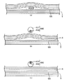
図1は、本発明の一実施形態に係る原理を説明する概念図である。図1(a)は、複数のシートが積層してなるシート束の斜視図であり、図1(b)は、図1(a)に示されるシート束中のシート間の分離を促すとともにシート束からシートを1枚ずつ分離して搬送するシート搬送機構の概念図である。尚、図1に示されるシートは、主に、塗工紙、トレーシングペーパ、OHPフィルムシートとすることができるが、本発明はこれに限られるものではなく、積層して所定時間保管された状態から搬送される任意のシート状物が搬送対象とされてもよい。 FIG. 1 is a conceptual diagram illustrating the principle according to an embodiment of the present invention. FIG. 1A is a perspective view of a sheet bundle formed by stacking a plurality of sheets, and FIG. 1B promotes separation between sheets in the sheet bundle shown in FIG. It is a conceptual diagram of a sheet conveying mechanism that separates and conveys sheets one by one from a bundle. In addition, although the sheet | seat shown by FIG. 1 can be mainly used as a coated paper, a tracing paper, and an OHP film sheet, this invention is not restricted to this, It laminated | stacked and was preserve | saved for the predetermined time. Any sheet-like material conveyed from the state may be a conveyance target.
図1に示されるシート束Tは、積層された複数のシートSを含む。シート束Tを構成するシートSそれぞれは、矩形状の処理面PSと、処理面PSを取り囲む縁部とを含む。縁部は、シートSの搬送方向(図1(a)中、矢印で示される)に対して先頭側に位置する下流縁DEと、下流縁DEに対向する位置に存するとともにシートSの搬送方向に対して後側に位置する上流縁UEと、上流縁UEの両端部それぞれと下流縁DEの両端部それぞれとの間で延びるとともにシートSの搬送方向に沿って延びる一対の側縁SEとを含む。以下の説明において、側縁SEが積み重ねられてなるシート束Tの面(処理面PSに対して直角方向に延びる面)を積層面SSと称する。また、下流縁DEが積み重ねられてなるシート束Tの面(処理面PSに対して直角方向に延びる面)を下流積層面DSと称する。上流縁UEが積み重ねられてなるシート束Tの面(処理面PSに対して直角方向に延びる面)を上流積層面USと称する。積層面SSは、シート束Tの最下位置及び最上位置に存する一対のシートSの側縁SEと、上流縁UEの端部を積層してなる上流端縁UTと、下流縁DEの端部を積層してなる下流端縁DTとで取り囲まれる。上流積層面USは、シート束Tの最下位置及び最上位置に存する一対のシートSの上流縁UEと一対の上流端縁UTとで取り囲まれる。下流積層面DSは、シート束Tの最下位置及び最上位置に存する一対のシートSの下流縁DEと一対の下流端縁DTとで取り囲まれる。以下の説明において、処理面PSには、印刷処理(画像形成処理)が施されるが、本発明はこれに限られるものではなく、例えば、穿孔処理や折り曲げ処理など所望の処理が施されてもよい。 The sheet bundle T shown in FIG. 1 includes a plurality of stacked sheets S. Each of the sheets S constituting the sheet bundle T includes a rectangular processing surface PS and an edge that surrounds the processing surface PS. The edge is located at the leading edge of the sheet S conveyance direction (indicated by an arrow in FIG. 1A) and at a position facing the downstream edge DE, and the sheet S conveyance direction. An upstream edge UE positioned on the rear side, and a pair of side edges SE extending between both ends of the upstream edge UE and both ends of the downstream edge DE and extending along the conveyance direction of the sheet S Including. In the following description, the surface of the sheet bundle T in which the side edges SE are stacked (the surface extending in the direction perpendicular to the processing surface PS) is referred to as a stacked surface SS. Further, the surface of the sheet bundle T formed by stacking the downstream edges DE (the surface extending in the direction perpendicular to the processing surface PS) is referred to as a downstream lamination surface DS. A surface of the sheet bundle T formed by stacking the upstream edges UE (a surface extending in a direction perpendicular to the processing surface PS) is referred to as an upstream lamination surface US. The stacking surface SS includes the lowermost position of the sheet bundle T and the side edges SE of the pair of sheets S existing at the uppermost position, the upstream edge UT formed by stacking the ends of the upstream edges UE, and the ends of the downstream edges DE. And a downstream end edge DT formed by stacking layers. The upstream lamination surface US is surrounded by the lowermost position of the sheet bundle T and the upstream edge UE of the pair of sheets S existing at the uppermost position and the pair of upstream end edges UT. The downstream lamination surface DS is surrounded by the lowermost position of the sheet bundle T and the downstream edge DE of the pair of sheets S existing at the uppermost position and the pair of downstream end edges DT. In the following description, the processing surface PS is subjected to printing processing (image forming processing), but the present invention is not limited to this, and for example, desired processing such as perforation processing or bending processing is performed. Also good.
シート搬送機構600は、シート束Tを収容するシート収容部610を含む。シート収容部610は、例えば、上部が開口した略直方体形状の箱体であり、底部611及び底部611の周縁から上方に向けて延出する周壁部612を含む。シート収容部610内には、例えば、薄板状の支持板620が配設される。支持板620の上面は、シート束Tの下面と当接し、シート収容部610内で、シート束Tを支持する支持面となる。シート搬送機構600は更に、シート束TからシートSを1枚ずつ取り出すとともに搬送する搬送要素630を含む。図1には、搬送要素630として、シート束Tの上面(処理面PS)に回転可能に当接するピックアップローラが示されている。図1に示されるピックアップローラ630は、シートSの下流縁DE近傍でシートSに当接し、シートSの幅方向(搬送方向と直交する方向)に延びている。尚、本発明において、搬送要素630は、図示されるピックアップローラに限られるものではなく、シート束Tからシートを取り出すとともに搬送可能な他の構造とすることもできる。支持板620とシート収容部610の底部611との間には、例えば、バネ体(図示せず)が配設され、支持板620が上方に向けて付勢されることにより、シート束Tの最上位置に存するシートSがピックアップローラ630に押し付けられる。この結果、ピックアップローラ630が回転すると、シート束Tの最上位置に存するシートSがシート束Tから取り出されるとともに搬送されることとなる。
The
シート搬送機構600は更に、送気機構640を含む。送気機構640は、モータ(図示せず)等の駆動源と接続されたファンやモータ(図示せず)等の駆動源を内包するブロアなどの送気源641と、送気源641から送り出される気体を案内する管路642とを含む。管路642の先端部は、積層面SSに向けて開口し、送気源641から送り出される気体を積層面SSに向けて放出する送気口643となる。尚、図1には、背面側に位置する周壁部612に形成された送気口643が点線で示されているが、正面側に位置する周壁部612にも同様の送気口643が形成されてもよい。送気口643は、シート束Tの一部を分離させるとともに浮揚させるのに十分な程度にシート束Tの積層面に近接している。送気源641が送り出す気体は、本実施形態では、例えば、シートSが吸った水成分を蒸発可能な程度に暖気された空気であるが、本発明はこれに限定されるものではなく、例えば、十分に乾燥処理を施された空気や窒素等の特定の成分からなる気体などが所望に応じて使用可能である。
The
シート搬送機構600は更に規制機構650を含む。図1には、規制機構650として、板状の接触部材651と、接触部材651に偏心して接続される回転シャフト652とが示されている。図1に示される接触部材651はカムとして機能する。
The
図2は、図1に示される送気機構640の送気口543におけるシート収容部610の断面図である。図2と併せて図1を参照しつつ、シート搬送機構600の規制機構650について更に説明する。
FIG. 2 is a cross-sectional view of the
図2に示される如く、一対の接触部材651がシート束Tの一対の積層面SSそれぞれの近傍に配される。回転シャフト652は一対の接触部材間で延びる。回転シャフト652は、右方に位置する接触部材651を貫通して更に延びる。回転シャフト652の右端にはギア653が形成される。規制機構650は更に、駆動源として用いられるモータ654を含む。モータ654の回転シャフトの先端部に取り付けられたギア655は、回転シャフト652の右端に配設されるギア653と噛み合う。図2中、右方に示される周壁部612は、背面壁612aであり、左方に示される周壁部612は、正面壁612bである。背面壁612a及び正面壁612bには送気口643が形成され、一対の送気口643は互いに対向する。回転シャフト652は、一対の送気口643を結ぶ線に沿って延びる。接触部材651は、送気口643からの気体が放出される方向上に位置し、シート束Tの外面に現れる最上位置のシートSの面であって、送気口643に対応する面領域に接触する。モータ654が、接触部材651に偏心して取り付けられた回転シャフト652を回転させると、接触部材651は、回転シャフト652とともに一体的に回転し、支持板642の上面に向かう力を間欠的にシート束Tに与えることとなる。
As shown in FIG. 2, a pair of
図3は、図1に示される規制機構650による分離したシート束の浮揚を規制する規制原理を説明する図である。図3(a)は、図1に示される送気機構640によりシート束T中に形成された空気層を示し、図3(b)は、接触部材651の外周輪郭が最も上方に位置する第1位置に存するときのシート束Tを示し、図3(c)は、接触部材651の外周輪郭が最も下方に位置する第2位置に存するときのシート束Tを示す。図3と併せて図1を参照しつつ、分離したシート束の浮揚を規制する規制原理を説明する。
FIG. 3 is a view for explaining a regulation principle for regulating the floating of the separated sheet bundle by the
送気源641の作動により、送気口643から気体が放出される。送気口643から送り出された気体は、シート束Tの積層面SSに衝突する。シート束Tを構成するシートS間の密着力は不均一であり、積層面SSに衝突した気体は、密着力の弱いシートS間に侵入する傾向がある。この結果、送気口643から放出された気体は、シート束を形成するシートSを浮揚させ、シート束T中に気体層(気体の流路)を形成する。
By the operation of the
一旦、気体層が形成されると、送気口643からの気体は、気体層中を通過し続けることとなり、浮揚したシートS間の分離が促進されないこととなる。このため、本実施形態では、規制機構650を用いて、気体層を圧縮することによりシート束Tの浮揚を規制し、シート束Tの他の部分へのシートS間の分離を促している。図3(b)に示される如く、第1位置に接触部材651が存するとき、シート束T中に気体層が形成され、シートS間の分離が促される。その後、回転シャフト652が回転されると、接触部材651は第2位置に達し、気体層を圧縮する。この結果、送気口643から送り出される気体は再度シート束Tの積層面SSに衝突し、新たな気体層をシート束中に形成する。図3(a)及び図3(b)に示される動作を接触部材651が繰り返すことにより、シート束Tの浮揚が間欠式に規制され、シート束T全体において、シートS間の分離が促されることとなる。
Once the gas layer is formed, the gas from the
図4は、図1乃至図3に関連して説明された規制機構650の接触部材651を示す。図4と併せて図1及び図3を参照しつつ、接触部材651について説明する。尚、図4に示される接触部材651は、接触部材651の外周輪郭が最も下方に位置する第2位置に存する。
FIG. 4 shows the
接触部材651が第2位置に存するとき、接触部材651の下端は、ピックアップローラ630の下端よりも僅かに上方(図4中、符号「X」で示される)に配設されてもよい。これにより、シートSの処理面PSに対して平行な方向に働く力を低減させつつ、接触部材651は気体層を圧縮することができる。これにより、シートSの搬送に与える影響を低減しつつ、気体層の圧縮し、シート束の浮揚に対する規制を行なうことが可能となる。
When the
接触部材651は、環状の外輪部511と、外輪部511に取り囲まれる円形の内部空間に外輪部511に対して同心に配設される環状の内輪部512とを有するベアリング513と、内輪部512に嵌め込まれる円形プレート514とを含んでもよい。円形プレート514は、回転シャフト652に接続される。外輪部511は、内輪部512に対して、相対的に回転することが可能である。回転シャフト652の回転と一体的に円形プレート514及び内輪部512は回転する。外輪部511がシートSと接触するとき、外輪部511は内輪部512に対して相対的に回転するので、シートSの処理面PSに対して平行な方向に働く力を低減することが可能である。これにより、シートSの搬送に与える影響を低減しつつ、気体層の圧縮し、シート束の浮揚に対する規制を行なうことが可能となる。
The
図5は、規制機構650の他の実施形態を示す。図1乃至図4に関連して説明された回転動作する接触部材651を備える規制機構650と異なり、図5に示される規制機構650は、上下に往復移動する接触部材651を備える。
FIG. 5 shows another embodiment of the
図5に示される規制機構650は、薄板棒状の接触部材651を備える。接触部材651は、背面壁612a及び正面壁612bに形成された送気口643からの空気の放出方向に沿って延びる。接触部材651の上方に一対のシリンダ656が配設され、一対のシリンダ656のロッド657の先端部それぞれは、接触部材651の両端部の上面に接続される。一対のシリンダ656それぞれは、管路659を用いて、作動流体源658に接続される。管路659の途中部にはソレノイドバルブ660が配設される。ソレノイドバルブ660は、制御部348に電気的に接続される(図5中、点線部参照)。ソレノイドバルブ660は、制御部348の制御下で、作動流体源658からシリンダ656へ送られる作動流体の流動経路を切り換える。これにより、シリンダ656のロッド657を伸縮させる。この結果、接触部材651は上下動し、図3に関連して説明された如く、気体層の圧縮がなされ、シート束の浮揚に対する規制がなされることとなる。
The
図6は、図1及び図2に関連して説明されたシート搬送機構600の原理を適用したストッカが組み込まれた画像形成装置の内部構造を示す。図6と併せて、図1及び図2を参照しつつ、画像形成装置について説明する。尚、図6に示される画像形成装置は、デジタル複写機であるが、本発明はこれに限定されるものではなく、プリンタ、ファクシミリ、画像形成機能を含む複数の機能を有する複合機等或いはシートSの処理面PSに任意の処理を施すための装置とすることができる。
FIG. 6 shows an internal structure of an image forming apparatus incorporating a stocker to which the principle of the
デジタル複写機1は、略直方体に形成された筐体2と、筐体2の内部空間下部に配設されるとともにシートSが蓄えられる貯留部3と、貯留部3からシートSを取り出すとともに搬送する搬送部4と、搬送途中のシートSの面にトナー画像を形成する画像形成部5と、シート上に形成されたトナー画像をシートSの処理面PS上に定着させる定着部6と、トナー画像が定着されたシートSを筐体2外に排出する排出部7とを備える。筐体2の上部には、原稿の画像を読み取るための原稿読取部8が配設される。原稿読取部8は、原稿の画像を読み取り、電子データ化する。
The digital copying machine 1 includes a
貯留部3は、少量のシートSを含むシート束Tを収容する第1カートリッジ31及び第2カートリッジ32を含む。第2カートリッジ32は、第1カートリッジ31の上方に配設される。貯留部3は、第1カートリッジ31及び第2カートリッジ32が収容可能な枚数以上のシートSを含むシート束Tを収容可能に形成されるストッカ33を更に含む。ストッカ33は、第2カートリッジ32の上方に配設される。尚、ストッカ33は、図1及び図2に関連して説明されたシート搬送機構600のシート収容部610に相当する。
The
ストッカ33は、略矩形板状の底部331と、底部331の周縁から上方に向かって延出する周壁部332とを含む。尚、図1及び図2に関連して説明されたシート搬送機構600が備えるシート収容部610の底部611及び周壁部612それぞれは、ストッカ33の底部331及び周壁部332に相当する。周壁部332の上縁は、ストッカ33の開口部を形成する。底部331と周壁部332とで定められるストッカ33の内部空間に収容されたシートSは、ストッカ33の上部に形成される開口部を通じて、搬送部4により取り出され、画像形成部5に向けて搬送される。第1カートリッジ31、第2カートリッジ32及びストッカ33は、筐体2内部から引き出し可能であることが好ましい。
The
ストッカ33は、ストッカ33の内部空間を上下方向に横切って配設される仕切板333を更に含む。仕切板333は、底部331から上方に延出し、図6中において、ストッカ33の内部空間を左右に互いに隣接する小空間に仕切る。左方に形成される小空間を第1収容部と便宜的に称し、右方に形成される小空間を第2収容部と便宜的に称する。第1収容部には、第1トレイ334が配設され、第2収容部には第2トレイ335が配設される。図1に示されるシート搬送機構600の支持板620は、第1トレイ334及び/又は第2トレイ335に相当する。
The
第1収容部に配設されるシート束Tを第1のシート束T1と便宜的に称し、第2収容部に配設されるシート束Tを第2シート束T2と便宜的に称する。第1トレイ334は、第1のシート束T1を支持する支持面を備える。第2トレイ335は、第2のシート束T2を支持する支持面を備える。仕切板333は、第1のシート束T1と第2のシート束T2との間で立設され、第1のシート束T1及び/又は第2のシート束T2が崩れそうになったときにおいて、第1のシート束T1及び/又は第2のシート束T2を側方から支持することができる。仕切板333は、ストッカ33の底部332に対して着脱自在である。
For convenience, the sheet bundle T disposed in the first storage unit will be referred to as a first sheet bundle T1, and the sheet bundle T disposed in the second storage unit will be referred to as a second sheet bundle T2. The
第1のシート束T1が収容される第1収容部を形成する背面側の周壁部332に、図1及び図2に関連して説明された送気口643が形成されている。第2のシート束T2が収容される第2収容部を形成する背面側の周壁部332にも、第1収容部と同様に、送気口643が形成されている(尚、図6において、第2収容部の送気口643は、第2のシート束T2によって、隠されている)。送気口643の上方において、図1及び図2に関連して説明された規制機構650が概略的に示されている。
The
図7は、図6に示される第1収容部又は第2収容部の背面側の周壁部332の外面に取り付けられる送気機構640の概略断面図である。図7と併せて図1、図2及び図6を参照しつつ、送気機構640について説明する。
FIG. 7 is a schematic cross-sectional view of the
図1及び図2において、送気機構640は、非常に概略的に示されたが、送気機構640は、例えば、図7に示される構造を備えることができる。図7に示される送気機構640は、例えば、第1収容部又は第2収容部の背面側の周壁部332の外面に取り付けられるブラケット(図示せず)により支持されることができる。
1 and 2, the
図7に示される送気機構640は、図1及び図3に関連して説明されたように送気源641と管路642とを含む。管路642の基端部は、送気源641の外面を形成する筐体141に一体的に接続される。管路642は、筐体141から延設するエルボ管243を用いて形成される。エルボ管243の先端部は開口し、送気口643となる。
The
筐体141内には、吸引ファン142及びヒータ143が配設される。吸引ファン142は、筐体141外に配設されるモータ144の回転シャフトにより、筐体141内で回転自在に支持される。モータ144が取り付けられる面と反対側の筐体141の面には、開口部145が形成される。モータ144が作動すると、吸引ファン142が回転し、開口部145を介して、送気源641の周囲の空気が筐体141内に引き込まれる。
A
ヒータ143は、管路642と筐体141との接続部と吸引ファン142との間に配設される。吸引ファン142により筐体141内に引き込まれた空気は、ヒータ143及び管路を通過し、送気口643からストッカ33内のシート束Tの積層面SSに向けて放出される。ヒータ143は、ヒータ143を通過する空気を暖める。したがって、送気口643から放出された空気は、ストッカ33内のシート束Tが含む水成分の除去を促し、この結果、シート束TのシートS間の分離が促進されることとなる。
The
尚、図7に関連して説明された送気機構640は、単に説明のために図示されたものであり、本発明を何ら限定するものではなく、シート束Tの積層面SSに向けて空気を放出可能な任意の機構を送気機構640として用いることができる。
Note that the
図8は、第1トレイ334及び第2トレイ335を上下動させるための昇降機構の一例を示す。図8と併せて、図6を参照しつつ、昇降機構について説明する。尚、図8に示される昇降機構は、単に、一例に過ぎず、第1トレイ334及び第2トレイ335を上下動させることが可能な任意の機構を昇降機構として用いてもよい。
FIG. 8 shows an example of an elevating mechanism for moving the
昇降機構34は、第1トレイ334及び第2トレイ335に一端部が接続される複数本のワイヤ341と、第1トレイ334に接続されるワイヤ341の他端部が巻回される第1ドラム342と、第2トレイ335に接続されるワイヤ341の他端部が巻回される第2ドラム343と、第1トレイ334と第1ドラム342とを結ぶワイヤ341の経路及び第2トレイ335と第2ドラム343とを結ぶワイヤ341の経路途中に配設される複数のプーリ345とを含む。
The lifting mechanism 34 includes a plurality of
第1ドラム342は、第1の駆動源346に接続される。第2ドラム343は、第2の駆動源347に接続される。第1の駆動源346及び第2の駆動源347は、制御回路等の制御部348に電気的に接続される。第1の駆動源346及び第2の駆動源347は、制御部348の制御下で、第1ドラム342及び第2ドラム343をそれぞれ駆動する。尚、制御部348は、デジタル複写機1全体の制御を司ることができる。尚、本実施形態において、第1の駆動源346及び第2の駆動源347として、パルスモータやエンコーダ付のモータ等を用いることができるが、第1ドラム342及び第2ドラム343を回転駆動することができる他の装置を用いることも可能である。更に、本実施形態において、第1ドラム342及び第2ドラム343を回転させることにより、ワイヤ341を第1ドラム342及び第2ドラム343に巻きつけて第1トレイ334及び第2トレイ335を上昇させる構造が採用されているが、本発明はこれに限定されず、例えば、回転ドラム342,343並びにこれらに接続する駆動源346,347に代えて、ピストンシリンダを用いることも可能である。ピストンシリンダのロッド先端にワイヤ341の端部を接続し、ロッドをシリンダ本体内に出没させることにより、本実施形態と同様に、第1トレイ334及び第2トレイ335を移動させることができる。
The
仕切板333が、ストッカ33の底部331に取り付けられている間、制御部348は、第1の駆動源346と第2の駆動源347とを独立に制御することができ、例えば、第1の駆動源346及び第2の駆動源347のうち一方のみを動作させることにより、第1トレイ334及び第2トレイ335のうち一方のみを上昇させ、搬送部4へ向けて移動させることができる。したがって、仕切板333が底部331に取り付けられているか否かを検出することができるセンサ装置が用いられてもよい。例えば、このようなセンサ装置として、ストッカ33の底部331に仕切板333が取り付けられたときに仕切板333によって遮られる光路を形成する光センサ等を用いることができる。
While the
第1ドラム342及び/又は第2ドラム343が、図8中、矢印で示される方向に回転すると、ワイヤ341が第1ドラム342及び/又は第2ドラム343に巻き付けられ、第1トレイ334及び/又は第2トレイ335が上昇する。第1トレイ334及び/又は第2トレイ335上にシート束Tが配設されると、シート束Tの自重により、第1トレイ334及び/又は第2トレイ335は下降することができる。尚、昇降機構34は、必要に応じて、第1トレイ334及び/又は第2トレイ335の高さ位置を制御するためのセンサを含むことができる。
When the
搬送部4は、ストッカ33の上部に形成される開口部近傍に配設される給送装置41を含む。昇降機構34は、第1トレイ334及び/又は第2トレイ335を上昇させ、第1トレイ334及び/又は第2トレイ335上のシート束Tを給送装置41まで運ぶ。
The transport unit 4 includes a
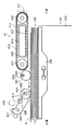
図9は、給送装置41の概略図である。図9と併せて、図6を参照しつつ、給送装置41について説明する。尚、図9は、ストッカ33の第2収容部周囲の構造を併せて示している。図9に示される給送装置41は、図1及び図2に関連して説明された搬送要素630に相当する。
FIG. 9 is a schematic diagram of the
上述の如く、ストッカ33の第2収容部内には、第2トレイ335が配設され、第2トレイ335の上面には、第2のシート束T2が載置される。給送装置41は、ベルト装置412と第2ローラ装置414とを備える。ベルト装置412は、第2のシート束T2の下流積層面DSの上方に配設される。図6に示されるように、給送装置41は、更に、ストッカ33の第1収容部内の第1シート束T1を取り出すための第1ローラ装置413を含む。第1ローラ装置413は、第1シート束の右上面の上方に配設される。第1ローラ装置413及び第2ローラ装置414は互いに略同様の構造をなすことができる。図9には、第2ローラ装置414を駆動するためのモータ415が示されている。
As described above, the
ベルト装置412は、ストッカ33の周壁部332よりも下流側に配設されるとともにベルト装置412の一端部を形成する駆動ローラ416と、ベルト装置412の他端部を形成するとともに駆動ローラ416の駆動力により従動回転する従動ローラ417と、駆動ローラ416と従動ローラ417とに巻回されるベルト418と、駆動ローラ416と従動ローラ417との間に配設される吸引ダクト419とを含む。尚、図9には、駆動ローラ416を駆動するためのモータ421が示されている。吸引ダクト419は、ブロア等の真空源(図示せず)と、真空源に接続される断面矩形状の管路426とを含む。管路426の底壁には、複数の貫通穴427が形成される。貫通穴427並びにベルト418に形成された複数の孔部(図示せず)を通じて、吸引力が第2のシート束T2の最上位置に存するシートSに伝達される。
The
第2ローラ装置414は、第2シート束T2の最上位置に存するシートS上で転動する送りローラ422と、送りローラ422を回転可能に支持する支持部423とを含む。送りローラ422は、送りローラ422の中央に位置する回転シャフト424周りに回転する。支持部423は、支持シャフト425により軸支され、支持シャフト425周りに回動可能である。第2ローラ装置414は更に、支持部423に取り付けられたフォトインタラプタセンサ426を備える。フォトインタラプタセンサ426は、支持部423の姿勢を検知する。図7に関連して説明された昇降機構34が第2トレイ335を上昇させると、第2トレイ335上の第2のシート束T2の上面が送りローラ422に当接し、支持部423が支持シャフト425周りに回転する。フォトインタラプタセンサ426は、支持部423が所定の姿勢(傾斜角度)となったことを検知すると、制御部348(図8参照)に検知信号を送信する。制御部348は、この検知信号に基づき、第2トレイ335の上昇動作を停止させる。モータ415と送りローラ422との間には、ギア機構(図示せず)が構築される。ギア機構は、支持部423の回動を許容しつつ、送りローラ422に駆動力を伝達する。尚、送りローラ422を回転させるためのモータ415は、図2に示される規制機構650を動作させるためのモータ654として用いることもできる。この場合、送りローラ422に駆動力を伝達するためのギア機構は、同時に、接触部材651に接続される回転シャフト652に駆動力を伝達するように構成される。これにより、接触部材651は送りローラ422と同期して回転運動し、図3に関連して説明されたシート束Tの浮揚に対する規制作用をもたらすこととなる。
The
フォトインタラプタセンサ426の検知信号に基づき、第2シート束T2を搬送部4へ搬送するための第2トレイ335の上昇が停止されると、制御部348の制御下で、図7に関連して説明された送気機構640が作動し、送気口643から第2のシート束T2の積層面SSに向けて、温風が放出される。これにより、第2のシート束T2を構成するシートS間に空気が導入されることとなり、シートS間の分離が促される。制御部348はモータ415の制御信号を送信し、モータ415は、制御部348の制御下で、送りローラ422を回転させ、第2のシート束T2の最上位置に存するシートSを左方へ所定距離だけ移動させるとともに接触部材651を動作させ、第2のシート束T2の浮揚に対する規制並びに規制解除を間欠式に繰り返す。この結果、第2のシート束T2のシートS間の分離が促されるとともに第2のシート束T2の最上位置に存するシートSの右縁は、ベルト装置412の吸引ダクト419の下方に位置することとなる。吸引ダクト419からの吸引力は、ベルト418を介して、左方に移動されたシートSの右縁に伝達される。これにより、左方に移動されたシートSの右縁は、ベルト418に吸着され、シートSがストッカ33から取り出されることとなる。その後、制御部348の制御下で、モータ421及び/又はモータ415は、ベルト418及び/又は送りローラ422を反時計回りに回転させ、ベルト418に吸着されたシートSを下流へ送り出す。
When the rising of the
第2収容部内の第2シート束T2を用いて、ストッカ33からのシートSの取り出しについて説明してきたが、上記されたシートSの取り出しの原理及びシートSを取り出すための構造は、第1収容部内の第1のシート束T1に対しても、適用することが可能である。
Although the description has been given of taking out the sheet S from the
図6を再度参照する。搬送部4は、貯留部3の右側で上下方向に延びる搬送路43を含む。ベルト装置412によりストッカ33から取り出されたシートSは、搬送路43に沿って下流へ搬送される。搬送部4は更に、第1カートリッジ31及び第2カートリッジ32の右上部角隅部近傍に配設されるピックアップローラ44及びピックアップローラ44の近傍下流に配設される分離・給紙ローラ45を含む。ピックアップローラ44及び分離・給紙ローラ45は、第1カートリッジ31及び/又は第2カートリッジ32から1枚ずつシートSを取り出し、搬送路43へ搬送する。搬送部4は更に、搬送路43に沿って配設される複数の搬送ローラ46を含む。搬送ローラ46は、ストッカ33、第1カートリッジ31又は第2カートリッジ32から送り出されたシートSを、搬送路43に沿って、画像形成部5へ搬送する。
Reference is again made to FIG. The transport unit 4 includes a
画像形成部5は、筐体2に回転可能に支持される略円筒形状の感光体ドラム51と、感光体ドラム51の上方に配設される帯電器52とを含む。感光体ドラム51は、図6中、時計回りに回転する。帯電器52は、感光体ドラム51に電荷を付与し、感光体ドラム51周面を一様に帯電させる。画像形成部5は更に、露光装置53を備える。露光装置53は、原稿読取部8が原稿の画像を読み取ることにより得られた画像データに基づき、レーザ光を感光体ドラム51の帯電された周面に照射する。この結果、レーザ光は感光体ドラム51上の電荷を消失させるため、感光体ドラム51上には画像データに一致する静電潜像が形成されることとなる。画像形成部5は更に、現像装置54を備える。現像装置54は、トナーを収容するトナーコンテナ55を備え、トナーコンテナ55から静電潜像が形成された感光体ドラム51の周面にトナーを供給する。この結果、感光体ドラム51の周面に、静電潜像に一致するトナー像が形成されることになる。
The
画像形成部5は更に、感光体ドラム51の下方に配設される転写ベルト56を含む。搬送路43を通じて、シートSは、感光体ドラム51と転写ベルト56との間に送り込まれる。感光体ドラム51と転写ベルト56との間をシートSが通過するとき、感光体ドラム51の周面に形成されたトナー像は、トナーの帯電と逆の極性の逆バイアスの印加によりシートSに転写されることとなる。
The
画像形成部5は更に、シートSへトナー像を転写した後の感光体ドラム51の周面上に残留するトナーを除去するクリーニング装置57と、残留トナーの除去がなされた感光体ドラム51の周面から残留電荷を除去する除電装置58とを含む。
The
画像形成部5にて、トナー像の転写がなされたシートSは、定着部6へ送られる。定着部6は、定着ローラ61と、定着ローラ61に圧接される加圧ローラ62とを含む。定着ローラ61の内部には熱源63が配設され、定着ローラ61と加圧ローラ62との間を通過するシートS上のトナーが溶融されるとともに、加圧ローラ62からの圧力によりシートS上にトナーが定着される。これにより、シートS上へのトナー像の定着がなされることとなる。
The sheet S on which the toner image is transferred in the
排出機構7は、定着部6の下流に配設されるとともに筐体2の内壁面近傍に取り付けられる排出ローラ71と、排出ローラ71から筐体2外に排出されたシートSを受け止める排出トレイ72とを含む。
The discharge mechanism 7 is disposed downstream of the fixing
図6に示されるデジタル複写機1は、ストッカ33と画像形成部5/定着部6との間に両面印刷用の搬送路47を備える。排出ローラ71は、スイッチバック方式で搬送路47へシートSを送り出すことも可能である。搬送路47は、搬送路43途中部に配設されたレジストローラ48の直前で合流する。搬送路47を通過したシートSは、レジストローラ48により画像形成部5へ送り出され、画像形成部5内でトナー像が定着されていない面にトナー像の転写がなされる。その後、定着ユニット6により新たに転写されたトナー像のシートSへの定着がなされる。最後に、シートSは排出ローラ71により排紙トレイ72上に排紙されることとなる。
The digital copying machine 1 shown in FIG. 6 includes a
図6に関連して説明されたデジタル複写機1に対して、図1に示された規制機構650が適用されたが、図5に示される規制機構650が適用されてもよい。また、間欠式にシート束Tの浮揚を規制することが可能な他の構造を備える規制機構が適用されてもよい。
Although the
本発明は、プリンタ、複写機、ファクシミリ装置、これらの機能を併せ持つ複合機やシートの面に任意の処理を施す機能を備える各種装置に適用可能である。 The present invention can be applied to a printer, a copier, a facsimile machine, a multi-function machine having these functions, and various apparatuses having a function of performing arbitrary processing on the surface of a sheet.
1・・・・・デジタル複写機
348・・・制御部
620・・・支持板
630・・・搬送要素
640・・・送気機構
650・・・規制機構
651・・・接触部材
652・・・回転シャフト
656・・・シリンダ
657・・・ロッド
660・・・ソレノイドバルブ
S・・・・・シート
SS・・・・積層面
T・・・・・シート束
DESCRIPTION OF SYMBOLS 1 ...
Claims (5)
前記シート束から前記シートを取り出すとともに搬送する搬送要素と、
前記シートの縁部が積み重ねられて形成される前記シート束の積層面に向けて気体を放出し、前記シート束の一部を浮揚させる送気機構と、
前記支持面に向けて間欠式に力を加え、前記シート束の前記一部の浮揚を規制する規制機構と、を備え、
前記送気機構は、前記シートの幅方向において互いに対向して、前記積層面に近接して配設されるとともに前記気体を放出するための一対の送気口を備え、
前記規制機構は、前記一対の送気口を結ぶ線上に設けられ、前記シート束の外面に現れるシートに接触する接触部材を含み、
前記接触部材の下端は、前記搬送要素の下端よりも僅かに上方に配置され、前記一対の送気口に対応する前記シートの面領域に接触することを特徴とするシート搬送機構。 A support surface for supporting a sheet bundle formed by laminating a plurality of sheets;
A conveying element that removes and conveys the sheet from the sheet bundle;
An air supply mechanism that releases a gas toward a stacking surface of the sheet bundle formed by stacking edges of the sheets, and floats a part of the sheet bundle;
A regulation mechanism that applies force intermittently toward the support surface and regulates the levitation of the part of the sheet bundle, and
The air supply mechanism includes a pair of air supply ports that are opposed to each other in the width direction of the sheet and are disposed close to the lamination surface and for releasing the gas,
The restriction mechanism is provided on a line connecting the pair of air supply ports, and includes a contact member that contacts a sheet appearing on an outer surface of the sheet bundle,
The sheet conveying mechanism, wherein a lower end of the contact member is disposed slightly above the lower end of the conveying element and contacts a surface area of the sheet corresponding to the pair of air supply ports.
前記規制機構は、前記接触部材に偏心して接続されるとともに前記接触部材と一体的に回転する回転シャフトと、
該回転シャフトに接続されるとともに該回転シャフトを回転させる駆動源とを更に含むことを特徴とする請求項1記載のシート搬送機構。 The contact member is a cam;
The regulating mechanism is eccentrically connected to the contact member and rotates integrally with the contact member;
The sheet conveying mechanism according to claim 1, further comprising a drive source connected to the rotating shaft and rotating the rotating shaft.
該制御部は、前記送気機構に前記積層面に向けて前記気体を放出させ、前記送気機構が前記気体を放出している間、前記駆動源に前記回転シャフトを回転させるとともに前記搬送要素に前記シート束から前記シートを取り出させることを特徴とする請求項2記載のシート搬送機構。 A control unit;
The control unit causes the air supply mechanism to release the gas toward the laminated surface, and while the air supply mechanism releases the gas, rotates the rotary shaft to the drive source and the transport element. The sheet conveying mechanism according to claim 2, wherein the sheet is taken out from the sheet bundle.
前記シリンダへ向かう作動流体の経路を切り換えるソレノイドバルブと、
前記ソレノイドバルブを制御する制御部と、を更に含むことを特徴とする請求項1記載のシート搬送機構。 The regulating mechanism includes a cylinder having a rod connected to the contact member;
A solenoid valve that switches a path of the working fluid toward the cylinder;
The sheet conveying mechanism according to claim 1, further comprising a control unit that controls the solenoid valve.
該シート搬送機構から送り出された前記シートに画像を形成する画像形成部と、を備え、
前記シート搬送機構は、複数のシートを積層してなるシート束を支持する支持面と、
前記シート束から前記シートを取り出すとともに搬送する搬送要素と、
前記シートの縁部が積み重ねられて形成される前記シート束の積層面に向けて気体を放出し、前記シート束の一部を浮揚させる送気機構と、
前記支持面に向けて間欠式に力を加え、前記シート束の前記一部の浮揚を規制する規制機構と、を備え、
前記送気機構は、前記シートの幅方向において互いに対向して、前記積層面に近接して配設されるとともに前記気体を放出するための一対の送気口を備え、
前記規制機構は、前記一対の送気口を結ぶ線上に設けられ、前記シート束の外面に現れるシートに接触する接触部材を含み、
前記接触部材の下端は、前記搬送要素の下端よりも僅かに上方に配置され、前記一対の送気口に対応する前記シートの面領域に接触することを特徴とする画像形成装置。 A sheet conveying mechanism for accommodating and conveying the sheet;
An image forming unit that forms an image on the sheet fed from the sheet transport mechanism,
The sheet conveying mechanism includes a support surface that supports a sheet bundle formed by stacking a plurality of sheets,
A conveying element that removes and conveys the sheet from the sheet bundle;
An air supply mechanism that releases a gas toward a stacking surface of the sheet bundle formed by stacking edges of the sheets, and floats a part of the sheet bundle;
A regulation mechanism that applies force intermittently toward the support surface and regulates the levitation of the part of the sheet bundle, and
The air supply mechanism includes a pair of air supply ports that are opposed to each other in the width direction of the sheet and are disposed close to the lamination surface and for releasing the gas,
The restriction mechanism is provided on a line connecting the pair of air supply ports, and includes a contact member that contacts a sheet appearing on an outer surface of the sheet bundle,
The image forming apparatus according to claim 1, wherein a lower end of the contact member is disposed slightly above the lower end of the transport element and contacts a surface area of the sheet corresponding to the pair of air supply ports.
Priority Applications (1)
| Application Number | Priority Date | Filing Date | Title |
|---|---|---|---|
| JP2013134619A JP5648093B2 (en) | 2013-06-27 | 2013-06-27 | Sheet conveying mechanism and image forming apparatus incorporating sheet conveying mechanism |
Applications Claiming Priority (1)
| Application Number | Priority Date | Filing Date | Title |
|---|---|---|---|
| JP2013134619A JP5648093B2 (en) | 2013-06-27 | 2013-06-27 | Sheet conveying mechanism and image forming apparatus incorporating sheet conveying mechanism |
Related Parent Applications (1)
| Application Number | Title | Priority Date | Filing Date |
|---|---|---|---|
| JP2009221755A Division JP2011068468A (en) | 2009-09-28 | 2009-09-28 | Sheet carrying mechanism and image forming device incorporated with sheet carrying mechanism |
Publications (2)
| Publication Number | Publication Date |
|---|---|
| JP2013177252A JP2013177252A (en) | 2013-09-09 |
| JP5648093B2 true JP5648093B2 (en) | 2015-01-07 |
Family
ID=49269344
Family Applications (1)
| Application Number | Title | Priority Date | Filing Date |
|---|---|---|---|
| JP2013134619A Expired - Fee Related JP5648093B2 (en) | 2013-06-27 | 2013-06-27 | Sheet conveying mechanism and image forming apparatus incorporating sheet conveying mechanism |
Country Status (1)
| Country | Link |
|---|---|
| JP (1) | JP5648093B2 (en) |
Families Citing this family (1)
| Publication number | Priority date | Publication date | Assignee | Title |
|---|---|---|---|---|
| CN110255233B (en) * | 2019-06-14 | 2024-03-22 | 国网河北省电力有限公司物资分公司 | Two-linked invoice separating device |
Family Cites Families (6)
| Publication number | Priority date | Publication date | Assignee | Title |
|---|---|---|---|---|
| JPH04272036A (en) * | 1991-02-27 | 1992-09-28 | Mitsubishi Materials Corp | Sheet feeding device |
| JPH0659343U (en) * | 1993-01-21 | 1994-08-19 | ジューキ株式会社 | Label pickup device |
| JP3592275B2 (en) * | 2001-08-29 | 2004-11-24 | コニカミノルタホールディングス株式会社 | Paper feeder |
| JP2007022741A (en) * | 2005-07-15 | 2007-02-01 | Oki Electric Ind Co Ltd | Paper sheet separating mechanism, and paper sheet separating and loading mechanism using the same |
| JP4760328B2 (en) * | 2005-11-22 | 2011-08-31 | 富士ゼロックス株式会社 | Paper feeding device and image forming apparatus |
| JP5117162B2 (en) * | 2007-10-29 | 2013-01-09 | 株式会社東芝 | Paper sheet separating apparatus and paper sheet separating method |
-
2013
- 2013-06-27 JP JP2013134619A patent/JP5648093B2/en not_active Expired - Fee Related
Also Published As
| Publication number | Publication date |
|---|---|
| JP2013177252A (en) | 2013-09-09 |
Similar Documents
| Publication | Publication Date | Title |
|---|---|---|
| JP4835489B2 (en) | Paper feeding device and image forming apparatus | |
| JP6663591B2 (en) | Paper feeder and image forming apparatus | |
| JP2008087906A (en) | Paper feeder and image forming device | |
| JP5545526B2 (en) | Paper feeding device and image forming apparatus | |
| JP2009120285A (en) | Paper feeder and image forming device | |
| JP2014152023A (en) | Paper feeder and image forming device | |
| JP2015110464A (en) | Sheet feeder and image formation apparatus | |
| JP2009280345A (en) | Paper feeding device and image forming device equipped with the same | |
| JP5244737B2 (en) | Image forming apparatus | |
| JP4492429B2 (en) | Sheet feeding apparatus and image forming apparatus | |
| JP4208787B2 (en) | Image forming apparatus | |
| JP5648093B2 (en) | Sheet conveying mechanism and image forming apparatus incorporating sheet conveying mechanism | |
| JP2010163254A (en) | Paper feeding device | |
| JP5322848B2 (en) | Image forming apparatus | |
| JP2006027797A (en) | Paper feeding device, and image forming device with the same | |
| JP2011068468A (en) | Sheet carrying mechanism and image forming device incorporated with sheet carrying mechanism | |
| JP2006327716A (en) | Sheet feeding device and image forming device | |
| JP2018111556A (en) | Paper feeding apparatus and image forming apparatus | |
| JP2010215350A (en) | Paper feeder, paper feed unit, and image forming system | |
| JP2011068477A (en) | Sheet carrying mechanism and image forming device incorporated with sheet carrying mechanism | |
| JP5308784B2 (en) | Paper feeding device and image forming apparatus having the same | |
| JPH069083A (en) | Sheet material feed device and image forming device | |
| JP2016160070A (en) | Sheet feeder and image formation apparatus | |
| JP5440774B2 (en) | Recording medium supply apparatus and image forming apparatus | |
| JP5146173B2 (en) | Image forming apparatus |
Legal Events
| Date | Code | Title | Description |
|---|---|---|---|
| A621 | Written request for application examination |
Free format text: JAPANESE INTERMEDIATE CODE: A621 Effective date: 20130627 |
|
| A977 | Report on retrieval |
Free format text: JAPANESE INTERMEDIATE CODE: A971007 Effective date: 20140319 |
|
| A131 | Notification of reasons for refusal |
Free format text: JAPANESE INTERMEDIATE CODE: A131 Effective date: 20140325 |
|
| A521 | Request for written amendment filed |
Free format text: JAPANESE INTERMEDIATE CODE: A523 Effective date: 20140513 |
|
| A02 | Decision of refusal |
Free format text: JAPANESE INTERMEDIATE CODE: A02 Effective date: 20140617 |
|
| A521 | Request for written amendment filed |
Free format text: JAPANESE INTERMEDIATE CODE: A523 Effective date: 20140909 |
|
| A911 | Transfer to examiner for re-examination before appeal (zenchi) |
Free format text: JAPANESE INTERMEDIATE CODE: A911 Effective date: 20140917 |
|
| TRDD | Decision of grant or rejection written | ||
| A01 | Written decision to grant a patent or to grant a registration (utility model) |
Free format text: JAPANESE INTERMEDIATE CODE: A01 Effective date: 20141014 |
|
| A61 | First payment of annual fees (during grant procedure) |
Free format text: JAPANESE INTERMEDIATE CODE: A61 Effective date: 20141110 |
|
| R150 | Certificate of patent or registration of utility model |
Ref document number: 5648093 Country of ref document: JP Free format text: JAPANESE INTERMEDIATE CODE: R150 |
|
| LAPS | Cancellation because of no payment of annual fees |