JP5647524B2 - Apparatus and method for continuously separating and discharging solid catalyst for Fischer-Tropsch synthesis reaction and product - Google Patents
Apparatus and method for continuously separating and discharging solid catalyst for Fischer-Tropsch synthesis reaction and product Download PDFInfo
- Publication number
- JP5647524B2 JP5647524B2 JP2010548602A JP2010548602A JP5647524B2 JP 5647524 B2 JP5647524 B2 JP 5647524B2 JP 2010548602 A JP2010548602 A JP 2010548602A JP 2010548602 A JP2010548602 A JP 2010548602A JP 5647524 B2 JP5647524 B2 JP 5647524B2
- Authority
- JP
- Japan
- Prior art keywords
- product
- solid catalyst
- gas
- fischer
- reactor
- Prior art date
- Legal status (The legal status is an assumption and is not a legal conclusion. Google has not performed a legal analysis and makes no representation as to the accuracy of the status listed.)
- Expired - Fee Related
Links
Images


Classifications
-
- B—PERFORMING OPERATIONS; TRANSPORTING
- B01—PHYSICAL OR CHEMICAL PROCESSES OR APPARATUS IN GENERAL
- B01J—CHEMICAL OR PHYSICAL PROCESSES, e.g. CATALYSIS OR COLLOID CHEMISTRY; THEIR RELEVANT APPARATUS
- B01J8/00—Chemical or physical processes in general, conducted in the presence of fluids and solid particles; Apparatus for such processes
- B01J8/18—Chemical or physical processes in general, conducted in the presence of fluids and solid particles; Apparatus for such processes with fluidised particles
- B01J8/20—Chemical or physical processes in general, conducted in the presence of fluids and solid particles; Apparatus for such processes with fluidised particles with liquid as a fluidising medium
- B01J8/22—Chemical or physical processes in general, conducted in the presence of fluids and solid particles; Apparatus for such processes with fluidised particles with liquid as a fluidising medium gas being introduced into the liquid
-
- B—PERFORMING OPERATIONS; TRANSPORTING
- B01—PHYSICAL OR CHEMICAL PROCESSES OR APPARATUS IN GENERAL
- B01D—SEPARATION
- B01D53/00—Separation of gases or vapours; Recovering vapours of volatile solvents from gases; Chemical or biological purification of waste gases, e.g. engine exhaust gases, smoke, fumes, flue gases, aerosols
-
- B—PERFORMING OPERATIONS; TRANSPORTING
- B01—PHYSICAL OR CHEMICAL PROCESSES OR APPARATUS IN GENERAL
- B01J—CHEMICAL OR PHYSICAL PROCESSES, e.g. CATALYSIS OR COLLOID CHEMISTRY; THEIR RELEVANT APPARATUS
- B01J8/00—Chemical or physical processes in general, conducted in the presence of fluids and solid particles; Apparatus for such processes
- B01J8/005—Separating solid material from the gas/liquid stream
- B01J8/006—Separating solid material from the gas/liquid stream by filtration
-
- B—PERFORMING OPERATIONS; TRANSPORTING
- B01—PHYSICAL OR CHEMICAL PROCESSES OR APPARATUS IN GENERAL
- B01J—CHEMICAL OR PHYSICAL PROCESSES, e.g. CATALYSIS OR COLLOID CHEMISTRY; THEIR RELEVANT APPARATUS
- B01J8/00—Chemical or physical processes in general, conducted in the presence of fluids and solid particles; Apparatus for such processes
- B01J8/18—Chemical or physical processes in general, conducted in the presence of fluids and solid particles; Apparatus for such processes with fluidised particles
- B01J8/1809—Controlling processes
-
- C—CHEMISTRY; METALLURGY
- C10—PETROLEUM, GAS OR COKE INDUSTRIES; TECHNICAL GASES CONTAINING CARBON MONOXIDE; FUELS; LUBRICANTS; PEAT
- C10G—CRACKING HYDROCARBON OILS; PRODUCTION OF LIQUID HYDROCARBON MIXTURES, e.g. BY DESTRUCTIVE HYDROGENATION, OLIGOMERISATION, POLYMERISATION; RECOVERY OF HYDROCARBON OILS FROM OIL-SHALE, OIL-SAND, OR GASES; REFINING MIXTURES MAINLY CONSISTING OF HYDROCARBONS; REFORMING OF NAPHTHA; MINERAL WAXES
- C10G2/00—Production of liquid hydrocarbon mixtures of undefined composition from oxides of carbon
- C10G2/30—Production of liquid hydrocarbon mixtures of undefined composition from oxides of carbon from carbon monoxide with hydrogen
- C10G2/32—Production of liquid hydrocarbon mixtures of undefined composition from oxides of carbon from carbon monoxide with hydrogen with the use of catalysts
- C10G2/34—Apparatus, reactors
- C10G2/342—Apparatus, reactors with moving solid catalysts
-
- B—PERFORMING OPERATIONS; TRANSPORTING
- B01—PHYSICAL OR CHEMICAL PROCESSES OR APPARATUS IN GENERAL
- B01J—CHEMICAL OR PHYSICAL PROCESSES, e.g. CATALYSIS OR COLLOID CHEMISTRY; THEIR RELEVANT APPARATUS
- B01J2208/00—Processes carried out in the presence of solid particles; Reactors therefor
- B01J2208/00008—Controlling the process
- B01J2208/00017—Controlling the temperature
- B01J2208/00026—Controlling or regulating the heat exchange system
- B01J2208/00035—Controlling or regulating the heat exchange system involving measured parameters
- B01J2208/00044—Temperature measurement
- B01J2208/00061—Temperature measurement of the reactants
-
- B—PERFORMING OPERATIONS; TRANSPORTING
- B01—PHYSICAL OR CHEMICAL PROCESSES OR APPARATUS IN GENERAL
- B01J—CHEMICAL OR PHYSICAL PROCESSES, e.g. CATALYSIS OR COLLOID CHEMISTRY; THEIR RELEVANT APPARATUS
- B01J2208/00—Processes carried out in the presence of solid particles; Reactors therefor
- B01J2208/00008—Controlling the process
- B01J2208/00017—Controlling the temperature
- B01J2208/00026—Controlling or regulating the heat exchange system
- B01J2208/00035—Controlling or regulating the heat exchange system involving measured parameters
- B01J2208/0007—Pressure measurement
-
- B—PERFORMING OPERATIONS; TRANSPORTING
- B01—PHYSICAL OR CHEMICAL PROCESSES OR APPARATUS IN GENERAL
- B01J—CHEMICAL OR PHYSICAL PROCESSES, e.g. CATALYSIS OR COLLOID CHEMISTRY; THEIR RELEVANT APPARATUS
- B01J2208/00—Processes carried out in the presence of solid particles; Reactors therefor
- B01J2208/00008—Controlling the process
- B01J2208/0061—Controlling the level
-
- B—PERFORMING OPERATIONS; TRANSPORTING
- B01—PHYSICAL OR CHEMICAL PROCESSES OR APPARATUS IN GENERAL
- B01J—CHEMICAL OR PHYSICAL PROCESSES, e.g. CATALYSIS OR COLLOID CHEMISTRY; THEIR RELEVANT APPARATUS
- B01J2219/00—Chemical, physical or physico-chemical processes in general; Their relevant apparatus
- B01J2219/00049—Controlling or regulating processes
- B01J2219/00191—Control algorithm
- B01J2219/00193—Sensing a parameter
- B01J2219/00195—Sensing a parameter of the reaction system
- B01J2219/002—Sensing a parameter of the reaction system inside the reactor
-
- B—PERFORMING OPERATIONS; TRANSPORTING
- B01—PHYSICAL OR CHEMICAL PROCESSES OR APPARATUS IN GENERAL
- B01J—CHEMICAL OR PHYSICAL PROCESSES, e.g. CATALYSIS OR COLLOID CHEMISTRY; THEIR RELEVANT APPARATUS
- B01J2219/00—Chemical, physical or physico-chemical processes in general; Their relevant apparatus
- B01J2219/00049—Controlling or regulating processes
- B01J2219/00191—Control algorithm
- B01J2219/00211—Control algorithm comparing a sensed parameter with a pre-set value
- B01J2219/00213—Fixed parameter value
-
- B—PERFORMING OPERATIONS; TRANSPORTING
- B01—PHYSICAL OR CHEMICAL PROCESSES OR APPARATUS IN GENERAL
- B01J—CHEMICAL OR PHYSICAL PROCESSES, e.g. CATALYSIS OR COLLOID CHEMISTRY; THEIR RELEVANT APPARATUS
- B01J2219/00—Chemical, physical or physico-chemical processes in general; Their relevant apparatus
- B01J2219/00049—Controlling or regulating processes
- B01J2219/00191—Control algorithm
- B01J2219/00222—Control algorithm taking actions
- B01J2219/00227—Control algorithm taking actions modifying the operating conditions
- B01J2219/00229—Control algorithm taking actions modifying the operating conditions of the reaction system
- B01J2219/00236—Control algorithm taking actions modifying the operating conditions of the reaction system at the reactor outlet
-
- C—CHEMISTRY; METALLURGY
- C10—PETROLEUM, GAS OR COKE INDUSTRIES; TECHNICAL GASES CONTAINING CARBON MONOXIDE; FUELS; LUBRICANTS; PEAT
- C10G—CRACKING HYDROCARBON OILS; PRODUCTION OF LIQUID HYDROCARBON MIXTURES, e.g. BY DESTRUCTIVE HYDROGENATION, OLIGOMERISATION, POLYMERISATION; RECOVERY OF HYDROCARBON OILS FROM OIL-SHALE, OIL-SAND, OR GASES; REFINING MIXTURES MAINLY CONSISTING OF HYDROCARBONS; REFORMING OF NAPHTHA; MINERAL WAXES
- C10G2300/00—Aspects relating to hydrocarbon processing covered by groups C10G1/00 - C10G99/00
- C10G2300/40—Characteristics of the process deviating from typical ways of processing
- C10G2300/4056—Retrofitting operations
-
- C—CHEMISTRY; METALLURGY
- C10—PETROLEUM, GAS OR COKE INDUSTRIES; TECHNICAL GASES CONTAINING CARBON MONOXIDE; FUELS; LUBRICANTS; PEAT
- C10G—CRACKING HYDROCARBON OILS; PRODUCTION OF LIQUID HYDROCARBON MIXTURES, e.g. BY DESTRUCTIVE HYDROGENATION, OLIGOMERISATION, POLYMERISATION; RECOVERY OF HYDROCARBON OILS FROM OIL-SHALE, OIL-SAND, OR GASES; REFINING MIXTURES MAINLY CONSISTING OF HYDROCARBONS; REFORMING OF NAPHTHA; MINERAL WAXES
- C10G2300/00—Aspects relating to hydrocarbon processing covered by groups C10G1/00 - C10G99/00
- C10G2300/40—Characteristics of the process deviating from typical ways of processing
- C10G2300/4081—Recycling aspects
Description
本発明はフィッシャー・トロプシュ合成反応用液体生成物と固体触媒を連続して分離して排出するための装置、及び方法に係り、より詳しくは、合成ガスから合成油を製造するフィッシャー・トロプシュ合成反応において、固体触媒粒子と生成物のスラリーを供給ガスの周期パルス(pulse)によって連続的に分離するだけでなく、液体生成物を反応器の下部に排出させ、長鎖炭化水素(long−chain hydrocarbon)であるワックスを含むフィッシャー・トロプシュ合成の生成物を安定して連続的に生産するようにしたフィッシャー・トロプシュ合成反応用固体触媒と液体生成物を連続して分離して排出する装置、及び方法に関する。 The present invention relates to an apparatus and method for continuously separating and discharging a liquid product for Fischer-Tropsch synthesis reaction and a solid catalyst, and more particularly, Fischer-Tropsch synthesis reaction for producing synthetic oil from synthesis gas. In addition to continuously separating the slurry of solid catalyst particles and the product by a periodic pulse of the feed gas, the liquid product is discharged to the bottom of the reactor and a long-chain hydrocarbon (long-chain hydrocarbon). And a solid catalyst for Fischer-Tropsch synthesis reaction and a liquid product for separating and discharging the liquid product continuously, which stably produce a Fischer-Tropsch synthesis product containing wax About.
近年、石油の価格が急激に高騰し、輸送用燃料や石油化学産業の原料として石油に代わって天然ガスを用いるガス液化油(GTL)工程に対する関心が高まってきている。実際に、一酸化炭素の水素化反応であるフィッシャー・トロプシュ合成(Fischer−Tropsch Synthesis)に関する研究は1970年代初頭まで活発ではなかったが、近年の石油価格の高騰により、フィッシャー・トロプシュ法に関する関心が再び高くなっている。 In recent years, the price of petroleum has soared, and interest in gas liquefied oil (GTL) processes that use natural gas instead of petroleum as a fuel for transportation and petrochemical industries has increased. In fact, research on Fischer-Tropsch Synthesis, which is a hydrogenation reaction of carbon monoxide, was not active until the early 1970s, but due to the recent rise in oil prices, interest in Fischer-Tropsch methods has increased. It is getting higher again.
GTL工程に含まれる技術には、合成ガス改質、精製技術などのさまざまな技術があるが、合成ガスから合成炭化水素を製造するフィッシャー・トロプシュ合成反応は核となる技術とみなされている。
合成ガス(CO+H2)から合成油を生成するために、フィッシャー・トロプシュ合成工程で使用される合成ガスの組成及び触媒によって多様な生成物が合成される。
The technologies included in the GTL process include various technologies such as synthesis gas reforming and purification technologies, but the Fischer-Tropsch synthesis reaction for producing synthetic hydrocarbons from synthesis gas is regarded as a core technology.
To produce synthetic oil from synthesis gas (CO + H 2 ), various products are synthesized depending on the composition and catalyst of the synthesis gas used in the Fischer-Tropsch synthesis process.
一般に、H2/COの比が2以上の合成ガスを使ってフィッシャー・トロプシュ合成工程を行う場合、大量の硬質炭化水素生成物が合成され、一方、H2/COの比が2未満の合成ガスを使ってフィッシャー・トロプシュ合成工程を行う場合、ガソリン(C5〜C11)、ディーゼル(C12〜C18)、ワックス(>C24)などが合成される。
前記のH2/COの比に従って、鉄基、またはコバルト基のフィッシャー・トロプシュ触媒が工業規模で使用されている。
また、合成条件を変えて多様な化学製品(炭化水素、アルコール、エーテル、酢酸など)を生産することができる。
In general, when a Fischer-Tropsch synthesis process is performed using a synthesis gas having a H 2 / CO ratio of 2 or more, a large amount of hard hydrocarbon product is synthesized, while a synthesis with a H 2 / CO ratio of less than 2 is synthesized. When performing the Fischer-Tropsch synthesis process using gas, gasoline (C 5 -C 11 ), diesel (C 12 -C 18 ), wax (> C 24 ), etc. are synthesized.
Depending on the H 2 / CO ratio, iron-based or cobalt-based Fischer-Tropsch catalysts are used on an industrial scale.
In addition, various chemical products (hydrocarbon, alcohol, ether, acetic acid, etc.) can be produced by changing the synthesis conditions.
米国特許第5543437A号(Charles B.Benham,Arvada)、及び国際公開公報第WO2005/090521号(Compact GTL plc、Mike Bowe、Joseph)には、天然ガスから合成油などの長鎖炭化水素を製造する方法が開示されている。 US Pat. No. 5,543,437 A (Charles B. Benham, Arvada) and International Publication No. WO 2005/090521 (Compact GTL plc, Mike Bowe, Joseph) produce long chain hydrocarbons such as synthetic oils from natural gas. A method is disclosed.
一般に、フィッシャー・トロプシュ合成のための反応装置は、固定床反応器(FBR)、スラリー気泡塔反応器(SBCR)、及び流動床反応器に分類され、現在固定床反応器とスラリー気泡塔反応器が一般に使用されている。 Generally, reactors for Fischer-Tropsch synthesis are classified into fixed bed reactor (FBR), slurry bubble column reactor (SBCR), and fluidized bed reactor, and currently fixed bed reactor and slurry bubble column reactor. Is commonly used.
フィッシャー・トロプシュ合成に用いられるパイロット規模の反応器として、スラリー気泡塔反応器は固定床反応器に比べて次のような利点を持っている。
スラリー気泡塔反応器は、
1)熱伝逹効率が高い
2)反応器の軸方向に沿った圧力降下、及び温度勾配(すなわち、ホットスポット)がない
3)運転中でも触媒の添加、排出及び再生が可能である
4)設置が容易である
5)効率のよい方法で設置可能である
6)収率(反応器容積当たりの生産量)が高い
7)大容量の反応器を有する。
As a pilot scale reactor used for Fischer-Tropsch synthesis, a slurry bubble column reactor has the following advantages over a fixed bed reactor.
The slurry bubble column reactor
1) High heat transfer efficiency 2) No pressure drop along the axial direction of the reactor and no temperature gradient (ie hot spot) 3) Addition, discharge and regeneration of catalyst are possible even during operation 4) Installation 5) Can be installed in an efficient manner 6) High yield (production per reactor volume) 7) Has a large capacity reactor.
このような利点によりスラリー気泡塔反応器は固定床反応器よりも広く使用されている。しかし、スラリー気泡塔反応器はスラリーの再循環手段、及びスラリーから固体触媒と液状生成物とを分離することができる分離手段が必要となる。
また、スラリー気泡塔反応器内の触媒粒子は、運転時間が経過するにつれて、すり減ってより微細な粒子となり、スラリー再循環手段及び分離手段の効率が低下して、スラリー気泡塔反応器の外部に排出されるおそれがある。従って、スラリー気泡塔反応器の内部のスラリー濃度、及び運転条件が変わるため、生成物を均一、且つ持続的に得ることができなくなる。
Because of these advantages, slurry bubble column reactors are more widely used than fixed bed reactors. However, the slurry bubble column reactor requires slurry recirculation means and separation means capable of separating the solid catalyst and the liquid product from the slurry.
In addition, the catalyst particles in the slurry bubble column reactor are worn away to become finer particles as the operation time elapses, and the efficiency of the slurry recirculation means and the separation means is reduced, and the catalyst particle outside the slurry bubble column reactor is removed. There is a risk of being discharged. Accordingly, since the slurry concentration inside the slurry bubble column reactor and the operating conditions change, the product cannot be obtained uniformly and continuously.
米国特許第5,599,849A号(Berend Jager)には、スラリー気泡塔フィッシャー・トロプシュ合成反応器において、スラリー分離手段としてスラリー気泡塔反応器の上部に設置された複数の濾材ユニット(filtering medium unit)を用いて液体生成物を連続的に分離排出させ、スラリー分離手段で8バール(bar)以上の圧力降下が発生すると、液体生成物と高圧ガスを利用してスラリー分離手段を初期状態に戻す逆洗過程(back flush)が開示されている。 U.S. Pat. No. 5,599,849A (Berend Jager) describes a plurality of filter medium units installed at the top of a slurry bubble column reactor as slurry separation means in a slurry bubble column Fischer-Tropsch synthesis reactor. ) To separate and discharge the liquid product continuously, and when a pressure drop of 8 bar or more occurs in the slurry separation means, the slurry separation means is returned to the initial state using the liquid product and the high-pressure gas. A back flush process is disclosed.
しかしながら、前記特許は、運転時間の経過とともにスラリー分離手段に作用する圧力損失が増加することになり、これにより反応器の圧力が上昇して反応物の高さが高くなり、スラリー濃度が低くなる。このような運転条件の変化は、均一なフィッシャー・トロプシュ合成反応を誘導しにくいだけでなく、逆洗過程において逆洗媒体である生成物及び高圧ガスが反応器内の圧力をさらに高めて正常運転に悪影響を及ぼすおそれがある。 However, in the above patent, the pressure loss acting on the slurry separation means increases with the passage of operating time, thereby increasing the pressure of the reactor, increasing the height of the reactants, and lowering the slurry concentration. . Such changes in operating conditions not only make it difficult to induce a uniform Fischer-Tropsch synthesis reaction, but the product and high-pressure gas, which are backwashing media in the backwashing process, further increase the pressure in the reactor and operate normally. May be adversely affected.
また、分離手段、及び生成物排出手段は、反応器の上部に配置されており、鎖成長によって粘性、及び比重が増加して、フィッシャー・トロプシュ反応によって生成される所望の生成物が反応器の下部に位置するので、所望の長鎖炭化水素の代わりに短鎖の炭化水素が得られる。 The separation means and the product discharge means are arranged at the upper part of the reactor, and the viscosity and specific gravity increase due to chain growth, so that the desired product produced by the Fischer-Tropsch reaction can be obtained. Because it is located at the bottom, short chain hydrocarbons are obtained instead of the desired long chain hydrocarbons.
米国特許第5,422,375A号(Erling Rytter)には、フィッシャー・トロプシュ合成反応器の内部に圧力変動用スラリー分離手段を備えることで、反応物の高さが上昇すればスラリー分離手段にかかる真空を感知してスラリーを連続的に分離、排出する方法が開示されている。
しかし、前記方法は実用的ではなく、分離手段に欠陷が発生すれば修復しにくいという欠点を持っている。
In US Pat. No. 5,422,375A (Erling Rytter), a slurry separation means for pressure fluctuation is provided inside the Fischer-Tropsch synthesis reactor, and the slurry separation means is applied when the height of the reactant is increased. A method for continuously separating and discharging slurry by sensing a vacuum is disclosed.
However, this method is not practical and has a drawback that it is difficult to repair if a defect occurs in the separating means.
また、米国特許第7,144,924B2号(Gabriele Carlo Ettore Clerici)は、スラリー分離方法として水力サイクロン(hydro−cyclone)について開示している。水力サイクロンの効率はスラリー濃度及び触媒粒子の大きさ分布によって大きな影響を受ける。
しかし、残念ながら、スラリー気泡塔反応器での触媒粒子は運転時間の経過とともに摩耗するので、水力サイクロンは実用的ではない。
U.S. Patent No. 7,144,924 B2 (Gabriel Carlo Ettore Clerici) discloses a hydro-cyclone as a slurry separation method. Hydrocyclone efficiency is greatly affected by slurry concentration and catalyst particle size distribution.
Unfortunately, however, the hydrocyclone is not practical because the catalyst particles in the slurry bubble column reactor wear out over time.
従って、フィッシャー・トロプシュ合成用スラリー気泡塔反応器において固体触媒、及び生成物混合スラリーを連続的に分離するとともに、生成された生成物の量だけ質の高い長鎖炭化水素生成物を均一に排出させることができるフィッシャー・トロプシュ合成方法の開発が必要である。 Therefore, in the Fischer-Tropsch synthesis slurry bubble column reactor, the solid catalyst and the product mixed slurry are continuously separated, and high-quality long-chain hydrocarbon products are uniformly discharged by the amount of the produced products. It is necessary to develop a Fischer-Tropsch synthesis method.
本発明は、固体触媒粒子と液体生成物の混合スラリーとを連続的に分離するだけでなく、生成物を生成量の分だけ排出させて反応器の内部のスラリー濃度を均一に維持することによって、安定した運転条件下で、長鎖炭化水素合成油を連続的に製造するようにしたフィッシャー・トロプシュ合成反応用の固体触媒と液体生成物を連続して分離して排出するための装置及び方法を提供する。 The present invention not only continuously separates the solid catalyst particles and the mixed slurry of the liquid product, but also discharges the product by the amount produced to maintain a uniform slurry concentration inside the reactor. , Apparatus and method for continuously separating and discharging a solid catalyst and a liquid product for Fischer-Tropsch synthesis reaction for continuous production of long-chain hydrocarbon synthetic oil under stable operating conditions I will provide a.
また、本発明は、スラリー分離手段の圧力降下が増加して分離効率が低下した場合、反応条件を変更せず、スラリー分離手段の分離効率を初期状態に回復させて均一な反応を維持させることができるようにしたフィッシャー・トロプシュ合成反応用固体触媒と液体生成物を連続して分離して排出するための装置及び方法を提供する。 Further, the present invention maintains the uniform reaction by restoring the separation efficiency of the slurry separation means to the initial state without changing the reaction conditions when the pressure drop of the slurry separation means increases and the separation efficiency is lowered. An apparatus and a method for continuously separating and discharging a solid catalyst for a Fischer-Tropsch synthesis reaction and a liquid product are provided.
本発明は、供給ガスから合成油を合成することによるフィッシャー・トロプシュ合成反応のための固体触媒と液体生成物を連続して分離して排出するための装置であって、前記装置は、反応器の内部に設置され、スラリー段階の反応物の高さを感知するレベル感知手段と、前記反応器の下部に設置され、前記反応器の内部を上側部分と下側部分に分け、前記反応器の前記上側部分で混合された前記固体触媒と前記液体生成物の混合物を濾過する分離手段と、前記下側部分に配置され、分離された前記液体生成物を排出する生成物排出用流量制御バルブと、前記レベル感知手段から感知信号を受信して前記生成物排出用流量制御バルブの開閉動作を制御する制御部と、を有し、前記生成物排出用流量制御バルブは前記固体触媒から分離された液体生成物を前記反応器の前記下側部分で、前記レベル感知手段によって測定された合成生成物の生成量の分だけ連続的に排出するフィッシャー・トロプシュ合成反応用固体触媒と液体生成物を連続して分離して排出するための装置であって、前記上側部分と前記下側部分に設置され、前記上側部分と前記下側部分の間の圧力降下を感知する差圧センサーと、前記供給ガスを前記上側部分に供給するガス分配器を有するフィルター再生手段と、を有し、前記分離手段は、前記分離手段上に位置する前記混合物を濾過して前記液体生成物を前記下側部分に移動させるように構成され、前記制御部は、前記差圧センサーから感知信号を受信し、圧力降下が所定のレベルに増加すると、前記生成物排出用流量制御バルブを閉鎖し、前記フィルター再生手段は、前記下側部分に前記供給ガスの周期的なガスパルスを供給することで、前記分離手段に前記供給ガスの周期的なガスパルスを噴射させ、前記固体触媒が融着、または沈積された前記分離手段を洗浄し、前記分離手段を初期状態に戻すように構成され、前記レベル感知手段は、レーダー式、または超音波式レベルセンサーと熱電対のいずれか一方、或いはレベルセンサーと熱電対の両方を有し、前記熱電対は、スラリー段階の反応物と排ガスが満たされた気体段階の空間の間の温度差によって反応物のスラリーレベルを感知することを特徴とする装置である。
本発明は、前記分離手段は、一定の細孔サイズを持つ固体触媒、及び液体生成物とを分離するためのフィルターであることを特徴とするフィッシャー・トロプシュ合成反応用固体触媒と生成物を連続して分離して排出するための装置である。
本発明は、前記分離手段は、平面フィルター、又は分離面積が平面フィルターに比べて相対的に大きいカートリッジ式フィルターあることを特徴とするフィッシャー・トロプシュ合成反応用固体触媒と生成物を連続して分離して排出するための装置である。
本発明は、前記生成物排出用流量制御バルブの開閉動作を制御する駆動手段とを有し、前記駆動手段はモーター、又はシリンダーであることを特徴とするフィッシャー・トロプシュ合成反応用固体触媒と生成物を連続して分離して排出するための装置である。
本発明は、前記フィルター再生手段は、供給ガスを前記反応器の内部に均一に注入し、固体触媒/生成物混合物が前記分離手段に流入することを妨げないために、複数のノズルを持つガス分配器と、前記ガス分配器に供給ガスを供給するガス注入用流量制御バルブと、前記ガス注入用流量制御バルブの開閉動作を制御する駆動手段とを有し、前記駆動手段はモーター、又はシリンダーであることを特徴とするフィッシャー・トロプシュ合成反応用固体触媒と生成物を連続して分離して排出するための装置である。
本発明は、前記ガス分配器は内部でガスが流れる管状のシリンダーを有し、前記管状のシリンダーは複数列で平行に配置されているか、又は中心部から放射方向に延びていることを特徴とするフィッシャー・トロプシュ合成反応用固体触媒と生成物を連続して分離して排出するための装置である。
本発明は、反応器内で供給ガスから合成油を合成することによるフィッシャー・トロプシュ合成反応のための固体触媒と液体生成物を連続して分離して排出するための方法であって、前記反応器の内部の下部に設置された分離手段によって前記反応器の内部は上側部分と下側部分とに分けられており、前記方法は、ガス分配器から前記供給ガスを前記上側部分に供給してフィッシャー・トロプシュ合成反応を進行させ、反応の進行具合に応じてレベル感知手段によって反応物のスラリーレベルを測定しており、前記レベル感知手段によって反応物が第1の基準レベル(高レベル)に達したと感知した場合は、前記分離手段によって固体触媒と液体生成物の混合物を濾過した後、前記下側部分に設置された生成物排出用流量制御バルブを開放して液体生成物を排出する段階と、前記生成物排出用流量制御バルブによって生成物を排出することにより反応物の高さが下がり、前記レベル感知手段によって反応物が第2の基準レベル(低レベル)に達したと感知した場合は、前記生成物排出用流量制御バルブを遮断する段階と、前記反応器の前記上側部分と前記下側部分に設置された差圧センサーが、前記生成物排出用流量制御バルブの排出回数が増加するにつれて前記分離手段に融着及び堆積した固体触媒量の増加量によって生じる前記上側部分と前記下側部分の間の圧力降下量を感知し、前記圧力降下量が所定のレベルを超過する場合は、前記生成物排出用流量制御バルブを閉鎖し、前記下側部分に前記供給ガスの周期的なガスパルスを供給することで、前記分離手段に前記供給ガスを噴射し、前記堆積した固体触媒を除去するフィルター再生段階と、を有し、前記レベル感知手段には、レーダー式、または超音波式レベルセンサーと熱電対のいずれか一方、或いはレベルセンサーと熱電対の両方が用いられ、前記熱電対は、スラリー段階の反応物と排ガスが満たされた気体段階の空間の間の温度差によって反応物のスラリーレベルを感知することを特徴とするフィッシャー・トロプシュ合成反応用固体触媒と生成物を連続して分離して排出するための方法である。
本発明は、前記分離手段は平面フィルター、又は分離面積が平面フィルターより相対的に大きいカートリッジ式フィルターであり、一定サイズの微細孔を持つ固体触媒及び生成物分離用フィルターであることを特徴とするフィッシャー・トロプシュ合成反応用固体触媒と生成物を連続して分離して排出するための方法である。
本発明は、前記フィルター再生手段は、供給ガスを前記反応器の内部に均一に注入し、固体触媒/液体生成物の混合物が前記分離手段に流入することを妨げないために、複数のノズルを持つガス分配器と、前記ガス分配器に供給ガスを供給するガス注入用流量制御バルブと、前記ガス注入用流量制御バルブの開閉動作を制御する駆動手段とを有し、前記駆動手段はモーター、又はシリンダーであることを特徴とするフィッシャー・トロプシュ合成反応用固体触媒と生成物を連続して分離して排出するための方法である。
The present invention is an apparatus for continuously separating and discharging a solid catalyst and a liquid product for a Fischer-Tropsch synthesis reaction by synthesizing synthetic oil from a feed gas, the apparatus comprising a reactor A level sensing means for sensing the height of the reactant in the slurry stage, and a lower part of the reactor, the interior of the reactor being divided into an upper part and a lower part, Separation means for filtering the mixture of the solid catalyst and the liquid product mixed in the upper part; a product discharge flow control valve disposed in the lower part and for discharging the separated liquid product; A control unit that receives a sensing signal from the level sensing means and controls an opening / closing operation of the product discharge flow control valve, and the product discharge flow control valve is separated from the solid catalyst. liquid The Fischer-Tropsch synthesis reaction solid catalyst and the liquid product are continuously discharged in the lower part of the reactor, and the product is continuously discharged by an amount corresponding to the production amount of the synthesis product measured by the level sensing means. An apparatus for separating and discharging, a differential pressure sensor installed in the upper part and the lower part for sensing a pressure drop between the upper part and the lower part, and the supply gas Filter regeneration means having a gas distributor for feeding to the upper part, the separation means filtering the mixture located on the separation means and moving the liquid product to the lower part The control unit receives a sensing signal from the differential pressure sensor, and closes the product discharge flow control valve when the pressure drop increases to a predetermined level, and regenerates the filter. Stage by supplying a periodic gas pulses of the feed gas to the lower portion, the periodic gas pulses of the feed gas is injected into the separation unit, wherein the solid catalyst is fused or deposited, the The separation unit is cleaned and the separation unit is returned to an initial state. The level detection unit is either a radar type or an ultrasonic level sensor and a thermocouple, or both the level sensor and the thermocouple. The thermocouple is a device that senses the slurry level of the reactant according to a temperature difference between the slurry phase reactant and the gas phase space filled with exhaust gas .
In the present invention, the separation means is a filter for separating a solid catalyst having a constant pore size and a liquid product, and the Fischer-Tropsch synthesis reaction solid catalyst and the product are continuously provided. It is a device for separating and discharging.
In the present invention, the separation means is a flat filter or a cartridge type filter having a relatively large separation area as compared with the flat filter, and continuously separates the solid catalyst for Fischer-Tropsch synthesis reaction and the product. It is a device for discharging.
The present invention has a driving means for controlling the opening and closing operation of the product discharge flow control valve, and the driving means is a motor or a cylinder, and a Fischer-Tropsch synthesis reaction solid catalyst and production It is an apparatus for separating and discharging things continuously.
The present invention provides a gas having a plurality of nozzles so that the filter regeneration means uniformly injects a feed gas into the reactor and does not prevent a solid catalyst / product mixture from flowing into the separation means. A distributor, a gas injection flow control valve for supplying a supply gas to the gas distributor, and a drive means for controlling an opening / closing operation of the gas injection flow control valve, the drive means being a motor or a cylinder It is an apparatus for separating and discharging a solid catalyst for Fischer-Tropsch synthesis reaction and a product continuously.
The present invention is characterized in that the gas distributor has a tubular cylinder through which gas flows, and the tubular cylinders are arranged in parallel in a plurality of rows or extend radially from the center. The Fischer-Tropsch synthesis reaction solid catalyst and product are continuously separated and discharged.
The present invention is a method for continuously separating and discharging a solid catalyst and a liquid product for a Fischer-Tropsch synthesis reaction by synthesizing synthetic oil from a feed gas in a reactor, The inside of the reactor is divided into an upper part and a lower part by a separating means installed at the lower part of the inside of the reactor, and the method supplies the supply gas from a gas distributor to the upper part. The Fischer-Tropsch synthesis reaction is advanced, and the slurry level of the reactant is measured by the level sensing means according to the progress of the reaction, and the reactant reaches the first reference level (high level) by the level sensing means. If the separation means detects that the mixture of the solid catalyst and the liquid product is filtered, the product discharge flow control valve installed in the lower part is opened. The step of discharging the liquid product and the discharge of the product by the flow control valve for discharging the product lowers the height of the reactant, and the level sensing means causes the reactant to reach the second reference level (low level). The product discharge flow control valve is shut off, and a differential pressure sensor installed in the upper part and the lower part of the reactor is connected to the product discharge flow rate. As the number of discharges of the control valve increases, a pressure drop amount between the upper part and the lower part caused by an increase in the amount of solid catalyst fused and deposited on the separation means is sensed, and the pressure drop quantity is predetermined. if it exceeds the level of, and closing the product discharge flow control valve, by supplying a periodic gas pulses of the feed gas to the lower portion, the feed gas to the separation means Injected, have a, a filter regeneration removing the solid catalyst described above deposited, the said level sensing means, Radar, or either one of the ultrasonic level sensor and a thermocouple, or the level sensor and the thermocouple The Fischer-Tropsch synthesis reaction is characterized in that the thermocouple senses the slurry level of the reactant by the temperature difference between the slurry stage reactant and the gas stage space filled with exhaust gas. This is a method for continuously separating and discharging a solid catalyst for use and a product.
The present invention is characterized in that the separation means is a flat filter or a cartridge type filter having a separation area relatively larger than that of the flat filter, and is a solid catalyst and product separation filter having fine pores of a certain size. This is a method for continuously separating and discharging a solid catalyst for Fischer-Tropsch synthesis reaction and a product.
In the present invention, the filter regeneration means uniformly injects the feed gas into the reactor and does not prevent the solid catalyst / liquid product mixture from flowing into the separation means. A gas distributor, a gas injection flow control valve for supplying a supply gas to the gas distributor, and a drive means for controlling the opening / closing operation of the gas injection flow control valve, the drive means being a motor, Alternatively, the solid catalyst for the Fischer-Tropsch synthesis reaction and the product, which are characterized by being a cylinder, are continuously separated and discharged.
以上説明したように、本発明によるフィッシャー・トロプシュ合成反応用固体触媒と生成物を連続して分離して排出するための装置及び方法によれば、レベル感知手段によって反応物の高さを均一に維持し、反応器の下部に設置された生成物分離及び排出手段によって生成物を反応器の下部を通って連続的に分離、排出することにより、フィッシャー・トロプシュ反応によって生成された生成物を連続的に得ることができる。 As described above, according to the apparatus and method for continuously separating and discharging the Fischer-Tropsch synthesis reaction solid catalyst and product according to the present invention, the level of the reactant is made uniform by the level sensing means. The product produced by the Fischer-Tropsch reaction is continuously maintained by continuously separating and discharging the product through the lower part of the reactor by means of product separation and discharge installed at the lower part of the reactor. Can be obtained.
また、生成物分離のためのフィルターに周期的なガスパルスを噴射させてフィルターを初期状態に戻すことにより、分離、排出及び周期的な復元過程によって生成物を長期間連続的に製造することができる。 In addition, by injecting periodic gas pulses to the product separation filter and returning the filter to the initial state, the product can be continuously produced for a long period of time by separation, discharge and periodic restoration process. .
また、従来のフィッシャー・トロプシュ反応用気泡塔反応器に必要不可欠であった水力サイクロン及びスラリー再循環手段などが要求されないので、フィッシャー・トロプシュ(FT)反応器を簡単に製作し、容易に運転することができ、触媒の摩耗によるFT反応器の効率低下を減少させることができる。 In addition, the hydrocyclone and slurry recirculation means, which are indispensable for conventional bubbler reactors for Fischer-Tropsch reactions, are not required, so a Fischer-Tropsch (FT) reactor can be easily manufactured and operated easily. And the reduction in efficiency of the FT reactor due to catalyst wear can be reduced.
以下、本発明の好適な実施例を添付図面に基づいて詳細に説明する。
図2は本発明によるフィッシャー・トロプシュ合成反応のための固体触媒と生成物を連続して分離して排出するための装置を概略的に示している。
図2を参照すると、スラリー気泡塔反応器12の上部には反応物の高さを感知することができるレベルセンサー(level sensor)10、及び熱電対(thermocouples)11が備えられ、スラリー気泡塔反応器12の下部には固体触媒/生成物(ワックス)分離手段と生成物排出手段が備えられている。
Hereinafter, preferred embodiments of the present invention will be described in detail with reference to the accompanying drawings.
FIG. 2 schematically shows an apparatus for continuously separating and discharging the solid catalyst and product for the Fischer-Tropsch synthesis reaction according to the present invention.
Referring to FIG. 2, a slurry
一般に、フィッシャー・トロプシュ合成のためのスラリー気泡塔反応器12において、CO及びH2を含む供給ガスはスラリー気泡塔反応器12の下部を通って注入され、スラリー気泡塔反応器12内にスラリー状態の固体触媒15と化学反応を起こして下記式1に示すようにワックスなどの炭化水素(hydrocarbon)を合成する。本フィッシャー・トロプシュ合成は発熱反応であるので、冷却手段が必要となる。
In general, in a slurry
![]()
![]()
フィッシャー・トロプシュ反応に広く利用される触媒としては、コバルト(Co)基触媒、及び鉄(Fe)基触媒がある。コバルト触媒は200〜260℃、1.0〜3.0MPaの反応条件で合成油、及びワックスを生成させることができ、鉄触媒は300〜350℃、1.0〜3.0MPaの反応条件でディーゼル、及びナフサ(naphtha)を合成させることができる。 Catalysts widely used for the Fischer-Tropsch reaction include a cobalt (Co) based catalyst and an iron (Fe) based catalyst. The cobalt catalyst can generate synthetic oil and wax under the reaction conditions of 200 to 260 ° C. and 1.0 to 3.0 MPa, and the iron catalyst can be generated under the reaction conditions of 300 to 350 ° C. and 1.0 to 3.0 MPa. Diesel and naphtha can be synthesized.
本発明はコバルト触媒存在下でのワックス合成に関するものである。フィッシャー・トロプシュ反応によって合成されたワックスは、C12〜C200程度のハイドロカーボンであり、望ましくはC23〜C48程度のハイドロカーボンである。カーボン原子の数は、運転方式及び条件を制御することによって調節される。また、スラリー反応用フィッシャー・トロプシュ反応に利用されるコバルト触媒の平均粒子の大きさは30〜150μm程度である。
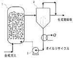
一般に、フィッシャー・トロプシュ反応によって合成された生成物は、触媒/生成物混合スラリー状態で反応器1の外部に排出され、分離手段2に移動して最終生成物が得られる。図1に示すように、反応器1の外部で分離された触媒を反応器1の内部に再注入するためにスラリーポンプ3のようなスラリー再循環手段が必要とされる。
The present invention relates to wax synthesis in the presence of a cobalt catalyst. The wax synthesized by the Fischer-Tropsch reaction is a hydrocarbon of about C 12 to C 200 , preferably a hydrocarbon of about C 23 to C 48 . The number of carbon atoms is adjusted by controlling the operating mode and conditions. The average particle size of the cobalt catalyst used in the Fischer-Tropsch reaction for slurry reaction is about 30 to 150 μm.
In general, the product synthesized by the Fischer-Tropsch reaction is discharged to the outside of the
米国特許第5,599,849A号(Berend Jager)に示すように、反応器内部の上部に備えられた触媒/生成物分離手段を利用して反応器12の外部に直接生成物を排出させることもできる。
前記のように、従来のフィッシャー・トロプシュ合成に用いられる気泡塔反応器で合成された生成物は反応器の上部を通って排出される。しかしながら、長鎖炭化水素を有するワックスは、高品質、高粘性、高比重、及び高沸点であるので、フィッシャー・トロプシュ合成の生成物であるワックスは反応器の下部に位置する。
As shown in US Pat. No. 5,599,849A (Berend Jager), the product is discharged directly to the outside of the
As mentioned above, the product synthesized in the bubble column reactor used in conventional Fischer-Tropsch synthesis is discharged through the top of the reactor. However, since waxes with long chain hydrocarbons are of high quality, high viscosity, high specific gravity, and high boiling point, the wax that is the product of the Fischer-Tropsch synthesis is located at the bottom of the reactor.
図2に示すように、本発明によれば、分離/排出手段はスラリー気泡塔反応器12の下部に備えられているので、フィッシャー・トロプシュ反応によって合成された長鎖炭化水素を有するワックスを効果的に得ることができる。
スラリー気泡塔反応器12においてフィッシャー・トロプシュ合成反応が進むにつれて、スラリー状態の反応物の高さはフィッシャー・トロプシュ合成で生成された生成物の量だけ増加することになる。スラリー気泡塔反応器12の上部に備えられたレベルセンサー10または熱電対11によって、スラリー気泡塔反応器12の内部の反応物の高さを感知する。反応物の高さが所定の高レベル値に達すると、スラリー気泡塔反応器12の下部に備えられた生成物排出用駆動手段17が、レベルセンサーから信号を受信し、生成物排出流量制御バルブ18を開いて反応物の高さが所定の低レベル値に達するまで生成物を排出する。
As shown in FIG. 2, according to the present invention, since the separation / discharge means is provided at the lower part of the slurry
As the Fischer-Tropsch synthesis reaction proceeds in the slurry
この際、スラリー状態の反応物の中で、スラリー気泡塔反応器12の下部に設置された焼結金属フィルター24によって固体触媒15が濾過され、液体生成物がスラリー気泡塔反応器12の外部に排出される。反応物が低レベルに到逹すれば、駆動手段17がレベルセンサーから信号を受信して生成物排出用流量制御バルブ18を閉鎖状態にし、生成される生成物によってスラリー気泡塔反応器12の内部の反応物の高さは高レベルまで上昇することになる。
このような過程を繰り返すことにより、レベルセンサー10または熱電対11が受信する信号によって生成物排出用流量制御バルブ18が開かれることになり、生成物がスラリー気泡塔反応器12の外部に所定量排出される。均一な運転条件を持つために、スラリー気泡塔反応器12の内部の反応物の高さ、及びスラリー濃度が一定に維持されるようにすることにより、高純度の生成物を得ることができる。
At this time, among the reactants in the slurry state, the
By repeating such a process, the product discharge
レベル感知手段としては、レーダー式、または超音波式高温高圧レベルセンサー10と熱電対11のいずれも使用可能である。フィッシャー・トロプシュ反応において、スラリー段階の反応物はスラリー気泡塔反応器(SBCR)の軸方向に沿って温度勾配がないが、スラリー段階の反応物と排ガスで満たされた気相スペースでは、10〜30℃の範囲の温度差があるので、熱電対11がレベル感知手段として使用可能である。
As the level sensing means, either radar type or ultrasonic type high temperature and high
特に、スラリー気泡塔反応器12の規模が小さくてレベルセンサー10を設置することができない場合、或いはレベルセンサー10にたびたび不具合が生じる場合には、スラリー気泡塔反応器12においては、出力信号を伝達することができる熱電対11の方がレベルセンサー10より効率的に使用される。
また、固体触媒/生成物の分離手段としては、高温高圧に耐えられる細孔径約5〜15μmの焼結金属フィルター24が好ましい。焼結金属フィルター24の細孔径が小さすぎる場合は、焼結金属フィルター24の上下部に著しい圧力降下がかかって、触媒、及びワックスの分離速度が低下する。一方、焼結金属フィルター24の細孔径が大きすぎる場合は、細かく摩耗された触媒を効果的に分離することができない。従って、焼結金属フィルター24は、約5〜15μmの細孔径が好ましい。
In particular, when the scale of the slurry
As the solid catalyst / product separation means, a
前記スラリー分離及び生成物排出過程が連続的に進む過程で、スラリー分離手段である焼結金属フィルター24の極小細孔に触媒粒子が融着するか堆積し、生成物が円滑に分離/排出されない場合には、焼結金属フィルター24の上下部の圧力降下が増加することになる。
このような問題点を解決するために、本発明では、焼結金属フィルター24の上下部に電子式差圧センサー20を設置しており、焼結金属フィルター24の上部、或いは下部で圧力降下が発生すると、焼結金属フィルター24の上下部に設置された電子式差圧センサー20が圧力降下を感知し、制御部16で感知された信号を受信して駆動手段21に制御信号を伝送し、駆動手段21によってガス注入用流量制御バルブ22を制御する。
In the course of continuous progress of the slurry separation and product discharge process, catalyst particles are fused or deposited on the very small pores of the
In order to solve such problems, in the present invention, the electronic
前記感知信号によって生成物排出用流量制御バルブ18は閉鎖され、それ以上の生成物は排出されなくなる。スラリー気泡塔反応器12の側面に配置されたガス注入用流量制御バルブ22は、スラリー気泡塔反応器12の下部で生成物を排出する配管方向に開放され、焼結金属フィルターに供給ガスを用いた周期的なガスパルスを供給して、焼結金属フィルター24の上下部で増加する圧力降下を初期状態に戻す。従って、連続的なスラリーの分離、及び生成物の排出を初期状態に戻すことができる。
The product discharge
ここで、駆動手段17、21は流量制御バルブ18、22を開閉するための駆動力を提供する手段であり、ギアとモーターアッセンブリー、或いは油圧ピストンとシリンダーアッセンブリーによって構成される。
また、焼結金属フィルター24のガスパルスとして利用されるガスはフィッシャー・トロプシュ反応の供給ガスであり、ガスパルスのために使用された後、スラリー気泡塔反応器12に移され、フィッシャー・トロプシュ反応の供給ガスとして使用される。
Here, the driving means 17 and 21 are means for providing a driving force for opening and closing the flow
The gas used as the gas pulse of the
供給ガスを利用した焼結金属フィルター24の逆洗によれば、逆洗過程でもフィッシャー・トロプシュ反応の条件を変化させることがない。
フィッシャー・トロプシュ合成は高温、且つ高圧で行われるので、円滑に生成物を排出するためには、生成物バッファタンク19が用いられることが好ましい。
According to the backwashing of the
Since the Fischer-Tropsch synthesis is performed at a high temperature and a high pressure, the
図3は、カートリッジ式の固体触媒/ワックス分離手段の平面図、及び正面図を示す。本発明で使用される焼結金属フィルターとしては、平面フィルター24、あるいは図3のようなカートリッジ式フィルター25のいずれも可能である。
平面焼結金属フィルター24は実験室規模、或いはベンチスケールのスラリー気泡塔反応器12で用いられ、複数のカートリッジユニットを用い、広い分離面積を有するカートリッジ式焼結金属フィルター25は、パイロットスケール気泡塔反応器12、或いはより大規模な反応器で用いられる。
FIG. 3 shows a plan view and a front view of the cartridge type solid catalyst / wax separation means. As the sintered metal filter used in the present invention, either a
The flat
カートリッジ式フィルター25は平面フィルター24よりも分離面積が広いので、固体触媒/ワックスの分離速度を増加させ、カートリッジ式フィルター25を用いるガスパルスの周期を遅らせることによって、ガス注入用流量制御バルブ22の寿命を延ばすことができる。
Since the
図4a、及び図4bはガス分配器23(或いはスパージャー)を示し、図4aは多列管式ガス分配器であり、図4bはスパイダー式ガス分配器である。
ガス分配器23は供給ガスをスラリー気泡塔反応器12に均一に注入することができ、さらに、固体触媒/生成混合物と焼結金属フィルター24との接触を妨げることがない。従って、ガス分配器23には、所定サイズの穴を有する板型よりも、多数のノズル27を持つ管式(図4a)、或いは多数のノズル27を持つスパイダー式(図4b)が好適であり、ガス分配器23は、焼結金属フィルター24の上部に備えられてもよい。
4a and 4b show the gas distributor 23 (or sparger), FIG. 4a is a multi-row tube type gas distributor, and FIG. 4b is a spider type gas distributor.
The
本発明を以下の実施例に基づいてより詳細に説明するが、以下の実施例は例示を目的としているのであって、本発明の範囲が以下の実施例に限定されるものではない。 The present invention will be described in more detail based on the following examples. However, the following examples are for illustrative purposes, and the scope of the present invention is not limited to the following examples.
実施例及び比較例
図5は、直径0.05m、高さ1.5mのフィッシャー・トロプシュ合成反応器(220℃、20bar)における、実施例1、及び比較例1の固体触媒/ワックスの分離排出回数に基づく焼結金属フィルターに作用する圧力降下、及び生成物(ワックス)の排出速度を示している。
図5(実施例1(ガスパルス))に示されるように、固体触媒/ワックスの分離排出回数が増加するにつれて、焼結金属フィルターの上下部に生じる圧力降下が増加する。圧力降下が増加すると、ワックスの排出速度も落ちることになる。
Example and Comparative Example FIG. 5 shows the separation discharge of the solid catalyst / wax of Example 1 and Comparative Example 1 in a Fischer-Tropsch synthesis reactor (220 ° C., 20 bar) having a diameter of 0.05 m and a height of 1.5 m. The pressure drop acting on the sintered metal filter based on the number of times and the discharge rate of the product (wax) are shown.
As shown in FIG. 5 (Example 1 (gas pulse)), as the number of solid catalyst / wax separation discharges increases, the pressure drop generated in the upper and lower portions of the sintered metal filter increases. As the pressure drop increases, so does the wax discharge rate.
生成物排出が8回行われ、ワックスの排出速度が約0.01L/cm2/min(基準値を0.02L/cm2/minとする場合)になると、供給ガスを利用して焼結金属フィルターにガスパルスを供給する。
ガスパルスを2分間供給すると、圧力降下、及びワックスの排出速度は初期状態に戻る。以後さらに9回生成物を排出すれば、圧力降下がさらに増加して、ワックスの排出速度が約0.01L/cm2/minに減少する。ガスパルスを10分間供給することによって、圧力降下、及びワックス排出速度は、初期状態よりも優れた状態に戻される。この過程を繰り返すことにより、固体触媒/ワックスの分離手段を最適化した状態で運転することができる。
When the product discharge is performed 8 times and the wax discharge rate is about 0.01 L / cm 2 / min (when the reference value is 0.02 L / cm 2 / min), the supply gas is used for sintering. Supply a gas pulse to the metal filter.
When the gas pulse is supplied for 2 minutes, the pressure drop and the wax discharge rate return to the initial state. Thereafter, if the product is discharged nine more times, the pressure drop is further increased and the wax discharge rate is reduced to about 0.01 L / cm 2 / min. By supplying the gas pulse for 10 minutes, the pressure drop and the wax discharge rate are returned to a better state than the initial state. By repeating this process, the solid catalyst / wax separation means can be operated in an optimized state.
一方、図5の比較例1に示されるように、ガスパルスを実施しない場合、固体触媒/ワックスの分離排出回数が10回以上になると、焼結金属フィルターの上下部で生じる圧力降下が融着された触媒ケーキによって9バール(bar)まで増加することになり、圧力降下の急増によってワックスの排出も不可能になる。 On the other hand, as shown in Comparative Example 1 of FIG. 5, when the gas pulse is not performed, the pressure drop generated at the upper and lower parts of the sintered metal filter is fused when the solid catalyst / wax separation / discharge frequency is 10 times or more. The catalyst cake will increase to 9 bar, and the rapid increase in pressure drop makes wax discharge impossible.
図6は、フィッシャー・トロプシュ合成反応器において、ガスパルス時間に基づく焼結金属フィルターに作用する圧力降下、及び生成物排出速度を示す。
焼結金属フィルターに作用する圧力降下は、ガスパルスの時間が経過するにつれて減少し、ワックス排出速度が増加する。ワックス排出速度は10分後には最高値に達し、その後も一定に維持されることが分かる。
FIG. 6 shows the pressure drop acting on the sintered metal filter based on the gas pulse time and the product discharge rate in the Fischer-Tropsch synthesis reactor.
The pressure drop acting on the sintered metal filter decreases as the time of the gas pulse elapses and the wax discharge rate increases. It can be seen that the wax discharge rate reaches a maximum value after 10 minutes and remains constant thereafter.
図5、及び図6を参照すると、直径5cmのフィッシャー・トロプシュ反応器の焼結金属フィルターの逆洗浄は、固体触媒/ワックスの分離排出を8回行った後、10分間のガスパルスを行うことによって最適化される。焼結金属フィルターの上下部で7バールの圧力降下が検知されると、逆洗浄はレベルセンサー10、差圧センサー20、及び触媒/ワックス分離手段によって自動的に行われ、それによって最適化された条件でフィッシャー・トロプシュ反応を継続的に行う。
Referring to FIGS. 5 and 6, the backwashing of the sintered metal filter of the 5 cm diameter Fischer-Tropsch reactor is performed by performing a gas pulse for 10 minutes after separating and discharging the solid catalyst /
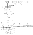
図7は本発明によるベンチ−スケール(0.1バーレル/日)のフィッシャー・トロプシュ合成反応器12を概略的に示している。
FIG. 7 schematically shows a bench-scale (0.1 barrel / day) Fischer-
本発明によれば、従来のフィッシャー・トロプシュ合成用スラリー気泡塔反応器には必要不可欠な固体触媒/ワックスの分離手段である水力サイクロンとスラリー再循環手段である高温高圧スラリーポンプが必要なく、さらに、合成されたワックスをスラリー気泡塔反応器12の下部を通って排出させることにより、動作条件を一定に維持させながら高品質の長鎖炭化水素生成物を連続的に得ることができ、触媒の摩耗によるFT反応器の効率低下を抑制することができる。
According to the present invention, the conventional slurry bubble column reactor for Fischer-Tropsch synthesis does not require a hydrocyclone as a solid catalyst / wax separation means and a high-temperature / high-pressure slurry pump as a slurry recirculation means, By discharging the synthesized wax through the lower part of the slurry
当業者であれば、本発明の精神、または範囲から逸脱することなく、様々な改変、及びバリエーションを行うことが可能であろう。本発明から想起される他の実施例は、ここに開示した本発明の明細書を考慮し、実施することによって、当業者には明らかであるだろう。本発明の明細書、及び実施例は、例としてみなされるべきであり、本発明の正確な範囲、及び精神は以下の特許請求の範囲によって示されるものとする。 Those skilled in the art will be able to make various modifications and variations without departing from the spirit or scope of the present invention. Other embodiments envisioned by the present invention will be apparent to those skilled in the art from consideration and practice of the specification of the invention disclosed herein. The specification and examples of the present invention should be considered as examples, the exact scope and spirit of the present invention being indicated by the following claims.
10: レベルセンサー
11: 熱電対
12: スラリー気泡塔反応器
15: スラリー状態の固体触媒
16: 制御部
17: 生成物排出用駆動手段
18: 生成物排出用流量制御バルブ
19: 生成物バッファタンク
20: 電子式差圧センサー
21: ガス注入用駆動手段
22: ガス注入用流量制御バルブ
23: ガス分配器
24: 固体触媒/生成物混合焼結金属フィルター
25: カートリッジ式フィルター
26: 金属シール
27: ノズル
DESCRIPTION OF SYMBOLS 10: Level sensor 11: Thermocouple 12: Slurry bubble column reactor 15:
Claims (9)
反応器の内部に設置され、スラリー段階の反応物の高さを感知するレベル感知手段と、
前記反応器の下部に設置され、前記反応器の内部を上側部分と下側部分に分け、前記反応器の前記上側部分で混合された前記固体触媒と前記液体生成物の混合物を濾過する分離手段と、
前記下側部分に配置され、分離された前記液体生成物を排出する生成物排出用流量制御バルブと、
前記レベル感知手段から感知信号を受信して前記生成物排出用流量制御バルブの開閉動作を制御する制御部と、
を有し、
前記生成物排出用流量制御バルブは前記固体触媒から分離された液体生成物を前記反応器の前記下側部分で、前記レベル感知手段によって測定された合成生成物の生成量の分だけ連続的に排出するフィッシャー・トロプシュ合成反応用固体触媒と液体生成物を連続して分離して排出するための装置であって、
前記上側部分と前記下側部分に設置され、前記上側部分と前記下側部分の間の圧力降下を感知する差圧センサーと、
前記供給ガスを前記上側部分に供給するガス分配器を有するフィルター再生手段と、を有し、
前記分離手段は、前記分離手段上に位置する前記混合物を濾過して前記液体生成物を前記下側部分に移動させるように構成され、
前記制御部は、前記差圧センサーから感知信号を受信し、圧力降下が所定のレベルに増加すると、前記生成物排出用流量制御バルブを閉鎖し、前記フィルター再生手段は、前記下側部分に前記供給ガスの周期的なガスパルスを供給することで、前記分離手段に前記供給ガスの周期的なガスパルスを噴射させ、
前記固体触媒が融着、または沈積された前記分離手段を洗浄し、前記分離手段を初期状態に戻すように構成され、
前記レベル感知手段は、レーダー式、または超音波式レベルセンサーと熱電対のいずれか一方、或いはレベルセンサーと熱電対の両方を有し、
前記熱電対は、スラリー段階の反応物と排ガスが満たされた気体段階の空間の間の温度差によって反応物のスラリーレベルを感知することを特徴とする装置。 An apparatus for continuously separating and discharging a solid catalyst and a liquid product for a Fischer-Tropsch synthesis reaction by synthesizing synthetic oil from a feed gas, the apparatus comprising:
Level sensing means installed inside the reactor to sense the height of the reactant in the slurry stage;
Separation means installed at the lower part of the reactor, dividing the interior of the reactor into an upper part and a lower part, and filtering the mixture of the solid catalyst and the liquid product mixed in the upper part of the reactor When,
A product discharge flow control valve disposed in the lower portion and for discharging the separated liquid product;
A control unit that receives a sensing signal from the level sensing means and controls the opening and closing operation of the product discharge flow control valve;
Have
The product discharge flow control valve continuously converts the liquid product separated from the solid catalyst in the lower part of the reactor by the amount of synthesis product measured by the level sensing means. An apparatus for continuously separating and discharging a solid catalyst for Fischer-Tropsch synthesis reaction and a liquid product to be discharged,
A differential pressure sensor installed in the upper part and the lower part for sensing a pressure drop between the upper part and the lower part;
Filter regeneration means having a gas distributor for supplying the supply gas to the upper part,
The separation means is configured to filter the mixture located on the separation means to move the liquid product to the lower portion;
The control unit receives a sensing signal from the differential pressure sensor, and closes the product discharge flow control valve when the pressure drop increases to a predetermined level, and the filter regeneration means has the lower part in the lower part. By supplying a periodic gas pulse of the supply gas, the separation means is made to inject a periodic gas pulse of the supply gas,
The separation means on which the solid catalyst is fused or deposited is washed, and the separation means is returned to an initial state .
The level sensing means has either a radar type or an ultrasonic level sensor and a thermocouple, or both a level sensor and a thermocouple ,
The thermocouple senses the slurry level of the reactant by a temperature difference between the slurry-stage reactant and a gas-stage space filled with exhaust gas .
前記駆動手段はモーター、又はシリンダーであることを特徴とする請求項3に記載のフィッシャー・トロプシュ合成反応用固体触媒と生成物を連続して分離して排出するための装置。 Driving means for controlling the opening and closing operation of the product discharge flow control valve,
4. The apparatus for continuously separating and discharging the Fischer-Tropsch synthesis reaction solid catalyst and product according to claim 3 , wherein the driving means is a motor or a cylinder.
前記駆動手段はモーター、又はシリンダーであることを特徴とする請求項1に記載のフィッシャー・トロプシュ合成反応用固体触媒と生成物を連続して分離して排出するための装置。 The filter regeneration means uniformly injects the feed gas into the reactor and does not prevent a solid catalyst / product mixture from flowing into the separation means; a gas distributor having a plurality of nozzles; A gas injection flow control valve for supplying a supply gas to the gas distributor; and a driving means for controlling an opening / closing operation of the gas injection flow control valve;
The apparatus for continuously separating and discharging the solid catalyst for Fischer-Tropsch synthesis reaction and the product according to claim 1, wherein the driving means is a motor or a cylinder.
前記反応器の内部の下部に設置された分離手段によって前記反応器の内部は上側部分と下側部分とに分けられており、
前記方法は、
ガス分配器から前記供給ガスを前記上側部分に供給してフィッシャー・トロプシュ合成反応を進行させ、
反応の進行具合に応じてレベル感知手段によって反応物のスラリーレベルを測定しており、
前記レベル感知手段によって反応物が第1の基準レベル(高レベル)に達したと感知した場合は、前記分離手段によって固体触媒と液体生成物の混合物を濾過した後、前記下側部分に設置された生成物排出用流量制御バルブを開放して液体生成物を排出する段階と、
前記生成物排出用流量制御バルブによって生成物を排出することにより反応物の高さが下がり、前記レベル感知手段によって反応物が第2の基準レベル(低レベル)に達したと感知した場合は、前記生成物排出用流量制御バルブを遮断する段階と、
前記反応器の前記上側部分と前記下側部分に設置された差圧センサーが、前記生成物排出用流量制御バルブの排出回数が増加するにつれて前記分離手段に融着及び堆積した固体触媒量の増加量によって生じる前記上側部分と前記下側部分の間の圧力降下量を感知し、前記圧力降下量が所定のレベルを超過する場合は、前記生成物排出用流量制御バルブを閉鎖し、前記下側部分に前記供給ガスの周期的なガスパルスを供給することで、前記分離手段に前記供給ガスを噴射し、前記堆積した固体触媒を除去するフィルター再生段階と、
を有し、
前記レベル感知手段には、レーダー式、または超音波式レベルセンサーと熱電対のいずれか一方、或いはレベルセンサーと熱電対の両方が用いられ、
前記熱電対は、スラリー段階の反応物と排ガスが満たされた気体段階の空間の間の温度差によって反応物のスラリーレベルを感知することを特徴とするフィッシャー・トロプシュ合成反応用固体触媒と生成物を連続して分離して排出するための方法。 A method for continuously separating and discharging a solid catalyst and a liquid product for a Fischer-Tropsch synthesis reaction by synthesizing synthetic oil from a feed gas in a reactor,
The inside of the reactor is divided into an upper part and a lower part by a separating means installed in the lower part of the inside of the reactor,
The method
Supplying the supply gas from a gas distributor to the upper part to advance the Fischer-Tropsch synthesis reaction;
The slurry level of the reactant is measured by the level sensing means according to the progress of the reaction,
If the level sensing means senses that the reactant has reached the first reference level (high level), the separation means filters the mixture of the solid catalyst and the liquid product, and then is installed in the lower portion. Discharging the liquid product by opening the flow control valve for discharging the product,
When the product is discharged by the product discharge flow control valve, the height of the reactant is reduced, and when the level sensing means senses that the reactant has reached the second reference level (low level), Shutting off the product discharge flow control valve;
The differential pressure sensors installed in the upper part and the lower part of the reactor increase the amount of solid catalyst fused and deposited on the separation means as the number of discharges of the product discharge flow control valve increases. A pressure drop between the upper part and the lower part caused by the amount is sensed, and if the pressure drop exceeds a predetermined level, the product discharge flow control valve is closed and the lower part is A filter regeneration step of injecting the supply gas into the separation means and removing the deposited solid catalyst by supplying a periodic gas pulse of the supply gas to a portion;
I have a,
As the level detection means, either a radar type or an ultrasonic type level sensor and a thermocouple, or both a level sensor and a thermocouple are used.
The thermocouple senses the slurry level of the reactant by the temperature difference between the slurry-stage reactant and the gas-stage space filled with exhaust gas, and the Fischer-Tropsch synthesis reaction solid catalyst and product For continuous separation and discharge.
The filter regeneration means is a gas distributor having a plurality of nozzles in order to uniformly inject the feed gas into the reactor and not to prevent the solid catalyst / liquid product mixture from flowing into the separation means. And a gas injection flow control valve for supplying a supply gas to the gas distributor, and a drive means for controlling the opening / closing operation of the gas injection flow control valve, wherein the drive means is a motor or a cylinder. The method for separating and discharging the solid catalyst for Fischer-Tropsch synthesis reaction according to claim 8 and the product continuously.
Applications Claiming Priority (3)
| Application Number | Priority Date | Filing Date | Title |
|---|---|---|---|
| KR10-2008-0018679 | 2008-02-29 | ||
| KR1020080018679A KR100992835B1 (en) | 2008-02-29 | 2008-02-29 | The continuous separation and discharge apparatus and method of solid catalysts and product product for Fischer-Tropsch synthesis reactions |
| PCT/KR2008/007250 WO2009107927A1 (en) | 2008-02-29 | 2008-12-08 | Method and apparatus for the continuous seperation and discharge of solid catalysts and products for fischer-tropsch synthesis reactions |
Publications (2)
| Publication Number | Publication Date |
|---|---|
| JP2011522900A JP2011522900A (en) | 2011-08-04 |
| JP5647524B2 true JP5647524B2 (en) | 2014-12-24 |
Family
ID=41016280
Family Applications (1)
| Application Number | Title | Priority Date | Filing Date |
|---|---|---|---|
| JP2010548602A Expired - Fee Related JP5647524B2 (en) | 2008-02-29 | 2008-12-08 | Apparatus and method for continuously separating and discharging solid catalyst for Fischer-Tropsch synthesis reaction and product |
Country Status (7)
| Country | Link |
|---|---|
| US (1) | US8852516B2 (en) |
| EP (1) | EP2249945B1 (en) |
| JP (1) | JP5647524B2 (en) |
| KR (1) | KR100992835B1 (en) |
| CN (1) | CN101959575B (en) |
| AU (1) | AU2008351486B2 (en) |
| WO (1) | WO2009107927A1 (en) |
Families Citing this family (13)
| Publication number | Priority date | Publication date | Assignee | Title |
|---|---|---|---|---|
| JP5675146B2 (en) * | 2010-03-30 | 2015-02-25 | 独立行政法人石油天然ガス・金属鉱物資源機構 | Process for producing hydrocarbons |
| US9243988B2 (en) | 2010-07-08 | 2016-01-26 | Exxonmobil Chemical Patents Inc. | System and method for monitoring bubble formation within a reactor |
| US9296833B2 (en) | 2010-07-08 | 2016-03-29 | Exxonmobil Chemical Patents Inc. | Method for controlling bubble formation in polymerization reactors |
| KR101210397B1 (en) * | 2010-09-17 | 2012-12-10 | 한국화학연구원 | Catalyst/Wax separation device in a slurry phase Fischer-Tropsch synthesis reactor system |
| US9849434B2 (en) * | 2010-09-22 | 2017-12-26 | Grupo Petrotemex, S.A. De C.V. | Methods and apparatus for enhanced gas distribution |
| US9545622B2 (en) | 2010-10-11 | 2017-01-17 | Exxonmobil Chemical Patents Inc. | Activation and use of hydroalkylation catalysts |
| JP5703096B2 (en) | 2011-03-31 | 2015-04-15 | 独立行政法人石油天然ガス・金属鉱物資源機構 | Method for estimating content of fine particles in slurry and method for producing hydrocarbon oil |
| JP5808559B2 (en) | 2011-03-31 | 2015-11-10 | 独立行政法人石油天然ガス・金属鉱物資源機構 | Hydrocarbon oil production method, Fischer-Tropsch synthesis reactor, and hydrocarbon oil production system |
| CN103182221B (en) * | 2011-12-29 | 2017-03-01 | Cap Iii 有限公司 | The method separating solid catalyst particle from inorganic process liquid |
| CN109762600A (en) * | 2017-11-09 | 2019-05-17 | 陕西未来能源化工有限公司 | A kind of Low Temperature Fischer Tropsch synthesis paraffin classification cycle filtration system |
| CN108465281B (en) * | 2018-05-28 | 2023-09-19 | 浙江东瓯过滤机制造有限公司 | Filtering and concentrating device and filtering and concentrating method thereof |
| CN109289712A (en) * | 2018-12-04 | 2019-02-01 | 怀化学院 | Experimental reactor |
| CN113457611B (en) * | 2021-07-06 | 2022-08-05 | 江西鑫铂瑞科技有限公司 | Electrolytic copper foil copper dissolving material process capable of reducing energy consumption |
Family Cites Families (22)
| Publication number | Priority date | Publication date | Assignee | Title |
|---|---|---|---|---|
| US3542674A (en) * | 1968-07-22 | 1970-11-24 | Owens Corning Fiberglass Corp | Method for removing solids suspensions in liquids |
| FR2385429A1 (en) * | 1977-03-28 | 1978-10-27 | Degremont | METHOD AND APPARATUS FOR SEPARATION OF EMULSIONS BY COALESCENCE |
| FR2529905B1 (en) * | 1982-07-09 | 1988-04-08 | Inst Francais Du Petrole | PROCESS AND DEVICE FOR HYDROPROCESSING HYDROCARBONS IN LIQUID PHASE, IN THE PRESENCE OF A CATALYST IN EXPANDED OR BOILING BED |
| US4487065A (en) * | 1983-03-07 | 1984-12-11 | Cypher Systems | Storage tank level monitoring apparatus and method therefor |
| EP0221209A1 (en) * | 1985-10-10 | 1987-05-13 | Mobil Oil Corporation | Multi-phase countercurrent reactor process and apparatus |
| US4550012A (en) * | 1984-05-01 | 1985-10-29 | Mobil Oil Corp. | Multi-phase countercurrent reactor system |
| US4580597A (en) * | 1985-04-15 | 1986-04-08 | Monsanto Company | Fluid distribution system |
| US5543437A (en) * | 1986-05-08 | 1996-08-06 | Rentech, Inc. | Process for the production of hydrocarbons |
| GB9203959D0 (en) * | 1992-02-25 | 1992-04-08 | Norske Stats Oljeselskap | Method of conducting catalytic converter multi-phase reaction |
| US5599849A (en) * | 1993-01-27 | 1997-02-04 | Sasol Chemical Industries (Proprietary) Limited | Process for producing liquid and, optionally, gaseous products from gaseous reactants |
| US5620607A (en) * | 1995-05-30 | 1997-04-15 | Bowie, Jr.; James E. | Filtering fluidized bed reactor |
| US5939350A (en) * | 1997-02-10 | 1999-08-17 | Energy International Corporation | Processes and catalysts for conducting fischer-tropsch synthesis in a slurry bubble column reactor |
| JPH10244135A (en) * | 1997-03-07 | 1998-09-14 | Hitachi Ltd | Back-washing method of filter, its operation, method of estimating service life of filter element, and regeneration of filter element |
| ZA985992B (en) | 1997-07-15 | 2000-01-10 | Sasol Tech Pty Ltd | A process for producing liquid and, optionally, gaseous products from gaseous reactants. |
| ITMI980865A1 (en) * | 1998-04-23 | 1999-10-23 | Eniricerche S P A Ora Enitecno | PROCEDURE FOR THE PREPARATION OF HYDROCARBONS FROM SYNTHESIS GAS |
| ITMI20030969A1 (en) * | 2003-05-15 | 2004-11-16 | Enitecnologie Spa | PROCEDURE FOR THE CONTINUOUS PRODUCTION OF HYDROCARBONS FROM SYNTHESIS GAS IN SUSPENSION REACTORS AND FOR THE SEPARATION OF THE LIQUID PHASE PRODUCED FROM THE SOLID PHASE. |
| ITMI20031288A1 (en) * | 2003-06-25 | 2004-12-26 | Enitecnologie Spa | PROCESS FOR THE CONTINUOUS PRODUCTION OF HYDROCARBONS FROM SYNTHESIS GAS IN SUSPENSION REACTORS AND FOR THE SEPARATION OF THE LIQUID PHASE PRODUCED FROM THE SOLID PHASE. |
| CA2532513A1 (en) * | 2003-07-15 | 2005-01-20 | Sasol Technology (Proprietary) Limited | Process for separating a catalyst from a liquid |
| GB0405796D0 (en) | 2004-03-16 | 2004-04-21 | Accentus Plc | Converting natural gas to longer-chain hydrocarbons |
| JP2006289264A (en) | 2005-04-11 | 2006-10-26 | Mitsubishi Rayon Co Ltd | Suspension liquid phase reactor, method for exchanging solid catalyst using it and method for producing suspension liquid phase reaction product |
| JP4874660B2 (en) * | 2006-01-30 | 2012-02-15 | 新日鉄エンジニアリング株式会社 | Bubble column type hydrocarbon synthesis reactor |
| CN100575457C (en) * | 2006-10-08 | 2009-12-30 | 神华集团有限责任公司 | A kind of Fischer-Tropsch synthesis method |
-
2008
- 2008-02-29 KR KR1020080018679A patent/KR100992835B1/en active IP Right Grant
- 2008-12-08 JP JP2010548602A patent/JP5647524B2/en not_active Expired - Fee Related
- 2008-12-08 CN CN200880127628.0A patent/CN101959575B/en not_active Expired - Fee Related
- 2008-12-08 AU AU2008351486A patent/AU2008351486B2/en not_active Ceased
- 2008-12-08 US US12/919,919 patent/US8852516B2/en not_active Expired - Fee Related
- 2008-12-08 WO PCT/KR2008/007250 patent/WO2009107927A1/en active Application Filing
- 2008-12-08 EP EP08872812.6A patent/EP2249945B1/en not_active Not-in-force
Also Published As
| Publication number | Publication date |
|---|---|
| CN101959575B (en) | 2015-05-13 |
| EP2249945B1 (en) | 2015-09-23 |
| EP2249945A1 (en) | 2010-11-17 |
| EP2249945A4 (en) | 2011-12-14 |
| US20110028574A1 (en) | 2011-02-03 |
| JP2011522900A (en) | 2011-08-04 |
| US8852516B2 (en) | 2014-10-07 |
| AU2008351486A1 (en) | 2009-09-03 |
| KR20090093249A (en) | 2009-09-02 |
| WO2009107927A1 (en) | 2009-09-03 |
| KR100992835B1 (en) | 2010-11-08 |
| AU2008351486B2 (en) | 2012-08-02 |
| CN101959575A (en) | 2011-01-26 |
Similar Documents
| Publication | Publication Date | Title |
|---|---|---|
| JP5647524B2 (en) | Apparatus and method for continuously separating and discharging solid catalyst for Fischer-Tropsch synthesis reaction and product | |
| US7378452B2 (en) | Filtration system for slurry hydrocarbon synthesis process using both small and large pore filter elements | |
| CA2286241C (en) | Hydrocarbon synthesis catalyst slurry rejuvenation with gas disengagement | |
| JP4653889B2 (en) | Desorption filter for slurry hydrocarbon synthesis process | |
| EP0991463B1 (en) | Slurry hydrocarbon synthesis with external product filtration | |
| EP1409438B1 (en) | Direct production of high purity fischer-tropsch wax | |
| AU2123400A (en) | Process for producing liquid and, optionally, gaseous products from gaseous reactants | |
| WO2012036377A4 (en) | Reaction device for producing hydrocarbons from synthesis gas | |
| AU2002318378A1 (en) | Direct production of high purity fischer-tropsch wax | |
| KR100975390B1 (en) | Composite reaction system for Fisher-Tropsch synthesis | |
| AU2005218951B2 (en) | Filter system with filter means retractable into a housing | |
| US10590348B2 (en) | Slurry bubble column reactor for a fischer-tropsch process | |
| KR101185262B1 (en) | A apparatus and a method for separating the products in fischer-tropsch process | |
| Jager | Fischer-tropsch reactors | |
| KR100941128B1 (en) | The method and device for enhancement of reaction efficiency by using air-lift and inverse fluidization in Fischer-Tropsch synthesis |
Legal Events
| Date | Code | Title | Description |
|---|---|---|---|
| A521 | Request for written amendment filed |
Free format text: JAPANESE INTERMEDIATE CODE: A523 Effective date: 20110622 Free format text: JAPANESE INTERMEDIATE CODE: A821 Effective date: 20110622 |
|
| A131 | Notification of reasons for refusal |
Free format text: JAPANESE INTERMEDIATE CODE: A131 Effective date: 20121002 |
|
| A521 | Request for written amendment filed |
Free format text: JAPANESE INTERMEDIATE CODE: A523 Effective date: 20121227 Free format text: JAPANESE INTERMEDIATE CODE: A821 Effective date: 20121227 |
|
| A131 | Notification of reasons for refusal |
Free format text: JAPANESE INTERMEDIATE CODE: A131 Effective date: 20130312 |
|
| A521 | Request for written amendment filed |
Free format text: JAPANESE INTERMEDIATE CODE: A821 Effective date: 20130611 Free format text: JAPANESE INTERMEDIATE CODE: A523 Effective date: 20130611 |
|
| A02 | Decision of refusal |
Free format text: JAPANESE INTERMEDIATE CODE: A02 Effective date: 20140212 |
|
| A521 | Request for written amendment filed |
Free format text: JAPANESE INTERMEDIATE CODE: A821 Effective date: 20140612 Free format text: JAPANESE INTERMEDIATE CODE: A523 Effective date: 20140612 |
|
| A911 | Transfer to examiner for re-examination before appeal (zenchi) |
Free format text: JAPANESE INTERMEDIATE CODE: A911 Effective date: 20140812 |
|
| TRDD | Decision of grant or rejection written | ||
| A01 | Written decision to grant a patent or to grant a registration (utility model) |
Free format text: JAPANESE INTERMEDIATE CODE: A01 Effective date: 20141021 |
|
| A61 | First payment of annual fees (during grant procedure) |
Free format text: JAPANESE INTERMEDIATE CODE: A61 Effective date: 20141107 |
|
| R150 | Certificate of patent or registration of utility model |
Ref document number: 5647524 Country of ref document: JP Free format text: JAPANESE INTERMEDIATE CODE: R150 |
|
| S531 | Written request for registration of change of domicile |
Free format text: JAPANESE INTERMEDIATE CODE: R313531 |
|
| R350 | Written notification of registration of transfer |
Free format text: JAPANESE INTERMEDIATE CODE: R350 |
|
| R250 | Receipt of annual fees |
Free format text: JAPANESE INTERMEDIATE CODE: R250 |
|
| R250 | Receipt of annual fees |
Free format text: JAPANESE INTERMEDIATE CODE: R250 |
|
| R250 | Receipt of annual fees |
Free format text: JAPANESE INTERMEDIATE CODE: R250 |
|
| R250 | Receipt of annual fees |
Free format text: JAPANESE INTERMEDIATE CODE: R250 |
|
| LAPS | Cancellation because of no payment of annual fees |