EP2249945B1 - Method and apparatus for the continuous separation and discharge of solid catalysts and products for fischer-tropsch synthesis reactions - Google Patents
Method and apparatus for the continuous separation and discharge of solid catalysts and products for fischer-tropsch synthesis reactions Download PDFInfo
- Publication number
- EP2249945B1 EP2249945B1 EP08872812.6A EP08872812A EP2249945B1 EP 2249945 B1 EP2249945 B1 EP 2249945B1 EP 08872812 A EP08872812 A EP 08872812A EP 2249945 B1 EP2249945 B1 EP 2249945B1
- Authority
- EP
- European Patent Office
- Prior art keywords
- discharge
- products
- level
- fischer
- solid catalysts
- Prior art date
- Legal status (The legal status is an assumption and is not a legal conclusion. Google has not performed a legal analysis and makes no representation as to the accuracy of the status listed.)
- Not-in-force
Links
Images


Classifications
-
- B—PERFORMING OPERATIONS; TRANSPORTING
- B01—PHYSICAL OR CHEMICAL PROCESSES OR APPARATUS IN GENERAL
- B01J—CHEMICAL OR PHYSICAL PROCESSES, e.g. CATALYSIS OR COLLOID CHEMISTRY; THEIR RELEVANT APPARATUS
- B01J8/00—Chemical or physical processes in general, conducted in the presence of fluids and solid particles; Apparatus for such processes
- B01J8/18—Chemical or physical processes in general, conducted in the presence of fluids and solid particles; Apparatus for such processes with fluidised particles
- B01J8/20—Chemical or physical processes in general, conducted in the presence of fluids and solid particles; Apparatus for such processes with fluidised particles with liquid as a fluidising medium
- B01J8/22—Chemical or physical processes in general, conducted in the presence of fluids and solid particles; Apparatus for such processes with fluidised particles with liquid as a fluidising medium gas being introduced into the liquid
-
- B—PERFORMING OPERATIONS; TRANSPORTING
- B01—PHYSICAL OR CHEMICAL PROCESSES OR APPARATUS IN GENERAL
- B01D—SEPARATION
- B01D53/00—Separation of gases or vapours; Recovering vapours of volatile solvents from gases; Chemical or biological purification of waste gases, e.g. engine exhaust gases, smoke, fumes, flue gases, aerosols
-
- B—PERFORMING OPERATIONS; TRANSPORTING
- B01—PHYSICAL OR CHEMICAL PROCESSES OR APPARATUS IN GENERAL
- B01J—CHEMICAL OR PHYSICAL PROCESSES, e.g. CATALYSIS OR COLLOID CHEMISTRY; THEIR RELEVANT APPARATUS
- B01J8/00—Chemical or physical processes in general, conducted in the presence of fluids and solid particles; Apparatus for such processes
- B01J8/005—Separating solid material from the gas/liquid stream
- B01J8/006—Separating solid material from the gas/liquid stream by filtration
-
- B—PERFORMING OPERATIONS; TRANSPORTING
- B01—PHYSICAL OR CHEMICAL PROCESSES OR APPARATUS IN GENERAL
- B01J—CHEMICAL OR PHYSICAL PROCESSES, e.g. CATALYSIS OR COLLOID CHEMISTRY; THEIR RELEVANT APPARATUS
- B01J8/00—Chemical or physical processes in general, conducted in the presence of fluids and solid particles; Apparatus for such processes
- B01J8/18—Chemical or physical processes in general, conducted in the presence of fluids and solid particles; Apparatus for such processes with fluidised particles
- B01J8/1809—Controlling processes
-
- C—CHEMISTRY; METALLURGY
- C10—PETROLEUM, GAS OR COKE INDUSTRIES; TECHNICAL GASES CONTAINING CARBON MONOXIDE; FUELS; LUBRICANTS; PEAT
- C10G—CRACKING HYDROCARBON OILS; PRODUCTION OF LIQUID HYDROCARBON MIXTURES, e.g. BY DESTRUCTIVE HYDROGENATION, OLIGOMERISATION, POLYMERISATION; RECOVERY OF HYDROCARBON OILS FROM OIL-SHALE, OIL-SAND, OR GASES; REFINING MIXTURES MAINLY CONSISTING OF HYDROCARBONS; REFORMING OF NAPHTHA; MINERAL WAXES
- C10G2/00—Production of liquid hydrocarbon mixtures of undefined composition from oxides of carbon
- C10G2/30—Production of liquid hydrocarbon mixtures of undefined composition from oxides of carbon from carbon monoxide with hydrogen
- C10G2/32—Production of liquid hydrocarbon mixtures of undefined composition from oxides of carbon from carbon monoxide with hydrogen with the use of catalysts
- C10G2/34—Apparatus, reactors
- C10G2/342—Apparatus, reactors with moving solid catalysts
-
- B—PERFORMING OPERATIONS; TRANSPORTING
- B01—PHYSICAL OR CHEMICAL PROCESSES OR APPARATUS IN GENERAL
- B01J—CHEMICAL OR PHYSICAL PROCESSES, e.g. CATALYSIS OR COLLOID CHEMISTRY; THEIR RELEVANT APPARATUS
- B01J2208/00—Processes carried out in the presence of solid particles; Reactors therefor
- B01J2208/00008—Controlling the process
- B01J2208/00017—Controlling the temperature
- B01J2208/00026—Controlling or regulating the heat exchange system
- B01J2208/00035—Controlling or regulating the heat exchange system involving measured parameters
- B01J2208/00044—Temperature measurement
- B01J2208/00061—Temperature measurement of the reactants
-
- B—PERFORMING OPERATIONS; TRANSPORTING
- B01—PHYSICAL OR CHEMICAL PROCESSES OR APPARATUS IN GENERAL
- B01J—CHEMICAL OR PHYSICAL PROCESSES, e.g. CATALYSIS OR COLLOID CHEMISTRY; THEIR RELEVANT APPARATUS
- B01J2208/00—Processes carried out in the presence of solid particles; Reactors therefor
- B01J2208/00008—Controlling the process
- B01J2208/00017—Controlling the temperature
- B01J2208/00026—Controlling or regulating the heat exchange system
- B01J2208/00035—Controlling or regulating the heat exchange system involving measured parameters
- B01J2208/0007—Pressure measurement
-
- B—PERFORMING OPERATIONS; TRANSPORTING
- B01—PHYSICAL OR CHEMICAL PROCESSES OR APPARATUS IN GENERAL
- B01J—CHEMICAL OR PHYSICAL PROCESSES, e.g. CATALYSIS OR COLLOID CHEMISTRY; THEIR RELEVANT APPARATUS
- B01J2208/00—Processes carried out in the presence of solid particles; Reactors therefor
- B01J2208/00008—Controlling the process
- B01J2208/0061—Controlling the level
-
- B—PERFORMING OPERATIONS; TRANSPORTING
- B01—PHYSICAL OR CHEMICAL PROCESSES OR APPARATUS IN GENERAL
- B01J—CHEMICAL OR PHYSICAL PROCESSES, e.g. CATALYSIS OR COLLOID CHEMISTRY; THEIR RELEVANT APPARATUS
- B01J2219/00—Chemical, physical or physico-chemical processes in general; Their relevant apparatus
- B01J2219/00049—Controlling or regulating processes
- B01J2219/00191—Control algorithm
- B01J2219/00193—Sensing a parameter
- B01J2219/00195—Sensing a parameter of the reaction system
- B01J2219/002—Sensing a parameter of the reaction system inside the reactor
-
- B—PERFORMING OPERATIONS; TRANSPORTING
- B01—PHYSICAL OR CHEMICAL PROCESSES OR APPARATUS IN GENERAL
- B01J—CHEMICAL OR PHYSICAL PROCESSES, e.g. CATALYSIS OR COLLOID CHEMISTRY; THEIR RELEVANT APPARATUS
- B01J2219/00—Chemical, physical or physico-chemical processes in general; Their relevant apparatus
- B01J2219/00049—Controlling or regulating processes
- B01J2219/00191—Control algorithm
- B01J2219/00211—Control algorithm comparing a sensed parameter with a pre-set value
- B01J2219/00213—Fixed parameter value
-
- B—PERFORMING OPERATIONS; TRANSPORTING
- B01—PHYSICAL OR CHEMICAL PROCESSES OR APPARATUS IN GENERAL
- B01J—CHEMICAL OR PHYSICAL PROCESSES, e.g. CATALYSIS OR COLLOID CHEMISTRY; THEIR RELEVANT APPARATUS
- B01J2219/00—Chemical, physical or physico-chemical processes in general; Their relevant apparatus
- B01J2219/00049—Controlling or regulating processes
- B01J2219/00191—Control algorithm
- B01J2219/00222—Control algorithm taking actions
- B01J2219/00227—Control algorithm taking actions modifying the operating conditions
- B01J2219/00229—Control algorithm taking actions modifying the operating conditions of the reaction system
- B01J2219/00236—Control algorithm taking actions modifying the operating conditions of the reaction system at the reactor outlet
-
- C—CHEMISTRY; METALLURGY
- C10—PETROLEUM, GAS OR COKE INDUSTRIES; TECHNICAL GASES CONTAINING CARBON MONOXIDE; FUELS; LUBRICANTS; PEAT
- C10G—CRACKING HYDROCARBON OILS; PRODUCTION OF LIQUID HYDROCARBON MIXTURES, e.g. BY DESTRUCTIVE HYDROGENATION, OLIGOMERISATION, POLYMERISATION; RECOVERY OF HYDROCARBON OILS FROM OIL-SHALE, OIL-SAND, OR GASES; REFINING MIXTURES MAINLY CONSISTING OF HYDROCARBONS; REFORMING OF NAPHTHA; MINERAL WAXES
- C10G2300/00—Aspects relating to hydrocarbon processing covered by groups C10G1/00 - C10G99/00
- C10G2300/40—Characteristics of the process deviating from typical ways of processing
- C10G2300/4056—Retrofitting operations
-
- C—CHEMISTRY; METALLURGY
- C10—PETROLEUM, GAS OR COKE INDUSTRIES; TECHNICAL GASES CONTAINING CARBON MONOXIDE; FUELS; LUBRICANTS; PEAT
- C10G—CRACKING HYDROCARBON OILS; PRODUCTION OF LIQUID HYDROCARBON MIXTURES, e.g. BY DESTRUCTIVE HYDROGENATION, OLIGOMERISATION, POLYMERISATION; RECOVERY OF HYDROCARBON OILS FROM OIL-SHALE, OIL-SAND, OR GASES; REFINING MIXTURES MAINLY CONSISTING OF HYDROCARBONS; REFORMING OF NAPHTHA; MINERAL WAXES
- C10G2300/00—Aspects relating to hydrocarbon processing covered by groups C10G1/00 - C10G99/00
- C10G2300/40—Characteristics of the process deviating from typical ways of processing
- C10G2300/4081—Recycling aspects
Definitions
- the present invention relates to an apparatus and method for continuous separation and discharge of liquid products and solid catalysts for Fischer-Tropsch synthesis reactions, and more particularly, to a continuous separation and discharge apparatus and method of solid catalysts and liquid products for Fischer-Tropsch synthesis reactions involving the conversion of synthetic gas into synthetic oil, by which products of the Fischer-Tropsch synthesis including wax, as a long-chain hydrocarbon, can be stably obtained by continuously separating the products from a slurry comprising solid catalyst particles and the products using periodic pulses of a feeding gas and discharging the liquid products through a lower portion of a reactor.
- the Fischer-Tropsch synthesis reaction by which synthetic hydrocarbon is synthesized from a synthetic gas, is considered a core technique.
- Fe-based and Co-based Fischer-Tropsch catalysts are used in an industrial scale according to the H 2 /CO ratio.
- U.S. Patent No. 5,543,437A (Charles B. Benham, Arvada ) and WO 2005/090521 (CompactGTL plc, Mike Bowe, Joseph ) disclose a process for the production of long-chain hydrocarbons, such as synthetic oil, from natural gas.
- reactors for Fischer-Tropsch synthesis can be classified into fixed bed reactors (FBR), slurry bubble column reactors (SBCR), and fuidized bed reactors.
- FBR fixed bed reactors
- SBCR slurry bubble column reactors
- fuidized bed reactors At present, the fixed bed reactors and the slurry bubble column reactors are widely used.
- the slurry bubble column reactor is more advantageous than the fixed bed reactor as a pilot-scale reactor for Fischer-Tropsch synthesis as follows.
- slurry bubble column reactors are more widely used than the fixed bed reactors.
- slurry bubble column reactors require a slurry recirculation device and a separator which separates solid catalysts and liquid products from the slurry.
- U.S. Patent No. 5,599,849A (Berend Jager ) discloses a back flush process upon the slurry separator in a slurry bubble column reactor for Fischer-Tropsch synthesis. Liquid products are continuously separated and discharged using a plurality of filtering medium units, as a slurry separation device, installed at an upper portion of the slurry bubble column reactor. When a pressure drop of equal to or grater than 8 bar is detected in the slurry separation device, the slurry separation device is restored to an initial state using a back flush of liquid products and high pressure gases.
- pressure loss applied to the slurry separation device is increased with a lapse of time during the operation. Accordingly, pressure in the reactor is increased to increase the level of reactants, and thus the concentration of the slurry is decreased. Theses change in operation conditions cannot induce a uniform Fischer-Tropsch synthesis reaction. Furthermore, the products and the high pressure gases, which are media of the back flush process, further increase the pressure in the reactor, thereby interfering with regular operations.
- a short-chain hydrocarbon instead of the desired long-chain hydrocarbon may be obtained since the separation device and the product discharge device are disposed at an upper portion of the reactor since the desired products of the Fischer-Tropsch reaction may be positioned at the lower portion of the reactor due to increased viscosity and specific gravity with the growth of the chain.
- U.S. Patent No. 5,422,375A discloses a method of continuously separating and discharging slurry in a reactor for Fischer-Tropsch synthesis by installing a slurry separation device for pressure fluctuations in the reactor and sensing a vacuum state in the slurry separation device when the level of reactants is increased.
- the method is not practical, and has a disadvantage that the separation device cannot be easily repaired once it becomes defective.
- U.S. Patent No. 7,144,924 B2 discloses a hydro-cyclone for separating slurry.
- the efficiency of the hydro-cyclone is significantly influenced by the concentration of the slurry and catalyst particle size distribution.
- the present invention provides an apparatus and method for continuous separation and discharge of liquid products and solid catalysts for Fischer-Tropsch synthesis reactions by which long-chain hydrocarbon synthetic oil is continuously synthesized under stable operation conditions by continuously separating solid catalysts and liquid products mixture slurry and uniformly maintaining the concentration of the slurry in a reactor by discharging the products by the amount of the synthesized products.
- the present invention also provides an apparatus and method for continuous separation and discharge of solid catalysts and liquid products for Fischer-Tropsch synthesis reactions by which reaction is uniformly maintained by restoring separation efficiency of a slurry separation device to an initial state without changing reaction conditions when a pressure drop is increased in the slurry separation device and separation efficiency is decreased.
- a continuous separation and discharge apparatus of solid catalysts and liquid products for Fischer-Tropsch synthesis reactions by which synthetic oil is synthesized from a feeding gas including: a level sensing device which is installed at an inner portion of a reactor and detects the level of reactants; a solid catalyst/liquid product separation device and a discharge device which are installed at a lower portion of the reactor and separate and discharge solid catalysts and products mixed in the reactor; a control unit which receives a signal from the level sensing device to open and close the discharge device, wherein the separation device filters the solid catalysts, and the discharge device continuously discharges the liquid products separated from the solid catalysts through the lower portion of the reactor by the amount of the synthesized products measured by a slurry level sensing device; differential pressure sensors which are installed at upper and lower portions of the separation device and detect a pressure drop occurring at the upper and lower portions of the separation device; and a filter restoration device which provides periodic gas pulses to the separation device using a feeding gas to restore the separation
- the level sensing device may include one of a radar type or ultrasonic wave type level sensor and a thermocouple, or both of the level sensor and the thermocouple, wherein the thermocouple detects the level of reactants by the temperature difference between the slurry-state reactants and space filled with gases.
- the separation device may be a filter for separating solid catalysts and products having a uniform pore size.
- the separation device may be a planar filter or a cartridge type filter having a relatively larger separation area compared to the planar filter.
- the discharge device may include an outlet disposed at a lower portion of the reactor, a product discharge fluid flow control valve, which opens and closes the outlet, and a drive unit controlling the opening and closing operations of the fluid flow control valve, wherein the drive unit is a motor or a cylinder.
- the filter restoration device may include a gas distributor having a plurality of nozzles, a gas injection fluid flow control valve supplying the feeding gas to the gas distributor, and a drive unit controlling the opening and closing operations of the gas injection fluid flow control valve, for uniformly injecting the feeding gas into the reactor and not inhibiting the solid catalyst/product mixture from being injected into the separation device, wherein the drive unit is a motor or a cylinder.
- the gas distributor may include a tubular cylinder in which a gas flows, wherein a plurality of rows of the tubular cylinder are arranged in parallel or the tubular cylinder radially extends from the center.
- a method of continuously separating and discharging solid catalysts and products for Fischer-Tropsch synthesis reactions including: measuring a level of reactants according to the progress of the reaction using a level sensing device; filtering solid catalysts using a separation device disposed at a lower portion of a reactor and discharging products by opening a product discharge fluid flow control valve disposed at a lower portion of the separation device when the level sensing device detects that the level of reactants reaches a first standard level (high level); closing the product discharge fluid flow control valve when the level sensing device detects that the level of the reactants reaches a second standard level (low level) as the level of the reactants is decreased by discharging the products using the product discharge fluid flow control valve; detecting a pressure drop occurring by the increased amount of the solid catalysts fused to and deposited on the separation device as the number of discharge of the product discharge fluid flow control valve is increased, using differential pressure sensors installed at upper and lower portions of the reactor; and removing the
- products synthesized by the Fischer-Tropsch reaction can be continuously obtained by uniformly maintaining the level of reactants using a level sensing device, and continuously separating and discharging the products through a lower portion of a reactor using product separation and discharge devices installed at a lower portion of the reactor.
- a filter for separating the products is restored to an initial state by providing periodic gas pulses thereto so that the products can be continuously prepared for a long period of time using separation, discharge, and periodic restoration processes.
- a Fischer-Tropsch (FT) reactor can be simply manufactured and easily operated, and efficiency decrease of the FT reactor due to the abrasion of catalysts can be inhibited.
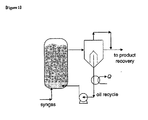
- Figure 2 schematically illustrates a continuous separation and discharge apparatus of solid catalyst and products for Fischer-Tropsch synthesis reactions according to the present invention.
- a level sensor 10 and thermocouples 11 detecting the level of reactants are disposed at an upper portion of a slurry bubble column reactor 12, and a solid catalyst/product (wax) separation device and a product discharge device are disposed at a lower portion of the slurry bubble column reactor 12.
- a feeding gas including CO and H 2 is injected through the lower portion of the slurry bubble column reactor 12. Then, chemical reactions between the feeding gas and the slurry-state solid catalyst 15 are conducted in the slurry bubble column reactor 12 so as to synthesize hydrocarbon such as wax as shown in Formula 1 below. Since the Fischer-Tropsch synthesis is an exothermic reaction, a cooling device is necessary.
- nCO + n + m n ⁇ H 2 ⁇ C n ⁇ H m + n ⁇ H 2 O ⁇ ⁇ H FT 0 - 165 ⁇ kJ mol
- Cobalt (Co)- and iron (Fe)-based catalysts are widely used for the Fischer-Tropsch reaction.
- Synthetic oil and wax may be synthesized in the presence of a cobalt catalyst at 200 to 260 °C at 1.0 to 3.0 MPa, and diesel and naphtha may be synthesized in the presence of an iron catalyst at 300 to 350 °C at 1.0-3.0 MPa.
- the present invention focuses on the synthesis of wax in the presence of the cobalt catalyst.
- the wax synthesized by the Fischer-Tropsch reaction may be a C 12 -C 200 hydrocarbon, and preferably a C 23 -C 48 hydrocarbon, and the number of carbon atoms may be adjusted by regulating operation methods and conditions.
- An average particle size of the cobalt catalyst used in the Fischer-Tropsch reaction for slurry reaction may be in a range of about 30 to 150 ⁇ m.
- products synthesized by the Fischer-Tropsch reaction are discharged out of a reactor 1 in the form of catalyst/product mixture slurry, and transferred to a separation device 2 to obtain a final product.
- a slurry recirculation device such as a slurry pump 3, is necessary in order to re-inject the catalyst separated outside of the reactor 1 into the reactor 1.
- products may be directly discharged out of a reactor 12 using a catalyst/product separation device disposed at an upper portion inside the reactor.
- wax the product of the Fischer-Tropsch synthesis
- wax having a long hydrocarbon chain has high quality, high viscosity, high specific gravity, and high boiling point.
- wax having a long hydrocarbon chain which is synthesized by the Fischer-Tropsch reaction may be efficiently obtained according to the present invention since the separation/discharge device is disposed at the lower portion of the slurry bubble column reactor 12.
- the level of the slurry-state reactants is increased by the amount of the products synthesized by the Fischer-Tropsch synthesis as the Fischer-Tropsch synthesis progresses in the slurry bubble column reactor 12.
- the level of the reactants in the slurry bubble column reactor 12 is detected by the level sensor 10 or thermocouples 11 disposed at the upper portion of the slurry bubble column reactor 12.
- a drive unit 17 for discharging products disposed at the lower portion of the slurry bubble column reactor 12, receives a signal from the level sensor and opens a product discharge fluid flow control valve 18 to discharge the products until the level of the reactants reaches a predetermined low level.
- solid catalysts 15 are filtered by a metal sintering filter 24 disposed at the lower portion of the slurry bubble column reactor 12, and liquid products are discharged out of the slurry bubble column reactor 12.
- the drive unit 17 receives a signal from the level sensor and closes the product discharge fluid flow control valve 18.
- the level of the reactants in the slurry bubble column reactor 12 is increased to the high level by the synthesized products.
- the product discharge fluid flow control valve 18 is opened by the signal received from the level sensor 10 or the thermocouples 11 to discharge a predetermined amount of the products out of the slurry bubble column reactor 12.
- the level of the reactants in the slurry bubble column reactor 12 and the concentration of the slurry may be constantly maintained to have uniform working conditions, thereby obtaining high purity products.
- Radar type or ultrasonic wave type high-temperature and high-pressure level sensors 10 and thermocouples 11 may be used as a level sensing device. While the slurry-phase reactants do not have temperature gradient along the axial direction in a SBCR, the slurry-phase reactants and gas-phase space filled with tail gases have a temperature difference ranging from 10 to 30°C in the Fischer-Tropsch reaction. Thus, the thermocouples 11 may be used as level sensing devices.
- thermocouples 11 which can transmit output signals may be more efficiently used in the slurry bubble column reactor 12 compared to the level sensor 10.
- a solid catalyst/product separation device may be a metal sintering filter 24 having a pore size of about 5 to about 15 ⁇ m and standing high temperature and high pressure. If the pore size of the metal sintering filter 24 is too small, significant pressure drops occur at upper and lower portions of the metal sintering filter 24 to reduce the separation rate of the catalyst and wax. On the other hand, if pore size of the metal sintering filter 24 is too large, finely abraded catalyst cannot be efficiently separated. Thus, metal sintering filter 24 may have a pore size of about 5 to about 15 ⁇ m.
- electronic differential pressure sensors 20 are installed at the upper and lower portions of the metal sintering filter 24.
- the pressure drops occurring at the upper or lower portion of the metal sintering filter 24 may be detected by the electronic differential pressure sensors 20 disposed at the upper and lower portions of the metal sintering filter 24.
- a control unit 16 receives the detected signal and transmits a control signal to a drive unit 21. Then, the drive unit 21 controls a gas injection fluid flow control valve 22.
- the product discharge fluid flow control valve 18 is closed by the detected signal so that the products are not discharged.
- Periodic gas pulses using a feeding gas are provided to the metal sintering filter so that pressure drops increasingly occurring at the upper and lower portions of the metal sintering filter 24 return to an initial state. Accordingly, the continuous slurry separation and product discharge may be restored back to the initial state.
- the drive units 17 and 21 are devices providing driving forces so as to open and close the fluid flow control valves 18 and 22, and may be configured by a gear and motor assembly or a hydraulic piston and cylinder assembly.
- the gas used for the gas pulse of the metal sintering filter 24 may be a feeding gas of the Fischer-Tropsch reaction.
- the gas is transferred into the slurry bubble column reactor 12 after being used for the gas pulse and used as the feeding gas of the Fischer-Tropsch reaction.
- a product buffer tank 19 may be used in order to smoothly discharge the products since the Fischer-Tropsch synthesis is performed at high temperature and high pressure.
- Figure 3 illustrates a plan view and a front view of a cartridge type solid catalyst/wax separation device.
- the metal sintering filter used herein may be a planar filter 24 or a cartridge type filter 25 shown in Figure 3 .
- a planar metal sintering filter 24 may be used in a laboratory scale or bench scale slurry bubble column reactor 12, and a cartridge-shape metal sintering filter 25, which has a wide separation area using a plurality of cartridge units, may be used in a pilot scale slurry bubble column reactor 12 or a greater reactor.
- the solid catalyst/wax separation rate may be increased and the lifetime of the gas injection fluid flow control valve 22 may be prolonged by delaying the cycle of the gas pulse using the cartridge type filter 25.
- Figures 4a and 4b illustrate gas distributors (or spargers) 23.
- Figure 4a is a multi-row tube type gas distributor
- Figure 4b is a spider type gas distributor.
- the gas distributor 23 can uniformly inject the feeding gas into the slurry bubble column reactor 12. In addition, the contact between the solid catalyst/product mixture and the metal sintering filter 24 should not be interfered. Thus, a multi-nozzle tube type 27 ( Figure 4a ) or multi-nozzle spider type 27 ( Figure 4b ) may be preferably used for the gas distributor 23 rather than a perforated plate type having holes with a predetermined size.
- the gas distributor 23 may be disposed on the metal sintering filter 24.
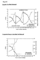
- Figure 5 illustrates pressure drops applied to a metal sintering filter and rates of product (wax) discharge according to the number of times of the solid catalyst/wax separation and discharge, in a Fischer-Tropsch synthesis reactor having a diameter of 0.05 m and a height of 1.5 m (220 °C, 20 bar) according to Example 1 and Comparative Example 1.
- the pressure drop occurring at the upper and lower portions of the metal sintering filter is increased as the number of times of the solid catalyst/wax separation and discharge is increased as shown in Figure 5 (Example 1 (gas pulse)). As the pressure drop is increased, the rate of wax discharge is decreased.
- the pressure drop and the rate of wax discharge return to the initial state by performing the gas pulse for 2 minutes.
- the pressure drop is increased, thereby decreasing the rate of wax discharge to about 0.01 l / cm 2 / min.
- the pressure drop and the rate of wax discharge return to a state more excellent than the initial state by performing the gas pulse for 10 minutes.
- the solid catalyst/wax separation device may be operated in optimized conditions.
- Figure 6 illustrates pressure drops applied to a metal sintering filter and rates of product discharge according to a gas pulse time in a Fischer-Tropsch synthesis reactor.
- the pressure drops applied to the metal sintering filter are decreased as the gas pulse time is increased to increase the rate of wax discharge. It can be seen that the rate of wax discharge reaches the highest value after 10 minutes and is constantly maintained thereafter.
- the back-flushing of the metal sintering filter of the Fischer-Tropsch reactor having a diameter of 5 cm is optimized by performing the gas pulse for 10 minutes after 8 times of the solid catalyst/wax separations and discharges.
- the back-flushing is automatically performed by the level sensor 10, the differential pressure sensor 20, and the catalyst/wax separation device when 7 bar of pressure drop is detected at the upper and lower portions of the metal sintering filter, thereby continuously performing the Fischer-Tropsch reaction in optimized conditions.
- Figure 7 schematically illustrates a bench scale (0.1 barrel/ day) Fischer-Tropsch synthesis reactor 12 according to the present invention.
- a hydro-cyclone as a solid catalyst/wax separation device, and a high-temperature and high-pressure slurry pump, as a slurry recirculation device, which are essential for a conventional slurry bubble column reactor for Fischer-Tropsch reactions, are not necessary.
- high-quality long-chain hydrocarbon products are continuously obtained while maintaining uniform operation conditions by discharging synthesized wax through the lower portion of the slurry bubble column reactor 12. Further, efficiency decrease of the FT reactor due to the abrasion of catalyst can be inhibited.
Description
- The present invention relates to an apparatus and method for continuous separation and discharge of liquid products and solid catalysts for Fischer-Tropsch synthesis reactions, and more particularly, to a continuous separation and discharge apparatus and method of solid catalysts and liquid products for Fischer-Tropsch synthesis reactions involving the conversion of synthetic gas into synthetic oil, by which products of the Fischer-Tropsch synthesis including wax, as a long-chain hydrocarbon, can be stably obtained by continuously separating the products from a slurry comprising solid catalyst particles and the products using periodic pulses of a feeding gas and discharging the liquid products through a lower portion of a reactor.
- Recently, with the recent rapid increase in oil price, much attention has been paid to gas to liquid (GTL) processes using natural gases instead of petroleum as fuels for transportation or raw materials in the petrochemical industry. In fact, the researches on Fischer-Tropsch synthesis, a carbon monoxide hydrogenation, had not been active until early 1970s, but with the recent increase in oil price, Fischer-Tropsch method is gaining again much attention.
- Of the techniques involved in the GTL process, which have various techniques including those for reforming and purifying synthetic gases, the Fischer-Tropsch synthesis reaction, by which synthetic hydrocarbon is synthesized from a synthetic gas, is considered a core technique.
- Various products may be synthesized according to the composition of synthetic gas and a catalyst used in the Fischer-Tropsch synthesis process to produce synthetic oil from synthetic gas (CO+H2).
- In general, if a synthetic gas having a H2/CO ratio of 2 or higher is used for the Fischer-Tropsch synthesis process, a large amount of heavy hydrocarbon products is synthesized. On the other hand, if synthetic gas having a H2/CO ratio of less than 2 is used for the Fischer-Tropsch synthesis process, gasoline (C5-C11), diesel (C12-C18), wax (>C24), or the like are synthesized.
- Fe-based and Co-based Fischer-Tropsch catalysts are used in an industrial scale according to the H2/CO ratio.
- Further, various chemical products such as hydrocarbon, alcohol, ether, and acetic acid can be synthesized by varying synthetic conditions.
-
U.S. Patent No. 5,543,437A (Charles B. Benham, Arvada ) andWO 2005/090521 (CompactGTL plc, Mike Bowe, Joseph ) disclose a process for the production of long-chain hydrocarbons, such as synthetic oil, from natural gas. - In general, reactors for Fischer-Tropsch synthesis can be classified into fixed bed reactors (FBR), slurry bubble column reactors (SBCR), and fuidized bed reactors. At present, the fixed bed reactors and the slurry bubble column reactors are widely used.
- The slurry bubble column reactor is more advantageous than the fixed bed reactor as a pilot-scale reactor for Fischer-Tropsch synthesis as follows.
- The slurry bubble column reactor:
- 1) has high efficiency of heat transfer,
- 2) has no pressure drop and no temperature gradient along an axial direction of the reactor (i.e., no hot spot),
- 3) can add, discharge, and restore a catalyst during the operation,
- 4) can be easily installed,
- 5) can be installed in a cost-effective manner,
- 6) has high yield (the amount of products per reactor volume), and
- 7) has a large capacity of reactor.
- Based on these advantages, slurry bubble column reactors are more widely used than the fixed bed reactors. However, slurry bubble column reactors require a slurry recirculation device and a separator which separates solid catalysts and liquid products from the slurry.
- In addition, since catalyst particles in the slurry bubble column reactor are attrited to finer particles with a lapse of time during the operation, efficiencies of the slurry recirculation device and the separation device are decreased so that the catalyst particles may be discharged out of the slurry bubble column reactor. Thus, products cannot be uniformly and continuously obtained since the concentration of the slurry and operation conditions in the slurry bubble column reactor are changed.
-
U.S. Patent No. 5,599,849A (Berend Jager ) discloses a back flush process upon the slurry separator in a slurry bubble column reactor for Fischer-Tropsch synthesis. Liquid products are continuously separated and discharged using a plurality of filtering medium units, as a slurry separation device, installed at an upper portion of the slurry bubble column reactor. When a pressure drop of equal to or grater than 8 bar is detected in the slurry separation device, the slurry separation device is restored to an initial state using a back flush of liquid products and high pressure gases. - However, according to the above patent, pressure loss applied to the slurry separation device is increased with a lapse of time during the operation. Accordingly, pressure in the reactor is increased to increase the level of reactants, and thus the concentration of the slurry is decreased. Theses change in operation conditions cannot induce a uniform Fischer-Tropsch synthesis reaction. Furthermore, the products and the high pressure gases, which are media of the back flush process, further increase the pressure in the reactor, thereby interfering with regular operations.
- Further, a short-chain hydrocarbon instead of the desired long-chain hydrocarbon may be obtained since the separation device and the product discharge device are disposed at an upper portion of the reactor since the desired products of the Fischer-Tropsch reaction may be positioned at the lower portion of the reactor due to increased viscosity and specific gravity with the growth of the chain.
-
U.S. Patent No. 5,422,375A (Erling Rytter) discloses a method of continuously separating and discharging slurry in a reactor for Fischer-Tropsch synthesis by installing a slurry separation device for pressure fluctuations in the reactor and sensing a vacuum state in the slurry separation device when the level of reactants is increased. - However, the method is not practical, and has a disadvantage that the separation device cannot be easily repaired once it becomes defective.
-
U.S. Patent No. 7,144,924 B2 (Gabriele Carlo Ettore Clerici ) discloses a hydro-cyclone for separating slurry. The efficiency of the hydro-cyclone is significantly influenced by the concentration of the slurry and catalyst particle size distribution. - Unfortunately, however, since catalyst particles in the slurry bubble column reactor are abraded with a lapse of time during the operation, the hydro-cyclone may not be practical.
- Thus, there is a need to develop a Fischer-Tropsch synthesis method by which solid catalyst and product mixture slurry is continuously separated and high-quality long-chain hydrocarbon products are uniformly discharged by the amount of the synthesized products in the slurry bubble column reactor for Fischer-Tropsch synthesis.
- [Reference No. 1]
US 5543437 A (Charles B. Benham, Arvada) 1996.08.06 - [Reference No. 2]
WO 2005/090521 (CompactGTL plc, Mike Bowe, Joseph) 2005.09.29 - [Reference No. 3]
US 5599849 A (Berend Jager) 1997.02.04 - [Reference No. 4]
US 5422375 A (Erling Rytter) 1995.06.06 - [Reference No. 5]
US 7144924 B2 (Gabriele Carlo Ettore Clerici) 2006.12.06 - The present invention provides an apparatus and method for continuous separation and discharge of liquid products and solid catalysts for Fischer-Tropsch synthesis reactions by which long-chain hydrocarbon synthetic oil is continuously synthesized under stable operation conditions by continuously separating solid catalysts and liquid products mixture slurry and uniformly maintaining the concentration of the slurry in a reactor by discharging the products by the amount of the synthesized products.
- The present invention also provides an apparatus and method for continuous separation and discharge of solid catalysts and liquid products for Fischer-Tropsch synthesis reactions by which reaction is uniformly maintained by restoring separation efficiency of a slurry separation device to an initial state without changing reaction conditions when a pressure drop is increased in the slurry separation device and separation efficiency is decreased.
- According to an aspect of the present invention, there is provided a continuous separation and discharge apparatus of solid catalysts and liquid products for Fischer-Tropsch synthesis reactions by which synthetic oil is synthesized from a feeding gas, the apparatus including: a level sensing device which is installed at an inner portion of a reactor and detects the level of reactants; a solid catalyst/liquid product separation device and a discharge device which are installed at a lower portion of the reactor and separate and discharge solid catalysts and products mixed in the reactor; a control unit which receives a signal from the level sensing device to open and close the discharge device, wherein the separation device filters the solid catalysts, and the discharge device continuously discharges the liquid products separated from the solid catalysts through the lower portion of the reactor by the amount of the synthesized products measured by a slurry level sensing device;
differential pressure sensors which are installed at upper and lower portions of the separation device and detect a pressure drop occurring at the upper and lower portions of the separation device; and a filter restoration device which provides periodic gas pulses to the separation device using a feeding gas to restore the separation device, to which the solid catalysts are fused or deposited, back to an initial state, wherein the control unit receives a signal from the differential pressure sensor to control operation of the filter restoration device when the pressure drop is increased to a predetermined level. - The level sensing device may include one of a radar type or ultrasonic wave type level sensor and a thermocouple, or both of the level sensor and the thermocouple, wherein the thermocouple detects the level of reactants by the temperature difference between the slurry-state reactants and space filled with gases.
- The separation device may be a filter for separating solid catalysts and products having a uniform pore size.
- The separation device may be a planar filter or a cartridge type filter having a relatively larger separation area compared to the planar filter.
- The discharge device may include an outlet disposed at a lower portion of the reactor, a product discharge fluid flow control valve, which opens and closes the outlet, and a drive unit controlling the opening and closing operations of the fluid flow control valve, wherein the drive unit is a motor or a cylinder.
- The filter restoration device may include a gas distributor having a plurality of nozzles, a gas injection fluid flow control valve supplying the feeding gas to the gas distributor, and a drive unit controlling the opening and closing operations of the gas injection fluid flow control valve, for uniformly injecting the feeding gas into the reactor and not inhibiting the solid catalyst/product mixture from being injected into the separation device, wherein the drive unit is a motor or a cylinder.
- The gas distributor may include a tubular cylinder in which a gas flows, wherein a plurality of rows of the tubular cylinder are arranged in parallel or the tubular cylinder radially extends from the center.
- According to another aspect of the present invention, there is provided a method of continuously separating and discharging solid catalysts and products for Fischer-Tropsch synthesis reactions, the method including: measuring a level of reactants according to the progress of the reaction using a level sensing device; filtering solid catalysts using a separation device disposed at a lower portion of a reactor and discharging products by opening a product discharge fluid flow control valve disposed at a lower portion of the separation device when the level sensing device detects that the level of reactants reaches a first standard level (high level);
closing the product discharge fluid flow control valve when the level sensing device detects that the level of the reactants reaches a second standard level (low level) as the level of the reactants is decreased by discharging the products using the product discharge fluid flow control valve;
detecting a pressure drop occurring by the increased amount of the solid catalysts fused to and deposited on the separation device as the number of discharge of the product discharge fluid flow control valve is increased, using differential pressure sensors installed at upper and lower portions of the reactor; and removing the deposited solid catalysts by providing a feeding gas to the separation device if a pressure drop is greater than a predetermined level based on a signal received from the differential pressure sensors. - As described above, according to the continuous separation and discharge apparatus and method of solid catalysts and products for Fischer-Tropsch synthesis reactions, products synthesized by the Fischer-Tropsch reaction can be continuously obtained by uniformly maintaining the level of reactants using a level sensing device, and continuously separating and discharging the products through a lower portion of a reactor using product separation and discharge devices installed at a lower portion of the reactor.
- In addition, a filter for separating the products is restored to an initial state by providing periodic gas pulses thereto so that the products can be continuously prepared for a long period of time using separation, discharge, and periodic restoration processes.
- Further, since a hydro-cyclone and a slurry recirculation device, which are essential for a conventional slurry bubble column reactor for Fischer-Tropsch reactions, are not necessary, a Fischer-Tropsch (FT) reactor can be simply manufactured and easily operated, and efficiency decrease of the FT reactor due to the abrasion of catalysts can be inhibited.
-
-
Figure 1 schematically illustrates a conventional slurry bubble column reactor for Fischer-Tropsch synthesis. -
Figure 2 schematically illustrates a slurry bubble column reactor for Fischer-Tropsch synthesis according to the present invention. -
Figure 3 illustrates a plan view and a front view of a cartridge type solid catalyst/wax separation device. -
Figures 4A and 4B respectively illustrate a plan view and a front view of a gas distributor. -
Figure 5 illustrates pressure drops applied to a separation device and rates of product discharge according to the number of times of product discharge. -
Figure 6 illustrates pressure drops applied to a separation device and rates of product discharge according to a gas pulse time. -
Figure 7 schematically illustrates a bench scale Fischer-Tropsch synthesis reactor according to the present invention. -
- 10: a level sensor 11: thermocouples
- 12: a slurry bubble column reactor 15: a slurry-state solid catalyst
- 16: a control unit 17: a drive unit for product discharge
- 18: a product discharge fluid flow control valve
- 19: a product buffer tank 20: electronic differential pressure sensors
- 21: a drive unit for gas injection 22: gas injection fluid flow control valve
- 23: a gas distributor 24: solid catalyst/product mixture and metal sintering filter
- 25: a cartridge type filter 26: metal seal
- 27: nozzle
- Hereinafter, the present invention will be described in more detail with reference to the accompanying drawings, in which exemplary embodiments of the invention are shown.
-
Figure 2 schematically illustrates a continuous separation and discharge apparatus of solid catalyst and products for Fischer-Tropsch synthesis reactions according to the present invention. - Referring to
Figure 2 , alevel sensor 10 andthermocouples 11 detecting the level of reactants are disposed at an upper portion of a slurrybubble column reactor 12, and a solid catalyst/product (wax) separation device and a product discharge device are disposed at a lower portion of the slurrybubble column reactor 12. - In general, in the slurry
bubble column reactor 12 for Fischer-Tropsch synthesis, a feeding gas including CO and H2 is injected through the lower portion of the slurrybubble column reactor 12. Then, chemical reactions between the feeding gas and the slurry-statesolid catalyst 15 are conducted in the slurrybubble column reactor 12 so as to synthesize hydrocarbon such as wax as shown inFormula 1 below. Since the Fischer-Tropsch synthesis is an exothermic reaction, a cooling device is necessary.
- Cobalt (Co)- and iron (Fe)-based catalysts are widely used for the Fischer-Tropsch reaction. Synthetic oil and wax may be synthesized in the presence of a cobalt catalyst at 200 to 260 °C at 1.0 to 3.0 MPa, and diesel and naphtha may be synthesized in the presence of an iron catalyst at 300 to 350 °C at 1.0-3.0 MPa.
- The present invention focuses on the synthesis of wax in the presence of the cobalt catalyst. The wax synthesized by the Fischer-Tropsch reaction may be a C12-C200 hydrocarbon, and preferably a C23-C48 hydrocarbon, and the number of carbon atoms may be adjusted by regulating operation methods and conditions. An average particle size of the cobalt catalyst used in the Fischer-Tropsch reaction for slurry reaction may be in a range of about 30 to 150 µm.
- In general, products synthesized by the Fischer-Tropsch reaction are discharged out of a
reactor 1 in the form of catalyst/product mixture slurry, and transferred to aseparation device 2 to obtain a final product. As shown inFigure 1 , a slurry recirculation device, such as aslurry pump 3, is necessary in order to re-inject the catalyst separated outside of thereactor 1 into thereactor 1. - As shown in
U.S. Patent No. 5,599,849A (Berend Jager ), products may be directly discharged out of areactor 12 using a catalyst/product separation device disposed at an upper portion inside the reactor. - As described above, the products synthesized in a conventional bubble column reactor for the Fischer-Tropsch synthesis are discharged through the upper portion of the reactor. However, wax, the product of the Fischer-Tropsch synthesis, may be located at the lower portion of the reactor since wax having a long hydrocarbon chain has high quality, high viscosity, high specific gravity, and high boiling point.
- As shown in
Figure 2 , wax having a long hydrocarbon chain which is synthesized by the Fischer-Tropsch reaction may be efficiently obtained according to the present invention since the separation/discharge device is disposed at the lower portion of the slurrybubble column reactor 12. - The level of the slurry-state reactants is increased by the amount of the products synthesized by the Fischer-Tropsch synthesis as the Fischer-Tropsch synthesis progresses in the slurry
bubble column reactor 12. The level of the reactants in the slurrybubble column reactor 12 is detected by thelevel sensor 10 orthermocouples 11 disposed at the upper portion of the slurrybubble column reactor 12. When the level of the reactants reaches a predetermined high level, adrive unit 17 for discharging products, disposed at the lower portion of the slurrybubble column reactor 12, receives a signal from the level sensor and opens a product discharge fluidflow control valve 18 to discharge the products until the level of the reactants reaches a predetermined low level. - In this regard, among the slurry-state reactants,
solid catalysts 15 are filtered by ametal sintering filter 24 disposed at the lower portion of the slurrybubble column reactor 12, and liquid products are discharged out of the slurrybubble column reactor 12. When the level of the reactants reaches the low level, thedrive unit 17 receives a signal from the level sensor and closes the product discharge fluidflow control valve 18. Thus, the level of the reactants in the slurrybubble column reactor 12 is increased to the high level by the synthesized products. - This process is repeated. Accordingly, the product discharge fluid
flow control valve 18 is opened by the signal received from thelevel sensor 10 or thethermocouples 11 to discharge a predetermined amount of the products out of the slurrybubble column reactor 12. Thus, the level of the reactants in the slurrybubble column reactor 12 and the concentration of the slurry may be constantly maintained to have uniform working conditions, thereby obtaining high purity products. - Radar type or ultrasonic wave type high-temperature and high-
pressure level sensors 10 andthermocouples 11 may be used as a level sensing device. While the slurry-phase reactants do not have temperature gradient along the axial direction in a SBCR, the slurry-phase reactants and gas-phase space filled with tail gases have a temperature difference ranging from 10 to 30°C in the Fischer-Tropsch reaction. Thus, thethermocouples 11 may be used as level sensing devices. - In particular, if the
level sensor 10 cannot be installed in a small-sized slurrybubble column reactor 12 or thelevel sensor 10 has frequent defects, thethermocouples 11 which can transmit output signals may be more efficiently used in the slurrybubble column reactor 12 compared to thelevel sensor 10. - In addition, a solid catalyst/product separation device may be a
metal sintering filter 24 having a pore size of about 5 to about 15 µm and standing high temperature and high pressure. If the pore size of themetal sintering filter 24 is too small, significant pressure drops occur at upper and lower portions of themetal sintering filter 24 to reduce the separation rate of the catalyst and wax. On the other hand, if pore size of themetal sintering filter 24 is too large, finely abraded catalyst cannot be efficiently separated. Thus,metal sintering filter 24 may have a pore size of about 5 to about 15 µm. - During the continuous slurry separation and product discharge, if catalyst particles are fused to or deposited on micro pores of the
metal sintering filter 24, as a slurry separation device, and inhibit the products from being smoothly separated and discharged, pressure drops are increased at the upper and lower portions of themetal sintering filter 24. - In order to solve theses problems, electronic
differential pressure sensors 20 are installed at the upper and lower portions of themetal sintering filter 24. The pressure drops occurring at the upper or lower portion of themetal sintering filter 24 may be detected by the electronicdifferential pressure sensors 20 disposed at the upper and lower portions of themetal sintering filter 24. Acontrol unit 16 receives the detected signal and transmits a control signal to adrive unit 21. Then, thedrive unit 21 controls a gas injection fluidflow control valve 22. - The product discharge fluid
flow control valve 18 is closed by the detected signal so that the products are not discharged. The gas injection fluidflow control valve 22, which is disposed at the side of the slurrybubble column reactor 12, is opened toward a pipe for discharging the products at the lower portion of the slurrybubble column reactor 12. Periodic gas pulses using a feeding gas are provided to the metal sintering filter so that pressure drops increasingly occurring at the upper and lower portions of themetal sintering filter 24 return to an initial state. Accordingly, the continuous slurry separation and product discharge may be restored back to the initial state. - In this regard, the
drive units flow control valves - In addition, the gas used for the gas pulse of the
metal sintering filter 24 may be a feeding gas of the Fischer-Tropsch reaction. The gas is transferred into the slurrybubble column reactor 12 after being used for the gas pulse and used as the feeding gas of the Fischer-Tropsch reaction. - According to a back-flushing of the
metal sintering filter 24 using the feeding gas, conditions for the Fischer-Tropsch reaction are not changed during the back-flushing process. - A
product buffer tank 19 may be used in order to smoothly discharge the products since the Fischer-Tropsch synthesis is performed at high temperature and high pressure. -
Figure 3 illustrates a plan view and a front view of a cartridge type solid catalyst/wax separation device. The metal sintering filter used herein may be aplanar filter 24 or acartridge type filter 25 shown inFigure 3 . - A planar
metal sintering filter 24 may be used in a laboratory scale or bench scale slurrybubble column reactor 12, and a cartridge-shapemetal sintering filter 25, which has a wide separation area using a plurality of cartridge units, may be used in a pilot scale slurrybubble column reactor 12 or a greater reactor. - Since the
cartridge type filter 25 has a wider separation area than theplanar filter 24, the solid catalyst/wax separation rate may be increased and the lifetime of the gas injection fluidflow control valve 22 may be prolonged by delaying the cycle of the gas pulse using thecartridge type filter 25. -
Figures 4a and 4b illustrate gas distributors (or spargers) 23.Figure 4a is a multi-row tube type gas distributor, andFigure 4b is a spider type gas distributor. - The
gas distributor 23 can uniformly inject the feeding gas into the slurrybubble column reactor 12. In addition, the contact between the solid catalyst/product mixture and themetal sintering filter 24 should not be interfered. Thus, a multi-nozzle tube type 27 (Figure 4a ) or multi-nozzle spider type 27 (Figure 4b ) may be preferably used for thegas distributor 23 rather than a perforated plate type having holes with a predetermined size. Thegas distributor 23 may be disposed on themetal sintering filter 24. - The present invention will now be described in greater detail with reference to the following examples. The following examples are for illustrative purposes only and are not intended to limit the scope of the invention.
-
Figure 5 illustrates pressure drops applied to a metal sintering filter and rates of product (wax) discharge according to the number of times of the solid catalyst/wax separation and discharge, in a Fischer-Tropsch synthesis reactor having a diameter of 0.05 m and a height of 1.5 m (220 °C, 20 bar) according to Example 1 and Comparative Example 1. - The pressure drop occurring at the upper and lower portions of the metal sintering filter is increased as the number of times of the solid catalyst/wax separation and discharge is increased as shown in
Figure 5 (Example 1 (gas pulse)). As the pressure drop is increased, the rate of wax discharge is decreased. - When the product discharge is performed 8 times and the rate of wax discharge is about 0.01 ℓ / cm2/ min (if a standard is 0.02 ℓ / cm2/ min), a gas pulse is provided to the metal sintering filter using the feeding gas.
- The pressure drop and the rate of wax discharge return to the initial state by performing the gas pulse for 2 minutes. When the product discharge is further performed 9 times, the pressure drop is increased, thereby decreasing the rate of wax discharge to about 0.01 ℓ / cm2/ min. The pressure drop and the rate of wax discharge return to a state more excellent than the initial state by performing the gas pulse for 10 minutes. By repeating the process, the solid catalyst/wax separation device may be operated in optimized conditions.
- On the other hand, if the gas pulse is not performed as shown in Comparative Example 1 of
Figure 5 , the pressure drop occurring at the upper and lower portions of the metal sintering filter is increased up to 9 bar by a fused catalyst cake when the solid catalyst/wax separation and discharge is performed more than 10 times. Thus, the wax cannot be discharged due to the rapid increase of the pressure drop. -
Figure 6 illustrates pressure drops applied to a metal sintering filter and rates of product discharge according to a gas pulse time in a Fischer-Tropsch synthesis reactor. - The pressure drops applied to the metal sintering filter are decreased as the gas pulse time is increased to increase the rate of wax discharge. It can be seen that the rate of wax discharge reaches the highest value after 10 minutes and is constantly maintained thereafter.
- Referring to
Figures 5 and6 , the back-flushing of the metal sintering filter of the Fischer-Tropsch reactor having a diameter of 5 cm is optimized by performing the gas pulse for 10 minutes after 8 times of the solid catalyst/wax separations and discharges. The back-flushing is automatically performed by thelevel sensor 10, thedifferential pressure sensor 20, and the catalyst/wax separation device when 7 bar of pressure drop is detected at the upper and lower portions of the metal sintering filter, thereby continuously performing the Fischer-Tropsch reaction in optimized conditions. -
Figure 7 schematically illustrates a bench scale (0.1 barrel/ day) Fischer-Tropsch synthesis reactor 12 according to the present invention. - According to the present invention, a hydro-cyclone, as a solid catalyst/wax separation device, and a high-temperature and high-pressure slurry pump, as a slurry recirculation device, which are essential for a conventional slurry bubble column reactor for Fischer-Tropsch reactions, are not necessary. In addition, high-quality long-chain hydrocarbon products are continuously obtained while maintaining uniform operation conditions by discharging synthesized wax through the lower portion of the slurry
bubble column reactor 12. Further, efficiency decrease of the FT reactor due to the abrasion of catalyst can be inhibited.
Claims (10)
- An apparatus for continuous separation and discharge of solid catalysts and liquid products for Fischer-Tropsch synthesis reactions by which synthetic oil is synthesized from a feeding gas, the apparatus comprising:a level sensing device which is installed at an inner portion of a reactor and detects the level of slurry-phase reactants;a solid catalyst/liquid product separation device and a discharge device which are installed at a lower portion of the reactor and separate and discharge solid catalysts and liquid products mixed in the reactor;a control unit which receives a signal from the slurry-level sensing device to open and close the discharge device;wherein the separation device filters the solid catalysts, and the discharge device continuously discharges the liquid products separated from the solid catalysts through the lower portion of the reactor by the amount of the synthesized products measured by a slurry level sensing device;differential pressure sensors which are installed at upper and lower portions of the separation device and detect a pressure drop occurring at the upper and lower portions of the separation device; anda filter restoration device which provides periodic gas pulses to the separation device using a feeding gas to restore the separation device, to which the solid catalysts are fused or deposited, back-flushed to an initial state,wherein the control unit receives a signal from the differential pressure sensor to control operation of the filter restoration device when the pressure drop is increased to a predetermined level.
- The apparatus for continuous separation and discharge of solid catalysts and products for Fischer-Tropsch synthesis reactions of claim 1, wherein the level sensing device comprises one of a radar type or ultrasonic wave type level sensor and a thermocouple, or both of the level sensor and the thermocouple, wherein the thermocouple detects the slurry-level of reactants by the temperature difference between the slurry-phase reactants and gas-phase space filled with tail gases.
- The apparatus for continuous separation and discharge of solid catalysts and products for Fischer-Tropsch synthesis reactions of claim 2, wherein the separation device is a filter for separating solid catalysts and liquid products having a uniform pore size.
- The apparatus for continuous separation and discharge of solid catalysts and products for Fischer-Tropsch synthesis reactions of claim 3, wherein the separation device is a planar filter or a cartridge type filter having a relatively larger separation area compared to the planar filter.
- The apparatus for continuous separation and discharge of solid catalysts and products for Fischer-Tropsch synthesis reactions of claim 4, wherein the discharge device comprises an outlet disposed at a lower portion of the reactor, a product discharge fluid flow control valve, which opens and closes the outlet, and a drive unit controlling the opening and closing operations of the fluid flow control valve, wherein the drive unit is a motor or a cylinder.
- The apparatus for continuous separation and discharge of solid catalysts and products for Fischer-Tropsch synthesis reactions of claim 1, wherein the filter restoration device comprises a gas distributor having a plurality of nozzles, a gas injection fluid flow control valve supplying the feeding gas to the gas distributor, and a drive unit controlling the opening and closing operations of the gas injection fluid flow control valve, for uniformly injecting the feeding gas into the reactor and not inhibiting the solid catalyst/product mixture from being injected into the separation device, wherein the drive unit is a motor or a cylinder.
- The apparatus for continuous separation and discharge of solid catalysts and products for Fischer-Tropsch synthesis reactions of claim 6, wherein the gas distributor comprises a tubular cylinder in which a gas flows, wherein a plurality of rows of the tubular cylinder are arranged in parallel or the tubular cylinder radially extends from the center.
- A method for continuous separation and discharge of solid catalysts and products for Fischer-Tropsch synthesis reactions, the method comprising:measuring a slurry-level of reactants according to the progress of the reaction using a level sensing device;filtering solid catalysts using a separation device disposed at a lower portion of a reactor and discharging liquid products by opening a product discharge fluid flow control valve disposed at a lower portion of the separation device when the level sensing device detects that the level of reactants reaches a first standard level (high level);closing the product discharge fluid flow control valve when the level sensing device detects that the level of the reactants reaches a second standard level (low level) as the level of the reactants is decreased by discharging the products using the product discharge fluid flow control valve;detecting a pressure drop occurring by the increased amount of the solid catalysts fused to and deposited on the separation device as the number of discharge of the product discharge fluid flow control valve is increased, using differential pressure sensors installed at upper and lower portions of the reactor;andremoving the deposited solid catalysts by providing a feeding gas to the separation device if a pressure drop is greater than a predetermined level based on a signal received from the differential pressure sensors.
- The method of claim 8, wherein the separation device, which is a planar filter or a cartridge type filter having a relatively larger separation area compared to the planar filter, is a filter for separating solid catalysts and products having micro pores with a uniform pore size.
- The method of claim 9, wherein the filter restoration device comprises a gas distributor having a plurality of nozzles, a gas injection fluid flow control valve supplying the feeding gas to the gas distributor, and a drive unit controlling the opening and closing operations of the gas injection fluid flow control valve, for uniformly injecting the feeding gas into the reactor and not inhibiting the solid catalyst/liquid product mixture from being injected into the separation device, wherein the drive unit is a motor or a cylinder.
Applications Claiming Priority (2)
| Application Number | Priority Date | Filing Date | Title |
|---|---|---|---|
| KR1020080018679A KR100992835B1 (en) | 2008-02-29 | 2008-02-29 | The continuous separation and discharge apparatus and method of solid catalysts and product product for Fischer-Tropsch synthesis reactions |
| PCT/KR2008/007250 WO2009107927A1 (en) | 2008-02-29 | 2008-12-08 | Method and apparatus for the continuous seperation and discharge of solid catalysts and products for fischer-tropsch synthesis reactions |
Publications (3)
| Publication Number | Publication Date |
|---|---|
| EP2249945A1 EP2249945A1 (en) | 2010-11-17 |
| EP2249945A4 EP2249945A4 (en) | 2011-12-14 |
| EP2249945B1 true EP2249945B1 (en) | 2015-09-23 |
Family
ID=41016280
Family Applications (1)
| Application Number | Title | Priority Date | Filing Date |
|---|---|---|---|
| EP08872812.6A Not-in-force EP2249945B1 (en) | 2008-02-29 | 2008-12-08 | Method and apparatus for the continuous separation and discharge of solid catalysts and products for fischer-tropsch synthesis reactions |
Country Status (7)
| Country | Link |
|---|---|
| US (1) | US8852516B2 (en) |
| EP (1) | EP2249945B1 (en) |
| JP (1) | JP5647524B2 (en) |
| KR (1) | KR100992835B1 (en) |
| CN (1) | CN101959575B (en) |
| AU (1) | AU2008351486B2 (en) |
| WO (1) | WO2009107927A1 (en) |
Families Citing this family (13)
| Publication number | Priority date | Publication date | Assignee | Title |
|---|---|---|---|---|
| JP5675146B2 (en) * | 2010-03-30 | 2015-02-25 | 独立行政法人石油天然ガス・金属鉱物資源機構 | Process for producing hydrocarbons |
| US9243988B2 (en) | 2010-07-08 | 2016-01-26 | Exxonmobil Chemical Patents Inc. | System and method for monitoring bubble formation within a reactor |
| US9296833B2 (en) | 2010-07-08 | 2016-03-29 | Exxonmobil Chemical Patents Inc. | Method for controlling bubble formation in polymerization reactors |
| KR101210397B1 (en) * | 2010-09-17 | 2012-12-10 | 한국화학연구원 | Catalyst/Wax separation device in a slurry phase Fischer-Tropsch synthesis reactor system |
| US9849434B2 (en) * | 2010-09-22 | 2017-12-26 | Grupo Petrotemex, S.A. De C.V. | Methods and apparatus for enhanced gas distribution |
| US9545622B2 (en) | 2010-10-11 | 2017-01-17 | Exxonmobil Chemical Patents Inc. | Activation and use of hydroalkylation catalysts |
| JP5703096B2 (en) | 2011-03-31 | 2015-04-15 | 独立行政法人石油天然ガス・金属鉱物資源機構 | Method for estimating content of fine particles in slurry and method for producing hydrocarbon oil |
| JP5808559B2 (en) | 2011-03-31 | 2015-11-10 | 独立行政法人石油天然ガス・金属鉱物資源機構 | Hydrocarbon oil production method, Fischer-Tropsch synthesis reactor, and hydrocarbon oil production system |
| CN103182221B (en) * | 2011-12-29 | 2017-03-01 | Cap Iii 有限公司 | The method separating solid catalyst particle from inorganic process liquid |
| CN109762600A (en) * | 2017-11-09 | 2019-05-17 | 陕西未来能源化工有限公司 | A kind of Low Temperature Fischer Tropsch synthesis paraffin classification cycle filtration system |
| CN108465281B (en) * | 2018-05-28 | 2023-09-19 | 浙江东瓯过滤机制造有限公司 | Filtering and concentrating device and filtering and concentrating method thereof |
| CN109289712A (en) * | 2018-12-04 | 2019-02-01 | 怀化学院 | Experimental reactor |
| CN113457611B (en) * | 2021-07-06 | 2022-08-05 | 江西鑫铂瑞科技有限公司 | Electrolytic copper foil copper dissolving material process capable of reducing energy consumption |
Family Cites Families (22)
| Publication number | Priority date | Publication date | Assignee | Title |
|---|---|---|---|---|
| US3542674A (en) * | 1968-07-22 | 1970-11-24 | Owens Corning Fiberglass Corp | Method for removing solids suspensions in liquids |
| FR2385429A1 (en) * | 1977-03-28 | 1978-10-27 | Degremont | METHOD AND APPARATUS FOR SEPARATION OF EMULSIONS BY COALESCENCE |
| FR2529905B1 (en) * | 1982-07-09 | 1988-04-08 | Inst Francais Du Petrole | PROCESS AND DEVICE FOR HYDROPROCESSING HYDROCARBONS IN LIQUID PHASE, IN THE PRESENCE OF A CATALYST IN EXPANDED OR BOILING BED |
| US4487065A (en) * | 1983-03-07 | 1984-12-11 | Cypher Systems | Storage tank level monitoring apparatus and method therefor |
| EP0221209A1 (en) * | 1985-10-10 | 1987-05-13 | Mobil Oil Corporation | Multi-phase countercurrent reactor process and apparatus |
| US4550012A (en) * | 1984-05-01 | 1985-10-29 | Mobil Oil Corp. | Multi-phase countercurrent reactor system |
| US4580597A (en) * | 1985-04-15 | 1986-04-08 | Monsanto Company | Fluid distribution system |
| US5543437A (en) * | 1986-05-08 | 1996-08-06 | Rentech, Inc. | Process for the production of hydrocarbons |
| GB9203959D0 (en) * | 1992-02-25 | 1992-04-08 | Norske Stats Oljeselskap | Method of conducting catalytic converter multi-phase reaction |
| US5599849A (en) * | 1993-01-27 | 1997-02-04 | Sasol Chemical Industries (Proprietary) Limited | Process for producing liquid and, optionally, gaseous products from gaseous reactants |
| US5620607A (en) * | 1995-05-30 | 1997-04-15 | Bowie, Jr.; James E. | Filtering fluidized bed reactor |
| US5939350A (en) * | 1997-02-10 | 1999-08-17 | Energy International Corporation | Processes and catalysts for conducting fischer-tropsch synthesis in a slurry bubble column reactor |
| JPH10244135A (en) * | 1997-03-07 | 1998-09-14 | Hitachi Ltd | Back-washing method of filter, its operation, method of estimating service life of filter element, and regeneration of filter element |
| ZA985992B (en) | 1997-07-15 | 2000-01-10 | Sasol Tech Pty Ltd | A process for producing liquid and, optionally, gaseous products from gaseous reactants. |
| ITMI980865A1 (en) * | 1998-04-23 | 1999-10-23 | Eniricerche S P A Ora Enitecno | PROCEDURE FOR THE PREPARATION OF HYDROCARBONS FROM SYNTHESIS GAS |
| ITMI20030969A1 (en) * | 2003-05-15 | 2004-11-16 | Enitecnologie Spa | PROCEDURE FOR THE CONTINUOUS PRODUCTION OF HYDROCARBONS FROM SYNTHESIS GAS IN SUSPENSION REACTORS AND FOR THE SEPARATION OF THE LIQUID PHASE PRODUCED FROM THE SOLID PHASE. |
| ITMI20031288A1 (en) * | 2003-06-25 | 2004-12-26 | Enitecnologie Spa | PROCESS FOR THE CONTINUOUS PRODUCTION OF HYDROCARBONS FROM SYNTHESIS GAS IN SUSPENSION REACTORS AND FOR THE SEPARATION OF THE LIQUID PHASE PRODUCED FROM THE SOLID PHASE. |
| CA2532513A1 (en) * | 2003-07-15 | 2005-01-20 | Sasol Technology (Proprietary) Limited | Process for separating a catalyst from a liquid |
| GB0405796D0 (en) | 2004-03-16 | 2004-04-21 | Accentus Plc | Converting natural gas to longer-chain hydrocarbons |
| JP2006289264A (en) | 2005-04-11 | 2006-10-26 | Mitsubishi Rayon Co Ltd | Suspension liquid phase reactor, method for exchanging solid catalyst using it and method for producing suspension liquid phase reaction product |
| JP4874660B2 (en) * | 2006-01-30 | 2012-02-15 | 新日鉄エンジニアリング株式会社 | Bubble column type hydrocarbon synthesis reactor |
| CN100575457C (en) * | 2006-10-08 | 2009-12-30 | 神华集团有限责任公司 | A kind of Fischer-Tropsch synthesis method |
-
2008
- 2008-02-29 KR KR1020080018679A patent/KR100992835B1/en active IP Right Grant
- 2008-12-08 JP JP2010548602A patent/JP5647524B2/en not_active Expired - Fee Related
- 2008-12-08 CN CN200880127628.0A patent/CN101959575B/en not_active Expired - Fee Related
- 2008-12-08 AU AU2008351486A patent/AU2008351486B2/en not_active Ceased
- 2008-12-08 US US12/919,919 patent/US8852516B2/en not_active Expired - Fee Related
- 2008-12-08 WO PCT/KR2008/007250 patent/WO2009107927A1/en active Application Filing
- 2008-12-08 EP EP08872812.6A patent/EP2249945B1/en not_active Not-in-force
Also Published As
| Publication number | Publication date |
|---|---|
| CN101959575B (en) | 2015-05-13 |
| EP2249945A1 (en) | 2010-11-17 |
| EP2249945A4 (en) | 2011-12-14 |
| US20110028574A1 (en) | 2011-02-03 |
| JP2011522900A (en) | 2011-08-04 |
| US8852516B2 (en) | 2014-10-07 |
| AU2008351486A1 (en) | 2009-09-03 |
| KR20090093249A (en) | 2009-09-02 |
| WO2009107927A1 (en) | 2009-09-03 |
| JP5647524B2 (en) | 2014-12-24 |
| KR100992835B1 (en) | 2010-11-08 |
| AU2008351486B2 (en) | 2012-08-02 |
| CN101959575A (en) | 2011-01-26 |
Similar Documents
| Publication | Publication Date | Title |
|---|---|---|
| EP2249945B1 (en) | Method and apparatus for the continuous separation and discharge of solid catalysts and products for fischer-tropsch synthesis reactions | |
| US7378452B2 (en) | Filtration system for slurry hydrocarbon synthesis process using both small and large pore filter elements | |
| AU664429B2 (en) | Catalytic multi-phase reactor | |
| CA2286241C (en) | Hydrocarbon synthesis catalyst slurry rejuvenation with gas disengagement | |
| EP2158294B1 (en) | Removal of fine particles from a fischer tropsch stream | |
| EP1940540B1 (en) | Filtration method | |
| WO2012036377A4 (en) | Reaction device for producing hydrocarbons from synthesis gas | |
| EP2607458B1 (en) | Method for producing hydrocarbon oil | |
| US10590348B2 (en) | Slurry bubble column reactor for a fischer-tropsch process | |
| WO2010045177A2 (en) | Integrated multi-step solid/liquid separation system for fischer-tropsch processes | |
| KR101185262B1 (en) | A apparatus and a method for separating the products in fischer-tropsch process |
Legal Events
| Date | Code | Title | Description |
|---|---|---|---|
| PUAI | Public reference made under article 153(3) epc to a published international application that has entered the european phase |
Free format text: ORIGINAL CODE: 0009012 |
|
| 17P | Request for examination filed |
Effective date: 20100929 |
|
| AK | Designated contracting states |
Kind code of ref document: A1 Designated state(s): AT BE BG CH CY CZ DE DK EE ES FI FR GB GR HR HU IE IS IT LI LT LU LV MC MT NL NO PL PT RO SE SI SK TR |
|
| AX | Request for extension of the european patent |
Extension state: AL BA MK RS |
|
| RIN1 | Information on inventor provided before grant (corrected) |
Inventor name: WOO, KWANG JAE Inventor name: KIM, SEUNG-MOON Inventor name: BAE, JONG-WOOK Inventor name: JUN, KI-WON Inventor name: KANG, SUK-HWAN |
|
| DAX | Request for extension of the european patent (deleted) | ||
| RAP1 | Party data changed (applicant data changed or rights of an application transferred) |
Owner name: KOREA RESEARCH INSTITUTE OF CHEMICAL TECHNOLOGY Owner name: KOREA GAS CORPORATION Owner name: SK INNOVATION CO., LTD. |
|
| A4 | Supplementary search report drawn up and despatched |
Effective date: 20111114 |
|
| RIC1 | Information provided on ipc code assigned before grant |
Ipc: C10G 2/00 20060101ALI20111108BHEP Ipc: B01J 8/00 20060101ALI20111108BHEP Ipc: B01D 53/00 20060101ALN20111108BHEP Ipc: B01J 8/22 20060101AFI20111108BHEP |
|
| 17Q | First examination report despatched |
Effective date: 20140725 |
|
| REG | Reference to a national code |
Ref country code: DE Ref legal event code: R079 Ref document number: 602008040350 Country of ref document: DE Free format text: PREVIOUS MAIN CLASS: B01D0053000000 Ipc: B01J0008220000 |
|
| GRAP | Despatch of communication of intention to grant a patent |
Free format text: ORIGINAL CODE: EPIDOSNIGR1 |
|
| RIC1 | Information provided on ipc code assigned before grant |
Ipc: B01D 53/00 20060101ALN20150330BHEP Ipc: B01J 8/00 20060101ALI20150330BHEP Ipc: C10G 2/00 20060101ALI20150330BHEP Ipc: B01J 8/22 20060101AFI20150330BHEP |
|
| INTG | Intention to grant announced |
Effective date: 20150428 |
|
| RAP1 | Party data changed (applicant data changed or rights of an application transferred) |
Owner name: KOREA GAS CORPORATION Owner name: KOREA NATIONAL OIL CORPORATION Owner name: DAELIM INDUSTRIAL CO., LTD. Owner name: HYUNDAI ENGINEERING CO., LTD Owner name: KOREA RESEARCH INSTITUTE OF CHEMICAL TECHNOLOGY Owner name: SK INNOVATION CO., LTD. |
|
| GRAS | Grant fee paid |
Free format text: ORIGINAL CODE: EPIDOSNIGR3 |
|
| GRAA | (expected) grant |
Free format text: ORIGINAL CODE: 0009210 |
|
| AK | Designated contracting states |
Kind code of ref document: B1 Designated state(s): AT BE BG CH CY CZ DE DK EE ES FI FR GB GR HR HU IE IS IT LI LT LU LV MC MT NL NO PL PT RO SE SI SK TR |
|
| REG | Reference to a national code |
Ref country code: GB Ref legal event code: FG4D |
|
| REG | Reference to a national code |
Ref country code: CH Ref legal event code: EP |
|
| REG | Reference to a national code |
Ref country code: AT Ref legal event code: REF Ref document number: 750923 Country of ref document: AT Kind code of ref document: T Effective date: 20151015 |
|
| REG | Reference to a national code |
Ref country code: IE Ref legal event code: FG4D |
|
| REG | Reference to a national code |
Ref country code: DE Ref legal event code: R096 Ref document number: 602008040350 Country of ref document: DE |
|
| REG | Reference to a national code |
Ref country code: FR Ref legal event code: PLFP Year of fee payment: 8 |
|
| REG | Reference to a national code |
Ref country code: NL Ref legal event code: MP Effective date: 20150923 |
|
| PG25 | Lapsed in a contracting state [announced via postgrant information from national office to epo] |
Ref country code: FI Free format text: LAPSE BECAUSE OF FAILURE TO SUBMIT A TRANSLATION OF THE DESCRIPTION OR TO PAY THE FEE WITHIN THE PRESCRIBED TIME-LIMIT Effective date: 20150923 Ref country code: NO Free format text: LAPSE BECAUSE OF FAILURE TO SUBMIT A TRANSLATION OF THE DESCRIPTION OR TO PAY THE FEE WITHIN THE PRESCRIBED TIME-LIMIT Effective date: 20151223 Ref country code: LV Free format text: LAPSE BECAUSE OF FAILURE TO SUBMIT A TRANSLATION OF THE DESCRIPTION OR TO PAY THE FEE WITHIN THE PRESCRIBED TIME-LIMIT Effective date: 20150923 Ref country code: GR Free format text: LAPSE BECAUSE OF FAILURE TO SUBMIT A TRANSLATION OF THE DESCRIPTION OR TO PAY THE FEE WITHIN THE PRESCRIBED TIME-LIMIT Effective date: 20151224 Ref country code: LT Free format text: LAPSE BECAUSE OF FAILURE TO SUBMIT A TRANSLATION OF THE DESCRIPTION OR TO PAY THE FEE WITHIN THE PRESCRIBED TIME-LIMIT Effective date: 20150923 |
|
| REG | Reference to a national code |
Ref country code: LT Ref legal event code: MG4D |
|
| REG | Reference to a national code |
Ref country code: AT Ref legal event code: MK05 Ref document number: 750923 Country of ref document: AT Kind code of ref document: T Effective date: 20150923 |
|
| PG25 | Lapsed in a contracting state [announced via postgrant information from national office to epo] |
Ref country code: SE Free format text: LAPSE BECAUSE OF FAILURE TO SUBMIT A TRANSLATION OF THE DESCRIPTION OR TO PAY THE FEE WITHIN THE PRESCRIBED TIME-LIMIT Effective date: 20150923 Ref country code: HR Free format text: LAPSE BECAUSE OF FAILURE TO SUBMIT A TRANSLATION OF THE DESCRIPTION OR TO PAY THE FEE WITHIN THE PRESCRIBED TIME-LIMIT Effective date: 20150923 |
|
| PG25 | Lapsed in a contracting state [announced via postgrant information from national office to epo] |
Ref country code: NL Free format text: LAPSE BECAUSE OF FAILURE TO SUBMIT A TRANSLATION OF THE DESCRIPTION OR TO PAY THE FEE WITHIN THE PRESCRIBED TIME-LIMIT Effective date: 20150923 |
|
| PG25 | Lapsed in a contracting state [announced via postgrant information from national office to epo] |
Ref country code: EE Free format text: LAPSE BECAUSE OF FAILURE TO SUBMIT A TRANSLATION OF THE DESCRIPTION OR TO PAY THE FEE WITHIN THE PRESCRIBED TIME-LIMIT Effective date: 20150923 Ref country code: IS Free format text: LAPSE BECAUSE OF FAILURE TO SUBMIT A TRANSLATION OF THE DESCRIPTION OR TO PAY THE FEE WITHIN THE PRESCRIBED TIME-LIMIT Effective date: 20160123 Ref country code: SK Free format text: LAPSE BECAUSE OF FAILURE TO SUBMIT A TRANSLATION OF THE DESCRIPTION OR TO PAY THE FEE WITHIN THE PRESCRIBED TIME-LIMIT Effective date: 20150923 Ref country code: CZ Free format text: LAPSE BECAUSE OF FAILURE TO SUBMIT A TRANSLATION OF THE DESCRIPTION OR TO PAY THE FEE WITHIN THE PRESCRIBED TIME-LIMIT Effective date: 20150923 Ref country code: ES Free format text: LAPSE BECAUSE OF FAILURE TO SUBMIT A TRANSLATION OF THE DESCRIPTION OR TO PAY THE FEE WITHIN THE PRESCRIBED TIME-LIMIT Effective date: 20150923 Ref country code: IT Free format text: LAPSE BECAUSE OF FAILURE TO SUBMIT A TRANSLATION OF THE DESCRIPTION OR TO PAY THE FEE WITHIN THE PRESCRIBED TIME-LIMIT Effective date: 20150923 |
|
| PG25 | Lapsed in a contracting state [announced via postgrant information from national office to epo] |
Ref country code: PL Free format text: LAPSE BECAUSE OF FAILURE TO SUBMIT A TRANSLATION OF THE DESCRIPTION OR TO PAY THE FEE WITHIN THE PRESCRIBED TIME-LIMIT Effective date: 20150923 Ref country code: AT Free format text: LAPSE BECAUSE OF FAILURE TO SUBMIT A TRANSLATION OF THE DESCRIPTION OR TO PAY THE FEE WITHIN THE PRESCRIBED TIME-LIMIT Effective date: 20150923 Ref country code: RO Free format text: LAPSE BECAUSE OF FAILURE TO SUBMIT A TRANSLATION OF THE DESCRIPTION OR TO PAY THE FEE WITHIN THE PRESCRIBED TIME-LIMIT Effective date: 20150923 Ref country code: PT Free format text: LAPSE BECAUSE OF FAILURE TO SUBMIT A TRANSLATION OF THE DESCRIPTION OR TO PAY THE FEE WITHIN THE PRESCRIBED TIME-LIMIT Effective date: 20160125 Ref country code: BE Free format text: LAPSE BECAUSE OF NON-PAYMENT OF DUE FEES Effective date: 20151231 |
|
| REG | Reference to a national code |
Ref country code: DE Ref legal event code: R097 Ref document number: 602008040350 Country of ref document: DE |
|
| PG25 | Lapsed in a contracting state [announced via postgrant information from national office to epo] |
Ref country code: LU Free format text: LAPSE BECAUSE OF FAILURE TO SUBMIT A TRANSLATION OF THE DESCRIPTION OR TO PAY THE FEE WITHIN THE PRESCRIBED TIME-LIMIT Effective date: 20151208 Ref country code: MC Free format text: LAPSE BECAUSE OF FAILURE TO SUBMIT A TRANSLATION OF THE DESCRIPTION OR TO PAY THE FEE WITHIN THE PRESCRIBED TIME-LIMIT Effective date: 20150923 |
|
| PLBE | No opposition filed within time limit |
Free format text: ORIGINAL CODE: 0009261 |
|
| REG | Reference to a national code |
Ref country code: CH Ref legal event code: PL |
|
| STAA | Information on the status of an ep patent application or granted ep patent |
Free format text: STATUS: NO OPPOSITION FILED WITHIN TIME LIMIT |
|
| 26N | No opposition filed |
Effective date: 20160624 |
|
| PG25 | Lapsed in a contracting state [announced via postgrant information from national office to epo] |
Ref country code: DK Free format text: LAPSE BECAUSE OF FAILURE TO SUBMIT A TRANSLATION OF THE DESCRIPTION OR TO PAY THE FEE WITHIN THE PRESCRIBED TIME-LIMIT Effective date: 20150923 |
|
| REG | Reference to a national code |
Ref country code: IE Ref legal event code: MM4A |
|
| PG25 | Lapsed in a contracting state [announced via postgrant information from national office to epo] |
Ref country code: CH Free format text: LAPSE BECAUSE OF NON-PAYMENT OF DUE FEES Effective date: 20151231 Ref country code: LI Free format text: LAPSE BECAUSE OF NON-PAYMENT OF DUE FEES Effective date: 20151231 Ref country code: IE Free format text: LAPSE BECAUSE OF NON-PAYMENT OF DUE FEES Effective date: 20151208 |
|
| PG25 | Lapsed in a contracting state [announced via postgrant information from national office to epo] |
Ref country code: SI Free format text: LAPSE BECAUSE OF FAILURE TO SUBMIT A TRANSLATION OF THE DESCRIPTION OR TO PAY THE FEE WITHIN THE PRESCRIBED TIME-LIMIT Effective date: 20150923 |
|
| REG | Reference to a national code |
Ref country code: FR Ref legal event code: PLFP Year of fee payment: 9 |
|
| PG25 | Lapsed in a contracting state [announced via postgrant information from national office to epo] |
Ref country code: BE Free format text: LAPSE BECAUSE OF FAILURE TO SUBMIT A TRANSLATION OF THE DESCRIPTION OR TO PAY THE FEE WITHIN THE PRESCRIBED TIME-LIMIT Effective date: 20150923 |
|
| PG25 | Lapsed in a contracting state [announced via postgrant information from national office to epo] |
Ref country code: BG Free format text: LAPSE BECAUSE OF FAILURE TO SUBMIT A TRANSLATION OF THE DESCRIPTION OR TO PAY THE FEE WITHIN THE PRESCRIBED TIME-LIMIT Effective date: 20150923 Ref country code: HU Free format text: LAPSE BECAUSE OF FAILURE TO SUBMIT A TRANSLATION OF THE DESCRIPTION OR TO PAY THE FEE WITHIN THE PRESCRIBED TIME-LIMIT; INVALID AB INITIO Effective date: 20081208 |
|
| PG25 | Lapsed in a contracting state [announced via postgrant information from national office to epo] |
Ref country code: CY Free format text: LAPSE BECAUSE OF FAILURE TO SUBMIT A TRANSLATION OF THE DESCRIPTION OR TO PAY THE FEE WITHIN THE PRESCRIBED TIME-LIMIT Effective date: 20150923 |
|
| PG25 | Lapsed in a contracting state [announced via postgrant information from national office to epo] |
Ref country code: TR Free format text: LAPSE BECAUSE OF FAILURE TO SUBMIT A TRANSLATION OF THE DESCRIPTION OR TO PAY THE FEE WITHIN THE PRESCRIBED TIME-LIMIT Effective date: 20150923 Ref country code: MT Free format text: LAPSE BECAUSE OF FAILURE TO SUBMIT A TRANSLATION OF THE DESCRIPTION OR TO PAY THE FEE WITHIN THE PRESCRIBED TIME-LIMIT Effective date: 20150923 |
|
| REG | Reference to a national code |
Ref country code: FR Ref legal event code: PLFP Year of fee payment: 10 |
|
| PGFP | Annual fee paid to national office [announced via postgrant information from national office to epo] |
Ref country code: FR Payment date: 20201223 Year of fee payment: 13 Ref country code: GB Payment date: 20201223 Year of fee payment: 13 Ref country code: DE Payment date: 20201211 Year of fee payment: 13 |
|
| REG | Reference to a national code |
Ref country code: DE Ref legal event code: R119 Ref document number: 602008040350 Country of ref document: DE |
|
| GBPC | Gb: european patent ceased through non-payment of renewal fee |
Effective date: 20211208 |
|
| PG25 | Lapsed in a contracting state [announced via postgrant information from national office to epo] |
Ref country code: GB Free format text: LAPSE BECAUSE OF NON-PAYMENT OF DUE FEES Effective date: 20211208 Ref country code: DE Free format text: LAPSE BECAUSE OF NON-PAYMENT OF DUE FEES Effective date: 20220701 |
|
| PG25 | Lapsed in a contracting state [announced via postgrant information from national office to epo] |
Ref country code: FR Free format text: LAPSE BECAUSE OF NON-PAYMENT OF DUE FEES Effective date: 20211231 |