JP5643804B2 - Board storage shelf - Google Patents

Board storage shelf Download PDF

Info

Publication number
JP5643804B2
JP5643804B2 JP2012286392A JP2012286392A JP5643804B2 JP 5643804 B2 JP5643804 B2 JP 5643804B2 JP 2012286392 A JP2012286392 A JP 2012286392A JP 2012286392 A JP2012286392 A JP 2012286392A JP 5643804 B2 JP5643804 B2 JP 5643804B2
Authority
JP
Japan
Prior art keywords
plate material
pallet
storage
plate
shelf
Prior art date
Legal status (The legal status is an assumption and is not a legal conclusion. Google has not performed a legal analysis and makes no representation as to the accuracy of the status listed.)
Active
Application number
JP2012286392A
Other languages
Japanese (ja)
Other versions
JP2013155044A (en
Inventor
和▲徳▼ 福添
和▲徳▼ 福添
Original Assignee
和▲徳▼ 福添
和▲徳▼ 福添
Priority date (The priority date is an assumption and is not a legal conclusion. Google has not performed a legal analysis and makes no representation as to the accuracy of the date listed.)
Filing date
Publication date
Application filed by 和▲徳▼ 福添, 和▲徳▼ 福添 filed Critical 和▲徳▼ 福添
Priority to JP2012286392A priority Critical patent/JP5643804B2/en
Publication of JP2013155044A publication Critical patent/JP2013155044A/en
Application granted granted Critical
Publication of JP5643804B2 publication Critical patent/JP5643804B2/en
Active legal-status Critical Current
Anticipated expiration legal-status Critical

Links

Images

Description

本発明は、板材を保管パレットに積載して保管し、保管パレット上から1枚取りした板材を、板材パレットに備えた板材載置部に載置して取り出すか又は昇降台に備えた板材載置部に載置して取り出す板材保管棚に関するものである。   In the present invention, a plate material is loaded and stored on a storage pallet, and one plate material taken from the storage pallet is placed on a plate material mounting portion provided on the plate material pallet and taken out, or a plate material mounted on a lifting platform is provided. The present invention relates to a plate material storage shelf that is placed on and placed on a placement unit.

従来、板材が積層状に積載されたパレットを上下方向に収納する棚を複数段備えたフレームと、フレームの棚と昇降台との間でパレットを出し入れする移送機構を有し昇降可能な昇降台とを備えた構成で、板材を積載したパレットを保管、排出する板材保管棚が実用化されている。また、パレットに積層状に積載された最上部の板材を、1枚取りする1枚取り手段を昇降架台に備え、1枚取りした板材を受け渡す構成の板材保管棚が考案されている。そのような板材保管棚としては、特許文献1に開示されている材料棚装置がある。   Conventionally, a lifting / lowering platform having a frame having a plurality of shelves for vertically storing pallets loaded with stacked plate materials and a transfer mechanism for taking in and out the pallet between the shelf of the frame and the lifting platform. A plate material storage shelf for storing and discharging pallets loaded with plate materials has been put to practical use. In addition, a plate storage shelf has been devised in which a single plate picking means for picking up the uppermost plate material stacked in a pallet on the pallet is provided in the lifting platform and the plate material picked up is delivered. As such a plate material storage shelf, there is a material shelf device disclosed in Patent Document 1.

特開2006−124112号JP 2006-124112 A

従来、板材保管棚で板材を取り出すときは、所望する板材が積載されたパレットを収納(保管)してある棚まで昇降台が上昇し、パレットを昇降台側へ引き出した後、昇降台が下降し、パレットに積層状に積載された板材から最上部の板材を1枚取りし搬送している。   Conventionally, when a board is taken out from a board storage shelf, the elevator goes up to the shelf that stores (stores) the pallet loaded with the desired board, and after the pallet is pulled out to the elevator, the elevator goes down. The uppermost plate material is taken from the plate material stacked in a pallet and conveyed.

パレットに積層状に積載された板材は錆止めのために表面に油が塗布され、板材どうしは互いに密着しているので、人力で最上部の板材を1枚取りする作業は困難である。そのため、人力で運べる重さの板材であっても、板材の分離及び搬送には、天井クレーンのフックに取り付けた吸着装置などを、使用しなくてはならず作業効率が良くなかった。更に、天井クレーンが他で使用中であれば、天井クレーンを使用できるまで待機しなければならないという問題もあった。   The plate materials stacked in a pallet form are coated with oil on the surface to prevent rust, and the plate materials are in close contact with each other, so that it is difficult to manually remove the uppermost plate material. Therefore, even if the plate is heavy enough to be transported by manpower, it is necessary to use a suction device attached to the hook of the overhead crane for separating and transporting the plate, and the work efficiency is not good. Furthermore, if the overhead crane is in use elsewhere, there is also a problem that it is necessary to wait until the overhead crane can be used.

また、特許文献1に係る材料棚装置は、昇降架台に引き出されたパレット上のワークを1枚取りするための1枚取り手段を、昇降架台に上下動可能かつ前後方向へ移動可能に備えている。そして、パレット上から1枚取りされた板材は、昇降架台に対してフレームと反対側(昇降架台の前側)の架台に受け渡される。そのため、1枚取り手段は上下及び前後の2方向に作動するので構成が複雑になるという問題がある。   In addition, the material shelf device according to Patent Document 1 includes a single-sheet picking unit for picking up a single workpiece on a pallet drawn to the lifting platform so that the lifting platform can move up and down and move back and forth. Yes. Then, one plate material taken from the pallet is transferred to the gantry on the side opposite to the frame (the front side of the gantry) with respect to the gantry. For this reason, the single picking means operates in two directions, up and down and front and rear, and there is a problem that the configuration becomes complicated.

また、1枚取りした板材を前後方向に作動して受け渡すときには、昇降架台より板材がはみ出した状態で板材の受け渡しを行う。そして、板材を前後方向に作動して受け渡しをする部材は、一種の張り出し梁構造である。重量や外形寸法が大きい板材を受け渡しする場合は、その部材の取付け部に、集中的に荷重及び曲げモーメントがかかる。そのため、各部材を荷重及び曲げモーメントに耐えるように構造を、頑丈にしなければならない。更に、1枚取り手段を上下動させる上下動駆動源の容量の増大、上下動ガイドの強度の向上及び上下動ガイドの剛性の向上が必要になるため、コストが高くなるという問題がある。   Moreover, when the plate material picked up by one piece is actuated in the front-rear direction and delivered, the plate material is delivered with the plate material protruding from the lifting platform. And the member which act | operates and delivers a board | plate material to the front-back direction is a kind of overhanging beam structure. When a plate material having a large weight or outer dimension is delivered, a load and a bending moment are intensively applied to the mounting portion of the member. Therefore, the structure must be strong so that each member can withstand the load and bending moment. Furthermore, since it is necessary to increase the capacity of the vertical movement drive source that moves the single picking means up and down, to improve the strength of the vertical movement guide, and to improve the rigidity of the vertical movement guide, there is a problem that the cost increases.

本発明は上記のような従来技術の問題点を解決することを課題とする。具体的には板材の受け渡しを簡単に、かつ安価に構成でき、板材が簡単に取り出せる板材保管棚を提供することを目的とする。   An object of the present invention is to solve the problems of the prior art as described above. Specifically, it is an object of the present invention to provide a plate material storage shelf that can be configured to easily and inexpensively deliver plate materials and from which plate materials can be easily taken out.

上記の課題を解決するための請求項1記載の発明は、板材を積載した保管パレットを出入自在な収納棚と、板材パレットを出入自在な収納棚とを上下方向に備えた棚フレームの一側に、昇降台を上下動自在に備えると共に、前記板材パレットを出入自在な前記収納棚に、前記板材を載置可能な板材載置部を有する前記板材パレットを収納し、前記各収納棚に対して前記各パレットを出し入れする第1移送機構を前記昇降台に備え、前記板材を保持する保持部を有する上下動部を上下動可能に前記棚フレーム内に備えるか又は前記昇降台に備え、前記第1移送機構によって前記保持部の下方に引き込まれた前記保管パレット上の前記板材を前記保持部で保持し1枚取り可能にし、この1枚取りされた前記板材を、前記第1移送機構によって前記保持部の下方に引き込まれた前記板材パレットの前記板材載置部に載置可能にし、前記板材載置部は、前記板材載置部上に載置された前記板材をフォークで取り出し可能に構成されることを特徴とする。 According to claim 1 for solving the above problems the invention has a freely storage rack and out the storage pallets loaded with sheet material, the shelf frame with the up and down direction and freely storage rack and out the plate material pallet on one side, Rutotomoni comprises a lifting platform vertically movable, said plate pallet freely the storage rack and out, accommodating the plate pallet with can be placed sheet placing portion of the plate, each housing A first transfer mechanism for taking in and out each pallet to and from the shelf is provided in the elevator base, and a vertical movement part having a holding part for holding the plate material is provided in the shelf frame so as to be movable up and down. wherein the said plate on said storage pallets drawn below the holding portion by the first transport mechanism enables holding up one by the holding portion, the one-up has been the plate, the first By the transfer mechanism To be placed on the plate mounting portion of the plate pallet drawn below the lifting unit, the plate mounting portion is configured to be able to take out the placed the plate on the plate mounting part with a fork It is characterized by being.

請求項2記載の発明は、板材を積載した保管パレットを出入自在な収納棚と、板材パレットを出入自在な収納棚とを上下方向に備えた棚フレームの一側に、昇降台を上下動自在に備えると共に、前記板材パレットを出入自在な前記収納棚に、前記板材を載置可能な板材載置部を有する前記板材パレットを収納し、前記各収納棚に対して前記各パレットを出し入れする第1移送機構を前記昇降台に備え、前記板材を保持する保持部を有する上下動部を上下動可能に前記棚フレーム内に備えるか又は前記昇降台に備え、前記第1移送機構によって前記保持部の下方に引き込まれた前記保管パレット上の前記板材を前記保持部で保持し1枚取り可能にし、この1枚取りされた前記板材を、前記第1移送機構によって前記保持部の下方に引き込まれた前記板材パレットの前記板材載置部に載置可能にし、前記板材載置部は、前記板材載置部上に載置された前記板材を搬送可能に搬送機構で構成されることを特徴とする。 According to the second aspect of the present invention , the lifting platform can be moved up and down on one side of a shelf frame provided with a storage shelf in which a storage pallet loaded with plate materials can freely enter and exit and a storage shelf in which the plate material pallets can freely enter and exit. The plate material pallet having a plate material placement portion on which the plate material can be placed is stored in the storage shelf in which the plate material pallet can be freely inserted and removed, and each pallet is loaded into and removed from each storage shelf. The lifting / lowering base is provided with one transfer mechanism, and a vertically moving part having a holding part for holding the plate material is provided in the shelf frame so as to be movable up and down, or provided in the lifting / lowering base, and the holding part is provided by the first transfer mechanism. The plate material on the storage pallet drawn below is held by the holding portion so that one sheet can be picked up, and the plate material picked up by one sheet is drawn below the holding portion by the first transfer mechanism. The To be placed on the plate mounting unit of the serial plate pallet, the plate mounting portion is characterized by configured the placed the plate on the plate mounting unit in conveyable convey mechanism .

請求項3記載の発明は、板材を載置可能な板材載置部を備えた板材パレットを出入自在な収納棚を備えた棚フレームの一側に、昇降台を上下動自在に備え、前記収納棚に対して前記板材パレットを出し入れする第1移送機構を前記昇降台に備え、前記板材載置部は前記板材載置部上に載置された前記板材を搬送する搬送機構で構成され、前記搬送機構の駆動力は、前記板材載置部を有する前記板材パレット以外に備えた駆動源から駆動力伝達手段により、前記搬送機構に伝達されることを特徴とする。
請求項4記載の発明は、板材を積載した保管パレットを出入自在な収納棚と、板材を載置可能な板材載置部を備えた板材パレットを出入自在な収納棚とを上下方向に備えた棚フレームの一側に、昇降台を上下動自在に備え、前記各収納棚に対して前記各パレットを出し入れする第1移送機構を前記昇降台に備え、前記板材を保持する保持部を有する上下動部を上下動可能に前記棚フレーム内に備えるか又は前記昇降台に備え、前記第1移送機構によって前記保持部の下方に引き込まれた前記保管パレット上の板材を前記保持部で保持し1枚取り可能にし、この1枚取りされた前記板材を、前記第1移送機構によって前記保持部の下方に引き込まれた前記板材パレットの前記板材載置部に載置可能にし、前記板材載置部は1枚取りされた前記板材を搬送する搬送機構で構成され、前記搬送機構の駆動力は、前記板材載置部を有する前記板材パレット以外に備えた駆動源から駆動力伝達手段により、前記搬送機構に伝達されることを特徴とする。
According to a third aspect of the invention, on one side of the shelf frame with a freely storage shelf and out the plate pallet having a can be placed sheet placing portion the plate material, provided with a lifting platform vertically movable, pre Symbol comprising a first transport mechanism for loading and unloading said plate pallet relative yield Osametana the lifting table, the plate mounting portion is composed of a transport mechanism for transporting the sheet placed on the sheet placement portion The driving force of the conveying mechanism is transmitted to the conveying mechanism by a driving force transmitting means from a driving source other than the plate material pallet having the plate material placing portion.
The invention according to claim 4 is provided with a storage shelf in which a storage pallet loaded with plate materials can be freely inserted and removed, and a storage shelf in which a plate material pallet having a plate material mounting portion on which a plate material can be loaded is freely movable in and out. A lifting frame is provided on one side of the shelf frame so as to be movable up and down, and a first transfer mechanism for loading and unloading the pallets with respect to the storage shelves is provided in the lifting table and has a holding portion for holding the plate material. A moving part is provided in the shelf frame so as to be movable up and down, or provided on the lifting platform, and a plate material on the storage pallet drawn below the holding part by the first transfer mechanism is held by the holding part. The plate material can be taken, and the plate material that has been picked up by one piece can be placed on the plate material placement portion of the plate material pallet drawn below the holding portion by the first transfer mechanism, and the plate material placement portion Is the plate taken out The driving force of the conveying mechanism is transmitted to the conveying mechanism by a driving force transmitting means from a driving source other than the plate material pallet having the plate material placing portion. And

請求項記載の発明は、前記保管パレット又は前記板材パレットを移送できる第1走行面を有する置き台を、前記昇降台に対して前記棚フレームと反対側に前記昇降台に隣接するように備え、前記昇降台の有する前記第1移送機構によって、前記保管パレット又は前記板材パレットを前記昇降台と前記置き台の前記第1走行面との間で移送するように構成されることを特徴とする。 According to a fifth aspect of the present invention, a pedestal having a first traveling surface capable of transferring the storage pallet or the plate material pallet is provided adjacent to the lift on the opposite side of the shelf frame with respect to the lift. The storage pallet or the plate material pallet is transferred between the lifting platform and the first traveling surface of the table by the first transfer mechanism of the lifting platform. .

請求項記載の発明は、板材を積載した保管パレットを出入自在な収納棚を、上下方向に複数段備えた棚フレームの一側に、昇降台を上下動自在に設け、前記収納棚に対して前記保管パレットを出し入れする第1移送機構と、上下動可能な上下動部と、前記板材を載置可能な板材載置部とを前記昇降台に備え、前記上下動部は板材を保持する保持部を有し、前記第1移送機構によって前記保持部の下方に引き込まれた前記保管パレット上の板材を前記保持部で保持し1枚取り可能にし、この1枚取りされた前記板材を、前記板材載置部に載置可能にし、前記板材載置部上に載置された前記板材を前記板材載置部上から取り出し可能に構成されることを特徴とする。 According to the sixth aspect of the present invention, there is provided a storage shelf in which a storage pallet loaded with plate materials can be moved in and out is provided on one side of a shelf frame provided with a plurality of levels in the vertical direction, and a lifting platform is freely movable up and down. A first transfer mechanism for taking in and out the storage pallet, a vertically moving part capable of moving up and down, and a plate material placing part capable of placing the plate material on the lifting platform, the vertical moving part holding the plate material It has a holding part, the plate material on the storage pallet drawn by the first transfer mechanism below the holding part is held by the holding part, and one sheet can be taken. It is configured to be able to be placed on the plate material placing portion and configured to be able to take out the plate material placed on the plate material placing portion from the plate material placing portion .

請求項記載の発明は、前記棚フレームに対して、前記昇降台と反対側に設置され、前記棚フレームに隣接し、前記保管パレットを移送できる第2走行面を有し、前記保管パレットを前記棚フレームの前記収納棚と前記第2走行面との間で出し入れする第2移送機構を有する積込み台を備えることを特徴とする。 Invention of claim 7, wherein the relative shelf frame, is placed on the opposite side of the lifting table, adjacent to the shelf frame, has a second running surface which can transfer said storage pallet, said storage pallet And a loading table having a second transfer mechanism for taking in and out the storage frame between the storage shelf and the second traveling surface of the shelf frame.

請求項1又は2の発明によれば、板材を載せて取り出すための板材載置部を備えた板材パレットは、板材を1枚取りして待機している保持部の下方に、第1移送機構により引き込まれる。板材を保持している保持部を下げ、板材パレットの板材載置部上に1枚取りされた板材は受け渡される。そして、板材パレットを昇降台に載せて、昇降台は板材を取り出す高さまで移動し、板材パレットの板材載置部上に載せられた板材を取り出すことができる。 According to the first or second aspect of the present invention, the plate material pallet including the plate material placing portion for placing and removing the plate material is provided with the first transfer mechanism below the holding portion waiting for one plate material. Pulled in by The holding member holding the plate material is lowered, and the plate material picked up on the plate material placing portion of the plate material pallet is delivered. Then, the plate material pallet is placed on the lifting platform, the lifting platform moves to a height at which the plate material is taken out, and the plate material placed on the plate material placing portion of the plate material pallet can be taken out.

このようにすると、1枚取りした板材を保持している保持部は、上下動だけの作動で、板材を板材パレットの板材載置部上に受け渡すことができる。その後、板材載置部上の板材を取り出すことができるので構成は極めて簡単になる。更に、部品点数が減らせると共に、組立て工数も低減できる。   If it does in this way, the holding | maintenance part holding the board | plate material picked up one sheet can deliver a board | plate material on the board | plate material mounting part of a board | plate material pallet only by the action | operation of a vertical motion. Thereafter, the plate material on the plate material mounting portion can be taken out, and the configuration becomes extremely simple. Furthermore, the number of parts can be reduced, and the number of assembly steps can be reduced.

また、板材は1枚取りされて板材パレットの板材載置部の上に載せられているので、人手で運べる重さの板材は、人手で簡単に運ぶことができる。   Further, since one plate material is taken and placed on the plate material placing portion of the plate material pallet, a plate material having a weight that can be carried manually can be easily carried manually.

そして、板材を取り出す高さが異なる複数の箇所から板材を取り出す場合は、昇降台の停止位置を変えることにより、1枚取りした板材を取り出すことができる。
請求項1の発明によれば、板材パレットの板材載置部は、隙間を設けて互いに並行に設けられた複数の板材載置部材により構成される。板材載置部材は板材を板材載置部材上に載置したさい、板材の下方にフォークを挿入可能な空隙を形成する厚みを有する。そして、その隙間にフォークを挿入し板材を取り出すことができる。
And when taking out a board | plate material from the several location from which the height which takes out a board | plate material differs, the board | plate material picked up one piece can be taken out by changing the stop position of a raising / lowering stand.
According to invention of Claim 1, the board | plate material mounting part of a board | plate material pallet is comprised by the several board | plate material mounting member provided in parallel mutually with the clearance gap. When the plate material is placed on the plate material placement member, the plate material placement member has a thickness that forms a gap into which the fork can be inserted below the plate material. And a fork can be inserted in the gap and a board | plate material can be taken out.

請求項2の発明によれば、板材パレットの板材載置部は、板材を搬送する搬送機構で構成されている。このようにすると、板材パレットの搬送機構の上に1枚取りした板材を載せ、板材パレットを載せた昇降台が、板材を受け渡す位置まで移動(昇降)した後、板材を搬送機構により取り出すことができる。
請求項3の発明によれば、板材パレットの板材載置部は、板材を搬送する搬送機構で構成されている。そして、搬送機構の駆動力は、板材パレット以外に備えた駆動源から駆動力伝達手段により、搬送機構に伝達される。このようにすると、駆動源が板材パレットと分離されているので板材パレットへの配線を不要にできる。これによって、搬送機構の上に板材を載せた板材パレットを、昇降台、置き台、積込み台などの板材を取り出す位置に移送することができる。そして、板材を取り出す位置に駆動力伝達手段を設け、板材パレットを移送した後、搬送機構を駆動し板材を次工程へ自動で搬送することができる。
According to invention of Claim 2, the board | plate material mounting part of a board | plate material pallet is comprised by the conveyance mechanism which conveys a board | plate material. If it does in this way, the board | plate material picked up on the board | plate material pallet conveyance mechanism will be mounted, and after the raising / lowering base which mounted the board | plate material pallet moved to the position which delivers a board | plate material, it will take out board | plate material with a conveyance mechanism. Can do.
According to invention of Claim 3, the board | plate material mounting part of a board | plate material pallet is comprised by the conveyance mechanism which conveys a board | plate material. And the driving force of a conveyance mechanism is transmitted to a conveyance mechanism by the driving force transmission means from the drive source provided in addition to a board | plate material pallet. If it does in this way, since the drive source is isolate | separated from the board | plate material pallet, the wiring to a board | plate material pallet can be made unnecessary. Thus, the plate material pallet with the plate material placed on the transport mechanism can be transferred to a position for taking out the plate material such as a lifting platform, a placing table, and a loading table. And after providing a driving force transmission means in the position which takes out a board | plate material and transferring a board | plate material pallet, a conveyance mechanism can be driven and a board | plate material can be automatically conveyed to the following process.

請求項の発明によれば、板材パレットの板材載置部は、板材を搬送する搬送機構で構成されている。そして、搬送機構の駆動力は、板材パレット以外に備えた駆動源から駆動力伝達手段により、搬送機構に伝達される。このようにすると、駆動源が板材パレットと分離されているので板材パレットへの配線を不要にできる。これによって、搬送機構の上に1枚取りした板材を載せた板材パレットを、昇降台、置き台、積込み台などの板材を取り出す位置に移送することができる。そして、板材を取り出す位置に駆動力伝達手段を設け、板材パレットを移送した後、搬送機構を駆動し板材を次工程へ自動で搬送することができる。そして、板材の1枚取り工程から搬出工程までの省力化と自動化を図ることができる。 According to invention of Claim 4 , the board | plate material mounting part of a board | plate material pallet is comprised by the conveyance mechanism which conveys a board | plate material. And the driving force of a conveyance mechanism is transmitted to a conveyance mechanism by the driving force transmission means from the drive source provided in addition to a board | plate material pallet. If it does in this way, since the drive source is isolate | separated from the board | plate material pallet, the wiring to a board | plate material pallet can be made unnecessary. As a result, the plate material pallet on which the single plate material is placed on the transport mechanism can be transferred to a position where a plate material such as a lifting / lowering table, a placing table, and a loading table is taken out. And after providing a driving force transmission means in the position which takes out a board | plate material and transferring a board | plate material pallet, a conveyance mechanism can be driven and a board | plate material can be automatically conveyed to the following process. In addition, it is possible to save labor and automate from the process of taking a single plate material to the carrying-out process.

請求項の発明によれば、1枚取りされた板材を板材パレットの板材載置部に載せて板材パレットは、第1移送機構により昇降台に対してフレームと反対側(昇降台の前側)の置き台に移送される。その後、板材パレットの板材載置部上に載せられた板材を取り出すことができる。 According to the invention of claim 5 , the plate material picked up is placed on the plate material placing portion of the plate material pallet, and the plate material pallet is opposite to the frame with respect to the lifting platform by the first transfer mechanism (front side of the lifting platform). It is transferred to the table. Then, the board | plate material mounted on the board | plate material mounting part of a board | plate material pallet can be taken out.

このようにすると、1枚取りした板材を保持している保持部は前後方向に作動する必要がなくなり、保持部は上下動だけの作動で、板材を板材パレットの板材載置部上に受け渡すことができる。そして、棚フレームと昇降台との間で板材パレットを移送する第1移送機構を兼用して、板材を板材載置部上に載置した板材パレットを置き台に移送できるので構成が極めて簡単になる。更に、部品点数が減らせると共に、組立て工数も低減できる。   If it does in this way, the holding | maintenance part holding the board | plate material picked up one piece does not need to act | operate in the front-back direction, and a holding | maintenance part delivers a board | plate material on the board | plate material mounting part of a board | plate material pallet only by the operation | movement of a vertical motion. be able to. And since the plate material pallet on which the plate material is placed on the plate material placing portion can be transferred to the placing table also using the first transfer mechanism for transferring the plate material pallet between the shelf frame and the lifting platform, the configuration is very simple. Become. Furthermore, the number of parts can be reduced, and the number of assembly steps can be reduced.

請求項の発明によれば、板材を保持し1枚取りした後、板材を保持している保持部を下げ、板材を載せて取り出すために保持部の下方に備えた板材載置部の上に1枚取りした板材は受け渡される。そして、昇降台は板材を取り出す高さまで移動する。その後、板材載置部の上に載せられた板材を取り出すことができる。 According to the invention of claim 6 , after holding the plate material and taking one sheet, the holding portion holding the plate material is lowered, and the plate material mounting portion provided below the holding portion for removing the plate material is placed on the upper portion. The plate material picked up by one is handed over. Then, the lifting platform moves to a height at which the plate material is taken out. Then, the board | plate material mounted on the board | plate material mounting part can be taken out.

このようにすると、板材を1枚取りして保持した保持部は、上下動だけの作動で、板材を昇降台に設けた板材載置部に受け渡しすることができる。その後、板材載置部上の板材は、取り出すことができるので構成は極めて簡単になる。更に、部品点数が減らせると共に、組立て工数も低減できる。また、板材は1枚取りされて板材載置部の上に載せられているので、人手で運べる重さの板材は、人手で簡単に運ぶことができる。そして、板材を取り出す高さが異なる複数の箇所から板材を取り出す場合は、昇降台の停止位置を変えることにより、1枚取りした板材を取り出すことができる。   If it does in this way, the holding | maintenance part which picked up and hold | maintained one board | plate material can deliver a board | plate material to the board | plate material mounting part provided in the raising / lowering stand only by the action | operation of a vertical motion. Thereafter, the plate material on the plate material mounting portion can be taken out, and the configuration becomes extremely simple. Furthermore, the number of parts can be reduced, and the number of assembly steps can be reduced. In addition, since one plate material is taken and placed on the plate material placing portion, a plate material having a weight that can be carried manually can be easily carried manually. And when taking out a board | plate material from the several location from which the height which takes out a board | plate material differs, the board | plate material picked up one piece can be taken out by changing the stop position of a raising / lowering stand.

請求項の発明によれば、棚フレームに対して、昇降台と反対側に設置された積込み台に移送された空の保管パレットに、板材をクレーン又はフォークリフトにより積み込むことができる。 According to the invention of claim 7, with respect to the shelf frame, and the elevation frame to an empty storage pallets which are transported to the loading platform disposed on the opposite side, Ru can be loaded a plate material by a crane or a forklift.

実施例1を概念的、概略的に示した平面図である。1 is a plan view conceptually and schematically showing Example 1. FIG. 同上を概念的、概略的に示した正面図である。It is the front view which showed the same as the above conceptually and schematically. 同上を概念的、概略的に示した側面図である。It is the side view which showed the same as above conceptually and schematically. 昇降台の断面を概念的、概略的に示した図である。It is the figure which showed the cross section of the lifting platform conceptually and schematically. 板材を1枚取りする手順の説明図である。It is explanatory drawing of the procedure which takes one board | plate material. 板材載置部材を備えた板材パレットを概念的、概略的に示した斜視図である。It is the perspective view which showed notionally and schematically the board | plate material pallet provided with the board | plate material mounting member. フリーローラを備えた板材パレットを概念的、概略的に示した斜視図である。It is the perspective view which showed the board | plate material pallet provided with the free roller notionally and schematically. フリーボールベアリングを備えた板材パレットを概念的、概略的に示した斜視図である。It is the perspective view which showed notionally and schematically the board | plate material pallet provided with the free ball bearing. 搬送機構を備えた板材パレットを概念的、概略的に示した斜視図である。It is the perspective view which showed notionally and schematically the board | plate material pallet provided with the conveyance mechanism. 駆動力伝達手段を概念的、概略的に示した側面図である。It is the side view which showed the driving force transmission means notionally and schematically. 実施例2を概念的、概略的に示した側面図である。It is the side view which showed Example 2 notionally and schematically. 板材を1枚取りする手順の説明図である。It is explanatory drawing of the procedure which takes one board | plate material. 実施例3を概念的、概略的に示した側面図である。It is the side view which showed Example 3 notionally and schematically. 実施例4を概念的、概略的に示した側面図である。It is the side view which showed Example 4 notionally and schematically. 実施例5を概念的、概略的に示した側面図である。10 is a side view conceptually and schematically showing Example 5. FIG. 実施例6を概念的、概略的に示した側面図である。It is the side view which showed Example 6 notionally and schematically.

以下、図面に基づき、本発明を実施するための形態を説明する。   DESCRIPTION OF EMBODIMENTS Hereinafter, embodiments for carrying out the present invention will be described with reference to the drawings.

実施例1の板材保管棚について、図1〜図3を参照して説明する。   The board | plate material storage shelf of Example 1 is demonstrated with reference to FIGS. 1-3.

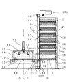
この板材保管棚は、複数の板材Pを積載した保管パレット10を出入自在な収納棚5及び1枚取りされた板材Pを載せて取り出すための板材載置部15を備えた板材パレット11を出入自在な収納棚6を、上下方向に棚フレーム1に備えている。そして、棚フレーム1の一側の柱2に沿って、昇降台55を上下動自在に備え、各収納棚に対して各パレットを出し入れする第1移送機構60と、保持部85を上下動可能な上下動部80とを、昇降台55に備えている。   This plate material storage shelf is provided with a plate material pallet 11 provided with a storage shelf 5 on which a plurality of plate materials P are loaded and a platen placement unit 15 for loading and removing a single plate material P. A flexible storage shelf 6 is provided in the shelf frame 1 in the vertical direction. Along with the pillar 2 on one side of the shelf frame 1, a lifting platform 55 is provided so as to be movable up and down, and a first transfer mechanism 60 for taking in and out each pallet with respect to each storage shelf and a holding portion 85 can be moved up and down. A vertical movement unit 80 is provided on the lifting platform 55.

棚フレーム1は、前面に保管パレット10又は板材パレット11を出し入れするための開口を有する。そして、棚フレーム1の内側には、複数の保管パレット10を収納するために、上下方向に複数段の収納棚5が左右対称に設けられている。その収納棚5に保管パレット10を収納する。また、棚フレーム1の最下段には、板材パレット11を収納する収納棚6が左右対称に設けられている。その収納棚6に板材パレット11を収納する。棚フレーム1の前端に設けた左右の柱2には、昇降台55を案内するガイドレール3が取り付けられている。   The shelf frame 1 has an opening for taking in and out the storage pallet 10 or the plate material pallet 11 on the front surface. Inside the shelf frame 1, a plurality of storage shelves 5 are provided symmetrically in the vertical direction in order to store a plurality of storage pallets 10. The storage pallet 10 is stored in the storage shelf 5. In addition, storage shelves 6 for storing the plate material pallets 11 are provided symmetrically at the lowest level of the shelf frame 1. The plate material pallet 11 is stored in the storage shelf 6. Guide rails 3 for guiding the lifting platform 55 are attached to the left and right columns 2 provided at the front end of the shelf frame 1.

保管パレット10の上面には複数の板材Pが積層状に積載される。保管パレット10は前部左右のプレートに凹部12、後部左右のプレートに凹部13及び側面に複数の車輪14を備え、第1移送機構60により収納棚5を車輪14が転動して移送される。   A plurality of plate materials P are stacked on the upper surface of the storage pallet 10. The storage pallet 10 includes a recess 12 on the front left and right plates, a recess 13 on the left and right rear plates, and a plurality of wheels 14 on the side surfaces. The storage rack 5 is transferred by the wheels 14 rolling by the first transfer mechanism 60. .

板材パレット11の上面には板材載置部15が設けてある。板材載置部15の上には1枚取りされた板材Pが載せられる。板材パレット11は前部左右のプレートに凹部12、後部左右のプレートに凹部13及び側面に複数の車輪14を備え、第1移送機構60により収納棚6を車輪14が転動して移送される。   A plate material placing portion 15 is provided on the upper surface of the plate material pallet 11. A single plate material P is placed on the plate material placement portion 15. The plate material pallet 11 includes a recess 12 on the front left and right plates, a recess 13 on the rear left and right plates, and a plurality of wheels 14 on the side surface. .

昇降台55は、棚フレーム1の前端に設けた左右の柱2に設けたガイドレール3に、沿って転がる複数のガイドローラ56を備えている。昇降台55の内側には、保管パレット10又は板材パレット11を第1移送機構60により移送するときに車輪14が転動する走行面57が左右対称に設けてある。   The lifting platform 55 includes a plurality of guide rollers 56 that roll along the guide rails 3 provided on the left and right columns 2 provided at the front end of the shelf frame 1. A traveling surface 57 on which the wheels 14 roll when the storage pallet 10 or the plate material pallet 11 is transferred by the first transfer mechanism 60 is provided in the left and right sides of the elevator 55.

昇降機構101は主に2本の駆動軸103、各スプロケット、チェーン104及びモータ付減速機102で構成されている。棚フレーム1の上面には2本の駆動軸103が回転自在に配設されている。その2本の駆動軸103の左右両端にはそれぞれ駆動スプロケット105と駆動スプロケット106とが固定されている。駆動軸103の内側(棚フレームの中心側)の駆動スプロケット105、モータ付減速機102の両側の出力軸に固定された駆動スプロケット108とには無端チェーン109が掛け渡されている。そして、駆動軸103の外側(棚フレームの側面側)の駆動スプロケット106の下方にはそれぞれ回転自在に従動スプロケット107が棚フレーム1の柱2に設けられている。チェーン104は駆動軸の外側の駆動スプロケット106と従動スプロケット107とに掛け渡され、チェーン104の両端は昇降台55に接続されている。モータ付減速機102が正逆回転駆動すると昇降台55は柱2に設けたガイドレール3に沿って移動(昇降)することができる。昇降機構101については従来周知であるから、詳細な構成及び動作の説明は省略する。 The elevating mechanism 101 mainly includes two drive shafts 103, each sprocket, a chain 104, and a motor-equipped reducer 102. Two drive shafts 103 are rotatably disposed on the top surface of the shelf frame 1. A drive sprocket 105 and a drive sprocket 106 are fixed to the left and right ends of the two drive shafts 103, respectively. A drive sprocket 105 of the inner drive shaft 103 (the center side of the shelf frame), the endless chain 109 is stretched to a drive sprocket 108 fixed to both sides of the output shaft of the motor with the reduction gear 102. A driven sprocket 107 is provided on the column 2 of the shelf frame 1 so as to be freely rotatable below the drive sprocket 106 outside the drive shaft 103 (on the side of the shelf frame). The chain 104 is stretched over a drive sprocket 106 and a driven sprocket 107 outside the drive shaft, and both ends of the chain 104 are connected to a lifting platform 55. When the motor-equipped speed reducer 102 is driven to rotate in the forward and reverse directions, the lifting platform 55 can move (elevate) along the guide rail 3 provided on the column 2. Since the raising / lowering mechanism 101 is conventionally known, a detailed description of the configuration and operation is omitted.

第1移送機構60は移送方向と平行に昇降台55の内側に、いわゆる、チェーンコンベアを左右対称に配置してある。第1移送機構60は、左右対称に、駆動スプロケット69、複数の従動スプロケット70、テンションスプロケット71及び無端チェーン66を有している。そして、駆動スプロケット69と複数の従動スプロケット70とテンションスプロケット71との間には無端チェーン66が掛け渡されている。無端チェーン66には、突起プレート67及び突起プレート68が設けられている。そして左右の駆動スプロケット69は駆動軸72に固定され、駆動軸72は昇降台55の両側の側板に回転可能に固定されている(図4参照)。駆動軸72にはスプロケット73が固定されている。従動スプロケット70は、昇降台55の側板に回転可能に固定されている。サーボモータ76が駆動軸72の近傍で、かつ昇降台55に配設されている。サーボモータ76の出力軸に固定されたスプロケット74と、スプロケット73との間には、無端チェーン75が掛け渡されている。   In the first transfer mechanism 60, so-called chain conveyors are arranged symmetrically inside the lifting platform 55 in parallel with the transfer direction. The first transfer mechanism 60 has a drive sprocket 69, a plurality of driven sprockets 70, a tension sprocket 71, and an endless chain 66 in a bilaterally symmetrical manner. An endless chain 66 is spanned between the drive sprocket 69, the plurality of driven sprockets 70, and the tension sprocket 71. The endless chain 66 is provided with a protruding plate 67 and a protruding plate 68. The left and right drive sprockets 69 are fixed to the drive shaft 72, and the drive shaft 72 is rotatably fixed to the side plates on both sides of the lifting platform 55 (see FIG. 4). A sprocket 73 is fixed to the drive shaft 72. The driven sprocket 70 is rotatably fixed to the side plate of the lifting platform 55. A servo motor 76 is disposed in the vicinity of the drive shaft 72 and on the lifting platform 55. An endless chain 75 is stretched between the sprocket 74 fixed to the output shaft of the servo motor 76 and the sprocket 73.

昇降台55が、棚フレーム1の各パレットが収納されている各収納棚と、昇降台55に設けた走行面57とを、各パレットが乗り移り可能になるように停止したとき、第1移送機構60は、各収納棚と走行面57とを各パレットの車輪14が転動して、各パレットを出し入れ(移送)することができる。   When the elevator 55 stops the storage shelves in which the pallets of the shelf frame 1 are stored and the running surface 57 provided on the elevator 55 so that the pallets can be transferred, the first transfer mechanism 60, each pallet wheel 14 rolls between each storage shelf and the running surface 57, and each pallet can be taken in and out (transferred).

第1移送機構60のチェーンコンベアの無端チェーン66と、各パレットの各凹部が設けられているプレートとの間には隙間が設けられている。無端チェーン66の側面に設けられている突起プレート67及び突起プレート68は、無端チェーン66が駆動すると各パレットのプレートの凹部に、はまりこむ位置関係になっている。   A gap is provided between the endless chain 66 of the chain conveyor of the first transfer mechanism 60 and the plate on which each recess of each pallet is provided. The projecting plate 67 and the projecting plate 68 provided on the side surface of the endless chain 66 are in a positional relationship such that when the endless chain 66 is driven, the projecting plate 67 and the projecting plate 68 are fitted into the concave portions of the plates of each pallet.

次に第1移送機構60により保管パレット10を昇降台55に移送する手順を説明する。まず、昇降台55が保管パレット10が収納された収納棚5まで移動する。そして、サーボモータ76を回転駆動すると無端チェーン66が駆動し、棚フレーム1の収納棚5に収納された、保管パレット10の前部左右のプレートに設けた凹部12に、突起プレート67がはまる。次に、保管パレット10が引き出され、保管パレット10の後部左右のプレート設けた凹部13に突起プレート68がはまる。更に、保管パレット10が引き出され、昇降台55に移送される。このようにサーボモータ76を回転駆動して保管パレット10を移送する。また、サーボモータ76を逆回転駆動すると、保管パレット10は逆方向に移送され元の収納棚5に戻ることができる。   Next, a procedure for transferring the storage pallet 10 to the lifting platform 55 by the first transfer mechanism 60 will be described. First, the lifting platform 55 moves to the storage shelf 5 in which the storage pallet 10 is stored. When the servo motor 76 is driven to rotate, the endless chain 66 is driven, and the protruding plate 67 fits into the recesses 12 provided in the front left and right plates of the storage pallet 10 stored in the storage shelf 5 of the shelf frame 1. Next, the storage pallet 10 is pulled out, and the protruding plate 68 fits into the recesses 13 provided on the left and right rear portions of the storage pallet 10. Further, the storage pallet 10 is pulled out and transferred to the lifting platform 55. Thus, the servo motor 76 is rotationally driven to transport the storage pallet 10. Further, when the servo motor 76 is driven in reverse rotation, the storage pallet 10 can be transferred in the reverse direction and returned to the original storage shelf 5.

第1移送機構60により保管パレット10を出し入れする方法について説明したが、板材パレット11を出し入れする場合も同様に移送することができる。   Although the method for putting the storage pallet 10 in and out by the first transfer mechanism 60 has been described, the plate material pallet 11 can also be transferred in the same manner.

昇降台55が移動するときは、突起プレート67及び突起プレート68は待避した位置にあり、第1移送機構60の無端チェーン66、突起プレート67及び突起プレート68は、保管パレット10、板材パレット11及び凹部12を備えたプレートに互いに干渉しない位置関係になっている。   When the elevator 55 moves, the protruding plate 67 and the protruding plate 68 are in the retracted position, and the endless chain 66, the protruding plate 67 and the protruding plate 68 of the first transfer mechanism 60 are connected to the storage pallet 10, the plate material pallet 11, and The positional relationship is such that the plates having the recesses 12 do not interfere with each other.

図4に示すように、上下動部80は、上下シリンダ81、連結治具82、上下動部架台83及び一対のガイド84で構成されている。そして、昇降台55を支柱で囲むように構成された上下動部架台83は、昇降台55の両側の側面に取り付けられている。上下動部架台83の上面には上下シリンダ81がロッドを下向きに取付けられ、その両側に一対のガイド84が取り付けられている。   As shown in FIG. 4, the vertical movement unit 80 includes a vertical cylinder 81, a connecting jig 82, a vertical movement unit frame 83, and a pair of guides 84. And the vertical movement part frame 83 comprised so that the raising / lowering stand 55 might be enclosed with a support | pillar is attached to the side surface of the both sides of the raising / lowering stand 55. As shown in FIG. A vertical cylinder 81 is mounted with the rod facing downward on the upper surface of the vertical movement unit frame 83, and a pair of guides 84 are mounted on both sides thereof.

保持部85は複数の真空パッド86、保持フレーム87及び一対のガイド棒88で構成されている。そして、上下シリンダ81のロッドの先端に取り付けた連結治具82には、保持フレーム87が取り付けられている。保持フレーム87は、ガイド棒88を垂直に設置して、上下シリンダ81に平行に取り付けたガイド84により、案内されるようになっている。   The holding portion 85 includes a plurality of vacuum pads 86, a holding frame 87, and a pair of guide bars 88. A holding frame 87 is attached to the connecting jig 82 attached to the tip of the rod of the upper and lower cylinders 81. The holding frame 87 is guided by a guide 84 with a guide bar 88 installed vertically and attached in parallel to the upper and lower cylinders 81.

また保持フレーム87の下面には、複数個の真空パッド86が、吸着面を下向きに取り付けられている。真空パッド86の数量は、板材Pのサイズや重量により適宜変更可能である。上下動部80は上下シリンダ81を駆動して、保持部85を上げ下げできるようになっている。   A plurality of vacuum pads 86 are attached to the lower surface of the holding frame 87 with the suction surface facing downward. The number of vacuum pads 86 can be appropriately changed according to the size and weight of the plate material P. The vertical movement unit 80 can drive the vertical cylinder 81 to raise and lower the holding unit 85.

また、上下シリンダ81は空圧により駆動し、図示を省略した空圧配管や弁類を備えている。また真空パッド86は真空により板材Pを保持し、図示を省略した真空配管や弁類を備えている。   The upper and lower cylinders 81 are driven by pneumatic pressure, and are provided with pneumatic piping and valves not shown. The vacuum pad 86 holds the plate material P by a vacuum, and includes vacuum piping and valves not shown.

そして、第1移送機構60によって保持部85の下方に引き込まれた保管パレット10上の板材Pを保持部85で保持し1枚取り可能に構成されている。更に、第1移送機構60によって保持部85の下方に引き込まれた板材パレット11の板材載置部15に対して保持部85によって1枚取りされた板材Pを載置可能に構成されている。   The plate member P on the storage pallet 10 drawn below the holding unit 85 by the first transfer mechanism 60 is held by the holding unit 85 so that one sheet can be taken. Further, the plate material P picked up by the holding portion 85 can be placed on the plate material placing portion 15 of the plate material pallet 11 drawn by the first transfer mechanism 60 below the holding portion 85.

図示を省略したフォークリフト又はクレーンにより板材Pを保管パレット10に積み込む作業及び1枚取りされた板材Pを板材パレット11の板材載置部15から取り出す作業は、昇降台55が棚フレーム1と接している方向以外の、三方向のいずれかの方向から行うことができる。したがって、上下動部架台83は、昇降台55が棚フレーム1と接している方向以外の三方向から、板材Pを保管パレット10に積載したり、板材載置部15に載せられた板材Pを取り出したりするための開口を有している。   The work of loading the plate material P onto the storage pallet 10 by a forklift or a crane (not shown) and the operation of taking out the single plate material P from the plate material placement portion 15 of the plate material pallet 11 are performed by the lifting platform 55 contacting the shelf frame 1. It can be performed from any one of three directions other than the existing direction. Therefore, the vertical movement unit frame 83 loads the plate material P on the storage pallet 10 or the plate material P placed on the plate material placement unit 15 from three directions other than the direction in which the lifting table 55 is in contact with the shelf frame 1. It has an opening for taking it out.

また、板材Pの積込み及び1枚取りされた板材Pの受け渡しに支障がないように、保持部85の真空パッド86は、真空パッド86の吸着面が板材Pに対して十分な隙間を有するような位置に取付けられている。   Further, the vacuum pad 86 of the holding portion 85 has a sufficient clearance between the suction surface of the vacuum pad 86 and the plate material P so as not to hinder the loading of the plate material P and the delivery of the single plate material P. It is installed in the correct position.

上述した実施例は、上下動部80の動力に上下シリンダ81を用いて構成したが、例えば、モータでワイヤを巻き上げたり、巻き戻したりしてワイヤに吊り下げた保持部85を、上下動させてもよい。また保持部85に真空パッド86を用いて板材Pを保持するようにしたが、板材Pが磁性体の場合は、磁石により板材Pを保持するようにしてもよい。   In the embodiment described above, the vertical cylinder 81 is used for the power of the vertical movement unit 80. For example, the holding unit 85 that is hung on the wire by winding or unwinding the wire with a motor is moved up and down. May be. Moreover, although the board | plate material P was hold | maintained using the vacuum pad 86 in the holding | maintenance part 85, when the board | plate material P is a magnetic body, you may make it hold | maintain the board | plate material P with a magnet.

また、材質が非磁性体で板材Pの表面に凹凸及び/又は穴があり、真空パッド86により板材Pを保持できないときは、板材Pの両側の側面を把持して板材Pを保持するようにしてもよい。   Further, when the material is a non-magnetic material and there are irregularities and / or holes on the surface of the plate material P, and the plate material P cannot be held by the vacuum pad 86, the side surfaces on both sides of the plate material P are gripped to hold the plate material P. May be.

本発明の板材保管棚には、保管パレット10及び/又は板材パレット11が停止する位置が、次のように4箇所ある。それは板材Pを保管パレット10に積み込む積込み位置Aと、板材Pを積載している保管パレット10を棚フレーム1の収納棚5に収納したり、板材パレット11を棚フレーム1の収納棚6に収納したりする保管位置Bと、保管パレット10に積載された最上部の板材Pを1枚取りしたり、1枚取りした板材Pを板材パレット11の板材載置部15上に載置したりする1枚取り位置Cと、板材パレット11に載っている1枚取りされた板材Pを取り出す取出し位置Dとである。   The plate material storage shelf of the present invention has four positions where the storage pallet 10 and / or the plate material pallet 11 stop as follows. That is, the loading position A where the plate material P is loaded on the storage pallet 10 and the storage pallet 10 on which the plate material P is loaded are stored in the storage shelf 5 of the shelf frame 1, or the plate material pallet 11 is stored in the storage shelf 6 of the shelf frame 1. The storage position B to be processed and the uppermost plate material P loaded on the storage pallet 10 are taken, or the single plate material P is placed on the plate material placement portion 15 of the plate material pallet 11. The single-sheet pick-up position C and the pick-up position D for picking up the single-sheet plate P placed on the plate material pallet 11.

本実施例の保管パレット10及び/又は板材パレット11が停止する各位置は、図3で示すように、積込み位置A、1枚取り位置C及び取出し位置Dの三位置が同位置で、昇降台55の上下動部80が取り付いている箇所に設けてある。また、保管位置Bを棚フレーム1に設けてある。   As shown in FIG. 3, the storage pallet 10 and / or the plate material pallet 11 of this embodiment are stopped at the same three positions, ie, the loading position A, the single picking position C, and the picking position D. It is provided at a location where 55 vertical movement portions 80 are attached. A storage position B is provided on the shelf frame 1.

板材Pを保管パレット10に積み込み、収納(保管)する手順を図3を参照して説明する。保管パレット10に積載された板材Pが空になると、昇降台55は空の保管パレット10が収納された収納棚5まで移動する。そして第1移送機構60により、棚フレーム1の保管位置Bから昇降台55の1枚取り位置Cに空の保管パレット10を移送し、昇降台55は板材Pを積み込む高さまで移動する。本実施例の板材保管棚の場合は、積込み位置Aと1枚取り位置Cとが同じ位置なので、この位置で板材Pが、図示を省略したフォークリフトにより保管パレット10の上に積載される。そして、昇降台55は空の保管パレット10が収納されていた収納棚5まで移動し、第1移送機構60により保管パレット10を棚フレーム1の保管位置Bに移送し収納する。   A procedure for loading and storing (storing) the plate material P on the storage pallet 10 will be described with reference to FIG. When the plate material P loaded on the storage pallet 10 becomes empty, the lift 55 moves to the storage shelf 5 in which the empty storage pallet 10 is stored. Then, the empty storage pallet 10 is transferred from the storage position B of the shelf frame 1 to the single picking position C of the lifting platform 55 by the first transfer mechanism 60, and the lifting platform 55 moves to a height at which the plate material P is loaded. In the case of the plate material storage shelf of the present embodiment, the loading position A and the single picking position C are the same position, so the plate material P is loaded on the storage pallet 10 at this position by a forklift (not shown). The elevator 55 moves to the storage shelf 5 in which the empty storage pallet 10 was stored, and the storage pallet 10 is transferred to the storage position B of the shelf frame 1 by the first transfer mechanism 60 and stored.

次に、板材Pを1枚取りする手順を図5を参照して説明する。同図(A)のように、昇降台55は、板材加工機で加工する板材Pを積載した保管パレット10が収納してある収納棚5まで移動する。そして、第1移送機構60により保管パレット10を棚フレーム1の保管位置Bから昇降台55の1枚取り位置Cに移送する。   Next, a procedure for taking one plate P will be described with reference to FIG. As shown in FIG. 5A, the lifting / lowering base 55 moves to the storage shelf 5 in which the storage pallet 10 loaded with the plate materials P processed by the plate material processing machine is stored. Then, the storage pallet 10 is transferred from the storage position B of the shelf frame 1 to the single picking position C of the lifting platform 55 by the first transfer mechanism 60.

次に同図(B)のように、保持部85は、上下動部80により保管パレット10に積層状に積載された最上部の板材Pに、真空パッド86が密着するまで下がる。そして、保持部85は、真空により板材Pを保持する。その後、保持部85は上下動部80により板材Pを保持した状態で上がり、最上部の板材Pは1枚取りされる。   Next, as shown in FIG. 6B, the holding portion 85 is lowered by the vertical movement portion 80 until the vacuum pad 86 comes into close contact with the uppermost plate material P stacked on the storage pallet 10. And the holding | maintenance part 85 hold | maintains the board | plate material P with a vacuum. Thereafter, the holding portion 85 is raised in a state where the plate material P is held by the vertical movement portion 80, and one piece of the uppermost plate material P is taken.

次に同図(C)のように、第1移送機構60により保管パレット10を、昇降台55の1枚取り位置Cから保管パレット10が収納されていた棚フレーム1の保管位置Bに移送し収納する。   Next, as shown in FIG. 5C, the storage pallet 10 is transferred by the first transfer mechanism 60 from the single picking position C of the lifting platform 55 to the storage position B of the shelf frame 1 in which the storage pallet 10 was stored. Store.

1枚取りされた板材Pを取り出す手順を説明する。図5で説明したように1枚取り位置Cで保持部85は、板材Pを保持して持ち上げ1枚取りする。保管パレット10を棚フレーム1の収納棚5に移送し収納した後に、1枚取りされた板材Pを保持部85が保持した状態で、昇降台55は板材パレット11が収納された収納棚6まで移動する。その後、第1移送機構60により板材パレット11を保管位置Bから1枚取り位置Cに移送する。そして、1枚取りされた板材Pを保持した保持部85は、上下動部80により下がる。次に、真空パッド86の真空を解除し、1枚取りされた板材Pは、板材パレット11の板材載置部15の上に受け渡される。そして、保持部85は、上下動部80により上がる。昇降台55は板材Pが取り出される位置まで移動(昇降)する。本実施例の板材保管棚の場合は、1枚取り位置Cと取出し位置Dとが同じ位置なのでこの位置で、板材パレット11の板材載置部15の上に載っている1枚取りされた板材Pは取り出される。   A procedure for taking out the single plate material P will be described. As described with reference to FIG. 5, the holding portion 85 holds the plate material P and picks up one piece at the single picking position C. After the storage pallet 10 is transferred to and stored in the storage shelf 5 of the shelf frame 1, the lift 55 extends to the storage shelf 6 in which the plate pallet 11 is stored in a state where the picked plate material P is held by the holding unit 85. Moving. Thereafter, the plate material pallet 11 is transferred from the storage position B to the single picking position C by the first transfer mechanism 60. And the holding | maintenance part 85 holding the board | plate material P picked up by one sheet falls by the up-and-down moving part 80. FIG. Next, the vacuum of the vacuum pad 86 is released, and the single plate material P is transferred onto the plate material placement portion 15 of the plate material pallet 11. The holding unit 85 is raised by the vertical movement unit 80. The lift 55 moves (lifts) to a position where the plate material P is taken out. In the case of the plate material storage shelf of the present embodiment, since the one-sheet pick-up position C and the pick-up position D are the same position, the single-sheet plate material that is placed on the plate material placing portion 15 of the plate material pallet 11 at this position. P is taken out.

次に、板材パレット11の板材載置部15について図6〜図10を参照して説明する。これから説明するいずれか一つの板材載置部15を板材パレット11の上面に取り付けることができる。   Next, the plate material mounting portion 15 of the plate material pallet 11 will be described with reference to FIGS. Any one plate material mounting portion 15 to be described below can be attached to the upper surface of the plate material pallet 11.

板材載置部15は、板材パレット11の移送方向に対して平行な方向に、かつ隙間を設けて互いに並行に設けられた複数の平板状の板材載置部材16により構成することができる。板材載置部材16は板材Pを板材載置部材16上に載置したさい、板材Pの下方に図示を省略したフォークリフトのフォーク又は専用のフォークを挿入可能な空隙を形成する厚みを有する。そして、板材パレット11の移送方向に対して平行な方向から図示を省略したフォークリフトのフォーク又は専用のフォークを挿入し板材Pを取り出すことができる。また、板材Pは1枚取りされて板材載置部材16上に載置されているので、人手で運べる重さの板材Pは人手で取り出し運ぶこともできる。また、板材載置部材16の取り付ける向きを板材パレット11の移送方向に対して直交する方向に変え、板材パレット11の移送方向に対して直交する方向から図示を省略したフォークリフトのフォーク又は専用のフォークを挿入し板材Pを取り出すようにしてもよい。   The plate material placing portion 15 can be configured by a plurality of plate-like plate material placing members 16 provided in parallel to each other with a gap in a direction parallel to the transport direction of the plate material pallet 11. When the plate material P is placed on the plate material placement member 16, the plate material placement member 16 has a thickness that forms a gap into which a fork of a forklift (not shown) or a dedicated fork can be inserted below the plate material P. Then, a fork lift fork or a special fork (not shown) can be inserted from a direction parallel to the transport direction of the plate material pallet 11 to take out the plate material P. Further, since one plate P is taken and placed on the plate placing member 16, the plate P having a weight that can be carried manually can be taken out and carried manually. In addition, the fork of the forklift or the dedicated fork whose illustration is omitted from the direction orthogonal to the transfer direction of the plate material pallet 11 by changing the mounting direction of the plate material mounting member 16 to the direction orthogonal to the transfer direction of the plate material pallet 11. May be inserted and the plate material P may be taken out.

また、板材載置部15は、図6に示すように、平板状の板材載置部材16を板材パレット11の移送方向に対して平行な方向に、かつ1列に隙間を設けて複数個配設し、それを互いに隙間を設けて並行に複数列配設した構成としてもよい。板材載置部材16は、板材Pを板材載置部材16上に載置したさい、板材Pの下方に図示を省略したフォークリフトのフォーク又は専用のフォークを挿入可能な空隙を形成する厚みを有する。また、板材載置部材16は、板材パレット11の移送方向に対して平行な方向又は直交する方向から、図示を省略したフォークリフトのフォーク又は専用のフォークを隙間に挿入し、板材Pを持ち上げ取り出すことができるように配設されている。そして、板材Pは1枚取りされて板材載置部材16上に載置されているので、人手で運べる重さの板材Pは人手で取り出し運ぶこともできる。   In addition, as shown in FIG. 6, the plate material placement unit 15 includes a plurality of flat plate material placement members 16 arranged in a direction parallel to the transport direction of the plate material pallet 11 and with a gap in one row. It is good also as a structure which provided and arranged several rows in parallel, providing a clearance gap mutually. When the plate material P is placed on the plate material placement member 16, the plate material placement member 16 has a thickness that forms a gap into which a fork of a forklift or a special fork (not shown) can be inserted below the plate material P. In addition, the plate material mounting member 16 inserts a fork of a forklift (not shown) or a dedicated fork into the gap from a direction parallel to or orthogonal to the transfer direction of the plate material pallet 11 and lifts and removes the plate material P. It is arranged to be able to. Since one plate P is taken and placed on the plate placing member 16, the plate P having a weight that can be carried manually can be taken out and carried manually.

図7に示すように、板材載置部15は、互いに平行に離間対向した1対のフレーム18の間に回転自在なフリーローラ17を複数備えた構成にすることができる。フリーローラ17は、板材パレット11の移送方向に対して直交する方向に、板材パレットの上面の1対のフレーム18により取付けられている。フリーローラ17は、C形鋼により構成された1対のフレーム18に対して直角で、かつ互いのフリーローラ17が平行になるように適宜間隔で支軸19により回転可能に取り付けられている。そして、板材パレット11の移送方向に対して平行な方向から板材Pを取り出すことができる。また、板材Pは1枚取りされてフリーローラ17上に載置されているので、人手で運べる重さの板材Pは人手で取り出し運ぶこともできる。   As shown in FIG. 7, the plate material mounting portion 15 can be configured to include a plurality of free rollers 17 that are rotatable between a pair of frames 18 that are spaced apart from each other in parallel. The free roller 17 is attached by a pair of frames 18 on the upper surface of the plate material pallet in a direction orthogonal to the transfer direction of the plate material pallet 11. The free rollers 17 are attached to a pair of frames 18 made of C-shaped steel at a right angle and rotatably supported by support shafts 19 at appropriate intervals so that the free rollers 17 are parallel to each other. And the board | plate material P can be taken out from the direction parallel to the transfer direction of the board | plate material pallet 11. FIG. Further, since one plate material P is picked up and placed on the free roller 17, the plate material P having a weight that can be carried manually can be taken out and carried manually.

また、フリーローラ17の取り付ける向きを板材パレット11の移送方向に対して平行な方向に変え、板材パレット11の移送方向に対して直交する方向から板材Pを取り出すようにしてもよい。また、上述した実施例はフリーローラ17を1列で構成したが、長さの短いローラを複数列設置した構成にしてもよい。   Alternatively, the mounting direction of the free roller 17 may be changed to a direction parallel to the transfer direction of the plate material pallet 11, and the plate material P may be taken out from a direction orthogonal to the transfer direction of the plate material pallet 11. In the above-described embodiment, the free rollers 17 are configured in one row, but a configuration in which a plurality of rollers having a short length are installed may be employed.

板材載置部15は、図8に示すように、回転自在なフリーボールベアリング20(ボールトランスファとも呼ばれる)を複数備えた構成とすることができる。そして、フリーボールベアリング20はボールを上向きに適宜間隔で格子状に配置されている。フリーボールベアリング20の数量は、板材Pのサイズや重量により適宜変更可能である。   As shown in FIG. 8, the plate material mounting portion 15 can be configured to include a plurality of free ball bearings 20 (also referred to as ball transfer) that are rotatable. The free ball bearings 20 are arranged in a grid pattern with balls at appropriate intervals upward. The quantity of the free ball bearings 20 can be appropriately changed depending on the size and weight of the plate material P.

板材パレット11の移送方向に対して平行な方向又は直交する方向から板材Pを取り出すことができる。そして、板材Pは1枚取りされてフリーボールベアリング20上に載置されているので、人手で運べる重さの板材Pは人手で取り出し運ぶこともできる。   The plate material P can be taken out from a direction parallel to or perpendicular to the transport direction of the plate material pallet 11. Since one plate P is taken and placed on the free ball bearing 20, the plate P having a weight that can be carried manually can be taken out and carried manually.

板材載置部15は、図9に示すように、1枚取りされた板材Pを搬送する搬送機構21を備えることができる。搬送機構21は、主に、駆動源のモータ内蔵ローラ23、複数の従動ローラ24及び1対のコンベアフレーム25により構成されている。駆動源のモータ内蔵ローラ23及び複数の従動ローラ24は、板材パレット11の移送方向に対して直交する方向になるように、板材パレット11の上面に設けた1対のコンベアフレーム25により取付けられている。モータ内蔵ローラ23及び従動ローラ24は、端部に2連のスプロケット26が固定され、C形鋼により構成され互いに平行に離間対向した1対のコンベアフレーム25に対して直角で、かつ互いの各ローラが平行になるように適宜間隔で支軸27により回転可能に取り付けられている。そして、互いに隣り合うローラどうしの2連のスプロケット26には無端チェーン28が掛け渡されている。1,2本目のローラに固定されている2連のスプロケット26には右側のスプロケットに無端チェーン28を掛け渡し、次の2,3本目のローラに固定されている2連のスプロケット26には左側のスプロケットに無端チェーン28を掛け渡し、更に、次の3,4本のローラに固定されている2連のスプロケット26には右側のスプロケットというように、互い違いに無端チェーン28を掛け渡してある。   As shown in FIG. 9, the plate material placement unit 15 can include a transport mechanism 21 that transports a single plate material P taken. The transport mechanism 21 is mainly composed of a motor built-in roller 23 as a driving source, a plurality of driven rollers 24, and a pair of conveyor frames 25. The drive source motor built-in roller 23 and the plurality of driven rollers 24 are attached by a pair of conveyor frames 25 provided on the upper surface of the plate material pallet 11 so as to be in a direction orthogonal to the transfer direction of the plate material pallet 11. Yes. The motor built-in roller 23 and the driven roller 24 have two sprockets 26 fixed to their ends, and are perpendicular to a pair of conveyor frames 25 that are made of C-shaped steel and are opposed to each other in parallel. The rollers are rotatably attached to the support shaft 27 at appropriate intervals so that the rollers are parallel to each other. An endless chain 28 is stretched around two sprockets 26 adjacent to each other. An endless chain 28 is stretched over the right sprocket to the two sprockets 26 fixed to the first and second rollers, and the left side is connected to the second sprocket 26 fixed to the second and third rollers. An endless chain 28 is stretched over the two sprockets 26, and the endless chain 28 is alternately looped over the two sprockets 26 fixed to the next three or four rollers, such as the right sprocket.

1枚取りされた板材Pをモータ内蔵ローラ23及び複数の従動ローラ24の上に載せ、モータ内蔵ローラ23を駆動し、板材パレット11の移送方向に対して平行な方向に、1枚取りされた板材Pを搬送することができる。昇降台55に隣接するように板材Pを受け渡す搬送装置を設ければ、1枚取りされた板材Pを自動で次工程へ搬送することができる。また、板材Pは1枚取りされて各ローラ上に載置されているので、人手で運べる重さの板材Pは人手で取り出し運ぶこともできる。   The single plate material P was placed on the motor built-in roller 23 and the plurality of driven rollers 24, the motor built-in roller 23 was driven, and one plate was picked in a direction parallel to the transfer direction of the plate material pallet 11. The plate material P can be conveyed. If a conveying device that delivers the plate material P so as to be adjacent to the elevator 55 is provided, the single plate material P can be automatically conveyed to the next process. Further, since one sheet P is picked up and placed on each roller, the sheet P having a weight that can be carried manually can be taken out and carried manually.

また、モータ内蔵ローラ23をクラッチ付に換え、クラッチを切ることでローラを外部から回せる状態にし、ローラ上に載せられた板材Pを引き出せるようにしてもよい。   In addition, the motor built-in roller 23 may be replaced with a clutch, and the clutch may be disengaged so that the roller can be rotated from the outside so that the plate material P placed on the roller can be pulled out.

また、モータ内蔵ローラ23及び複数の従動ローラ24の取り付ける向きを、板材パレット11の移送方向に対して平行な方向に変え、板材パレット11の移送方向に対して直交する方向に板材Pを搬送するようにしてもよい。   Further, the mounting direction of the motor built-in roller 23 and the plurality of driven rollers 24 is changed to a direction parallel to the transfer direction of the plate material pallet 11, and the plate material P is conveyed in a direction orthogonal to the transfer direction of the plate material pallet 11. You may do it.

上述した搬送機構21はローラコンベアで板材Pを搬送したが、例えば、無端ベルトコンベア、チェーンコンベアなどとしてもよい。 Although transport mechanism 21 described above was conveyed to sheet P by a roller conveyor, for example, an endless belt conveyor, but it may also as such a chain conveyor.

また、搬送機構21は、モータ内蔵ローラ23、複数の従動ローラ24及び1対のコンベアフレーム25で構成したが、複数のモータ内蔵ローラ23及び1対のコンベアフレームにより構成してもよい。そして、モータ内蔵ローラ23は、互いに平行に離間対向した1対のコンベアフレームに対し直角で、かつ互いのローラが平行になるように適宜間隔で支軸により回転可能に取り付けてもよい。   In addition, the transport mechanism 21 is configured by the motor built-in roller 23, the plurality of driven rollers 24, and the pair of conveyor frames 25, but may be configured by the plurality of motor built-in rollers 23 and the pair of conveyor frames. The motor built-in roller 23 may be mounted so as to be rotatable by a support shaft at an appropriate interval so as to be perpendicular to a pair of conveyor frames that are spaced apart from each other in parallel and are parallel to each other.

板材載置部15は、図10に示すように、1枚取りされた板材Pを搬送する搬送機構22を備えることができる。搬送機構22の駆動力は、板材載置部15を有する板材パレット11以外に備えた駆動源のモータ43から駆動力伝達手段40により、搬送機構22に伝達することができる。   As shown in FIG. 10, the plate material placement unit 15 can include a conveyance mechanism 22 that conveys a single plate material P taken. The driving force of the conveying mechanism 22 can be transmitted to the conveying mechanism 22 by the driving force transmitting means 40 from a motor 43 of a driving source provided in addition to the plate material pallet 11 having the plate material placing portion 15.

搬送機構22は、主に、複数の従動ローラ30、1対のコンベアフレーム32及び駆動力伝達手段40により構成されている。複数の従動ローラ30は、板材パレット11の移送方向に対して直交する方向になるように、板材パレット11の上面に設けた1対のコンベアフレーム32により取付けられている。従動ローラ30の端部には2連のスプロケット35が固定され、従動ローラ30は、互いに平行に離間対向した1対のC形鋼により構成されたコンベアフレーム32に対して直角で、かつ互いの従動ローラ30が平行になるように適宜間隔で支軸31により回転可能に取り付けられている。   The transport mechanism 22 is mainly composed of a plurality of driven rollers 30, a pair of conveyor frames 32, and driving force transmission means 40. The plurality of driven rollers 30 are attached by a pair of conveyor frames 32 provided on the upper surface of the plate material pallet 11 so as to be in a direction orthogonal to the transfer direction of the plate material pallet 11. A pair of sprockets 35 are fixed to the end of the driven roller 30, and the driven roller 30 is perpendicular to the conveyor frame 32 made of a pair of C-shaped steels that are spaced apart from each other in parallel with each other. The driven roller 30 is rotatably attached to the support shaft 31 at appropriate intervals so as to be parallel.

そして、板材パレット11に搬送機構22が取り付いている面と反対面の下面に駆動軸33が回転可能に固定され、その駆動軸33には歯車34及びスプロケット36が固定されている。互いに隣り合う従動ローラ30の2連のスプロケット35の間には、無端チェーン37が互い違いに掛け渡されている。その内の1箇所は互いに隣り合う従動ローラ30の2連のスプロケット35と、駆動軸33に固定されたスプロケット36との間に無端チェーン38が掛け渡されている。   A drive shaft 33 is rotatably fixed to the lower surface opposite to the surface on which the transport mechanism 22 is attached to the plate material pallet 11, and a gear 34 and a sprocket 36 are fixed to the drive shaft 33. Between the two sprockets 35 of the driven rollers 30 adjacent to each other, endless chains 37 are alternately wound around. In one of them, an endless chain 38 is stretched between two sprockets 35 of driven rollers 30 adjacent to each other and a sprocket 36 fixed to the drive shaft 33.

1枚取りされた板材Pを取り出す位置に板材パレット11が移送されたとき、板材パレット11の下面に設けた歯車34に、昇降台55に取り付けた駆動力伝達手段40が揺動し駆動源のモータ43から搬送機構22に駆動力が伝達される。   When the plate material pallet 11 is transferred to the position where the single plate material P is taken out, the driving force transmission means 40 attached to the lifting platform 55 swings on the gear 34 provided on the lower surface of the plate material pallet 11 and the drive source A driving force is transmitted from the motor 43 to the transport mechanism 22.

駆動力伝達手段40は、主に、揺動可能に取り付けられた揺動プレート41、シリンダ42、駆動源のモータ43、歯車44、出力軸45、スプロケット46及びスプロケット47により構成されている。揺動プレート41にはモータ43が取り付けられ、モータ43の出力軸にはスプロケット46が固定されている。また、揺動プレート41には出力軸45が回転可能に固定され、出力軸45にはスプロケット47と歯車44とが固定されている。スプロケット46とスプロケット47との間には無端チェーン48が掛け渡されている。そして、シリンダ42のロッド側には揺動プレート41が取付けられている。シリンダ42は昇降台55に取付けられている。シリンダ42を駆動すると揺動プレート41が揺動し、板材パレット11側の歯車34と駆動力伝達手段40側の歯車44がかみ合い駆動力を伝達できる。   The driving force transmission means 40 mainly includes a swing plate 41, a cylinder 42, a drive source motor 43, a gear 44, an output shaft 45, a sprocket 46, and a sprocket 47, which are mounted so as to be swingable. A motor 43 is attached to the swing plate 41, and a sprocket 46 is fixed to the output shaft of the motor 43. An output shaft 45 is rotatably fixed to the swing plate 41, and a sprocket 47 and a gear 44 are fixed to the output shaft 45. An endless chain 48 is stretched between the sprocket 46 and the sprocket 47. A swing plate 41 is attached to the rod side of the cylinder 42. The cylinder 42 is attached to the lifting platform 55. When the cylinder 42 is driven, the swinging plate 41 swings, and the gear 34 on the plate material pallet 11 side and the gear 44 on the driving force transmitting means 40 side mesh with each other so that the driving force can be transmitted.

また、シリンダ42は空圧により駆動し、図示を省略した空圧配管や弁類を備えている。   The cylinder 42 is driven by pneumatic pressure, and includes pneumatic piping and valves not shown.

1枚取りされた板材Pを板材パレット11の搬送機構22の上に載せ、歯車34と歯車44とがかみ合った状態でモータ43を駆動すると駆動力伝達手段40を介して、回転駆動力が搬送機構22に伝達されて、板材パレット11の移送方向に対して平行な方向に、1枚取りされた板材Pを自動で搬送することができる。また、駆動力伝達手段40を昇降台55に取付け、板材パレット11を昇降台55に移送した後、駆動力伝達手段40をシリンダ42で作動させ、駆動源から駆動力を伝達し、搬送機構22を駆動し板材を搬送することができる。そして、昇降台55に隣接するように板材Pを受け渡す搬送装置を設ければ1枚取りされた板材Pを自動で次工程へ搬送することができる。   When the picked sheet material P is placed on the conveying mechanism 22 of the sheet material pallet 11 and the motor 43 is driven with the gear 34 and the gear 44 engaged, the rotational driving force is conveyed via the driving force transmitting means 40. The plate material P, which is transmitted to the mechanism 22 and taken in a direction parallel to the transfer direction of the plate material pallet 11, can be automatically conveyed. Further, after the driving force transmitting means 40 is attached to the lifting platform 55 and the plate material pallet 11 is transferred to the lifting platform 55, the driving force transmitting means 40 is operated by the cylinder 42 to transmit the driving force from the driving source, and the transport mechanism 22 To drive the plate material. And if the conveying apparatus which delivers the board | plate material P so that it may adjoin to the raising / lowering stand 55 is provided, the board | plate material P picked up by 1 sheet can be automatically conveyed to the following process.

また、板材Pは1枚取りされて複数の従動ローラ30上に載置されているので、人手で運べる重さの板材Pは人手で取り出し運ぶこともできる。   Further, since one plate material P is picked up and placed on the plurality of driven rollers 30, the plate material P having a weight that can be carried manually can be taken out and carried manually.

また、駆動力伝達手段40を後述する置き台90又は後述する積込み台95に設け、板材パレット11が置き台90又は積込み台95に移送された後、駆動力伝達手段40をシリンダ42で作動させ、駆動源から駆動力を伝達し、搬送機構22を駆動し板材Pを自動で搬送することもできる。   Further, the driving force transmission means 40 is provided on a cradle 90 to be described later or a loading base 95 to be described later. After the plate material pallet 11 is transferred to the cradle 90 or the loading base 95, the driving force transmission means 40 is operated by the cylinder 42. The driving force can be transmitted from the driving source to drive the transport mechanism 22 to automatically transport the plate material P.

また、複数の従動ローラ30の取り付ける向きを、板材パレット11の移送方向に対して平行な方向に変え、板材パレット11の移送方向に対して直交する方向に板材Pを搬送するようにしてもよい。また、モータ43をクラッチ付モータに換え、クラッチを切り、搬送機構22を外部から回せる状態にし、搬送機構22上に載せられた板材Pを引き出せるようにしてもよい。   Further, the direction in which the plurality of driven rollers 30 are attached may be changed to a direction parallel to the transfer direction of the plate material pallet 11, and the plate material P may be conveyed in a direction orthogonal to the transfer direction of the plate material pallet 11. . Alternatively, the motor 43 may be replaced with a motor with a clutch, the clutch may be disengaged, the transport mechanism 22 can be rotated from the outside, and the plate material P placed on the transport mechanism 22 can be pulled out.

上述した実施例の搬送機構22は、ローラコンベアで板材Pを搬送するようにしたが、例えば、無端ベルトコンベア又はチェーンコンベアで板材Pを搬送するようにしてもよい。   Although the transport mechanism 22 of the above-described embodiment transports the plate material P by the roller conveyor, the transport material 22 may be transported by, for example, an endless belt conveyor or a chain conveyor.

本実施例では、板材パレット11を収納する収納棚6を最下段に設けたが、収納棚6の位置は使用状況により適宜な高さとしてもよい。   In the present embodiment, the storage shelf 6 for storing the plate material pallet 11 is provided at the lowermost stage, but the position of the storage shelf 6 may be set to an appropriate height depending on the use situation.

棚フレーム1に板材パレット11を出入自在な収納棚6を複数段備え、各収納棚に異なった板材載置部15を備えた板材パレット11を収納すれば、異なる方法で板材Pの取り出し、又は異なる方向から板材Pの取り出しができる。   If the shelf frame 1 is provided with a plurality of storage shelves 6 through which the plate material pallets 11 can freely enter and exit, and the plate material pallets 11 having different plate material placement portions 15 are stored in the respective storage shelves, the plate material P can be taken out in different ways, or The plate material P can be taken out from different directions.

例えば、板材載置部15が搬送機構22で構成され、昇降台55に設けた駆動力伝達手段40により、搬送機構22に駆動力が伝達される板材パレット11と、板材載置部15が板材載置部材16で構成された板材パレット11とを各収納棚に収納する。板材載置部15が搬送機構22で構成された板材パレット11の板材Pの取り出しはモータを駆動し板材Pを搬送し取り出すことができる。また、板材載置部15が板材載置部材16で構成された板材パレット11の板材Pの取り出しは、板材Pの下方に図示を省略したフォークリフトのフォークを差し込み、取り出すことができる。   For example, the plate material placing portion 15 is constituted by the transport mechanism 22, and the plate material pallet 11 to which the drive force is transmitted to the transport mechanism 22 by the driving force transmitting means 40 provided on the lifting platform 55, and the plate material placing portion 15 is the plate material. The plate material pallet 11 composed of the mounting member 16 is stored in each storage shelf. The plate material P of the plate material pallet 11 in which the plate material placement unit 15 is configured by the conveyance mechanism 22 can be taken out by driving the motor to convey the plate material P. Further, the plate material P of the plate material pallet 11 in which the plate material mounting portion 15 is configured by the plate material mounting member 16 can be taken out by inserting a fork of a forklift (not shown) below the plate material P.

また、板材パレット11の板材載置部15を、搬送機構21が板材パレット11の移送方向に対して平行な方向に板材Pを搬送するように構成し、もう片方の板材パレット11の板材載置部15を、搬送機構21が板材パレット11の移送方向に対して直交する方向に板材Pを搬送するように構成する。このように搬送方向の異なった板材載置部15を有する板材パレット11を各収納棚に設置し、板材Pを載置する板材パレット11を替えるごとに、板材Pの取り出し方向が変わるようにすることもできる。   Further, the plate material placement portion 15 of the plate material pallet 11 is configured such that the transport mechanism 21 conveys the plate material P in a direction parallel to the transfer direction of the plate material pallet 11, and the plate material placement of the other plate material pallet 11 is performed. The part 15 is configured such that the transport mechanism 21 transports the plate material P in a direction orthogonal to the transport direction of the plate material pallet 11. In this way, the plate material pallets 11 having the plate material placement portions 15 having different transport directions are installed in the respective storage shelves, and the take-out direction of the plate material P is changed every time the plate material pallet 11 on which the plate material P is placed is changed. You can also

実施例2の板材保管棚について、図11を参照して説明する。本実施例は、前記実施例1に対して、保持部85を上下動可能な上下動部80を、棚フレーム1内に備えている点で特に異なり、その他の前記実施例1と共通部分には同一符号を付して、その説明を省略する。   The board | plate material storage shelf of Example 2 is demonstrated with reference to FIG. The present embodiment is different from the first embodiment in that a vertical movement portion 80 capable of moving the holding portion 85 in the vertical direction is provided in the shelf frame 1. Are denoted by the same reference numerals, and the description thereof is omitted.

棚フレーム1は、前面に各パレットを出し入れするための開口を有する。そして、棚フレーム1の内側には、複数の保管パレット10を収納するために、上下方向に複数段の収納棚5が左右対称に設けられている。   The shelf frame 1 has an opening for putting each pallet in and out. Inside the shelf frame 1, a plurality of storage shelves 5 are provided symmetrically in the vertical direction in order to store a plurality of storage pallets 10.

収納棚5の下方には、上下動部80を取り付けた上下動部フレーム89が設けてある。上下動部フレーム89は棚フレーム1の柱に固定されている。上下動部フレーム89の下方(保持部85の下方)には、板材パレット11を収納するために収納棚6が左右対称に設けられている。保持部85が上昇端にあるときに、板材パレット11は、収納棚6に収納される。そして、保持部85が下降するときには、板材パレット11は昇降台55側に移送される。   Below the storage shelf 5, a vertical movement part frame 89 to which a vertical movement part 80 is attached is provided. The vertically moving part frame 89 is fixed to the column of the shelf frame 1. Below the vertical moving part frame 89 (below the holding part 85), the storage shelves 6 are provided symmetrically in order to store the plate material pallet 11. When the holding portion 85 is at the rising end, the plate material pallet 11 is stored in the storage shelf 6. And when the holding | maintenance part 85 descend | falls, the board | plate material pallet 11 is transferred to the raising / lowering stand 55 side.

収納棚6の下方には、保管パレット10に積載された板材Pを保持部85で1枚取りするときに、保管パレット10を収納する収納棚8が左右対称に設けられている。   Below the storage shelf 6, a storage shelf 8 for storing the storage pallet 10 is provided symmetrically when one plate P loaded on the storage pallet 10 is picked up by the holding portion 85.

そして、第1移送機構60によって保持部85の下方に引き込まれ収納棚8に収納された保管パレット10上の板材Pを保持部85で保持し、1枚取り可能に構成されている。更に、第1移送機構60によって保持部85の下方に引き込まれ収納棚6に収納された板材パレット11の板材載置部15に対して保持部85によって1枚取りされた板材Pを載置可能に構成されている。   The plate member P on the storage pallet 10 drawn into the lower portion of the holding portion 85 by the first transfer mechanism 60 and stored in the storage shelf 8 is held by the holding portion 85 so that one sheet can be taken. Furthermore, the plate P picked up by the holding portion 85 can be placed on the plate placement portion 15 of the plate pallet 11 which is drawn below the holding portion 85 by the first transfer mechanism 60 and stored in the storage shelf 6. It is configured.

本実施例の保管パレット10及び/又は板材パレット11が停止する各位置は、図11で示すように、積込み位置A及び取出し位置Dを昇降台55に設けてある。また保管位置B及び1枚取り位置Cを棚フレーム1に設けてある。   Each position where the storage pallet 10 and / or the plate material pallet 11 of this embodiment stops is provided with a loading position A and an extraction position D on the lifting platform 55 as shown in FIG. Further, a storage position B and a single picking position C are provided on the shelf frame 1.

板材Pを保管パレット10に積み込み、収納する手順を図11を参照して説明する。保管パレット10に積載された板材Pが空になると、昇降台55は空の保管パレット10が収納された収納棚5まで移動する。そして第1移送機構60により、棚フレーム1の保管位置Bから昇降台55の積込み位置Aに空の保管パレット10を移送し、昇降台55は板材Pを積み込む高さまで移動する。この位置で板材Pが、図示を省略したフォークリフトにより保管パレット10の上に積載される。そして、昇降台55は空の保管パレット10が収納されていた収納棚5まで移動し、第1移送機構60により保管パレット10を棚フレーム1の保管位置Bに移送し収納する。   A procedure for loading and storing the plate material P on the storage pallet 10 will be described with reference to FIG. When the plate material P loaded on the storage pallet 10 becomes empty, the lift 55 moves to the storage shelf 5 in which the empty storage pallet 10 is stored. Then, the empty storage pallet 10 is transferred from the storage position B of the shelf frame 1 to the loading position A of the lifting platform 55 by the first transfer mechanism 60, and the lifting platform 55 moves to a height at which the plate material P is loaded. At this position, the plate material P is loaded on the storage pallet 10 by a forklift (not shown). The elevator 55 moves to the storage shelf 5 in which the empty storage pallet 10 was stored, and the storage pallet 10 is transferred to the storage position B of the shelf frame 1 by the first transfer mechanism 60 and stored.

次に、板材Pを1枚取りする手順を図12を参照して説明する。同図(A)のように、昇降台55は、所望する板材Pを積載した保管パレット10が収納してある収納棚5まで移動する。そして、第1移送機構60により保管パレット10を棚フレーム1の保管位置Bから昇降台55の積込み位置Aに移送する。   Next, a procedure for taking one plate P will be described with reference to FIG. As shown in FIG. 5A, the lifting platform 55 moves to the storage shelf 5 in which the storage pallet 10 on which the desired plate material P is loaded is stored. Then, the storage pallet 10 is transferred from the storage position B of the shelf frame 1 to the loading position A of the lifting platform 55 by the first transfer mechanism 60.

次に同図(B)のように、昇降台55は1枚取りする保管パレット10を収納する収納棚8まで移動し、第1移送機構60により保管パレット10を棚フレーム1の1枚取り位置Cに移送し位置決めする。   Next, as shown in FIG. 5B, the lifting / lowering base 55 moves to the storage shelf 8 for storing the storage pallet 10 to be picked up, and the first transfer mechanism 60 moves the storage pallet 10 to the single frame picking position of the shelf frame 1. Transfer to C and position.

次に同図(C)のように、昇降台55は板材パレット11が収納されている収納棚6まで移動し、第1移送機構60により板材パレット11を棚フレーム1の保管位置Bから昇降台55の積込み位置Aに移送する。   Next, as shown in FIG. 5C, the lifting platform 55 moves to the storage shelf 6 in which the plate pallet 11 is stored, and the first transfer mechanism 60 moves the plate pallet 11 from the storage position B of the shelf frame 1 to the lifting platform. Transfer to 55 loading position A.

次に同図(D)のように、保持部85は、上下動部80により保管パレット10に積層状に積載された最上部の板材Pに、真空パッド86が密着するまで下がる。そして、保持部85は、真空により板材Pを保持する。その後、保持部85は上下動部80により板材Pを保持した状態で上がり、最上部の板材Pは1枚取りされる。   Next, as shown in FIG. 4D, the holding portion 85 is lowered by the vertical movement portion 80 until the vacuum pad 86 comes into close contact with the uppermost plate material P stacked on the storage pallet 10. And the holding | maintenance part 85 hold | maintains the board | plate material P with a vacuum. Thereafter, the holding portion 85 is raised in a state where the plate material P is held by the vertical movement portion 80, and one piece of the uppermost plate material P is taken.

1枚取りされた板材Pを取り出す手順を説明する。図12で説明したように1枚取り位置Cで保持部85は、板材Pを保持して持ち上げ1枚取りする。1枚取りされた板材Pを保持部85が保持した状態で、昇降台55にある板材パレット11を積み込み位置Aからを収納棚6の1枚取り位置Cまで移送し収納する。そして、1枚取りされた板材Pを保持した保持部85は、上下動部80により下がる。次に、真空パッド86の真空を解除し、1枚取りされた板材Pは板材パレット11の板材載置部15の上に受け渡される。そして、保持部85は、上下動部80により上がる。板材パレット11は1枚取り位置Cから取出し位置Dに移送される。昇降台55は板材Pが取り出される位置まで移動(昇降)する。そして、板材パレット11の板材載置部15の上に載っている1枚取りされた板材Pを取り出すことが出来る。   A procedure for taking out the single plate material P will be described. As described with reference to FIG. 12, the holding portion 85 holds the plate material P and picks up one piece at the single picking position C. In a state where the single plate material P is held by the holding portion 85, the plate material pallet 11 on the lifting platform 55 is transferred from the loading position A to the single-sheet pickup position C of the storage shelf 6 and stored. And the holding | maintenance part 85 holding the board | plate material P picked up by one sheet falls by the up-and-down moving part 80. FIG. Next, the vacuum of the vacuum pad 86 is released, and the single plate material P is transferred onto the plate material placement portion 15 of the plate material pallet 11. The holding unit 85 is raised by the vertical movement unit 80. The plate material pallet 11 is transferred from the single picking position C to the picking position D. The lift 55 moves (lifts) to a position where the plate material P is taken out. And the board | plate material P picked up on the board | plate material mounting part 15 of the board | plate material pallet 11 can be taken out.

実施例3の板材保管棚について、図13を参照して説明する。本実施例は、前記実施例1に対して、置き台90が設置される点と、第1移送機構60の機長が変わる点とで特に異なり、その他の前記実施例1と共通部分には同一符号を付して、その説明を省略する。   The board | plate material storage shelf of Example 3 is demonstrated with reference to FIG. The present embodiment is different from the first embodiment in that the cradle 90 is installed and the captain of the first transfer mechanism 60 is changed, and the other parts common to the first embodiment are the same. Reference numerals are assigned and explanations thereof are omitted.

置き台90は、昇降台55に対して、棚フレーム1と反対側に、昇降台55に隣接するように設置している。置き台90のフレームの内側には、保管パレット10又は板材パレット11が走行するための、第1走行面91を左右対称に設けている。置き台90の第1走行面91は、昇降台55が板材パレット11を収納している収納棚6に停止したとき、昇降台55に乗り移り可能にしている。 The stand 90 is installed on the opposite side of the shelf frame 1 with respect to the lift 55 so as to be adjacent to the lift 55. Inside the frame of the cradle 90, a first traveling surface 91 for traveling the storage pallet 10 or the plate material pallet 11 is provided symmetrically. The first running surface 91 of the stand 90, when the lifting platform 55 is stopped in the storage rack 6 which houses the plate pallet 11, that has enabled Noriutsuri the lifting platform 55.

昇降台55が有する第1移送機構60の従動スプロケット70の位置を置き台側へ延ばし、第1移送機構60により保管パレット10又は板材パレット11が、昇降台55と置き台90との間で移送できるようにする。   The position of the driven sprocket 70 of the first transfer mechanism 60 included in the lifting platform 55 is extended to the placing table side, and the storage pallet 10 or the plate material pallet 11 is transferred between the lifting platform 55 and the placing table 90 by the first transfer mechanism 60. It can be so.

置き台90に保管パレット10又は板材パレット11が移送され停止したとき、昇降台55が移動しても、突起プレート67及び突起プレート68は待避した位置にあり、第1移送機構60の無端チェーン66、突起プレート67及び突起プレート68は、各パレット及び各パレットの凹部13を備えたプレートと干渉しない位置関係になっている。   When the storage pallet 10 or the plate material pallet 11 is transferred to the table 90 and stopped, even if the lifting table 55 moves, the protruding plate 67 and the protruding plate 68 are in the retracted position, and the endless chain 66 of the first transfer mechanism 60 The protrusion plate 67 and the protrusion plate 68 are in a positional relationship that does not interfere with each pallet and the plate provided with the concave portion 13 of each pallet.

次に第1移送機構60により板材パレット11を置き台90に移送する手順を説明する。まず、昇降台55が板材パレット11が収納された収納棚6まで移動する。そして、サーボモータ76を回転駆動すると無端チェーン66が駆動し、棚フレーム1の収納棚6に収納された板材パレット11前部の左右のプレートに設けた凹部12に、突起プレート67がはまる。次に、板材パレット11が引き出され、板材パレット11後部の左右のプレートに設けた凹部13に突起プレート68がはまる。更に、板材パレット11が引き出され、板材パレット11前部の左右のプレートに設けた凹部12から、突起プレート67が外れる。更に、板材パレット11が引き出され、板材パレット11後部の左右のプレートに設けた凹部13から突起プレート68が外れ、板材パレット11は停止する。突起プレート68が、凹部13を設けたプレートと昇降台55が上昇しても干渉しない位置まで移動した後、サーボモータ76は停止する。   Next, a procedure for transferring the plate material pallet 11 to the table 90 by the first transfer mechanism 60 will be described. First, the elevator 55 moves to the storage shelf 6 in which the plate material pallet 11 is stored. When the servo motor 76 is driven to rotate, the endless chain 66 is driven, and the protruding plate 67 fits into the recesses 12 provided on the left and right plates of the front part of the plate material pallet 11 stored in the storage shelf 6 of the shelf frame 1. Next, the plate material pallet 11 is pulled out, and the protruding plate 68 fits into the recesses 13 provided in the left and right plates at the rear of the plate material pallet 11. Further, the plate material pallet 11 is pulled out, and the protruding plate 67 is detached from the recesses 12 provided in the left and right plates at the front of the plate material pallet 11. Further, the plate material pallet 11 is pulled out, the projection plate 68 is removed from the recesses 13 provided in the left and right plates at the rear of the plate material pallet 11, and the plate material pallet 11 stops. After the projection plate 68 moves to a position where it does not interfere even if the plate provided with the recess 13 and the lift 55 are raised, the servo motor 76 stops.

このとき、板材パレット11は、置き台90に移送され、第1走行面91上で停止した状態である。このようにサーボモータ76を回転駆動して板材パレット11を移送することができる。また、サーボモータ76を逆回転駆動すると、板材パレット11は逆方向に移送され元の収納棚6に戻る。第1移送機構60により板材パレット11を移送する方法について説明したが、保管パレット10を移送する場合も同様に移送することができる。   At this time, the plate material pallet 11 is transferred to the cradle 90 and stopped on the first traveling surface 91. In this manner, the plate motor pallet 11 can be transferred by rotationally driving the servo motor 76. Further, when the servo motor 76 is driven in reverse rotation, the plate material pallet 11 is transferred in the reverse direction and returned to the original storage shelf 6. Although the method for transferring the plate material pallet 11 by the first transfer mechanism 60 has been described, the storage pallet 10 can also be transferred in the same manner.

本実施例の保管パレット10及び/又は板材パレット11が停止する各位置は、積込み位置A及び取出し位置Dの二位置が同位置で、置き台90に設けてある。保管位置Bを棚フレーム1に設け、1枚取り位置C及び取出し位置Dの二位置が同位置で、昇降台55の上下動部80が取り付いている箇所に設けてある。   Each position at which the storage pallet 10 and / or the plate material pallet 11 of the present embodiment stops is provided on the cradle 90 with the loading position A and the taking-out position D being the same position. The storage position B is provided on the shelf frame 1, and the two positions, the one-sheet pick-up position C and the pick-up position D, are the same position, and are provided at the place where the up-and-down moving part 80 of the lifting platform 55 is attached.

板材Pを保管パレット10に積み込んだ後、収納(保管)する手順を説明する。保管パレット10に積載された板材Pが空になると、昇降台55は、その空の保管パレット10が収納された収納棚5まで移動する。そして、第1移送機構60により棚フレーム1の保管位置Bから、昇降台55の1枚取り位置Cに保管パレット10を移送する。そして、昇降台55は保管パレット10を置き台90に移送する位置(収納棚6)まで移動する。第1移送機構60により保管パレット10を置き台90の積込み位置Aに移送する。保管パレット10が位置決めされた後、板材Pが図示を省略したフォークリフト又はクレーンにより保管パレット10の上に積載される。そして、位置決めを解除した後、第1移送機構60により保管パレット10を昇降台55の1枚取り位置Cに移送する。昇降台55は空の保管パレット10が収納されていた収納棚5まで移動し、第1移送機構60により保管パレット10を棚フレーム1の保管位置Bに移送し収納する。   A procedure for storing (storing) the plate material P after loading it on the storage pallet 10 will be described. When the plate material P loaded on the storage pallet 10 becomes empty, the lifting platform 55 moves to the storage shelf 5 in which the empty storage pallet 10 is stored. Then, the storage pallet 10 is transferred from the storage position B of the shelf frame 1 to the single picking position C of the lifting platform 55 by the first transfer mechanism 60. Then, the lifting / lowering table 55 moves to a position (storage shelf 6) where the storage pallet 10 is transferred to the table 90. The storage pallet 10 is transferred to the loading position A of the table 90 by the first transfer mechanism 60. After the storage pallet 10 is positioned, the plate material P is loaded on the storage pallet 10 by a forklift or a crane (not shown). Then, after releasing the positioning, the storage pallet 10 is transferred to the one-sheet pickup position C of the lifting platform 55 by the first transfer mechanism 60. The elevator 55 moves to the storage shelf 5 in which the empty storage pallet 10 was stored, and the storage pallet 10 is transferred to the storage position B of the shelf frame 1 by the first transfer mechanism 60 and stored.

1枚取りされた板材Pを取り出す手順を説明する。図5で説明したように1枚取り位置Cで保持部85は、板材Pを保持して持ち上げ1枚取りする。そして、保管パレット10を棚フレーム1の収納棚5に移送し収納する。その後、1枚取りされた板材Pを保持部85が保持した状態で、昇降台55は板材パレット11が収納された収納棚6まで移動する。次に、第1移送機構60により板材パレット11を保管位置Bから1枚取り位置Cに移送する。次に、1枚取りされた板材Pを保持した保持部85は、上下動部80により下がる。そして、真空パッド86の真空を解除し1枚取りされた板材Pは、板材パレット11の板材載置部15の上に受け渡される。そして、保持部85は、上下動部80により上がる。次に、第1移送機構60により板材パレット11を置き台90の取出し位置Dに移送する。板材パレット11が位置決めされた後、板材パレット11の板材載置部15に載っている1枚取りされた板材Pは取り出される。また、昇降台側の取出し位置Dに板材パレット11が停止しているときに板材Pを取り出すようにしてもよい。   A procedure for taking out the single plate material P will be described. As described with reference to FIG. 5, the holding portion 85 holds the plate material P and picks up one piece at the single picking position C. Then, the storage pallet 10 is transferred to and stored in the storage shelf 5 of the shelf frame 1. Thereafter, in a state where the picked plate material P is held by the holding portion 85, the lifting platform 55 moves to the storage shelf 6 in which the plate material pallet 11 is stored. Next, the plate material pallet 11 is transferred from the storage position B to the single picking position C by the first transfer mechanism 60. Next, the holding portion 85 holding the single plate material P is lowered by the vertical movement portion 80. Then, the plate P which has been released by releasing the vacuum of the vacuum pad 86 is transferred onto the plate mounting portion 15 of the plate pallet 11. The holding unit 85 is raised by the vertical movement unit 80. Next, the plate material pallet 11 is transferred to the take-out position D of the table 90 by the first transfer mechanism 60. After the plate material pallet 11 is positioned, the single plate material P taken out on the plate material placing portion 15 of the plate material pallet 11 is taken out. Further, the plate material P may be taken out when the plate material pallet 11 is stopped at the take-out position D on the lifting platform side.

このようにすると、板材載置部15の上に1枚取りされた板材Pを載せた板材パレット11を置き台90に移送し、板材パレット11を位置決めした後、昇降台55は移動することができる。これによって、板材パレット11の板材載置部15上の板材Pが取り出されるまでの間に、昇降台55が移動し所望する板材Pを1枚取りして、板材パレット11に載置する準備ができるので、作業効率が向上する。   If it does in this way, after the board | plate material pallet 11 which placed the board | plate material P picked up on the board | plate material mounting part 15 is moved to the mounting base 90, and the board | plate material pallet 11 is positioned, the raising / lowering stand 55 may move. it can. Thus, until the plate material P on the plate material placing portion 15 of the plate material pallet 11 is taken out, the lifting / lowering base 55 moves to take one desired plate material P and prepare to place it on the plate material pallet 11. This improves work efficiency.

上述した実施例以外にも例えば下記のように構成してもよい。置き台90に、保管パレット10又は板材パレット11が走行するための第1走行面91を、第1走行面91の上部に左右対称に2段に増設してもよい。その場合、各段の第1走行面91上に停止した板材パレット11の板材載置部15の上に載っている1枚取りした板材Pを、取り出すことができるように置き台90には開口を設ける。昇降台55の停止位置を変え、板材パレット11を高さの異なる各第1走行面91上に移送し停止して、取り出し高さの異なる各位置から板材Pを取り出すようにしてもよい。 But it may also be configured as well for example, the following other than the embodiments described above. The location can stand 90, the first running surface 91 for storage pallets 10 or plate pallet 11 travels, it may be added in two stages symmetrically on top of the first running surface 91. In that case, the platen 90 is opened on the platen 90 so that the single platen P placed on the platen placement part 15 of the platen pallet 11 stopped on the first traveling surface 91 of each step can be taken out. Is provided. The stop position of the lift 55 may be changed, and the plate material pallet 11 may be transported and stopped on the first traveling surfaces 91 having different heights, and the plate material P may be taken out from the positions having different take-off heights.

実施例4の板材保管棚について、図14を参照して説明する。本実施例は、前記実施例1に対して、保持部85に保持された板材Pを載せる板材載置部15を昇降台55の底部に備える点で特に異なり、その他の前記実施例1と共通部分には同一符号を付して、その説明を省略する。   The board | plate material storage shelf of Example 4 is demonstrated with reference to FIG. The present embodiment is different from the first embodiment in that the plate material placing portion 15 on which the plate material P held by the holding portion 85 is placed is provided at the bottom of the lifting platform 55, and is common to the other first embodiment. Parts are denoted by the same reference numerals, and description thereof is omitted.

この板材保管棚は、板材Pを積載した保管パレット10を出入自在な収納棚5を、上下方向に複数段備えた棚フレーム1の一側の柱2に沿って、昇降台55を上下動自在に設け、収納棚5に対して保管パレット10を出し入れする第1移送機構60を昇降台55に備えている。そして、保持部85を上下動可能な上下動部80を昇降台55に備え、保持部85の下方又は昇降台55の底部に板材載置部15を備えている。昇降台55には板材載置部15に載せられた板材Pを取り出すために、昇降台55が棚フレーム1と接している方向以外の、三面の側面に開口52が設けられている。   This plate material storage shelf is capable of moving up and down a lifting platform 55 along a column 2 on one side of a shelf frame 1 provided with a plurality of vertical steps in a storage shelf 5 in which a storage pallet 10 loaded with plate materials P can be moved in and out. The lifting platform 55 is provided with a first transfer mechanism 60 for taking the storage pallet 10 into and out of the storage shelf 5. And the vertical movement part 80 which can move the holding | maintenance part 85 up and down is provided in the raising / lowering stand 55, and the board | plate material mounting part 15 is provided below the holding part 85 or the bottom part of the raising / lowering stand 55. FIG. In order to take out the plate material P placed on the plate material placing portion 15, the lift table 55 is provided with openings 52 on three side surfaces other than the direction in which the lift table 55 is in contact with the shelf frame 1.

棚フレーム1は、前面に保管パレット10を出し入れするための開口を有する。そして、棚フレーム1の内側には、複数の保管パレット10を収納するために、上下方向に複数段の収納棚5が左右対称に設けられている。その収納棚5に保管パレット10を収納する。棚フレーム1の前端に設けた左右の柱2には、昇降台55を案内するガイドレール3が取り付けられている。   The shelf frame 1 has an opening for taking in and out the storage pallet 10 on the front surface. Inside the shelf frame 1, a plurality of storage shelves 5 are provided symmetrically in the vertical direction in order to store a plurality of storage pallets 10. The storage pallet 10 is stored in the storage shelf 5. Guide rails 3 for guiding the lifting platform 55 are attached to the left and right columns 2 provided at the front end of the shelf frame 1.

そして、第1移送機構60によって保持部85の下方に引き込まれた保管パレット10上の板材Pを保持部85で保持し1枚取り可能に構成されている。また、保持部85に保持された板材Pを板材載置部15に対して載置可能に構成されている。   The plate member P on the storage pallet 10 drawn below the holding unit 85 by the first transfer mechanism 60 is held by the holding unit 85 so that one sheet can be taken. Further, the plate material P held by the holding unit 85 is configured to be able to be placed on the plate material placing unit 15.

昇降台55の互いの側板どうしに梁材53を渡すように設け、その梁材53の上に板材載置部15を備えてある。   The beam member 53 is provided so as to pass between the side plates of the lifting platform 55, and the plate member mounting portion 15 is provided on the beam member 53.

本実施例の板材載置部15は、上述した実施例で図6〜図9に示して説明したものと同様な、複数の板材載置部材16、複数の回転自在なフリーローラ17、複数の回転自在なフリーボールベアリング20又は搬送機構21のいずれかを取付けることができる。   The plate material placing portion 15 of the present embodiment is similar to the plate material placement member 16, the plurality of freely rotatable free rollers 17, and the plurality of the same as described with reference to FIGS. Either a rotatable free ball bearing 20 or a transport mechanism 21 can be attached.

保管パレット10が1枚取り位置C(保持部85の下方)に移送されたとき保管パレット10はサーボモータ76より引き出された位置(図1参照)になるように、保持部85を上下動する上下動部80は取り付けられている。そして、保管パレット10上の板材Pを保持部85で保持し上下動部80により1枚取りし、次に、保管パレット10を棚フレーム1の保管位置Bに移送し収納した後、保持部85で保持した板材Pを上下動部80により下降して昇降台55の底部に備えている板材載置部15の上に載せるときに、左右の第1移送機構60と、サーボモータ76と、駆動軸72とに板材Pが干渉しないように隙間が設けられている。   When the storage pallet 10 is transferred to the single picking position C (below the holding portion 85), the holding pallet 10 is moved up and down so that the storage pallet 10 is in a position pulled out from the servo motor 76 (see FIG. 1). The vertical movement part 80 is attached. Then, the plate material P on the storage pallet 10 is held by the holding unit 85, and one sheet is picked up by the vertical movement unit 80. Next, the storage pallet 10 is transferred to the storage position B of the shelf frame 1 and stored, and then the holding unit 85. When the plate material P held in step S is lowered by the vertical movement unit 80 and placed on the plate material placement unit 15 provided at the bottom of the lifting platform 55, the left and right first transfer mechanisms 60, the servo motor 76, and the drive A gap is provided so that the plate material P does not interfere with the shaft 72.

本実施例の保管パレット10が停止する各位置は、積込み位置A、1枚取り位置C及び取出し位置Dの三位置が同位置で、昇降台55の上下動部80が取り付いている箇所に設けてある。また保管位置Bを棚フレーム1に設けてある。   Each position where the storage pallet 10 of this embodiment stops is provided at a position where the three positions of the loading position A, the single picking position C, and the picking position D are the same, and the vertical movement portion 80 of the lifting platform 55 is attached. It is. A storage position B is provided in the shelf frame 1.

板材Pを保管パレット10に積み込み、収納する手順は実施例1と、同じであるから説明を省く。   Since the procedure for loading and storing the plate material P on the storage pallet 10 is the same as that of the first embodiment, the description thereof is omitted.

1枚取りされた板材Pを取り出す手順を説明する。図5で説明したように1枚取り位置Cで保持部85は、板材Pを保持して持ち上げ1枚取りする。そして、保管パレット10を棚フレーム1の収納棚5に移送し収納する。図14の板材保管棚の場合は、1枚取り位置Cと取出し位置Dとが同じなので、この位置で1枚取りされた板材Pを保持した保持部85は、上下動部80により下がる。次に、真空パッド86の真空を解除し、1枚取りされた板材Pを昇降台55の底部の板材載置部15上に受け渡す。保持部85は、上下動部80により上がる。そして、昇降台55は板材Pを取り出す高さまで移動する。その後、板材載置部15の上に載せられた板材Pは取り出すことができる。   A procedure for taking out the single plate material P will be described. As described with reference to FIG. 5, the holding portion 85 holds the plate material P and picks up one piece at the single picking position C. Then, the storage pallet 10 is transferred to and stored in the storage shelf 5 of the shelf frame 1. In the case of the plate material storage shelf of FIG. 14, since the single sheet picking position C and the picking position D are the same, the holding unit 85 holding the plate material P picked up at this position is lowered by the vertical movement unit 80. Next, the vacuum of the vacuum pad 86 is released, and the single plate material P is transferred onto the plate material placement portion 15 at the bottom of the lifting platform 55. The holding unit 85 is raised by the vertical movement unit 80. And the raising / lowering stand 55 moves to the height which takes out the board | plate material P. FIG. Thereafter, the plate material P placed on the plate material placing portion 15 can be taken out.

実施例5の板材保管棚について、図15を参照して説明する。本実施例は、前記実施例1に対して、積込み台95が設置される点で特に異なり、その他の前記実施例1と共通部分には同一符号を付して、その説明を省略する。   The board | plate material storage shelf of Example 5 is demonstrated with reference to FIG. This embodiment is particularly different from the first embodiment in that a loading table 95 is installed, and other parts common to the first embodiment are denoted by the same reference numerals and description thereof is omitted.

棚フレーム1は、前面に保管パレット10又は板材パレット11を出し入れするための開口を有する。そして、棚フレーム1の内側には、複数の保管パレット10を収納するために、上下方向に複数段の収納棚5が左右対称に設けられている。その収納棚5に保管パレット10を収納する。収納棚5の下方には、板材パレット11を収納する収納棚6が左右対称に設けられている。その収納棚6に板材パレット11を収納する。また、棚フレーム1の最下段には、収納棚7が設けられている。棚フレーム1の前端に設けた左右の柱2には、昇降台55を案内するガイドレール3が取り付けられている。   The shelf frame 1 has an opening for taking in and out the storage pallet 10 or the plate material pallet 11 on the front surface. Inside the shelf frame 1, a plurality of storage shelves 5 are provided symmetrically in the vertical direction in order to store a plurality of storage pallets 10. The storage pallet 10 is stored in the storage shelf 5. Below the storage shelf 5, storage shelves 6 for storing the plate material pallets 11 are provided symmetrically. The plate material pallet 11 is stored in the storage shelf 6. A storage shelf 7 is provided at the lowest level of the shelf frame 1. Guide rails 3 for guiding the lifting platform 55 are attached to the left and right columns 2 provided at the front end of the shelf frame 1.

積込み台95は、棚フレーム1に対して、昇降台55と反対側に棚フレーム1に隣接して設置している。積込み台95のフレームの内側には、保管パレット10を移送できる第2走行面96が、左右対称に設けられている。積込み台95は、棚フレーム1の最下段に設けた収納棚7と、積込み台95の第2走行面96との間で、保管パレット10を移送する第2移送機構65を備えている。積込み台95の第2走行面96は、棚フレーム1に設けた収納棚7に、保管パレット10が乗り移り可能にしている。また棚フレーム1の積込み台95が隣接する面に、板材Pを積載した保管パレット10が通過する開口が設けてある。また、本実施例では、棚フレーム1の下段に収納棚7を設けたが、収納棚7の高さは使用状況により適宜な高さとしてよい。   The loading table 95 is installed adjacent to the shelf frame 1 on the opposite side of the lifting frame 55 with respect to the shelf frame 1. Inside the frame of the loading table 95, a second traveling surface 96 capable of transferring the storage pallet 10 is provided symmetrically. The loading table 95 includes a second transfer mechanism 65 that transfers the storage pallet 10 between the storage shelf 7 provided at the lowest stage of the shelf frame 1 and the second traveling surface 96 of the loading table 95. The second traveling surface 96 of the loading table 95 allows the storage pallet 10 to be transferred to the storage shelf 7 provided in the shelf frame 1. In addition, an opening through which the storage pallet 10 loaded with plate materials P passes is provided on the surface of the shelf frame 1 adjacent to the loading table 95. Further, in the present embodiment, the storage shelf 7 is provided in the lower stage of the shelf frame 1, but the height of the storage shelf 7 may be an appropriate height depending on the use situation.

本実施例の第2移送機構65は実施例1の第1移送機構60を対称に設置し、機長を変えたものであり、実施例1で説明したものと同様であるので詳細な説明を省略する。   The second transfer mechanism 65 of the present embodiment is configured by symmetrically installing the first transfer mechanism 60 of the first embodiment and changing the captain, and is the same as that described in the first embodiment, so detailed description is omitted. To do.

本実施例の保管パレット10及び/又は板材パレット11が停止する各位置は、積込み位置Aを積込み台95に設け、保管位置Bを棚フレーム1に設け、1枚取り位置C及び取出し位置Dの二位置が同位置で、昇降台55の上下動部80が取り付いている箇所に設けてある。   In each of the positions where the storage pallet 10 and / or the plate material pallet 11 of this embodiment are stopped, the loading position A is provided on the loading table 95, the storage position B is provided on the shelf frame 1, and the one-sheet picking position C and the picking position D are set. The two positions are the same, and are provided at locations where the vertical movement portion 80 of the lifting platform 55 is attached.

次に板材Pを保管パレット10に積み込み、収納(収納)する手順を説明する。保管パレット10に積載された板材Pが空になると、昇降台55はその空の保管パレット10が収納された収納棚5まで移動する。次に、第1移送機構60により棚フレーム1の保管位置Bから、昇降台55の1枚取り位置Cに保管パレット10を移送する。そして、昇降台55は保管パレット10を積込み台95に移送できる収納棚7まで移動する。次に、昇降台55が有する第1移送機構60により保管パレット10を昇降台55の1枚取り位置Cから、棚フレーム1の保管位置Bに移送する。それから、積込み台95の有する第2移送機構65により、突起プレート67が保管パレット10のプレートに設けた凹部13にはまり、さらに、突起プレート68が保管パレット10のプレートに設けた凹部12にはまり、保管パレット10を棚フレーム1の保管位置Bから積込み台95の積込み位置Aに移送することができる。   Next, a procedure for loading the plate material P onto the storage pallet 10 and storing it (storage) will be described. When the plate material P loaded on the storage pallet 10 becomes empty, the lift 55 moves to the storage shelf 5 in which the empty storage pallet 10 is stored. Next, the storage pallet 10 is transferred from the storage position B of the shelf frame 1 to the one-sheet pickup position C of the lifting platform 55 by the first transfer mechanism 60. The lifting platform 55 then moves to the storage shelf 7 where the storage pallet 10 can be transferred to the loading platform 95. Next, the storage pallet 10 is transferred from the single picking position C of the lifting platform 55 to the storage position B of the shelf frame 1 by the first transfer mechanism 60 of the lifting platform 55. Then, by the second transfer mechanism 65 of the loading platform 95, the projection plate 67 fits into the recess 13 provided in the plate of the storage pallet 10, and further, the projection plate 68 fits into the recess 12 provided in the plate of the storage pallet 10. The storage pallet 10 can be transferred from the storage position B of the shelf frame 1 to the loading position A of the loading table 95.

その後、板材Pが図示を省略したフォークリフト又はクレーンにより保管パレット10上に積載される。そして、積込み台95の第2移送機構65が逆回転駆動して保管パレット10を、積込み台95の積込み位置Aから棚フレーム1の保管位置Bに移送する。次に、昇降台55の第1移送機構60により保管パレット10を、棚フレーム1の保管位置Bから昇降台55の1枚取り位置Cに移送する。昇降台55は空の保管パレット10が収納されていた収納棚5まで移動し、第1移送機構60により板材Pが積載された保管パレット10を、棚フレーム1の保管位置Bに移送する。   Thereafter, the plate material P is loaded on the storage pallet 10 by a forklift or a crane (not shown). Then, the second transfer mechanism 65 of the loading table 95 is reversely driven to transfer the storage pallet 10 from the loading position A of the loading table 95 to the storage position B of the shelf frame 1. Next, the storage pallet 10 is transferred from the storage position B of the shelf frame 1 to the single picking position C of the elevator 55 by the first transfer mechanism 60 of the elevator 55. The lifting platform 55 moves to the storage shelf 5 in which the empty storage pallet 10 is stored, and the storage pallet 10 loaded with the plate material P is transferred to the storage position B of the shelf frame 1 by the first transfer mechanism 60.

1枚取りされた板材Pを取り出す手順は、実施例1と同じであるから説明を省く。   Since the procedure for taking out the single plate material P is the same as that in the first embodiment, a description thereof will be omitted.

設置スペースの関係等で取出し位置Dを積込み台95に設け、積込み台95に板材パレット11を移送し、板材Pを受け渡すようにしてもよい。また、前記実施例2、3又は4に対して、積込み台95を設置するようにしてもよい。   The take-out position D may be provided on the loading table 95 due to the installation space or the like, and the plate material pallet 11 may be transferred to the loading table 95 to deliver the plate material P. Further, a loading table 95 may be installed for the second, third, or fourth embodiment.

実施例6の板材保管棚について、図16を参照して説明する。本実施例は、前記実施例3に対して、積込み台95が設置される点で特に異なり、その他の、前記実施例3と共通部分には同一符号を付して、その説明を省略する。   A plate material storage shelf of Example 6 will be described with reference to FIG. This embodiment is different from the third embodiment in that a loading table 95 is installed. The other parts common to the third embodiment are denoted by the same reference numerals, and the description thereof is omitted.

積込み台95の第2走行面96は、棚フレーム1の下部に設けた収納棚7に、保管パレット10が乗り移り可能な高さにしている。   The second traveling surface 96 of the loading table 95 is set to a height at which the storage pallet 10 can be transferred to the storage shelf 7 provided at the lower part of the shelf frame 1.

板材Pを保管パレット10に積み込み、収納する手順は、実施例5と同じであるから説明を省く。また、1枚取りされた板材Pを取り出す手順は、実施例3と同じであるから説明を省く。   Since the procedure for loading and storing the plate material P on the storage pallet 10 is the same as that of the fifth embodiment, the description thereof is omitted. Further, since the procedure for taking out the single plate material P is the same as that in the third embodiment, the description thereof is omitted.

また、前記実施例1又は2に対して、置き台90及び積込み台95を設置するようにしてもよい。   Further, a placing table 90 and a loading table 95 may be installed in the first or second embodiment.

以上、本発明の板材Pを保管、排出する板材保管棚について、好ましい実施例を示して説明したが、本発明は、上述した実施例にのみ限定されるものではなく、本発明の範囲で種々の組合せの実施及び/又は種々の変更実施が可能であることは言うまでもない。   As mentioned above, although the preferable example was shown and demonstrated about the board | plate storage shelf which stores and discharge | emits the board | plate material P of this invention, this invention is not limited only to the Example mentioned above, Various in the range of this invention. Needless to say, various combinations and / or various modifications can be implemented.

例えば、昇降台55は、昇降台55に設けた上下動部80に対して、棚フレーム1と反対側に、第1移送機構60により、保管パレット10又は板材パレット11を移送した位置に、置けるような長さを有する板材保管棚にしてもよい。   For example, the lifting platform 55 can be placed on the opposite side of the shelf frame 1 with respect to the vertical movement unit 80 provided on the lifting platform 55 at a position where the storage pallet 10 or the plate material pallet 11 is transferred by the first transfer mechanism 60. A plate material storage shelf having such a length may be used.

上記の実施例では、板材Pを保管、排出する板材保管棚について説明したが、例えば、板材Pを保管、排出する立体倉庫などについても適用される。板材Pは、鋼板、合成樹脂板、ベニヤ板、シート材及び合板に適用される。   In the above-described embodiment, the plate material storage shelf that stores and discharges the plate material P has been described. However, for example, the present invention can be applied to a three-dimensional warehouse that stores and discharges the plate material P. The plate material P is applied to a steel plate, a synthetic resin plate, a veneer plate, a sheet material, and a plywood.

1 棚フレーム
10 保管パレット
11 板材パレット
15 板材載置部
55 昇降台
60 第1移送機構
65 第2移送機構
80 上下動部
85 保持部
90 置き台
95 積込み台
A 積込み位置
B 保管位置
C 1枚取り位置
D 取出し位置
P 板材
DESCRIPTION OF SYMBOLS 1 Shelf frame 10 Storage pallet 11 Board | plate material pallet 15 Board | plate material mounting part 55 Lifting table 60 1st transfer mechanism 65 2nd transfer mechanism 80 Up-and-down moving part 85 Holding part 90 Loading table 95 Loading table A Loading position B Storage position C Single picking Position D Extraction position P Plate material

Claims (7)

板材を積載した保管パレットを出入自在な収納棚と、板材パレットを出入自在な収納棚とを上下方向に備えた棚フレームの一側に、昇降台を上下動自在に備えると共に、
前記板材パレットを出入自在な前記収納棚に、前記板材を載置可能な板材載置部を有する前記板材パレットを収納し、
前記各収納棚に対して前記各パレットを出し入れする第1移送機構を前記昇降台に備え、
前記板材を保持する保持部を有する上下動部を上下動可能に前記棚フレーム内に備えるか又は前記昇降台に備え、
前記第1移送機構によって前記保持部の下方に引き込まれた前記保管パレット上の前記板材を前記保持部で保持し1枚取り可能にし、
この1枚取りされた前記板材を、前記第1移送機構によって前記保持部の下方に引き込まれた前記板材パレットの前記板材載置部に載置可能にし
前記板材載置部は、前記板材載置部上に載置された前記板材をフォークで取り出し可能に構成されることを特徴とする板材保管棚。
And freely storage rack and out the storage pallets loaded with sheet material, on one side of the shelf frame with the up and down direction and freely storage rack and out the plate material pallet, Rutotomoni comprises a lifting platform vertically movable,
Storing the plate material pallet having a plate material placing portion on which the plate material can be placed in the storage shelf from which the plate material pallet can freely enter and exit;
The lifting platform includes a first transfer mechanism for taking the pallets into and out of the storage shelves,
A vertical movement part having a holding part for holding the plate material is provided in the shelf frame so as to be movable up and down, or provided in the lifting platform,
Said plate on said storage pallets drawn below the holding portion by said first transfer mechanism to allow holding up one by said holding unit,
The one piece of the plate material can be placed on the plate material placement portion of the plate material pallet drawn below the holding portion by the first transfer mechanism ,
The said board | plate material mounting part is comprised so that the said board | plate material mounted on the said board | plate material mounting part can be taken out with a fork, The board | plate storage shelf characterized by the above-mentioned .
板材を積載した保管パレットを出入自在な収納棚と、板材パレットを出入自在な収納棚とを上下方向に備えた棚フレームの一側に、昇降台を上下動自在に備えると共に、
前記板材パレットを出入自在な前記収納棚に、前記板材を載置可能な板材載置部を有する前記板材パレットを収納し、
前記各収納棚に対して前記各パレットを出し入れする第1移送機構を前記昇降台に備え、
前記板材を保持する保持部を有する上下動部を上下動可能に前記棚フレーム内に備えるか又は前記昇降台に備え、
前記第1移送機構によって前記保持部の下方に引き込まれた前記保管パレット上の前記板材を前記保持部で保持し1枚取り可能にし、
この1枚取りされた前記板材を、前記第1移送機構によって前記保持部の下方に引き込まれた前記板材パレットの前記板材載置部に載置可能にし、
前記板材載置部は、前記板材載置部上に載置された前記板材を搬送可能に搬送機構で構成されることを特徴とする板材保管棚。
On the side of the shelf frame that has a storage shelf that allows loading and unloading of the storage pallet loaded with plate material and a storage shelf that allows the plate material pallet to move in and out, a lifting platform is freely movable up and down,
Storing the plate material pallet having a plate material placing portion on which the plate material can be placed in the storage shelf from which the plate material pallet can freely enter and exit;
The lifting platform includes a first transfer mechanism for taking the pallets into and out of the storage shelves,
A vertical movement part having a holding part for holding the plate material is provided in the shelf frame so as to be movable up and down, or provided in the lifting platform,
The plate member on the storage pallet drawn below the holding unit by the first transfer mechanism is held by the holding unit, and one sheet can be taken.
The one piece of the plate material can be placed on the plate material placement portion of the plate material pallet drawn below the holding portion by the first transfer mechanism,
The said board | plate material mounting part is comprised with a conveyance mechanism so that conveyance of the said board | plate material mounted on the said board | plate material mounting part is possible, The board | plate material storage shelf characterized by the above-mentioned .
板材を載置可能な板材載置部を備えた板材パレットを出入自在な収納棚を備えた棚フレームの一側に、昇降台を上下動自在に備え、
記収納棚に対して前記板材パレットを出し入れする第1移送機構を前記昇降台に備え、
前記板材載置部は前記板材載置部上に載置された前記板材を搬送する搬送機構で構成され、前記搬送機構の駆動力は、前記板材載置部を有する前記板材パレット以外に備えた駆動源から駆動力伝達手段により、前記搬送機構に伝達されることを特徴とする板材保管棚。
On one side of the shelf frame equipped with a storage shelf that allows the plate material pallet provided with a plate material mounting portion on which the plate material can be placed, to be movable up and down,
Comprising a first transport mechanism for loading and unloading said plate pallet with respect to the front KiOsamu Osametana the lifting table,
The plate material placement unit is configured by a conveyance mechanism that conveys the plate material placed on the plate material placement unit, and the driving force of the conveyance mechanism is provided in addition to the plate material pallet having the plate material placement unit. A plate material storage shelf which is transmitted from the driving source to the transport mechanism by a driving force transmitting means.
板材を積載した保管パレットを出入自在な収納棚と、板材を載置可能な板材載置部を備えた板材パレットを出入自在な収納棚とを上下方向に備えた棚フレームの一側に、昇降台を上下動自在に備え、
前記各収納棚に対して前記各パレットを出し入れする第1移送機構を前記昇降台に備え、
前記板材を保持する保持部を有する上下動部を上下動可能に前記棚フレーム内に備えるか又は前記昇降台に備え、
前記第1移送機構によって前記保持部の下方に引き込まれた前記保管パレット上の板材を前記保持部で保持し1枚取り可能にし、
この1枚取りされた前記板材を、前記第1移送機構によって前記保持部の下方に引き込まれた前記板材パレットの前記板材載置部に載置可能にし、
前記板材載置部は1枚取りされた前記板材を搬送する搬送機構で構成され、前記搬送機構の駆動力は、前記板材載置部を有する前記板材パレット以外に備えた駆動源から駆動力伝達手段により、前記搬送機構に伝達されることを特徴とする板材保管棚。
A storage shelf that allows loading and unloading of storage pallets loaded with plate materials, and a storage shelf that can be loaded and unloaded with plate material pallets equipped with plate material placement sections on which plate materials can be placed, are moved up and down on one side of a shelf frame that is vertically provided. A stand is freely movable up and down,
The lifting platform includes a first transfer mechanism for taking the pallets into and out of the storage shelves,
A vertical movement part having a holding part for holding the plate material is provided in the shelf frame so as to be movable up and down, or provided in the lifting platform,
The plate member on the storage pallet drawn below the holding unit by the first transfer mechanism is held by the holding unit, and one sheet can be taken.
The one piece of the plate material can be placed on the plate material placement portion of the plate material pallet drawn below the holding portion by the first transfer mechanism,
The plate material placement unit is configured by a conveyance mechanism that conveys one piece of the plate material, and the driving force of the conveyance mechanism is transmitted from a drive source provided other than the plate material pallet having the plate material placement unit. The plate material storage shelf is transmitted to the transport mechanism by means .
前記保管パレット又は前記板材パレットを移送できる第1走行面を有する置き台を、前記昇降台に対して前記棚フレームと反対側に前記昇降台に隣接するように備え、
前記昇降台の有する前記第1移送機構によって、前記保管パレット又は前記板材パレットを前記昇降台と前記置き台の前記第1走行面との間で移送するように構成されることを特徴とする請求項1、2及び4のいずれか1項に記載の板材保管棚。
A pedestal having a first traveling surface capable of transferring the storage pallet or the plate material pallet is provided so as to be adjacent to the lift on the opposite side of the shelf frame with respect to the lift.
It is comprised so that the said storage pallet or the said board | plate material pallet may be transferred between the said lifting stand and the said 1st running surface of the said stand by the said 1st transfer mechanism which the said lifting stand has. Item 5. A plate material storage shelf according to any one of Items 2, 2 and 4.
板材を積載した保管パレットを出入自在な収納棚を、上下方向に複数段備えた棚フレームの一側に、昇降台を上下動自在に設け、
前記収納棚に対して前記保管パレットを出し入れする第1移送機構と、
上下動可能な上下動部と、
前記板材を載置可能な板材載置部とを前記昇降台に備え、
前記上下動部は板材を保持する保持部を有し、
前記第1移送機構によって前記保持部の下方に引き込まれた前記保管パレット上の板材を前記保持部で保持し1枚取り可能にし、
この1枚取りされた前記板材を、前記板材載置部に載置可能にし、
前記板材載置部上に載置された前記板材を前記板材載置部上から取り出し可能に構成されることを特徴とする板材保管棚。
A storage shelf that allows entry and exit of a storage pallet loaded with plate materials is provided on one side of a shelf frame that has multiple stages in the vertical direction, and a lifting platform is provided so that it can move up and down.
A first transfer mechanism for putting the storage pallet in and out of the storage shelf;
An up-and-down moving part capable of moving up and down;
A plate material placing portion on which the plate material can be placed is provided in the lifting platform,
The vertical movement part has a holding part for holding a plate material,
The plate member on the storage pallet drawn below the holding unit by the first transfer mechanism is held by the holding unit, and one sheet can be taken.
The plate material that has been taken one can be placed on the plate material placing portion,
A plate material storage shelf configured to be able to take out the plate material placed on the plate material placement portion from the plate material placement portion .
前記棚フレームに対して、前記昇降台と反対側に設置され、前記棚フレームに隣接し、前記保管パレットを移送できる第2走行面を有し、前記保管パレットを前記棚フレームの前記収納棚と前記第2走行面との間で出し入れする第2移送機構を有する積込み台を備えることを特徴とする請求項1、2及び4乃至6のいずれか1項に記載の板材保管棚。
The shelf frame is installed on the opposite side of the elevator frame, has a second traveling surface adjacent to the shelf frame and capable of transferring the storage pallet, and the storage pallet is connected to the storage shelf of the shelf frame. The board storage shelf according to any one of claims 1 , 2, and 4 to 6, further comprising a loading table having a second transfer mechanism that moves in and out of the second traveling surface.
JP2012286392A 2012-01-04 2012-12-28 Board storage shelf Active JP5643804B2 (en)

Priority Applications (1)

Application Number Priority Date Filing Date Title
JP2012286392A JP5643804B2 (en) 2012-01-04 2012-12-28 Board storage shelf

Applications Claiming Priority (3)

Application Number Priority Date Filing Date Title
JP2012012467 2012-01-04
JP2012286392A JP5643804B2 (en) 2012-01-04 2012-12-28 Board storage shelf

Publications (2)

Publication Number Publication Date
JP2013155044A JP2013155044A (en) 2013-08-15
JP5643804B2 true JP5643804B2 (en) 2014-12-17

Family

ID=49050624

Family Applications (1)

Application Number Title Priority Date Filing Date
JP2012286392A Active JP5643804B2 (en) 2012-01-04 2012-12-28 Board storage shelf

Country Status (1)

Country Link
JP (1) JP5643804B2 (en)

Families Citing this family (7)

* Cited by examiner, † Cited by third party
Publication number Priority date Publication date Assignee Title
CN104150232B (en) * 2014-07-24 2016-05-11 上海理工大学 Steel plate automatic separation device
JP6432959B1 (en) * 2017-06-18 2018-12-05 Biデザイン合同会社 Pallet, plate material separation support device, plate material mounting device, and plate material carry-in / out device for storing the pallet
KR102118896B1 (en) * 2018-10-31 2020-06-04 백승구 Physical distribution tower for drone
FR3102077B1 (en) * 2019-10-22 2021-10-29 Lucas France PLATE FEEDING DEVICE FOR A CUTTING MACHINE FROM A STORE.
CN113071931A (en) * 2021-03-25 2021-07-06 广州市赛康尼机械设备有限公司 Can taking machine
CN114399257B (en) * 2022-01-20 2023-04-11 合肥哈工龙延智能装备有限公司 Logistics storage operation system based on cloud computing
CN114715693A (en) * 2022-04-26 2022-07-08 广东粤山新材料科技有限公司 Veneer paper laying line, veneer production line and paper laying method

Family Cites Families (7)

* Cited by examiner, † Cited by third party
Publication number Priority date Publication date Assignee Title
JPH0380009U (en) * 1989-12-04 1991-08-15
JP3193138B2 (en) * 1992-08-05 2001-07-30 株式会社アマダ Pallet movement prevention device for work loading platform
JP2982887B2 (en) * 1994-03-25 1999-11-29 日産ディーゼル工業株式会社 Pallet structure
JPH07266174A (en) * 1994-03-30 1995-10-17 Mitsubishi Chem Corp Pallet of cylindrical work
JP4241990B2 (en) * 1999-03-18 2009-03-18 株式会社アマダ Workpiece loading / unloading device in plate material processing machine
JP4380853B2 (en) * 1999-09-29 2009-12-09 株式会社アマダ Plate material loading / unloading device for thermal cutting machine
JP2009202954A (en) * 2008-02-26 2009-09-10 Murata Mach Ltd Automated warehouse and plate processing system

Also Published As

Publication number Publication date
JP2013155044A (en) 2013-08-15

Similar Documents

Publication Publication Date Title
JP5643804B2 (en) Board storage shelf
TWI546238B (en) Article transport facility
JP5453555B2 (en) Board material loading / unloading shelf equipment
JP6482046B2 (en) Roller conveyor device and plate material loading / unloading / sorting device equipped with the roller conveyor device
JP6432959B1 (en) Pallet, plate material separation support device, plate material mounting device, and plate material carry-in / out device for storing the pallet
JP6260034B2 (en) Sheet material sorting equipment
WO2001066456A9 (en) Apparatus for transport and delivery of articles
US3883013A (en) Apparatus of applying skids of grating structure and removing the same
JP2016003069A (en) Container lifting conveyance device
JP2018118855A (en) Hoist and storage device with hoist
CN109178746B (en) Three-dimensional warehousing system
CN210795025U (en) Stacking device capable of automatically feeding trays
KR100713251B1 (en) Automatic storage and discharge apparatus
JP3444838B2 (en) Load handling equipment
US5306111A (en) Apparatus for withdrawing reels from a packing case
KR101271953B1 (en) Plate Stacking Apparatus
EP2239092B1 (en) Machine for handling sheet plates
JP5120869B2 (en) Stacking equipment
JP4411537B2 (en) Collecting equipment
JP7294478B1 (en) Winding roll transport system
JP4258059B2 (en) Entry / exit bogie equipment in warehouse facilities
JP3593299B2 (en) Load handling equipment
JP2000302245A (en) Work carry-out device
JP3807147B2 (en) Transport equipment
JP4716403B2 (en) Transfer equipment

Legal Events

Date Code Title Description
A621 Written request for application examination

Free format text: JAPANESE INTERMEDIATE CODE: A621

Effective date: 20131217

A871 Explanation of circumstances concerning accelerated examination

Free format text: JAPANESE INTERMEDIATE CODE: A871

Effective date: 20131217

A975 Report on accelerated examination

Free format text: JAPANESE INTERMEDIATE CODE: A971005

Effective date: 20140131

A131 Notification of reasons for refusal

Free format text: JAPANESE INTERMEDIATE CODE: A131

Effective date: 20140225

A521 Request for written amendment filed

Free format text: JAPANESE INTERMEDIATE CODE: A523

Effective date: 20140413

A131 Notification of reasons for refusal

Free format text: JAPANESE INTERMEDIATE CODE: A131

Effective date: 20140729

A521 Request for written amendment filed

Free format text: JAPANESE INTERMEDIATE CODE: A523

Effective date: 20140817

TRDD Decision of grant or rejection written
A01 Written decision to grant a patent or to grant a registration (utility model)

Free format text: JAPANESE INTERMEDIATE CODE: A01

Effective date: 20141007

A61 First payment of annual fees (during grant procedure)

Free format text: JAPANESE INTERMEDIATE CODE: A61

Effective date: 20141031

R150 Certificate of patent or registration of utility model

Ref document number: 5643804

Country of ref document: JP

Free format text: JAPANESE INTERMEDIATE CODE: R150

R250 Receipt of annual fees

Free format text: JAPANESE INTERMEDIATE CODE: R250

S111 Request for change of ownership or part of ownership

Free format text: JAPANESE INTERMEDIATE CODE: R313113

R350 Written notification of registration of transfer

Free format text: JAPANESE INTERMEDIATE CODE: R350

R250 Receipt of annual fees

Free format text: JAPANESE INTERMEDIATE CODE: R250

R250 Receipt of annual fees

Free format text: JAPANESE INTERMEDIATE CODE: R250

R250 Receipt of annual fees

Free format text: JAPANESE INTERMEDIATE CODE: R250

R250 Receipt of annual fees

Free format text: JAPANESE INTERMEDIATE CODE: R250

R250 Receipt of annual fees

Free format text: JAPANESE INTERMEDIATE CODE: R250

R250 Receipt of annual fees

Free format text: JAPANESE INTERMEDIATE CODE: R250