JP5643608B2 - Fixing method and structure for rooftop installation - Google Patents
Fixing method and structure for rooftop installation Download PDFInfo
- Publication number
- JP5643608B2 JP5643608B2 JP2010245421A JP2010245421A JP5643608B2 JP 5643608 B2 JP5643608 B2 JP 5643608B2 JP 2010245421 A JP2010245421 A JP 2010245421A JP 2010245421 A JP2010245421 A JP 2010245421A JP 5643608 B2 JP5643608 B2 JP 5643608B2
- Authority
- JP
- Japan
- Prior art keywords
- alc panel
- gantry
- alc
- fixing
- panels
- Prior art date
- Legal status (The legal status is an assumption and is not a legal conclusion. Google has not performed a legal analysis and makes no representation as to the accuracy of the status listed.)
- Active
Links
Images


Classifications
-
- Y—GENERAL TAGGING OF NEW TECHNOLOGICAL DEVELOPMENTS; GENERAL TAGGING OF CROSS-SECTIONAL TECHNOLOGIES SPANNING OVER SEVERAL SECTIONS OF THE IPC; TECHNICAL SUBJECTS COVERED BY FORMER USPC CROSS-REFERENCE ART COLLECTIONS [XRACs] AND DIGESTS
- Y02—TECHNOLOGIES OR APPLICATIONS FOR MITIGATION OR ADAPTATION AGAINST CLIMATE CHANGE
- Y02B—CLIMATE CHANGE MITIGATION TECHNOLOGIES RELATED TO BUILDINGS, e.g. HOUSING, HOUSE APPLIANCES OR RELATED END-USER APPLICATIONS
- Y02B10/00—Integration of renewable energy sources in buildings
- Y02B10/10—Photovoltaic [PV]
-
- Y—GENERAL TAGGING OF NEW TECHNOLOGICAL DEVELOPMENTS; GENERAL TAGGING OF CROSS-SECTIONAL TECHNOLOGIES SPANNING OVER SEVERAL SECTIONS OF THE IPC; TECHNICAL SUBJECTS COVERED BY FORMER USPC CROSS-REFERENCE ART COLLECTIONS [XRACs] AND DIGESTS
- Y02—TECHNOLOGIES OR APPLICATIONS FOR MITIGATION OR ADAPTATION AGAINST CLIMATE CHANGE
- Y02E—REDUCTION OF GREENHOUSE GAS [GHG] EMISSIONS, RELATED TO ENERGY GENERATION, TRANSMISSION OR DISTRIBUTION
- Y02E10/00—Energy generation through renewable energy sources
- Y02E10/50—Photovoltaic [PV] energy
Landscapes
- Roof Covering Using Slabs Or Stiff Sheets (AREA)
Description
本発明は、屋根を構成するALCパネルに屋上設置物を固定する際に用いられる屋上設置物の固定方法及び固定構造に関するものである。 The present invention relates to a fixing method and a fixing structure for a rooftop installation used when fixing the rooftop installation on an ALC panel constituting a roof.
従来から、ALCパネル(軽量気泡コンクリートパネル)を用いて建物の屋根を構成することが行われており、この屋根に例えば太陽光発電モジュール等の屋上設置物を固定する場合がある(例えば、特許文献1参照)。 Conventionally, a roof of a building is configured using an ALC panel (lightweight cellular concrete panel), and a rooftop installation such as a solar power generation module may be fixed to the roof (for example, a patent) Reference 1).
特許文献1では、屋根を構成するALCパネルに貫通孔を形成し、この貫通孔に下からボルトを通し、ボルトの上端部に太陽光発電モジュールの架台を締結固定するように構成している。 In Patent Document 1, a through hole is formed in the ALC panel constituting the roof, a bolt is passed through the through hole from below, and a frame of the photovoltaic power generation module is fastened and fixed to the upper end of the bolt.
しかしながら、特許文献1のように屋根を構成するALCパネルに貫通孔を形成するようにした場合には、次のような問題点があった。 However, when the through holes are formed in the ALC panel constituting the roof as in Patent Document 1, there are the following problems.
すなわち、既存の建物に対して特許文献1の工法を適用しようとすると、ボルトをALCパネルの下側から貫通孔に挿通しなければならないので、天井内装材や断熱材等を一旦取り去らなければならず、室内側で大規模な改修工事が必要になる。 That is, if the method of Patent Document 1 is applied to an existing building, the bolt must be inserted into the through-hole from the lower side of the ALC panel, so the ceiling interior material, the heat insulating material, etc. must be removed once. Therefore, large-scale renovation work is required on the indoor side.
また、ALCパネルは、主原料が珪石、セメント、生石灰等であるため、割れやすい性質を有しており、特許文献1のような貫通孔を形成することによって割れが発生するリスクが高まる。 Moreover, since the main raw materials are silica stone, cement, quicklime, etc., the ALC panel has the property which is easy to break, and the risk that a crack will generate | occur | produce by forming a through-hole like patent document 1 increases.
本発明は、かかる点に鑑みてなされたものであり、その目的とするところは、屋根を構成するALCパネルに屋上設置物を設置する際に、室内側で大規模な改修工事を必要とせず、しかも、設置後におけるALCパネルの割れを未然に防止することにある。 This invention is made | formed in view of this point, The place made into the objective does not require a large-scale repair work indoors, when installing a rooftop installation in the ALC panel which comprises a roof. In addition, it is to prevent the ALC panel from cracking after installation.
上記目的を達成するために、本発明では、屋上設置物の架台を複数のALCパネルに固定し、このときにパネルの厚み方向中途部に達する深さまで挿入した固定具を用いるようにした。 In order to achieve the above-mentioned object, in the present invention, the mounting base of the rooftop is fixed to a plurality of ALC panels, and at this time, a fixture inserted to a depth reaching the middle part in the thickness direction of the panel is used.
第1の発明は、屋根を構成するALCパネルに架台を用いて屋上設置物を固定する固定方法において、第1ALCパネルと、該第1ALCパネルに隣接する第2ALCパネルとの接合部分には鉄筋を配設し、上記架台を上記鉄筋の真上に配置し、上記架台の基部を、上記第1ALCパネルと上記第2ALCパネルとに、これらパネルの厚み方向中途部に達する深さまで挿入した固定具を用いて固定する架台固定工程と、上記架台に上記屋上設置物を固定する屋上設置物固定工程とを備えていることを特徴とするものである。 The first invention is a fixing method for fixing a roof installed object using the gantry to ALC panel constituting a roof, a second 1ALC panel, the joint portion between the first 2ALC panel adjacent to said 1ALC panel rebar A fixture in which the base is placed directly above the reinforcing bar, and the base of the base is inserted into the first ALC panel and the second ALC panel to a depth that reaches the middle of the thickness direction of the panels. It is characterized by comprising a pedestal fixing step for fixing using a roof, and a rooftop fixture fixing step for fixing the rooftop fixture on the pedestal.
この構成によれば、架台の固定具が第1ALCパネル及び第2ALCパネルの厚み方向中途部に達する深さまでしか挿入されないので、これらALCパネルに貫通孔を形成することなく、架台をALCパネルに固定することが可能になる。これにより、天井内装材や断熱材等を取り去ることなく施工することが可能になる。 According to this configuration, since the fixture for the pedestal can only be inserted to a depth that reaches the middle in the thickness direction of the first ALC panel and the second ALC panel, the pedestal can be fixed to the ALC panel without forming a through hole in these ALC panels. It becomes possible to do. Thereby, it becomes possible to perform construction without removing the ceiling interior material, the heat insulating material, and the like.
さらに、ALCパネルに貫通孔を形成しないので、従来例のものに比べてALCパネル自体の強度低下が防止される。 Furthermore, since no through-hole is formed in the ALC panel, a decrease in strength of the ALC panel itself is prevented as compared with the conventional example.
しかも、屋上設置物の荷重は第1ALCパネル及び第2ALCパネルに分散して作用するので、これらALCパネルの割れが未然に防止される。 Moreover, since the load of the rooftop installation works in a distributed manner on the first ALC panel and the second ALC panel, cracking of these ALC panels is prevented.
また、鉄筋の真上に架台が位置していることにより、ALCパネルへの負荷を軽減することが可能になる。Further, since the gantry is positioned directly above the reinforcing bar, it is possible to reduce the load on the ALC panel.
第2の発明は、第1の発明において、架台は、上下方向に延びる中空状の柱状部材を備えたものであり、該柱状部材の下端部は開放され、該下端部にALCパネルへの固定用フランジが設けられ、架台固定工程では、上記柱状部材の開放部分が第1ALCパネルと第2ALCパネルとの合わせ部に位置するように架台を配置し、上記フランジを両パネルに固定することを特徴とするものである。 According to a second aspect, in the first aspect, the gantry includes a hollow columnar member extending in the vertical direction, the lower end portion of the columnar member is opened, and the lower end portion is fixed to the ALC panel. A flange is provided, and in the gantry fixing step, the gantry is arranged so that the open portion of the columnar member is located at the joining portion of the first ALC panel and the second ALC panel, and the flange is fixed to both panels. It is what.
すなわち、ALCパネルの縁部近傍は内側の部分に比べて割れやすい場合がある。本発明では、架台の開放部分を第1ALCパネルと第2ALCパネルとの合わせ部に位置付けたので、各ALCパネルの縁部にかかる荷重を低減して、ALCパネルを割れにくくすることが可能になる。 That is, the vicinity of the edge of the ALC panel may be more easily broken than the inner part. In the present invention, since the open part of the gantry is positioned at the joint between the first ALC panel and the second ALC panel, it is possible to reduce the load applied to the edge of each ALC panel and make it difficult to break the ALC panel. .
第3の発明は、第2の発明において、少なくとも4枚の略矩形状のALCパネルが互いの角部を合わせるように接近して配置されており、架台固定工程では、架台の柱状部材の開放部分を上記4枚のALCパネルの角部と一致させた状態で該架台を固定することを特徴とするものである。 According to a third invention, in the second invention, at least four substantially rectangular ALC panels are arranged close to each other so that the corners thereof are aligned, and in the gantry fixing step, the columnar members of the gantry are opened. The gantry is fixed in a state in which the portion coincides with the corners of the four ALC panels.
すなわち、ALCパネルの角部近傍は内側の部分に比べて割れやすい場合がある。本発明では、架台の柱状部材の開放部分を4枚のALCパネルの角部と一致させたので、各ALCパネルの角部にかかる荷重を低減して、ALCパネルを割れにくくすることが可能になる。さらに、屋上設置物の荷重が4枚のALCパネルに分散して作用することになり、このことによってもALCパネルを割れにくくすることが可能になる。 That is, the vicinity of the corner of the ALC panel may be more easily broken than the inner part. In the present invention, since the open part of the columnar member of the gantry is made to coincide with the corners of the four ALC panels, it is possible to reduce the load applied to the corners of each ALC panel and make the ALC panel difficult to break. Become. Furthermore, the load of the rooftop installation works on the four ALC panels in a distributed manner, and this also makes it difficult to break the ALC panel .
第4の発明は、屋根を構成するALCパネルに架台を用いて屋上設置物を固定する屋上設置物の固定構造において、上記架台の基部は、第1ALCパネルと、該第1ALCパネルに隣接する第2ALCパネルとに、これらパネルの厚み方向中途部に達する深さまで挿入した固定具を用いて固定され、上記架台に上記屋上設置物が固定されていることを特徴とするものである。 According to a fourth aspect of the present invention, there is provided a roof-top installation fixing structure in which the ALC panel constituting the roof is fixed to the roof-top installation using a mount. The base of the mount includes a first ALC panel and a first ALC panel adjacent to the first ALC panel. It is fixed to a 2ALC panel using a fixture inserted to a depth that reaches the middle in the thickness direction of the panel, and the rooftop installation is fixed to the gantry.
この構成によれば、第1の発明と同様に、天井内装材や断熱材等を取り去ることなく施工することが可能になるとともに、ALCパネル自体の強度低下が防止され、ALCパネルの割れが未然に防止される。 According to this configuration, similarly to the first invention, it is possible to perform the construction without removing the ceiling interior material, the heat insulating material, etc., and the strength of the ALC panel itself is prevented from being reduced, and the ALC panel is not cracked. To be prevented.
第5の発明は、第4の発明において、架台は、上下方向に延びる中空状の柱状部材を備えたものであり、該柱状部材の下端部は開放され、該下端部にALCパネルへの固定用フランジが設けられ、上記柱状部材の開放部分を、第1ALCパネルと第2ALCパネルとの合わせ部に位置付け、上記フランジが両パネルに固定されていることを特徴とするものである。 According to a fifth invention, in the fourth invention, the gantry includes a hollow columnar member extending in the vertical direction, the lower end portion of the columnar member is opened, and the lower end portion is fixed to the ALC panel. A flange is provided, the open portion of the columnar member is positioned at a mating portion between the first ALC panel and the second ALC panel, and the flange is fixed to both panels.
この構成によれば、第2の発明と同様に、各ALCパネルの縁部にかかる荷重を低減して、ALCパネルを割れにくくすることが可能になる。 According to this configuration, similarly to the second invention, it is possible to reduce the load applied to the edge of each ALC panel and make it difficult to break the ALC panel.
第1、第4の発明によれば、架台の基部を、第1ALCパネルと第2ALCパネルとに、これらパネルの厚み方向中途部に達する深さまで挿入した固定具を用いて固定するようにしている。これにより、室内側で大規模な改修工事を必要とせずに施工でき、しかも、設置後におけるALCパネルの割れを未然に防止できる。 According to the first and fourth inventions, the base of the gantry is fixed to the first ALC panel and the second ALC panel using a fixture inserted to a depth that reaches the middle in the thickness direction of these panels. . Thereby, it can construct without requiring large-scale repair work indoors, and can prevent the ALC panel from cracking after installation.
また、架台を、第1ALCパネルと第2ALCパネルとの接合部分に配設された鉄筋の真上に位置付けたので、ALCパネルをより一層割れにくくすることができる。Further, since the gantry is positioned directly above the reinforcing bar disposed at the joint portion between the first ALC panel and the second ALC panel, the ALC panel can be made more difficult to break.
第2、第5の発明によれば、架台の柱状部材の下端部を開放し、この開放部分を第1ALCパネルと第2ALCパネルとの合わせ部に位置するように架台を固定したので、ALCパネルの縁部にかかる荷重を低減できる。これにより、大きな荷重が作用した場合であってもALCパネルを割れにくくすることができる。 According to the second and fifth inventions, the lower end of the columnar member of the gantry is opened, and the gantry is fixed so that the open portion is located at the joint between the first ALC panel and the second ALC panel. The load applied to the edge of the can be reduced. Thereby, even if it is a case where a big load acts, an ALC panel can be made hard to break.
第3の発明によれば、架台の柱状部材の開放部分を、4枚のALCパネルの角部と一致させたので、各ALCパネルの角部にかかる荷重を低減して、ALCパネルを割れにくくすることができる。 According to the third invention, since the open part of the columnar member of the gantry is made to coincide with the corners of the four ALC panels, the load applied to the corners of each ALC panel is reduced and the ALC panels are hardly broken. it can be.
以下、本発明の実施形態を図面に基づいて詳細に説明する。尚、以下の好ましい実施形態の説明は、本質的に例示に過ぎず、本発明、その適用物或いはその用途を制限することを意図するものではない。 Hereinafter, embodiments of the present invention will be described in detail with reference to the drawings. It should be noted that the following description of the preferred embodiment is merely illustrative in nature, and is not intended to limit the present invention, its application, or its use.
図1は、本発明の実施形態にかかる屋上設置物の固定方法を用いて屋上設置物を固定する場合を説明する図である。 Drawing 1 is a figure explaining the case where a rooftop installation thing is fixed using a fixing method of a rooftop installation thing concerning an embodiment of the present invention.
屋上設置物を設置する建物は、例えば、住宅や工場等が挙げられるが、これらに限られるものではなく、本発明は各種建物の屋上に屋上設置物を固定する場合に適用することができる。また、屋上設置物は、本実施形態では太陽光発電モジュール100であるが、これに限られるものではなく、本発明は各種装置や部材を屋上に固定する場合に適用することができる。
The building on which the rooftop installation is installed includes, for example, a house and a factory, but is not limited thereto, and the present invention can be applied to the case where the rooftop installation is fixed on the roof of various buildings. Moreover, although the rooftop installation object is the photovoltaic
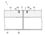
まず、建物の屋根Aの構造について説明する。この屋根Aは、いわゆる陸屋根であり、図2にも示すように、H型鋼からなる縦方向に延びる梁B1及び横方向に延びる梁B2と、多数のALCパネルC1〜C4(図には4枚のみ示す)とを組み合わせて構成されている。梁B1と梁B2とは略水平に延び、互いに直交している。 First, the structure of the roof A of the building will be described. This roof A is a so-called flat roof, and as shown in FIG. 2, a beam B1 made of H-shaped steel and a beam B2 extending in the horizontal direction, and a number of ALC panels C1 to C4 (four in the figure). Only shown). The beams B1 and B2 extend substantially horizontally and are orthogonal to each other.
ALCパネルC1〜C4は互いに同じ形状とされており、略長方形の板状に形成されている。第1ALCパネルC1、第2ALCパネルC2、第3ALCパネルC3及び第4ALCパネルC4は、互いの角部を合わせるように接近して配置されている。ALCパネルC1〜C4の縁部間の寸法は20mm程度に設定されている。ALCパネルC1〜C4の縁部間には、目地鉄筋Dが配設されている。また、ALCパネルC1〜C4の縁部間にはモルタルEが充填されており、目地鉄筋DはモルタルEに埋設されている。 The ALC panels C1 to C4 have the same shape, and are formed in a substantially rectangular plate shape. The first ALC panel C1, the second ALC panel C2, the third ALC panel C3, and the fourth ALC panel C4 are arranged close to each other so as to match each other's corners. The dimension between the edges of the ALC panels C1 to C4 is set to about 20 mm. Joint reinforcement D is disposed between the edges of the ALC panels C1 to C4. Moreover, the mortar E is filled between the edges of the ALC panels C1 to C4, and the joint reinforcement D is embedded in the mortar E.
また、ALCパネルC1〜C4の長手方向両端部の下、及び幅方向両端部の下には、梁B1及び梁B2が位置しており、ALCパネルC1〜C4の周縁部は梁B1及び梁B2によって支持されている。ALCパネルC1〜C4の梁B1及び梁B2による支持幅は、約40mm以上に設定されている。 The beams B1 and B2 are located below both ends in the longitudinal direction of the ALC panels C1 to C4 and below both ends in the width direction. The peripheral portions of the ALC panels C1 to C4 are the beams B1 and B2. Is supported by. The support width of the ALC panels C1 to C4 by the beams B1 and B2 is set to about 40 mm or more.
第1〜第4ALCパネルC1〜C4の上には、塩化ビニル系材料からなる屋上防水シートSが設けられている。 A rooftop waterproof sheet S made of a vinyl chloride material is provided on the first to fourth ALC panels C1 to C4.
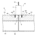
次に、太陽光発電モジュール100の架台10の構造について説明する。図3及び図4に示すように、架台10は、上下方向に延びる中空状の柱状部材11と、柱状部材11の下端部に設けられたフランジ12と、上端部に設けられた板材13と、太陽光発電モジュール100が取り付けられるボルト14とを備えている。
Next, the structure of the
柱状部材11は、上下両端が開放した鋼管で構成されている。柱状部材11の外径は例えば100mm程度であり、長さは例えば200mm程度である。フランジ12は、柱状部材11の下端部の周縁から径方向外方へ延びており、このフランジ12を構成する板材と柱状部材11を構成する鋼管とは全周に亘って溶接されている。また、柱状部材11の下端部は、フランジ12を構成する板材で覆われておらず、全体が開放されている。
The
板材13は、柱状部材11の上端部を閉塞するためのものであり、柱状部材11の外径と略同じ径を持つ円盤状に形成されている。板材13の全周が柱状部材11に溶接されている。
The
ボルト14は、板材13に固定されている。すなわち、板材13の略中央部には、ボルト14の軸部分が挿通する貫通孔13aが形成されている。ボルト14は、柱状部材11の内側から貫通孔13aに挿通した状態となっている。この状態で、ボルト14の頭部の全周が板材13の貫通孔13aの周縁部に溶接されている。
The
上記柱状部材11の内面及び外面、フランジ12の上面及び下面、板材13の上面及び下面には、塩化ビニルコーティングが施されている。この塩化ビニルコーティングは、例えば、柱状部材11、フランジ12及び板材13を流動状態の塩化ビニルが入った槽の中に浸けることによって施された、いわゆるディッピング塗装である。
Vinyl chloride coating is applied to the inner and outer surfaces of the
架台10は、図7にも示すように、フランジ12が上記第1〜第4ALCパネルC1〜C4にビス(タッピングビス)F1〜F4により締結されることにより、屋根に固定されるようになっている。フランジ12には、第1ALCパネルC1の孔101,101(図5に示す)に挿入される2本のビスF1,F1が挿通する第1ビス孔12a,12a(図4に示す)が形成され、第2ALCパネルC2の孔102,102(図5に示す)に挿入される2本のビスF2,F2が挿通する第2ビス孔12b,12b(図4に示す)が形成され、第3ALCパネルC3の孔103,103(図5に示す)に挿入される2本のビスF3,F3が挿通する第3ビス孔12c,12c(図4に示す)が形成され、第4ALCパネルC4の孔104,104(図5に示す)に挿入される2本のビスF4,F4が挿通する第4ビス孔12d,12d(図4に示す)が形成されている。
As shown in FIG. 7, the
第1ビス孔12a,12aは、フランジ12の周方向に間隔をあけて形成されている。第1ビス孔12a,12aの中心間距離は、60mm程度に設定されている。このように第1ビス孔12a,12aの間隔をあけているのは、ビス孔12a,12aを近づけすぎるとビス孔12a,12aにビスF1,F1を挿通してALCパネルC1にねじ込んでいったときにALCパネルC1が割れやすくなってしまうためである。つまり、ALCパネルC1に割れが起こらない程度に第1ビス孔12a,12aは離れていればよく、例えば50mm程度であってもよい。また、第1ビス孔12a,12aは、フランジ12における径方向中央部よりも外側領域に設けられている。
The first screw holes 12 a and 12 a are formed with a gap in the circumferential direction of the
第2ビス孔12b,12bも、第1ビス孔12a,12aと同様に間隔をあけて形成されている。第1ビス孔12a,12aと第2ビス孔12b,12bとの間隔は、第1ビス孔12a,12aの中心間距離よりも広く設定されている。
The second screw holes 12b and 12b are also formed at intervals similar to the
第3ビス孔12c,12c及び第4ビス孔12d,12dも、第1ビス孔12a,12a及び第2ビス孔12b,12bと同様に設けられている。
The
第1ビス孔12a,12aと第4ビス孔12d,12dとは、柱状部材11の中心を対称の中心とする点対称であり、第2ビス孔12b,12bと第3ビス孔12c,12cとも、柱状部材11の中心を対称の中心とする点対称である。
The
また、第1ビス孔12a,12aは、第1ALCパネルC1の縁部から50mm以上内側に位置するように配置されている。このように第1ビス孔12a,12aの位置を設定しているのは、ビスF1,F1(図7に示す)をALCパネルC1にねじ込んでいったときにビスF1,F2がALCパネルC1の縁部に接近しすぎているとALCパネルC1が割れやすくなるからである。つまり、ALCパネルC1に割れが起こらない程度に第1ビス孔12a,12aがALCパネルC1の縁部から離れていればよい。第2〜第4ビス孔12b〜12dも同様である。
Further, the
上記ビスF1〜F4は、ALCパネルC1〜C4に予め形成された孔101〜104(図5に示す)にそれぞれ挿入されたプラスチックアンカー80にねじ込まれるようになっている。プラスチックアンカー80は、従来からコンクリートにビスをねじ込む際に使用されているものなので詳細な説明は省略する。
The screws F1 to F4 are screwed into plastic anchors 80 respectively inserted into
ALCパネルC1〜C4の孔101〜104の深さは、図6に示すように、ALCパネルC1〜C4の厚み方向中途部に達する深さであり、孔101〜104は貫通していない。ビスF1〜F4は、その先端がALCパネルC1〜C4の孔101〜104の底部近傍に位置するまでねじ込まれるようになっている。
As shown in FIG. 6, the depths of the
図4に示すように、第1ビス孔12a,12aと第3ビス孔12c,12cとの間には、第1貫通孔12e,12eが形成されている。これら第1貫通孔12e,12eはフランジ12の周方向に間隔をあけて配置されている。また、第1貫通孔12e,12eは、第1ビス孔12a,12a及び第2ビス孔12b,12bよりも柱状部材11の中心に近い部分に開口している。
As shown in FIG. 4, first through
第2ビス孔12b,12bと第4ビス孔12d,12dとの間には、第2貫通孔12f,12fが第1貫通孔12e,12eと同様に形成されている。
Between the second screw holes 12b and 12b and the
上記第1貫通孔12e,12e及び第2貫通孔12f,12fには、図示しないが、他の構造の屋根に架台10を固定する際に用いられるビスが挿通するようになっている。
The first through
上記架台10は、図1に示すように防水部材40によって被覆されるようになっている。防水部材40は、図9にも示すように、柱状部材11の外面を覆う筒状部41と、フランジ12の上面を覆う板状部42とを備えている。防水部材40は、全体が塩化ビニル系シートで構成されている。
The
次に、上記架台10を用いて太陽光発電モジュール100を既存の建物の屋上に固定する場合について説明する。
Next, the case where the photovoltaic
まず、屋根Aの屋上防水シートSの一部を剥ぐ。屋上防水シートSを剥ぐ部位は、架台10の固定部位であり、第1〜第4ALCパネルC1〜C4の角部に対応する部位である。屋上防水シートSを剥ぐ範囲は、架台10のフランジ12よりも大きな範囲である。
First, a part of the rooftop waterproof sheet S on the roof A is peeled off. The site where the rooftop waterproof sheet S is peeled off is a fixed site of the
その後、図5及び図6に示すように、第1〜第4ALCパネルC1〜C4にビスF1〜F4をねじ込むための孔101〜104を形成する。この孔101〜104の位置は、上述したように、第1〜第4ALCパネルC1〜C4の縁部から内側に50mm程度離れているので第1〜第4ALCパネルC1〜C4の割れは起こらない。
Thereafter, as shown in FIGS. 5 and 6, holes 101 to 104 for screwing screws F1 to F4 are formed in the first to fourth ALC panels C1 to C4. As described above, since the positions of the
その後、架台10を第1〜第4ALCパネルC1〜C4の上に置き、ビス孔12a〜12dを第1〜第4ALCパネルC1〜C4の孔101〜104に合わせる。この状態で、架台10の柱状部材11の開放部分が 第1〜第4ALCパネルC1〜C4の角部と一致、角部が開放部分の内方に位置することになる。
Thereafter, the
しかる後、図2、図7及び図8に示すように、ビス孔12a〜12dにビスF1〜F4を挿通して第1〜第4ALCパネルC1〜C4の孔101〜104内のプラスチックアンカー80に挿入し、ねじ込む。ビスF1〜F4の先端が第1〜第4ALCパネルC1〜C4の厚み方向中途部に達したところで架台10が第1〜第4ALCパネルC1〜C4に固定された状態となる。これが架台固定工程である。固定状態の架台10の真下には、目地鉄筋Dが位置することになる。
After that, as shown in FIGS. 2, 7 and 8, the screws F1 to F4 are inserted into the screw holes 12a to 12d to the plastic anchors 80 in the
このようにビスF1〜F4を屋根Aの上からねじ込むようにしているので、天井内装材や断熱材等を取り去る必要はなく、大規模な改修工事を行わずに済む。 Since the screws F1 to F4 are screwed from the top of the roof A in this way, it is not necessary to remove the ceiling interior material, the heat insulating material, and the like, and it is not necessary to perform a large-scale repair work.
その後、屋上防水シートSを架台10のフランジ12の上面に融着する。このとき、フランジ12の上面は塩化ビニルコーティングされているので、屋上防水シートSとの融着性は高い。
Thereafter, the rooftop waterproof sheet S is fused to the upper surface of the
その後、図9に示すように、防水部材40を架台10に装着する。すなわち、防水部材40により柱状部材11の外面を覆い、防水部材40の板状部42を屋上防水シートSの上面に重ねる。防水部材40の板状部42は屋上防水シートSの上面に融着する。これにより、防水部材40と屋上防水シートSとの間がシールされる。
Thereafter, as shown in FIG. 9, the
図1に示すように、ボルト14の軸は防水部材40の上面から上方へ突出する。このとき、柱状部材11の外面及びフランジ12の上面は塩化ビニルでコーティングされているので、防水部材40を融着させることができ、高いシール性が得られる。尚、図示しないが、防水部材40をバンドによって柱状部材11に縛るようにしてもよい。
As shown in FIG. 1, the shaft of the
上記のようにして固定された架台10のボルト14に太陽光発電モジュール100を固定する。これが屋上設置物固定工程である。
The photovoltaic
以上説明したように、この実施形態にかかる屋上設置物の固定方法によれば、架台10のビスF1〜F4が第1〜第4ALCパネルC1〜C4の厚み方向中途部に達する深さまでしか挿入されないので、これらALCパネルC1〜C4に貫通孔を形成することなく、架台10をALCパネルC1〜C4に固定することが可能になる。これにより、天井内装材や断熱材等を取り去ることなく施工することが可能になる。
As described above, according to the method for fixing the rooftop installation according to this embodiment, the screws F1 to F4 of the
さらに、ALCパネルC1〜C4に貫通孔を形成しないので、従来例のものに比べてALCパネルC1〜C4自体の強度低下が防止される。 Furthermore, since no through holes are formed in the ALC panels C1 to C4, a decrease in strength of the ALC panels C1 to C4 itself is prevented as compared to the conventional example.
しかも、太陽光発電モジュール100の荷重は第1〜第4ALCパネルC1〜C4に分散して作用することになる。
Moreover, the load of the photovoltaic
したがって、室内側で大規模な改修工事を必要とせずに施工でき、さらに、設置後におけるALCパネルC1〜C4の割れを未然に防止できる。 Therefore, it can be constructed without requiring a large-scale renovation work indoors, and further, cracking of the ALC panels C1 to C4 after installation can be prevented.
また、架台10の柱状部材11の開放部分を、4枚のALCパネルC1〜C4の角部と一致させたので、各ALCパネルC1〜C4の角部にかかる荷重を低減して、ALCパネルC1〜C4をより一層割れにくくすることができる。
Moreover, since the open part of the
尚、上記実施形態では、架台10を第1〜第4ALCパネルC1〜C4の角部に一致するように固定した場合について説明したが、これに限らず、例えば、図10に示す変形例のように、第1ALCパネルC1と第2ALCパネルC2との合わせ部に固定するようにしてもよい。この変形例では、架台10の柱状部材11の開放部分が、第1ALCパネルC1と第2ALCパネルC2との合わせ部に位置するようにする。これにより、ALCパネルC1,C2の縁部にかかる荷重を低減できるので、大きな荷重が作用した場合であってもALCパネルC1,C2を割れにくくすることができる。
In the above embodiment, the case where the
また、架台10に形成するビス孔の数は上記した数に限られるものではなく、任意に設定することができる。
Further, the number of screw holes formed in the
また、ビスF1〜F4以外にも、例えばボルトやナット等の固定具を用いて架台10を固定するようにしてもよい。
Moreover, you may make it fix the
以上説明したように、本発明にかかる屋上設置物の固定方法は、例えば、既存の建物の屋上に屋上設置物を固定する場合に適用できる。 As described above, the method for fixing a rooftop installation according to the present invention can be applied to, for example, fixing a rooftop installation on the roof of an existing building.
10 架台
11 柱状部材
12 フランジ
14 ボルト
40 防水部材
100 太陽光発電モジュール(屋上設置物)
A 屋根
B1,B2 梁
C1〜C4 第1〜第4ALCパネル
D 目地鉄筋
E モルタル
F1〜F4 ビス(固定具)
DESCRIPTION OF
A Roof B1, B2 Beams C1-C4 1st-4th ALC panel D Joint reinforcement E Mortar F1-F4 Screw (fixing tool)
Claims (5)
第1ALCパネルと、該第1ALCパネルに隣接する第2ALCパネルとの接合部分には鉄筋を配設し、上記架台を上記鉄筋の真上に配置し、上記架台の基部を、上記第1ALCパネルと上記第2ALCパネルとに、これらパネルの厚み方向中途部に達する深さまで挿入した固定具を用いて固定する架台固定工程と、
上記架台に上記屋上設置物を固定する屋上設置物固定工程とを備えていることを特徴とする屋上設置物の固定方法。 In the fixing method of fixing the rooftop installation using the gantry to the ALC panel that constitutes the roof,
A reinforcing bar is disposed at a joint portion between the first ALC panel and the second ALC panel adjacent to the first ALC panel, the frame is disposed immediately above the reinforcing bar, and the base of the frame is connected to the first ALC panel. A pedestal fixing step of fixing to the second ALC panel using a fixture inserted to a depth reaching the middle part in the thickness direction of these panels;
A rooftop installation fixing method comprising: a rooftop installation fixing process for fixing the rooftop installation to the gantry.
架台は、上下方向に延びる中空状の柱状部材を備えたものであり、該柱状部材の下端部は開放され、該下端部にALCパネルへの固定用フランジが設けられ、
架台固定工程では、上記柱状部材の開放部分が第1ALCパネルと第2ALCパネルとの合わせ部に位置するように架台を配置し、上記フランジを両パネルに固定することを特徴とする屋上設置物の固定方法。 In the fixing method of the rooftop installation thing of Claim 1,
The gantry is provided with a hollow columnar member extending in the vertical direction, the lower end portion of the columnar member is opened, and a flange for fixing to the ALC panel is provided at the lower end portion,
In the gantry fixing step, the gantry is arranged so that the open portion of the columnar member is located at the joining portion of the first ALC panel and the second ALC panel, and the flange is fixed to both panels. Fixing method.
少なくとも4枚の略矩形状のALCパネルが互いの角部を合わせるように接近して配置されており、
架台固定工程では、架台の柱状部材の開放部分を上記4枚のALCパネルの角部と一致させた状態で該架台を固定することを特徴とする屋上設置物の固定方法。 In the fixing method of the rooftop installation thing of Claim 2,
At least four substantially rectangular ALC panels are arranged close to each other so that their corners are aligned,
In the gantry fixing step, the gantry is fixed in a state where the open portions of the columnar members of the gantry are aligned with the corners of the four ALC panels.
第1ALCパネルと、該第1ALCパネルに隣接する第2ALCパネルとの接合部分に配設された鉄筋の真上に上記架台が配置され、上記架台の基部が、上記第1ALCパネルと上記第2ALCパネルとに、これらパネルの厚み方向中途部に達する深さまで挿入した固定具を用いて固定され、
上記架台に上記屋上設置物が固定されていることを特徴とする屋上設置物の固定構造。 In the fixing structure of the rooftop installation that fixes the rooftop installation using a mount to the ALC panel that constitutes the roof,
The gantry is disposed directly above the reinforcing bar disposed at the joint between the first ALC panel and the second ALC panel adjacent to the first ALC panel, and the base of the gantry is the first ALC panel and the second ALC panel. In addition, it is fixed using a fixture inserted to a depth that reaches the middle of the thickness direction of these panels,
A structure for fixing a rooftop installation object, wherein the rooftop installation object is fixed to the frame.
架台は、上下方向に延びる中空状の柱状部材を備えたものであり、該柱状部材の下端部は開放され、該下端部にALCパネルへの固定用フランジが設けられ、
上記柱状部材の開放部分を、第1ALCパネルと第2ALCパネルとの合わせ部に位置付け、上記フランジが両パネルに固定されていることを特徴とする屋上設置物の固定構造。 In the fixed structure of the rooftop installation thing of Claim 4 ,
The gantry is provided with a hollow columnar member extending in the vertical direction, the lower end portion of the columnar member is opened, and a flange for fixing to the ALC panel is provided at the lower end portion,
A structure for fixing a rooftop installation, wherein the open portion of the columnar member is positioned at a joint portion between the first ALC panel and the second ALC panel, and the flange is fixed to both panels.
Priority Applications (1)
| Application Number | Priority Date | Filing Date | Title |
|---|---|---|---|
| JP2010245421A JP5643608B2 (en) | 2010-11-01 | 2010-11-01 | Fixing method and structure for rooftop installation |
Applications Claiming Priority (1)
| Application Number | Priority Date | Filing Date | Title |
|---|---|---|---|
| JP2010245421A JP5643608B2 (en) | 2010-11-01 | 2010-11-01 | Fixing method and structure for rooftop installation |
Publications (2)
| Publication Number | Publication Date |
|---|---|
| JP2012097450A JP2012097450A (en) | 2012-05-24 |
| JP5643608B2 true JP5643608B2 (en) | 2014-12-17 |
Family
ID=46389674
Family Applications (1)
| Application Number | Title | Priority Date | Filing Date |
|---|---|---|---|
| JP2010245421A Active JP5643608B2 (en) | 2010-11-01 | 2010-11-01 | Fixing method and structure for rooftop installation |
Country Status (1)
| Country | Link |
|---|---|
| JP (1) | JP5643608B2 (en) |
Families Citing this family (3)
| Publication number | Priority date | Publication date | Assignee | Title |
|---|---|---|---|---|
| JP6000165B2 (en) * | 2013-03-01 | 2016-09-28 | Jfe建材株式会社 | Deck foundation roof equipment installation foundation and construction method |
| JP6166917B2 (en) * | 2013-03-19 | 2017-07-19 | ロンシール工業株式会社 | Support base fixing structure |
| JP7271829B2 (en) * | 2018-10-11 | 2023-05-12 | トヨタホーム株式会社 | Support hardware fixing structure and support hardware fixing method |
Family Cites Families (1)
| Publication number | Priority date | Publication date | Assignee | Title |
|---|---|---|---|---|
| JPH04330146A (en) * | 1991-02-12 | 1992-11-18 | Sekisui Chem Co Ltd | Fixing method for object installed on roof or floor |
-
2010
- 2010-11-01 JP JP2010245421A patent/JP5643608B2/en active Active
Also Published As
| Publication number | Publication date |
|---|---|
| JP2012097450A (en) | 2012-05-24 |
Similar Documents
| Publication | Publication Date | Title |
|---|---|---|
| JP6368787B2 (en) | Three-dimensional lightweight steel frame formed by bidirectional continuous double beams | |
| KR100991851B1 (en) | Earthquake retrofit structure for brick wall and construction method thereof | |
| KR101615126B1 (en) | Outer insulation system and installation method of outer wall using it | |
| JP2007211399A (en) | Solar panel fixing structure | |
| KR101272601B1 (en) | A joint structure for sculpture of rooftop | |
| JP2007224626A (en) | Roof reforming structure for flat roof building, and method of constructing the same | |
| JP5643608B2 (en) | Fixing method and structure for rooftop installation | |
| JP5591008B2 (en) | Rooftop waterproofing method | |
| JP4653578B2 (en) | Building member mounting hardware, building member mounting structure, and building member mounting method | |
| KR20120107365A (en) | Method for installing alc panel to concrete slab | |
| JP5869273B2 (en) | Mounting method of base support | |
| JP6115518B2 (en) | How to install the support legs of the solar cell module mount on the flat roof | |
| JP5319401B2 (en) | Column base protection structure | |
| KR101462841B1 (en) | Brick Spacers Intergrated Insulating Material and Masonry Wall Constructing Method Using the same | |
| KR20090006687U (en) | Prefabricated adiabatic panel | |
| KR101569242B1 (en) | Panel and Heat insulator construction method thereof | |
| KR101143553B1 (en) | Construction method for building remodeling by using pc panel for building remodeling, and connecting structure for remodeling pc panel | |
| KR20130039454A (en) | Angle bracket for fixing exterior of insulation panel and that construction method | |
| JP2009270287A (en) | Exterior wall repairing method | |
| JP2007224586A (en) | Composite structural building and method of constructing composite structural building | |
| JP6986829B2 (en) | Rooftop waterproof construction method | |
| CN106351393B (en) | Prefabricated panel and wall body structure | |
| JP7193368B2 (en) | roof panel | |
| JP6998137B2 (en) | Fireproof building structure and receiving members | |
| JP7040755B2 (en) | Outer wall structure |
Legal Events
| Date | Code | Title | Description |
|---|---|---|---|
| A621 | Written request for application examination |
Free format text: JAPANESE INTERMEDIATE CODE: A621 Effective date: 20130819 |
|
| RD02 | Notification of acceptance of power of attorney |
Free format text: JAPANESE INTERMEDIATE CODE: A7422 Effective date: 20130819 |
|
| A977 | Report on retrieval |
Free format text: JAPANESE INTERMEDIATE CODE: A971007 Effective date: 20140325 |
|
| A131 | Notification of reasons for refusal |
Free format text: JAPANESE INTERMEDIATE CODE: A131 Effective date: 20140805 |
|
| A521 | Request for written amendment filed |
Free format text: JAPANESE INTERMEDIATE CODE: A523 Effective date: 20140909 |
|
| TRDD | Decision of grant or rejection written | ||
| A01 | Written decision to grant a patent or to grant a registration (utility model) |
Free format text: JAPANESE INTERMEDIATE CODE: A01 Effective date: 20141014 |
|
| A61 | First payment of annual fees (during grant procedure) |
Free format text: JAPANESE INTERMEDIATE CODE: A61 Effective date: 20141031 |
|
| R150 | Certificate of patent or registration of utility model |
Ref document number: 5643608 Country of ref document: JP Free format text: JAPANESE INTERMEDIATE CODE: R150 |
|
| R250 | Receipt of annual fees |
Free format text: JAPANESE INTERMEDIATE CODE: R250 |
|
| R250 | Receipt of annual fees |
Free format text: JAPANESE INTERMEDIATE CODE: R250 |
|
| R250 | Receipt of annual fees |
Free format text: JAPANESE INTERMEDIATE CODE: R250 |