JP5642403B2 - Molding method and molded body of plate workpiece - Google Patents
Molding method and molded body of plate workpiece Download PDFInfo
- Publication number
- JP5642403B2 JP5642403B2 JP2010062625A JP2010062625A JP5642403B2 JP 5642403 B2 JP5642403 B2 JP 5642403B2 JP 2010062625 A JP2010062625 A JP 2010062625A JP 2010062625 A JP2010062625 A JP 2010062625A JP 5642403 B2 JP5642403 B2 JP 5642403B2
- Authority
- JP
- Japan
- Prior art keywords
- plate
- workpiece
- shim
- bending
- recess
- Prior art date
- Legal status (The legal status is an assumption and is not a legal conclusion. Google has not performed a legal analysis and makes no representation as to the accuracy of the status listed.)
- Active
Links
Images


Description
本発明は、板状ワークの成形方法および成形体に関する。 The present invention relates to a method for forming a plate-shaped workpiece and a molded body.
従来、民間航空機の胴体部に適用される外板等はアルミニウム合金板が用いられて軽量化が図られており、さらなる軽量化のために減肉加工が施されている。そして、航空機の胴体形状となる外板は、所定の曲率をもった形状で成形されており、一般的には平板をプレス曲げした後にケミカルミーリングで減肉加工を行う方法により成形されている。また、他の成形方法として、例えば、特許文献1、2に開示されている方法がある。
Conventionally, an outer plate or the like applied to a fuselage portion of a commercial aircraft has been made lighter by using an aluminum alloy plate, and has been subjected to thickness reduction processing for further weight reduction. And the outer plate | board used as the fuselage | body shape of an aircraft is shape | molded by the shape with a predetermined curvature, and is generally shape | molded by the method of carrying out the thickness reduction process by chemical milling after press-bending a flat plate. Moreover, as another shaping | molding method, there exists the method currently disclosed by
特許文献1は、平板状態で成形した後に、機械加工で減肉加工を実施する方法について記載したものである。
特許文献2には、板状ワークにショット材を投射して所定の曲率を与える板状ワークの成形方法であって、所定の曲率を与える成形を行う前の板状ワークに、その板状ワークが成形後に製品として機能するために必要となる板厚加工による前加工を行う工程と、その前加工を施した板状ワークにショット材を投射して所定の曲率を与える工程と、を含む成形方法について提案されている。
Patent Document 1 describes a method of performing a thinning process by machining after being molded in a flat plate state.
しかしながら、従来の一般的な成形方法においては、平板をプレス曲げした後のケミカルミーリングは加工時間が長く、加工溶液などの産業廃棄物が発生するという問題があった。
また、特許文献1では、曲率を有する外板を機械加工するため、ボールエンドミルを使用する必要があり、加工効率が低下するという不具合が生じていた。
また、特許文献2では、ショット材を投射して成形する方法であり、加工精度に再現性をもたせるのが困難であり、修正加工が必要となっていた。
したがって、上述したような問題のない成形方法が求められており、その点で改良の余地があった。
However, in the conventional general molding method, chemical milling after press-bending a flat plate has a problem that processing time is long and industrial waste such as processing solution is generated.
Moreover, in patent document 1, in order to machine the outer plate | board which has a curvature, it was necessary to use a ball end mill, and the malfunction that processing efficiency fell occurred.
Further, in
Therefore, there is a need for a molding method that does not have the problems described above, and there is room for improvement in that respect.
本発明は、上述する問題点に鑑みてなされたもので、加工効率の向上を図ることができるうえ、産業廃棄物の発生を抑えることができる板状ワークの成形方法および成形体を提供することを目的とする。
また、本願発の別の目的は、成形精度に優れた再現性をもたせることができる板状ワークの成形方法および成形体を提供することである。
The present invention has been made in view of the above-described problems, and provides a method for forming a plate-like workpiece and a molded body that can improve the processing efficiency and suppress the generation of industrial waste. With the goal.
Another object of the present invention is to provide a method for forming a plate-like workpiece and a molded body that can provide reproducibility with excellent forming accuracy.
上記目的を達成するため、本発明に係る板状ワークの成形方法では、板状ワークの凹面側の面方向に所定の間隔をおいて複数の凹部を設ける工程と、プレス又はロール曲げにより板状ワークを一方の面から他方の面の側へ曲げる工程と、凹部に対応する形状で、且つ板状ワークよりヤング率が小さいシムを、凹部に挿入する工程と、を有し、シムが挿入された板状ワークの凹面にシート状の保護材が配置されていることを特徴としている。 In order to achieve the above object, in the method for forming a plate-like workpiece according to the present invention, a step of providing a plurality of recesses at a predetermined interval in the surface direction on the concave surface side of the plate-like workpiece, and a plate shape by pressing or roll bending. a step of bending the workpiece from one side toward the other surface, in a shape corresponding to the recess, and a shim Young's modulus is smaller than the plate workpiece, possess the steps of inserting into the recess, the shim is inserted A sheet-like protective material is disposed on the concave surface of the plate-like workpiece .
また、本発明に係る成形体では、上述した板状ワークの成形方法によって製造されたことを特徴としている。 Further, the molded body according to the present invention is characterized by being manufactured by the above-described method for molding a plate-like workpiece.
本発明では、板状ワークの凹面側の面方向に所定の間隔をおいて凹部を設ける減肉加工を平板の状態で行うことができるので、通常の3軸機械加工装置でエンドミルを使用した機械加工が可能となる。しかも、大径のエンドミルを使用できるので、機械加工時間の短縮が図れ、加工効率を向上させることができる。
また、減肉加工した板状ワークに対してプレス機、或いはロール曲げ機を使用して曲げ加工を行うため、ショット材を投射する従来の方法に比べて、成形精度の再現性に優れ、修正加工が不要となり、成形時間の短縮を図ることができる。
さらに、機械加工による減肉であるので、ケミカルミーリングを使用する場合のように加工溶液の廃液が無く、しかもエンドミルの切削によって生じる切屑がスクラップとして再利用も可能であることから、産業廃棄物の発生を抑えられる利点がある。
In the present invention, since the thinning process in which the concave portions are provided at predetermined intervals in the surface direction on the concave surface side of the plate-like workpiece can be performed in a flat plate state, a machine using an end mill in a normal three-axis machining apparatus Processing becomes possible. Moreover, since a large-diameter end mill can be used, the machining time can be shortened and the machining efficiency can be improved.
In addition, because the plate-shaped workpiece with reduced thickness is bent using a press or roll bending machine, it has excellent reproducibility of molding accuracy and correction compared to the conventional method of projecting shot material. No processing is required, and the molding time can be shortened.
Furthermore, since it is reduced by machining, there is no waste of processing solution as in the case of chemical milling, and chips generated by end mill cutting can be reused as scrap. There is an advantage that generation can be suppressed.
また、本発明に係る板状ワークの成形方法では、凹部に対応する形状で、且つ板状ワークよりヤング率が小さいシムを、凹部に挿入する工程を有していることが好ましい。
本発明では、板状ワークに設けた凹部に板状ワークよりヤング率が小さいシムを挿入することにより、曲げ加工時にシムが板状ワークの曲げに追従して弾性変形により湾曲するため、板状ワークの成形後の曲げ半径を大きくすることが可能となる。そのため、凹部を形成する減肉部での曲げ半径が凹部でない一般部の曲げ半径に近づくので、減肉部と一般部との曲げ形状に差が無くなり、多角形状に湾曲することがなく、滑らかな凹面形状を得ることができる。
Moreover, it is preferable that the method for forming a plate-like workpiece according to the present invention includes a step of inserting a shim having a shape corresponding to the recess and having a Young's modulus smaller than that of the plate-like workpiece into the recess.
In the present invention, by inserting a shim having a Young's modulus smaller than that of the plate-like workpiece into the recess provided in the plate-like workpiece, the shim follows the bending of the plate-like workpiece at the time of bending, so that it is bent by elastic deformation. It is possible to increase the bending radius after the workpiece is formed. Therefore, the bending radius at the thinned portion that forms the concave portion approaches the bending radius of the general portion that is not the concave portion, so there is no difference in the bending shape between the thinned portion and the general portion, and there is no need to bend into a polygonal shape. A concave shape can be obtained.
また、本発明では、板状ワークを曲げたときに、凹部に対するシムのマイナス公差によって、シムの弾性変形が吸収されるので、シムと凹部との密着性が高められる、そのため、曲げ加工時であっても凹部からシムが外れることを防ぐことができる。 Further, in the present invention, when a plate-shaped workpiece is bent, the shim's elastic deformation is absorbed by the shim's minus tolerance with respect to the recess, so that the adhesion between the shim and the recess is improved. Even if it exists, it can prevent that a shim remove | deviates from a recessed part.
また、本発明に係る板状ワークの成形方法では、シムは、加工物よりもヤング率が低いことが望ましく、ヤング率が7〜10GPaのベークライトであることがより好ましい。
本発明では、ヤング率が7〜10GPaのベークライトからなるシムを用いることで凹部に対してより優れた密着性能を得ることができる。つまり、シムの曲がりが少なく凹部に対する追従性が悪くなって密着性が低下したり、反対にシムが曲がり過ぎて凹部から抜け出してしまうといった不具合を抑制することができる。
In the method for forming a plate-like workpiece according to the present invention, the shim preferably has a Young's modulus lower than that of the workpiece, and more preferably a bakelite having a Young's modulus of 7 to 10 GPa.
In the present invention, by using a shim made of bakelite having a Young's modulus of 7 to 10 GPa, better adhesion performance with respect to the recess can be obtained. That is, it is possible to suppress problems such that the shim is less bent and the followability to the recess is deteriorated and the adhesion is deteriorated, or on the contrary, the shim is excessively bent and escapes from the recess.
また、本発明に係る板状ワークの成形方法では、凹部は、階段状に形成されていることが好ましい。
本発明では、シムにも凹部の階段状の段差部に対応する段部を設けることで、この段差部分での密着性をより一層高めることができ、追従性を高めることができ、板状ワークを滑らかに曲げることができる。
In the method for forming a plate-like workpiece according to the present invention, it is preferable that the recess is formed in a step shape.
In the present invention, by providing the shim with a step corresponding to the stepped stepped portion of the recess, the adhesion at the stepped portion can be further enhanced, the followability can be improved, and the plate-like workpiece Can be bent smoothly.
本発明の板状ワークの成形方法および成形体によれば、板状ワークに凹部を設ける減肉加工を平板の状態で行うことができるので、通常の3軸機械加工装置でエンドミルを使用した機械加工が可能となるから、加工効率の向上を図ることができるうえ、ケミカルミーリングによる減肉加工に比べて産業廃棄物の発生を抑えることができる。
また、曲げ加工においてもプレス又はロール曲げによる機械加工となるので、成形精度に優れた再現性をもたせることができる利点がある。
According to the plate-shaped workpiece forming method and the molded body of the present invention, the thinning process for providing the concave portion in the plate-shaped workpiece can be performed in a flat plate state, and therefore a machine using an end mill in a normal three-axis machining apparatus Since the processing becomes possible, the processing efficiency can be improved and the generation of industrial waste can be suppressed as compared with the thickness reduction processing by chemical milling.
Further, since bending is mechanical processing by press or roll bending, there is an advantage that reproducibility with excellent molding accuracy can be provided.
以下、本発明の実施の形態による板状ワークの成形方法および成形体について、図面に基づいて説明する。かかる実施の形態は、本発明の一態様を示すものであり、この発明を限定するものではなく、本発明の技術的思想の範囲内で任意に変更可能である。また、以下の図面においては、各構成をわかりやすくするために、実際の構造と各構造における縮尺や数等が異なっている。 Hereinafter, a method for forming a plate-like workpiece and a formed body according to embodiments of the present invention will be described with reference to the drawings. This embodiment shows one aspect of the present invention, and does not limit the present invention, and can be arbitrarily changed within the scope of the technical idea of the present invention. Moreover, in the following drawings, in order to make each structure easy to understand, an actual structure and a scale, a number, and the like in each structure are different.
(第1の実施の形態)
図1および図2に示す符号1は、例えば航空機の胴体部分に用いられる円筒形の外板の一部(以下、「板状ワーク1」という)であり、本第1の実施の形態の成形方法によって所定の曲率に曲げ加工する適用対象である。板状ワーク1は、アルミニウム合金が使用される。なお、板状ワーク1は、本願発明の「成形体」に相当する。
ここで、図1乃至図3に示す板状ワーク1において、上側を凹面1aとし、下側を凸面1bとして以下統一して説明する。
(First embodiment)
Reference numeral 1 shown in FIG. 1 and FIG. 2 is a part of a cylindrical outer plate (hereinafter referred to as “plate-like workpiece 1”) used for, for example, an aircraft fuselage, and is molded according to the first embodiment. It is an object to be bent to a predetermined curvature by a method. The plate workpiece 1 is made of an aluminum alloy. The plate-like workpiece 1 corresponds to the “molded body” of the present invention.
Here, in the plate-like workpiece 1 shown in FIGS. 1 to 3, the upper side is a
板状ワーク1の成形方法は、板状ワーク1の凹面1a側の面方向に所定の間隔をおいて複数のポケット11(凹部)を設けて減肉加工をする第1工程と、プレスによる板状ワーク1を凸面1b(一方の面)から凹面1a(他方の面)側へ曲げる曲げ加工を行う第2工程とを有している。
ポケット11は、板状ワーク1の凹面1aの所定位置に配置され、例えば平面視略四角形状をなし、上述した減肉加工の第1工程により適宜な厚さ寸法となるように形成されている。
The forming method of the plate-like workpiece 1 includes a first step in which a plurality of pockets 11 (concave portions) are provided at a predetermined interval in the surface direction on the
The
次に、板状ワーク1の成形方法についてさらに具体的に説明する。
先ず、第1工程において、図1に示す平板状態の板状ワーク1に対して例えばエンドミルを備えた通常の3軸機械加工装置を用いて、予め設定した箇所を所定深さ(厚さ寸法)により減肉加工を施し、複数のポケット11を形成する。
Next, the method for forming the plate workpiece 1 will be described more specifically.
First, in the first step, a predetermined position (thickness dimension) is set at a predetermined position using, for example, an ordinary triaxial machining apparatus equipped with an end mill for the flat plate-like workpiece 1 shown in FIG. The thinning process is performed to form a plurality of
続いて、第2工程では、図3に示すように、プレス機2の下金型21の上に第1工程で減肉加工した板状ワーク1を載置する。ここで、プレス機2は、上下一対の金型(下金型21、上金型22)を有し、固定される下金型21に対して上金型22が上下動する構造となっている。下金型21および上金型22の幅寸法は、それぞれ板状ワーク1の幅寸法よりも大きな寸法となっている。そして、下金型21には、上金型22に対応する位置に開口凹部21aが設けられている。
Subsequently, in the second step, as shown in FIG. 3, the plate-like workpiece 1 subjected to the thickness reduction processing in the first step is placed on the lower mold 21 of the
そして、板状ワーク1に対して、上金型22を下金型21側に押し込み、下金型21の上に載置させた板状ワーク1を局部的に押圧することで湾曲させる。そして、板状ワーク1を湾曲させる周方向(図3で矢印X方向)に送りつつ、上金型22による押圧する動作を順次繰り返すことで平板状の板状ワーク1に円筒曲げを施すことができ、滑らかな凹面1aを形成することができる。
Then, the
このような成形方法の具体例として、板状ワーク1として幅寸法2m、長さ寸法6m、板厚寸法t1が約4mmの形状で、2024−T3のアルミニウム合金のものを用い、局部的に板厚寸法t2が2mmとなるように、工具径50mmのエンドミルを使用して機械加工により第1工程の減肉を行い、次いでプレス機2を用いて順次第2加工となる曲げ加工により曲げ半径で約3mの円筒形状に曲げることができる。
As a specific example of such a forming method, a plate-like workpiece 1 having a width dimension of 2 m, a length dimension of 6 m, and a plate thickness dimension t1 of about 4 mm and a 2024-T3 aluminum alloy is used locally. The thickness of the first step is reduced by machining using an end mill with a tool diameter of 50 mm so that the thickness dimension t2 becomes 2 mm, and then the bending radius is obtained by bending using the
上述した本第1の実施の形態による板状ワークの成形方法および成形体では、板状ワーク1の凹面1a側の面方向に所定の間隔をおいてポケット11を設ける減肉加工を平板の状態で行うことができるので、通常の3軸機械加工装置でエンドミルを使用した機械加工が可能となる。しかも、大径のエンドミルを使用できるので、機械加工時間の短縮が図れ、加工効率を向上させることができる。
In the plate-like workpiece forming method and the molded body according to the first embodiment described above, the thinning process in which the
また、減肉加工した板状ワーク1に対してプレス機2を使用して曲げ加工を行うため、ショット材を投射する従来の方法に比べて、成形精度の再現性に優れ、修正加工が不要となり、成形時間の短縮を図ることができる。
さらに、機械加工による減肉であるので、ケミカルミーリングを使用する場合のように加工溶液の廃液が無く、しかもエンドミルの切削によって生じる切屑がスクラップとして再利用も可能であることから、産業廃棄物の発生を抑えられる利点がある。
In addition, since the plate-like workpiece 1 subjected to the thinning process is bent using the
Furthermore, since it is reduced by machining, there is no waste of processing solution as in the case of chemical milling, and chips generated by end mill cutting can be reused as scrap. There is an advantage that generation can be suppressed.
次に、本発明の板状ワークの成形方法および成形体による他の実施の形態について、添付図面に基づいて説明するが、上述の第1の実施の形態と同一又は同様な部材、部分には同一の符号を用いて説明を省略し、実施の形態と異なる構成について説明する。 Next, other embodiments of the plate-like workpiece molding method and molded body according to the present invention will be described with reference to the accompanying drawings. However, the same or similar members and parts as those of the first embodiment described above The description is omitted using the same reference numerals, and a configuration different from the embodiment will be described.
(第2の実施の形態)
図4および図5に示すように、第2の実施の形態による板状ワークの成形方法および成形体では、上述した第1の実施の形態で第1工程の後、その減肉加工により設けたポケット11に対応する形状で、且つ板状ワーク1よりヤング率が小さいシム3を挿入する工程を有するものである。なお、第2工程の曲げ加工については、上述した実施の形態と同様でプレス機2(図3参照)を用いる方法であるので、ここでは詳しい説明は省略する。
(Second Embodiment)
As shown in FIGS. 4 and 5, the plate-like workpiece molding method and molded body according to the second embodiment are provided by the thinning process after the first step in the first embodiment described above. This includes a step of inserting a
シム3としては、嵌合されるポケット11に対して密着性が高く、なじみ易い材料が良く、またヤング率が5〜25GPaである部材が好ましく、より好ましくは7〜10GPaのベークライトが良い。
そして、シム3は、ポケット11の内空寸法より僅かに小さいマイナス公差で設けられ、ポケット11に対して緩み嵌めされている。つまり、ポケット11内に嵌合されたシム3は、ポケット11に対して密着しつつ、外部から受ける力に応じて弾性変形により滑りが生じる状態となっている。
The
The
本第2の実施の形態では、シム3を設けることで、減肉加工を施していない一般部の第1板厚寸法t1(図4)と、ポケット11を設けた減肉部分の第2板厚寸法t2(図4)との差(板厚寸法差Δt)を無くした状態で、第2工程の曲げ加工を行うことができる。
In the second embodiment, by providing the
具体的には、板状ワーク1に設けたポケット11に板状ワーク1よりヤング率(例えば上述したように5〜25GPa)が小さいシム3を挿入することにより、曲げ加工時にシム3が板状ワーク1の曲げに追従して弾性変形により湾曲するため、板状ワーク1の成形後の曲げ半径を大きくすることが可能となる。
そのため、ポケット11を形成する減肉部での曲げ半径がポケット11でない一般部の曲げ半径に近づくので、減肉部と一般部との曲げ形状に差が無くなり、多角形状(板厚寸法の大きな一般部を頂点とした多角形を形成するような曲げ)に湾曲することがなく、滑らかな凹面形状を得ることができる。
Specifically, by inserting a
Therefore, since the bending radius at the thinned portion forming the
また、シム3がポケット11に対して緩み嵌めされているので、板状ワーク1を曲げたときに、ポケット11に対するシム3のマイナス公差によって、シム3の弾性変形が吸収されるので、シム3とポケット11との密着性が高められる、そのため、曲げ加工時であってもポケット11からシム3が外れることを防ぐことができる。
Further, since the
また、上述したようなヤング率が7〜10GPaのベークライトを使用することで、より優れた密着性能を得ることができる。 In addition, by using a bakelite having a Young's modulus of 7 to 10 GPa as described above, better adhesion performance can be obtained.
なお、シム3のヤング率が25GPa以上の場合には、シム3の弾性変形が小さく、曲がりが少なく、ポケット11の曲がりに対してシム3の追従性が悪くなって、両者間に隙間が発生し、密着性が低くなる。一方、シム3のヤング率が5GPa未満の場合には、シム3が曲がり過ぎてしまい、多角形形状の抑制の効果は期待できない。
In addition, when the Young's modulus of the
(第3の実施の形態)
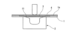
図6および図7に示すように、第3の実施の形態による板状ワークの成形方法および成形体は、上述した第2の実施の形態による成形方法のポケット11およびシム3の形状を代えた方法であって、板状ワーク1のポケット11に角部に階段状(本実施の形態では1段)の段差部11aを形成する減肉加工を行い、この段差部11aに対応する段部3aを有するシム3をポケット11に嵌合させるものである。また、減肉加工したポケット11にシム3を嵌合させた状態で、板状ワーク1の凹面1aにウレタンゴム等からなるシート状の保護材4を配置している。
なお、第2工程の曲げ加工については、上述した実施の形態と同様でプレス機2を用いる方法であるので、ここでは詳しい説明は省略する。
(Third embodiment)
As shown in FIGS. 6 and 7, the shape of the plate-like workpiece and the molded body according to the third embodiment are different from the shape of the
Note that the bending process in the second step is a method using the
この場合、ポケット11の段差部11aでシム3の段部3aの追従性が高まり、この段差部分での密着性をより一層向上させることができ、板状ワーク1を滑らかに曲げることができる。
なお、保護材4は、凹面1aに載せておくだけのものであり、曲げ加工時に曲がるシム3がポケット11から突出するのを抑える当て止めの機能をもたせている。
In this case, the followability of the
Note that the protective material 4 is merely placed on the
次に、上述した第2及び第3の実施の形態による板状ワークの成形方法および成形体による効果を裏付けるために行った試験例について以下説明する。 Next, test examples performed to support the effects of the plate-like workpiece forming method and the formed body according to the second and third embodiments described above will be described below.
本実施例では、ベークライトからなるシムをポケットに嵌合させたときの、板状ワークの曲げ加工による曲率を確認した。具体的には、FEM解析を用い、板状ワークとシムのモデルを作成し、所定の形状、大きさのポケットにシムを嵌合させた状態で、板状ワークを下記の条件で曲げて解析をし、シム毎にヤング率を変えて板状ワークの曲率を求めた。なお、解析により得られる曲率が大きい値ほど効率よく曲げることができる。 In this example, the curvature of the plate-like workpiece by bending was confirmed when a shim made of bakelite was fitted in the pocket. Specifically, FEM analysis is used to create a model of a plate-like workpiece and shim, and the plate-like workpiece is bent and analyzed under the following conditions with the shim fitted in a pocket of a predetermined shape and size. The curvature of the plate workpiece was obtained by changing the Young's modulus for each shim. In addition, it can bend efficiently, so that the value of the curvature obtained by analysis is large.
解析条件としては、板状ワーク1の第1板厚寸法t1を6.87mm、第2板厚寸法t2を2.51mmとし、板状ワーク1は、ヤング率を72Pa、ポアソン比を0.33とし、密度2.77g/cm3、降伏応力を324MPaとした弾塑性体とした。シム3の密度は1.32g/cm3とした。さらに曲げ加工の条件としては、金型と素材、素材同士の摩擦係数を0.2とし、成形速度(送り速度)を10mm/sec、送りストロークを約8.9mmとした。
As analysis conditions, the first thickness t1 of the plate-like workpiece 1 is 6.87 mm, the second thickness t2 is 2.51 mm, and the plate-like workpiece 1 has a Young's modulus of 72 Pa and a Poisson's ratio of 0.33. And an elastic-plastic body having a density of 2.77 g / cm 3 and a yield stress of 324 MPa. The density of
図8に示すように、本解析結果によると、シムのヤング率が7〜10GPaで曲率が大きくなっていることが確認できる。なお、比較するために、減肉加工がない場合(中実材)も示している。 As shown in FIG. 8, according to this analysis result, it can be confirmed that the curvature is large when the Young's modulus of the shim is 7 to 10 GPa. For comparison, the case where there is no thinning process (solid material) is also shown.
以上、本発明による板状ワークの成形方法および成形体の実施の形態について説明したが、本発明は上記の実施の形態に限定されるものではなく、その趣旨を逸脱しない範囲で適宜変更可能である。
例えば、本実施の形態では第2工程の曲げ加工にプレス機2を採用しているが、これに限定されることはなく、ロール曲げ機を用いた曲げ加工であっても良い。
As mentioned above, although the shaping | molding method of the plate-shaped workpiece and embodiment of a molded object by this invention were demonstrated, this invention is not limited to said embodiment, It can change suitably in the range which does not deviate from the meaning. is there.
For example, in the present embodiment, the
また、本実施の形態ではシム3として、ベークライトを採用しているが、この部材であることに制限されることはなく、他の部材として例えばエポキシ樹脂、不飽和ポリエステル等や、これらにガラス繊維を充填した部材であってもかまわない。
Further, in this embodiment, bakelite is adopted as the
また、シム3はポケット11に対して脱落防止を目的として両面テープ等で仮止めするようにしてもよい。要は、ポケット11に緩み嵌めされたシム3がその公差の範囲内で滑りが生じて曲げによる弾性変形が可能な状態となればよいのである。
さらに、本実施の形態ではポケット11に1段の段差部11aを設ける構成としているが、段差数は任意に設定することが可能であり、2段以上の段差部11aであってもよい。例えば、板状ワーク1の板厚寸法が大きい場合には多段の段差部とし、板厚寸法が小さい場合には1段、あるいは段差無しとすることができる。
The
Further, in the present embodiment, the
その他、本発明の趣旨を逸脱しない範囲で、上記した実施の形態における構成要素を周知の構成要素に置き換えることは適宜可能であり、また、上記した実施の形態を適宜組み合わせてもよい。 In addition, it is possible to appropriately replace the constituent elements in the above-described embodiments with well-known constituent elements without departing from the spirit of the present invention, and the above-described embodiments may be appropriately combined.
1 板状ワーク(成形体)
1a 凹面
2 プレス機
3 シム
3a 段部
4 保護材
11 ポケット(凹部)
11a 段差部
1 Plate-shaped workpiece (molded body)
1a Concave surface
11a Stepped part
Claims (5)
プレス又はロール曲げにより前記板状ワークを一方の面から他方の面の側へ曲げる工程と、
前記凹部に対応する形状で、且つ前記板状ワークよりヤング率が小さいシムを、前記凹部に挿入する工程と、
を有し、
前記シムが挿入された前記板状ワークの凹面にシート状の保護材が配置されていることを特徴とする板状ワークの成形方法。 Providing a plurality of recesses at a predetermined interval in the surface direction of the concave side of the plate-like workpiece;
Bending the plate-shaped workpiece from one surface to the other surface by pressing or roll bending;
Inserting a shim having a shape corresponding to the recess and having a Young's modulus smaller than the plate-like workpiece into the recess;
I have a,
A method for forming a plate-like workpiece, wherein a sheet-like protective material is disposed on the concave surface of the plate-like workpiece into which the shim is inserted .
Priority Applications (8)
| Application Number | Priority Date | Filing Date | Title |
|---|---|---|---|
| JP2010062625A JP5642403B2 (en) | 2010-03-18 | 2010-03-18 | Molding method and molded body of plate workpiece |
| US13/635,476 US9616479B2 (en) | 2010-03-18 | 2011-03-18 | Molding method for plate-shaped workpiece, and molded article |
| KR1020127027142A KR20120130263A (en) | 2010-03-18 | 2011-03-18 | Molding method for plate-shaped workpiece, and molded article |
| CN201180014274.0A CN102802829B (en) | 2010-03-18 | 2011-03-18 | The manufacturing process of plate workpiece and formed body |
| CA2793530A CA2793530C (en) | 2010-03-18 | 2011-03-18 | Molding method for plate-shaped workpiece, and molded article |
| PCT/JP2011/056523 WO2011115244A1 (en) | 2010-03-18 | 2011-03-18 | Molding method for plate-shaped workpiece, and molded article |
| BR112012023546A BR112012023546A2 (en) | 2010-03-18 | 2011-03-18 | molding method for plate molded workpiece, and molded article |
| EP11756427.8A EP2548667B1 (en) | 2010-03-18 | 2011-03-18 | Molding method for plate-shaped workpiece, and molded article |
Applications Claiming Priority (1)
| Application Number | Priority Date | Filing Date | Title |
|---|---|---|---|
| JP2010062625A JP5642403B2 (en) | 2010-03-18 | 2010-03-18 | Molding method and molded body of plate workpiece |
Publications (2)
| Publication Number | Publication Date |
|---|---|
| JP2011194425A JP2011194425A (en) | 2011-10-06 |
| JP5642403B2 true JP5642403B2 (en) | 2014-12-17 |
Family
ID=44873288
Family Applications (1)
| Application Number | Title | Priority Date | Filing Date |
|---|---|---|---|
| JP2010062625A Active JP5642403B2 (en) | 2010-03-18 | 2010-03-18 | Molding method and molded body of plate workpiece |
Country Status (1)
| Country | Link |
|---|---|
| JP (1) | JP5642403B2 (en) |
Families Citing this family (1)
| Publication number | Priority date | Publication date | Assignee | Title |
|---|---|---|---|---|
| JP5916293B2 (en) | 2011-03-31 | 2016-05-11 | 三菱重工業株式会社 | Molding method of plate workpiece |
Family Cites Families (6)
| Publication number | Priority date | Publication date | Assignee | Title |
|---|---|---|---|---|
| JPS542260A (en) * | 1977-06-08 | 1979-01-09 | Hitachi Ltd | Press forming method using three-dimensional hydrostatic pressure |
| JPH08132395A (en) * | 1994-11-08 | 1996-05-28 | Fujikura Ltd | Through hole forming device |
| JP2004154853A (en) * | 2002-11-08 | 2004-06-03 | Futaba Industrial Co Ltd | Production method for plastic workpiece |
| JP2005144536A (en) * | 2003-11-19 | 2005-06-09 | Hitachi Constr Mach Co Ltd | Method and apparatus for bending material of different thickness |
| JP2006035245A (en) * | 2004-07-23 | 2006-02-09 | Topre Corp | Method for controlling springback of press-formed product |
| JP2009000736A (en) * | 2007-06-25 | 2009-01-08 | Daiki Kogyo Kk | Manufacturing method of dewatering cylinder for screw press type dewatering apparatus |
-
2010
- 2010-03-18 JP JP2010062625A patent/JP5642403B2/en active Active
Also Published As
| Publication number | Publication date |
|---|---|
| JP2011194425A (en) | 2011-10-06 |
Similar Documents
| Publication | Publication Date | Title |
|---|---|---|
| JP6761054B2 (en) | A mold and a processing method using the mold | |
| WO2011115244A1 (en) | Molding method for plate-shaped workpiece, and molded article | |
| JP5916293B2 (en) | Molding method of plate workpiece | |
| JP2009028734A (en) | Method and die for manufacturing protective member of vane body | |
| US8413480B2 (en) | Method and apparatus for bending a metal member | |
| KR101867744B1 (en) | Press forming method and method for manufacturing pressed product as well as press forming apparatus | |
| JP2013063462A (en) | Press forming method of longitudinally curving hat-shaped member | |
| EP3100796A1 (en) | Press-forming method and method of manufacturing press-formed product | |
| KR102268395B1 (en) | Molded material production method and molded material | |
| JP5642403B2 (en) | Molding method and molded body of plate workpiece | |
| CN110479804A (en) | A kind of stamping die for big negative angle bending and molding | |
| EP3785817B1 (en) | Manufacturing apparatus and manufacturing method for hat-shaped cross-section component | |
| JP5237341B2 (en) | Battery safety valve | |
| JP6925706B2 (en) | Press molding simulation method | |
| JP2011194426A (en) | Method of molding plate-shaped workpiece and molded article | |
| JP2020168635A (en) | Press forming shearing method | |
| Selmi et al. | Experimental implementation of the multipoint hydroforming process | |
| JP5933299B2 (en) | Press forming equipment | |
| JP6187238B2 (en) | Press molding method and press molding apparatus | |
| JP5262303B2 (en) | Metal plate press forming method | |
| CN203737859U (en) | Lower aluminum alloy plate punching die with embedded steel insert | |
| JP5330951B2 (en) | Method for forming plate-like member | |
| JP6002547B2 (en) | Metal part processing method and processing apparatus | |
| JP2011016137A (en) | Burr reduction press device | |
| JP2004025256A (en) | Press-working method excellent in shape freezing property and flanging tool used therefor |
Legal Events
| Date | Code | Title | Description |
|---|---|---|---|
| A621 | Written request for application examination |
Free format text: JAPANESE INTERMEDIATE CODE: A621 Effective date: 20130314 |
|
| A521 | Written amendment |
Free format text: JAPANESE INTERMEDIATE CODE: A821 Effective date: 20130315 |
|
| A131 | Notification of reasons for refusal |
Free format text: JAPANESE INTERMEDIATE CODE: A131 Effective date: 20140304 |
|
| A521 | Written amendment |
Free format text: JAPANESE INTERMEDIATE CODE: A523 Effective date: 20140507 |
|
| A521 | Written amendment |
Free format text: JAPANESE INTERMEDIATE CODE: A821 Effective date: 20140508 |
|
| TRDD | Decision of grant or rejection written | ||
| A01 | Written decision to grant a patent or to grant a registration (utility model) |
Free format text: JAPANESE INTERMEDIATE CODE: A01 Effective date: 20140930 |
|
| A61 | First payment of annual fees (during grant procedure) |
Free format text: JAPANESE INTERMEDIATE CODE: A61 Effective date: 20141029 |
|
| R151 | Written notification of patent or utility model registration |
Ref document number: 5642403 Country of ref document: JP Free format text: JAPANESE INTERMEDIATE CODE: R151 |