JP5641267B2 - Self-supporting container - Google Patents
Self-supporting container Download PDFInfo
- Publication number
- JP5641267B2 JP5641267B2 JP2013503105A JP2013503105A JP5641267B2 JP 5641267 B2 JP5641267 B2 JP 5641267B2 JP 2013503105 A JP2013503105 A JP 2013503105A JP 2013503105 A JP2013503105 A JP 2013503105A JP 5641267 B2 JP5641267 B2 JP 5641267B2
- Authority
- JP
- Japan
- Prior art keywords
- base
- leg forming
- container
- central
- leg
- Prior art date
- Legal status (The legal status is an assumption and is not a legal conclusion. Google has not performed a legal analysis and makes no representation as to the accuracy of the status listed.)
- Expired - Fee Related
Links
- 239000000463 material Substances 0.000 claims description 34
- 230000007704 transition Effects 0.000 claims description 15
- 239000012530 fluid Substances 0.000 claims 2
- 230000015572 biosynthetic process Effects 0.000 claims 1
- 238000005755 formation reaction Methods 0.000 claims 1
- 229920000139 polyethylene terephthalate Polymers 0.000 description 15
- 239000005020 polyethylene terephthalate Substances 0.000 description 15
- 235000013361 beverage Nutrition 0.000 description 13
- 235000013405 beer Nutrition 0.000 description 5
- 238000004519 manufacturing process Methods 0.000 description 5
- 230000008901 benefit Effects 0.000 description 3
- 239000004033 plastic Substances 0.000 description 3
- 229920003023 plastic Polymers 0.000 description 3
- -1 polyethylene terephthalate Polymers 0.000 description 3
- 238000003860 storage Methods 0.000 description 3
- 238000000071 blow moulding Methods 0.000 description 2
- 235000012174 carbonated soft drink Nutrition 0.000 description 2
- 238000005336 cracking Methods 0.000 description 2
- 238000010586 diagram Methods 0.000 description 2
- 239000007788 liquid Substances 0.000 description 2
- 238000000034 method Methods 0.000 description 2
- 239000000203 mixture Substances 0.000 description 2
- 230000004048 modification Effects 0.000 description 2
- 238000012986 modification Methods 0.000 description 2
- 230000008569 process Effects 0.000 description 2
- 239000004677 Nylon Substances 0.000 description 1
- 238000005452 bending Methods 0.000 description 1
- BVKZGUZCCUSVTD-UHFFFAOYSA-N carbonic acid Chemical compound OC(O)=O BVKZGUZCCUSVTD-UHFFFAOYSA-N 0.000 description 1
- 230000001627 detrimental effect Effects 0.000 description 1
- 238000005516 engineering process Methods 0.000 description 1
- 230000007613 environmental effect Effects 0.000 description 1
- 238000001746 injection moulding Methods 0.000 description 1
- 238000009434 installation Methods 0.000 description 1
- 238000005259 measurement Methods 0.000 description 1
- 229920001778 nylon Polymers 0.000 description 1
- 239000003380 propellant Substances 0.000 description 1
- 238000004064 recycling Methods 0.000 description 1
- 239000012925 reference material Substances 0.000 description 1
- 239000011347 resin Substances 0.000 description 1
- 229920005989 resin Polymers 0.000 description 1
Images


Classifications
-
- B—PERFORMING OPERATIONS; TRANSPORTING
- B65—CONVEYING; PACKING; STORING; HANDLING THIN OR FILAMENTARY MATERIAL
- B65D—CONTAINERS FOR STORAGE OR TRANSPORT OF ARTICLES OR MATERIALS, e.g. BAGS, BARRELS, BOTTLES, BOXES, CANS, CARTONS, CRATES, DRUMS, JARS, TANKS, HOPPERS, FORWARDING CONTAINERS; ACCESSORIES, CLOSURES, OR FITTINGS THEREFOR; PACKAGING ELEMENTS; PACKAGES
- B65D1/00—Containers having bodies formed in one piece, e.g. by casting metallic material, by moulding plastics, by blowing vitreous material, by throwing ceramic material, by moulding pulped fibrous material, by deep-drawing operations performed on sheet material
- B65D1/02—Bottles or similar containers with necks or like restricted apertures, designed for pouring contents
-
- B—PERFORMING OPERATIONS; TRANSPORTING
- B65—CONVEYING; PACKING; STORING; HANDLING THIN OR FILAMENTARY MATERIAL
- B65D—CONTAINERS FOR STORAGE OR TRANSPORT OF ARTICLES OR MATERIALS, e.g. BAGS, BARRELS, BOTTLES, BOXES, CANS, CARTONS, CRATES, DRUMS, JARS, TANKS, HOPPERS, FORWARDING CONTAINERS; ACCESSORIES, CLOSURES, OR FITTINGS THEREFOR; PACKAGING ELEMENTS; PACKAGES
- B65D23/00—Details of bottles or jars not otherwise provided for
-
- B—PERFORMING OPERATIONS; TRANSPORTING
- B65—CONVEYING; PACKING; STORING; HANDLING THIN OR FILAMENTARY MATERIAL
- B65D—CONTAINERS FOR STORAGE OR TRANSPORT OF ARTICLES OR MATERIALS, e.g. BAGS, BARRELS, BOTTLES, BOXES, CANS, CARTONS, CRATES, DRUMS, JARS, TANKS, HOPPERS, FORWARDING CONTAINERS; ACCESSORIES, CLOSURES, OR FITTINGS THEREFOR; PACKAGING ELEMENTS; PACKAGES
- B65D1/00—Containers having bodies formed in one piece, e.g. by casting metallic material, by moulding plastics, by blowing vitreous material, by throwing ceramic material, by moulding pulped fibrous material, by deep-drawing operations performed on sheet material
- B65D1/02—Bottles or similar containers with necks or like restricted apertures, designed for pouring contents
- B65D1/0223—Bottles or similar containers with necks or like restricted apertures, designed for pouring contents characterised by shape
- B65D1/0261—Bottom construction
- B65D1/0284—Bottom construction having a discontinuous contact surface, e.g. discrete feet
-
- B—PERFORMING OPERATIONS; TRANSPORTING
- B65—CONVEYING; PACKING; STORING; HANDLING THIN OR FILAMENTARY MATERIAL
- B65D—CONTAINERS FOR STORAGE OR TRANSPORT OF ARTICLES OR MATERIALS, e.g. BAGS, BARRELS, BOTTLES, BOXES, CANS, CARTONS, CRATES, DRUMS, JARS, TANKS, HOPPERS, FORWARDING CONTAINERS; ACCESSORIES, CLOSURES, OR FITTINGS THEREFOR; PACKAGING ELEMENTS; PACKAGES
- B65D1/00—Containers having bodies formed in one piece, e.g. by casting metallic material, by moulding plastics, by blowing vitreous material, by throwing ceramic material, by moulding pulped fibrous material, by deep-drawing operations performed on sheet material
- B65D1/12—Cans, casks, barrels, or drums
- B65D1/14—Cans, casks, barrels, or drums characterised by shape
- B65D1/16—Cans, casks, barrels, or drums characterised by shape of curved cross-section, e.g. cylindrical
Description
本発明は、自立式容器、より詳しくは、そのような容器のための花弁状ベース、に関する。そのような容器は、ポリエチレンテレフタレート(PET)等のプラスチック材のブロー成形によって形成することができる。 The present invention relates to a free-standing container, and more particularly to a petal-like base for such a container. Such a container can be formed by blow molding of a plastic material such as polyethylene terephthalate (PET).
当該技術において知られているように、ここで、「PET」という一般用語は、主としてポリエチレンテレフタレートを含有する組成物を含むが、その他の材料を含むことも可能である。例えば、適当な組成物は、ポリエチレンテレフタレートを約95%、ナイロンを5%含むことができる。当該技術で知られているように、これらの材料は、混合されたり、又は、多層射出成形やオーバーモールド工程等によって異なる複数の層として提供することができる。 As known in the art, the generic term “PET” here includes compositions that primarily contain polyethylene terephthalate, but can include other materials. For example, a suitable composition may include about 95% polyethylene terephthalate and 5% nylon. As is known in the art, these materials can be mixed or provided as different layers, such as by multi-layer injection molding or overmolding processes.
ブロー成形PET容器は飲料用ボトルとして長く使用されてきた。より最近では、それらをビールなどの飲料の輸送、保存及び分注用のケグ(樽)として使用することが提案されている。そのようなケグの一例がWO2007/064277に開示されている。 Blow molded PET containers have long been used as beverage bottles. More recently, it has been proposed to use them as kegs for the transport, storage and dispensing of beverages such as beer. An example of such a keg is disclosed in WO2007 / 064277.
WO2007/064277の例は背景参考資料として与えられているものに過ぎず、本発明の広い概念は、容器の、特定の用途、材料或いは製造方法に限定されるものではない。但し、本発明は、PETからの製造に適したタイプの薄壁ブロー成形容器のコンテクスト(背景)において特に利点を有するものである。以下、本発明をこの明細書において説明するのにはこのコンテクストにおいてである。 The examples of WO2007 / 064277 are only given as background reference material, and the broad concept of the present invention is not limited to the specific use, material or manufacturing method of the container. However, the present invention has particular advantages in the context of a thin wall blow molded container of the type suitable for production from PET. It is in this context that the invention is described below in this specification.
初期のPET容器は、単純な半球状ベースを有するもので、それらは、そのベースに別体のベース形成部を取り付けることによって自立式に構成されていた。半球状ベースは単純で、軽量かつ単独で強力なものではあるが、別体のベース形成部を追加することによって材料及び製造コストが増大し、リサイクルが困難になる可能性がある。 Early PET containers had simple hemispherical bases, which were constructed in a self-supporting manner by attaching a separate base forming part to the base. Although the hemispherical base is simple, lightweight and strong on its own, the addition of a separate base forming part can increase material and manufacturing costs and can be difficult to recycle.
別体のベース形成部に依存することなくPET容器を自立式にするために、今日、その容器に一体形成花弁状ベースを備えることが良く知られている。ここで、「花弁状」という用語は、その複数の脚部がベース周囲に回転方向に離間して配置されている多脚ベース形状であって、その結果得られる形状が使用時の容器の下方から見て花の花弁に似ている形状を指す。前記容器は、通常、円形水平断面の筒状側壁を備え、この場合、その脚部は通常その側壁の円形断面と同心で、その径がそれよりも小さな接触円上に位置する。これらの脚部は、協働で、容器のための安定したマルチポイント支持を提供する。 In order to make a PET container self-supporting without relying on a separate base forming part, it is now well known to provide an integrally formed petal-like base in the container. Here, the term “petal shape” is a multi-leg base shape in which a plurality of legs are arranged around the base in a rotational direction, and the resulting shape is a lower part of the container when in use. A shape resembling a petal of a flower when viewed from the top. The container usually comprises a cylindrical side wall with a circular horizontal cross section, in which case the legs are usually concentric with the circular cross section of the side wall and lie on a contact circle with a smaller diameter. These legs cooperate to provide a stable multipoint support for the container.
容器技術においては材料及び製造コストを削減し、リサイクルを容易にするための持続的要望がある。これが理由で、花弁状ベースを備える一体型容器が採用されるようになっただけでなく、保存、輸送及び使用中における高信頼性機能を維持しつつ、容器をより経済的に製造可能とするべく花弁状ベースを改善する努力が続けられている。容器に商用のための十分な完全性と安定性とを与えるのに必要な材料の量を減らすことが特に望まれている。たとえ一つの容器当たりの材料の節約が僅かなものであったとしても、年間で何千何百万もの容器でそれが再現された場合、その製造コストに与える影響は巨大なものとなる。 There is a continuing need in container technology to reduce material and manufacturing costs and facilitate recycling. This is why not only integrated containers with petal-like bases have been adopted, but also containers can be manufactured more economically while maintaining high reliability functions during storage, transportation and use. Efforts to improve the petal-like base are continued. It is particularly desirable to reduce the amount of material required to give the container sufficient commercial integrity and stability. Even if the material savings per container is negligible, if it is replicated in thousands of millions of containers per year, the impact on manufacturing costs is enormous.
材料使用量と容器の完全性との間の適切な釣り合い(トレードオフ)は、容器が圧力容器として使用される場合には特に重要である。例えば、容器は、ビールなどの発泡性飲料の保存、輸送及び分注に使用されかもしれない。前記飲料自身が炭酸含有であるか、若しくは、その飲料を容器から取り出すために超大気圧で推進ガスが容器に注入されるかもしれない。そのような容器は、環境条件下でこれらの内圧に耐えることが求められる。内圧に耐えることに加えて、容器はこの容器の輸送中の荒っぽい取り扱いに耐え抜くことも求められる。 Proper trade-off between material usage and container integrity is particularly important when the container is used as a pressure vessel. For example, the container may be used for storage, transport and dispensing of sparkling beverages such as beer. The beverage itself may contain carbonic acid or a propellant gas may be injected into the container at superatmospheric pressure to remove the beverage from the container. Such containers are required to withstand these internal pressures under environmental conditions. In addition to withstanding internal pressure, the container is also required to withstand rough handling during transport of the container.
本発明が考案されたのはこの背景からである。一態様において、本発明は、自立式容器のための花弁状ベースに関し、このベースは、球状基礎ベース輪郭と、この基礎ベース輪郭を中断するとともにそこから突出して対応の複数の脚部を形成する複数の回転楕円状脚形成部とを有する。 It is from this background that the present invention was devised. In one aspect, the present invention relates to a petal-like base for a self-supporting container, the base interrupting and projecting from the spherical base base contour to form a corresponding plurality of legs. A plurality of spheroidal leg forming portions.
前記脚部は回転楕円形状であるので、ベースがその上に載ることが出来る平面との接触が凸面を介したものになることが理解される。従って、好ましくは、任意の脚部と平面との間の接触は、その脚部の曲面上の点を介したものである。 It is understood that since the leg portion has a spheroid shape, contact with a flat surface on which the base can rest is via a convex surface. Therefore, preferably the contact between any leg and the plane is via a point on the curved surface of that leg.
材料使用量を最小限に留めながら容器の容積と強度とを最大化するために、前記基礎ベース輪郭は、好ましくは、実質的に半球状である。前記輪郭は、例えば、その原線が前記ベースの中央軸心に一致する偏球(oblate spheroid)とすることができる。同様の理由から、前記脚形成部は、好ましくは、部分楕円や長楕円等の長手状である。本発明の好適実施例において、前記脚形成部は、卵形状(部分卵形状)であって、その場合、前記脚部の接点は、最も簡便には、各脚形成部の断面の最も広い部分が当該脚形成部の内側端部に向けて内方にオフセットされていることによって形成される。換言すると、前記脚形成部は、前記ベースの前記中央軸心に対して、それらの外径部分において、それらの内径部分においてよりも、より大きくテーパしている。 In order to maximize the volume and strength of the container while minimizing material usage, the base base profile is preferably substantially hemispherical. The contour can be, for example, an oblate spheroid whose original line coincides with the central axis of the base. For the same reason, the leg forming part preferably has a longitudinal shape such as a partial ellipse or an ellipse. In a preferred embodiment of the present invention, the leg forming portion has an egg shape (partial egg shape), and in this case, the contact point of the leg portion is most simply the widest section of each leg forming portion. Is formed by being offset inward toward the inner end of the leg forming portion. In other words, the leg forming portions are tapered more at their outer diameter portions than at their inner diameter portions with respect to the central axis of the base.
好ましくは、前記ベースは、脚形成部などの形成部であって、それらの形状は、軸心周りで実質的に回転対称である。例えば、前記脚形成部を形成する、回転楕円形、楕円形、卵形等の形状は、好ましくは、軸心周りで実質的に回転対称である。有利な構成として、前記ベースを形成するこれらの形状を回転対称とすることによって、これらの構造体を形成するのに使用される材料を最小限にすることが可能となる。同時に、ベースの内容積、更に、その強度、を最大化することが可能となる。 Preferably, the base is a forming part such as a leg forming part, and the shape thereof is substantially rotationally symmetric about the axis. For example, the shape of the spheroid, ellipse, oval, etc. forming the leg forming part is preferably substantially rotationally symmetric about the axis. Advantageously, by making these shapes forming the base rotationally symmetric, the materials used to form these structures can be minimized. At the same time, it is possible to maximize the internal volume of the base and also its strength.
最小の材料使用量で脚部を形成するために、前記長手脚形成部は、好ましくは、それぞれの長手軸心を有し、これら軸心は、前記ベースの中央軸心から径方向に延出する平面に位置している。これら脚形成部の軸心は、好ましくは、前記ベースの中央軸心から円錐状に外方上方に延出する。 In order to form the legs with minimal material usage, the longitudinal leg formers preferably have respective longitudinal axes, which extend radially from the central axis of the base. It is located on the plane to be. The axes of the leg forming portions preferably extend outward and upward in a conical shape from the central axis of the base.
各脚形成部は、前記基礎ベース輪郭との楕円状、好ましくは、卵形の共通部分(intersection)を有する。応力集中を低減するために、前記共通部分は好ましくは、凹状断面を有する。 Each leg forming part has an oval, preferably oval intersection with the base base contour. In order to reduce stress concentrations, the common part preferably has a concave cross section.
前記ベースを強化するために、前記脚形成部は、好ましくは、中央突出部から放射状に延出する。前記突出部は、その面の数が脚形成部の数に対応するほぼ多角形状である。 In order to strengthen the base, the leg forming part preferably extends radially from the central protrusion. The protrusion has a substantially polygonal shape with the number of surfaces corresponding to the number of leg forming portions.
前記脚形成部は、好ましくは、谷部によって互いに分離され、これら谷部は、例えば、前記多角形状突出部の各頂点から放射状に延出するものとすることができる。材料使用量を最小化するために、前記谷部は、好ましくは、ベースを横切って外側に向かうにつれて幅広になる。各谷部は、例えば、内側部と外側部とを備えることができ、谷部の壁は、前記内側部分よりも前記外側部分においてより急激に分岐するように構成することができる。但し、前記谷部の前記壁は、この谷部の内側部分と外側部分との両方において分岐するように構成することも可能である。 The leg forming portions are preferably separated from each other by valleys, and these valleys can extend radially from the vertices of the polygonal protrusion, for example. In order to minimize material usage, the trough is preferably wider as it goes outward across the base. Each trough can include, for example, an inner portion and an outer portion, and the walls of the trough can be configured to branch more rapidly at the outer portion than at the inner portion. However, the wall of the valley portion can be configured to branch at both the inner portion and the outer portion of the valley portion.
平面視において、各脚形成部は、拡大中央領域を備えることができ、ここから脚形成部は、内側部分を介して内側端部に向けて内方にテーパーするように構成できる。その場合、前記脚形成部の内側部は、好ましくは、前記ベース周りで、セグメント化された状態で配置される。材料使用量を最小化するために、好適には、平面視において、各脚形成部は、前記拡大中央領域から外側領域を介して脚形成部の外側端部に向けて外側にテーパーしている。 In plan view, each leg forming part can comprise an enlarged central region, from which the leg forming part can be configured to taper inward toward the inner end via the inner part. In that case, the inner part of the leg forming part is preferably arranged in a segmented state around the base. In order to minimize the amount of material used, each leg forming portion preferably tapers outward from the enlarged central region toward the outer end of the leg forming portion through the outer region in plan view. .
本発明の概念は、本発明の前記ベースを備える、ケグやボトルなどの容器にも拡張される。好ましくは、前記容器は、理想的にはPETから成る、プレフォーム(preform)をブロー成形することによって構成される。 The concept of the present invention extends to containers such as kegs and bottles comprising the base of the present invention. Preferably, the container is constructed by blow molding a preform, ideally made of PET.
好ましくは、使用材料がPETである場合、前記容器は、3MPa/kg以上の材料使用量に対する平均耐圧性の比率を有する。より好適には、前記材料使用量に対する平均耐圧性の比率は、3.75MPa/kg以上である。又、好ましくは、前記容器は、40リットル/kg以上の、材料使用量に対する容積の比率を有する。さらに好ましくは、前記容器は、80リットル/kg以上の、材料使用量に対する容積の比率を有する。 Preferably, when the material used is PET, the container has a ratio of an average pressure resistance to a material usage amount of 3 MPa / kg or more. More preferably, the ratio of the average pressure resistance to the amount of the material used is 3.75 MPa / kg or more. Preferably, the container has a volume ratio with respect to a material usage amount of 40 liters / kg or more. More preferably, the container has a volume to material usage ratio of 80 liters / kg or more.
本発明の理解をより容易にするために、以下、添付の図面を参照しながら、具体例について記載する。これら図面において、 In order to make the understanding of the present invention easier, specific examples will be described below with reference to the accompanying drawings. In these drawings,
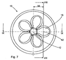
まず、図面の図1と図2とを参照すると、本発明のこの例の容器10は、ブロー成形PETの中空体である。前記容器10の本体は、円形水平断面を有し、その円の半径は容器10の閉じられたベース14の中央を貫通して延出する中央長手軸心12から直交方向に延出している。前記ベース14の上方には、図1及び図2には図示されていないが、ネック部が上に乗った実質的に円筒状の側壁が配設されている。前記側壁は、前記ベース14の下端部と一体であり、かつ、この下端部において終端し、これに対して、前記側壁は、容器10の上部において前記ネック部において上端部と一体であり、かつこの上端部において終端している。
Referring first to FIGS. 1 and 2 of the drawings, the
前記ベース14の基本又は基礎形状は、僅かに平坦化された半球状であり、この半球は容器10の中央軸心12周りで回転対称である。より一般的には、前記ベース14の基礎形状は、卵形回転楕円であり、それを交差する赤道円の面の直径よりも短いその原線(前記中央長手軸心12に一致する)上に直径を有する回転対称楕円である。この略半球形状によって内圧に対する抵抗が最大化され、亀裂に抗する応力集中が低減され、更に、材料使用量を最小限に留めながら内容積が最大化される。
The base or basic shape of the
本発明に拠れば、前記ベース14は、更に、このベース周りで花弁状に配設された一体成形されたブリスター状の脚部を有し、これら脚部はこの例においては、前記中央長手軸心12上において比較的浅いほぼ五角形の凸状部18から均等角度で放射状に延出する5つの中空卵形脚形成部16によって形成されている。より一般的には、前記脚形成部16は、長球(prolate spheroids)形状の長楕円であって、ここで、長球とはその原線に沿う直径がその赤道直径よりも大きな球である。
According to the present invention, the base 14 further comprises integrally molded blister-like legs arranged in a petal shape around the base, which in this example are the central longitudinal axis. It is formed by five hollow egg-shaped
前記回転楕円状脚形成部16の原線20は、容器10の前記中央長手軸心12から等角度で離間する径方向平面において外方上方に延出している。従って、前記脚形成部16(図2を参照)の原線20は、前記中央長手軸心12を取り囲む仮想切頭円錐表面上に位置する。
The
周方向に隣接する脚形成部16対は、前記五角形中央突出部18の頂点24から等角度で放射状に延出する谷部22によって互いに分離されている。これらの谷の床部は、ベース14の回転楕円形状に沿い、脚形成部16を超えて径方向外方に位置するベース14の外側部分へそれらの外側端部において開口している。更に、各脚形成部16と中央突出部18とは、明確な変わり目又は不連続性無くスムースに湾曲する遷移部分を介して互いに接続されている。従って、図3に図示されているように、脚形成部16と、スムースに湾曲する遷移部分と、そして央突出部18とで、湾曲断面が形成される。
The pair of
同様に図3に図示されているように、前記凸状中央突出部18は、前記回転楕円状ベース14の一般曲率半径Rよりも小さな曲率半径rを有する、即ちR>r。更に、前記凸状中央突出部18は、前記基礎ペース輪郭の最下方頂点を越えて、従って、使用時においてはそれよりも下方、のレベルまで延出している。又、前記凸状中央突出部18は、前記脚形成部16の延出範囲内、従って、使用時においてはその上方の、レベルにまで延出している。
Similarly, as shown in FIG. 3, the convex
前記脚形成部16は、卵形凸壁によってベース14の基礎回転楕円状輪郭から外側に膨出している。各脚形成部16の前記凸壁は、卵形リング形状の凹状遷移領域26によって包囲されている。前記遷移領域26は、大きな曲率半径で前記ベースの回転楕円状壁へとスムースに延出し、これによって応力集中を低減し、従って、応力亀裂を極小化する。周方向に隣接する脚形成部16の前記遷移領域26は、これら脚形成部16間の前記谷部22の一部を形成している。
The
各脚形成部16は、その下方平面図視において、全体として楕円状(この例では卵形)であり、その内側端部30とその外側端部32との間の拡大中央領域28において最大の幅に達している。従って、各脚形成部16は、前記中央領域28の最も幅広の部分から、内側部34に沿って内側に中央長手軸心12に向けて内側端部30へ、そして、外側部36に沿って前記中央長手軸心12から外側に外側端部32に向かって、これら反対方向にテーパーしている。
Each
下方平面図において、前記脚形成部16の内側にテーパーする内側部34は、オレンジの切片のように、円形ベース14周りで隣接するもの同士の間で密にフィットしている。脚形成部16のこれらの内側部分34は、この例においてはほぼ平行とすることが可能であるが、五角形中央突出部18から外側に延出するにしたがって幅がわずかに広がる谷部22の狭い内側部38と交互に受けられるとともに、それら内側部38によった互いに分離されている。しかしながら、それらが脚形成部16の最も幅広の部分を超えてそれらの外側部40へと外側に延出する場合、前記谷部22はそれが隣接する脚形成部16の外側端部32間で最大幅に達するまで、脚形成部16のテーパード外側部36間においてほぼ指数的に幅が広がる。
In the lower plan view, the
従って、中央長手軸心12から谷部22に沿ってベース14の外径に向かうにしたがって、脚形成部16間の隙間は増加する。これに対して、EP0671331に開示されているもののような従来知られている花弁状ベースにおいては、この隙間は減少する。
Accordingly, the gap between the
次に側方から見て、前記脚形成部16は、中央五角形突出部18によって形成されるベース14の最下方頂点を越えるレベルにまで、従って、使用時においてはそれの下方へと延出する。これら脚形成部16は全て、同じレベルにまで延出している。従って、そのレベルにおいて、各脚形成部16は、容器10の中央長手軸心12に対して直交する平坦な支持表面(図示せず)上に安定的に位置する接触点42を形成する。
Viewed next from the side, the
図3は、前記脚形成部がそれらの内側端部30に向けて僅かに内方かつ下方側にオフセットされた断面の最も幅広の部分を備える幾分卵形状であることを図示している。
FIG. 3 illustrates that the leg formers are somewhat oval shaped with the widest section in cross section offset slightly inward and downward toward their
前記脚形成部16の接触点42は、容器10の中央長手軸心12を中心とする接触円上でかつ、その周りで等間隔に配置されている。前記接触円の直径(x)は、以下の比率で、容器10の側壁の直径(Dy)に関係している。
Dy/0.5x=k
The contact points 42 of the
Dy / 0.5x = k
本発明に拠れば、kは好ましくは3.6〜5.5、より好ましくは、4.0〜5.3、更に好ましくは、4.2〜5.0であり、典型的には4.7である。これは、その対応の比率kが通常2.5〜3.5である市販されている典型的なPETボトルと対照的である。本発明におけるこの比較的大きなkの値は、xの値が比較的小さいことによるものである。これは、小さな接触円によって接触点42間において小さく、従って、本来的に硬質なダイアフラム(隔膜)が形成されるので有利である。 According to the present invention, k is preferably 3.6 to 5.5, more preferably 4.0 to 5.3, still more preferably 4.2 to 5.0, typically 4. 7. This is in contrast to a typical commercially available PET bottle whose corresponding ratio k is usually 2.5-3.5. This relatively large value of k in the present invention is due to the relatively small value of x. This is advantageous because it is small between the contact points 42 by a small contact circle and thus forms an inherently rigid diaphragm.
その結果、脚形成部16の接触点42間の接触円内の中央領域が極めて硬くて(リジッド)で、それゆえ、内圧から破裂圧まで移動に対する耐性を有するものとなる。接触円内の領域の剛性は、脚形成部16の内側部34、それらの間の谷部22と中央突出部18とによって形成される波状壁部によって高められる。
As a result, the central region in the contact circle between the contact points 42 of the
前記接触円内の剛性は、高い破裂圧のためのみならず、安定性のためにも重要である。これは、前記中央長手軸心上の最下点(中央五角形突出部18によって形成されるベース14の最下方頂点)が内圧で押し下げられる傾向があるからである。もしも前記最下点が使用時において支持面に接触するまで移動するならば、容器は、脚形成部16の接触点42上に安定的に静止することができなくなる。本発明のベース形状の剛性は、従来から知られている構成と比較して、ベースの中央頂点から支持面への距離が比較的短く、これが安定性と、容器の高さに対する容積とに有利になっているということを意味している。
The stiffness in the contact circle is important not only for high burst pressure but also for stability. This is because the lowest point on the central longitudinal axis (the lowest vertex of the base 14 formed by the central pentagonal protrusion 18) tends to be pushed down by internal pressure. If the lowest point moves until it comes into contact with the support surface in use, the container cannot rest stably on the
任意の脚形成部16を端部から(即ち、中央長手軸心12に向けて内側の容器10の側から)見た場合、その脚形成部16の輪郭は、各側への遷移領域26の凹部半径間において実質的に一定の凸半径を形成している。従来の花弁状ベースは、通常、脚部間においてV形状の谷を形成するより平坦な表面を有し、これが材料使用量と応力集中とに不利になっている。応力集中によって、高い内圧での破断に対して特に弱い容器の領域が形成される。
When an optional
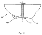
本発明のベース14の前記構成は、圧力下で液体を分与するための容器に特に適している。特に、kの値が大きいことによって、ベースの剛性が増し、従って、容器が高い内圧を受ける間に安定性を維持するのにより適したものとなっている。更に、kの値を大きくすることによって、そうでない場合に、高い内圧を受ける容器において可能であるよりも軸心方向においてより低い位置に凸状中央突出部18を設けることが可能となる。これによって容器10から実用的に分与可能な飲料の量を最大化することが可能となる。この利点について、図3の容器ベース14の同じ断面図が、飲料分与チューブ120と共に図示されている図12を参照して説明する。
The above configuration of the
このコンテクストにおいて、前記容器は、押し込み式にそのケグ10の筒状ネックに封止される閉じ構造を備えるビールケグ10として使用される。前記チューブ120は、前記閉じ構造(図示せず)に接続され、それから中央長手軸心12に沿ってケグ10のベース内へと延出している。チューブ120の軸心方向下方端部は、中央突出部18内へと延出している。このチューブ120の前記端部は、中央突出部18内に位置し、中央突出部18の頂点の内部に少し入ったところに架り、それによって、飲料がケグ10からチューブ120に、又はその反対方向に通過することが可能な環状空隙を提供している。前記中央突出部18の形状も、チューブ120の軸心方向下方端部が、取付け及び使用中において、中央突出部内に適切に位置し保持されることを可能にしている。
In this context, the container is used as a
使用時において、飲料を分与する時、ケグ10は直立位置に維持される。前記閉じ構造によって加圧ガスをケグ10のヘッドスペースに導入して、チューブ120を介して飲料を取り出すことを可能にする。チューブ120の軸心方向最下端部が中央突出部18内に位置し、この中央突出部18がケグ10内で比較的低い軸心方向位置にあるので、これによって、ケグ10内の飲料のほとんど全部をそれから確実に取り出すことが可能である。
In use, the
チューブ120を脚形成部16の一つの中に延出させることによって、ケグ10から実用的に取り出し可能な飲料の量を更に増大させることが可能であるかもしれない。そのような構成においては、チューブ120をその下端部において中央長手軸心12から離間するように曲げる必要があるであろう。これによってケグ10から分与可能な飲料の量を少し増加させることができるかもしれないが、それによって前記閉じ構造とチューブ120をケグ10に取付ける工程が複雑化する可能性がある。特に、曲がったチューブ120をケグ10に挿入するには、複雑な自動化取付け作業が必要となりうる。又、チューブ120を中央長手軸心12から離間するように曲げることによってこのチューブ120がその軸心方向上方端部に取付けられた前記閉じ構造に不均一な力がかかるかもしれない。そしてこれによって閉じアセンブリの信頼性が低下しうるが、これは、ケグ10が高い内圧を受ける場合には特に懸念がある。
By extending the
本発明の前記花弁状ベースは、広範囲の容器、例えば、ボトル及びケグ等に利用可能である。図4(a),4(b)及び4(c)そして図5(a),5(b)及び5(c)は、それぞれ、典型的には炭酸入りソフトドリンク用に使用することが可能な0.33リットル容量のボトル、典型的にはビール用に使用することが可能な20リットル容量のケグ46とに適用される本発明の5本脚ベースを図示している。これらの図面は、図1及び図2においては省略した特徴構成、即ち、ネック部50によって包囲された実質的に円筒状の側壁48、を図示している。この側壁48は、ベース14の下端部と一体であり、かつ、この下端部で終端している。そして、この側壁48は、容器の頂部において前記ネック部50の上端部と一体であり、かつ、この上端部で終端している。
The petal-like base of the present invention can be used for a wide range of containers, such as bottles and kegs. 4 (a), 4 (b) and 4 (c) and FIGS. 5 (a), 5 (b) and 5 (c), respectively, can typically be used for carbonated soft drinks. 1 illustrates a 5-leg base of the present invention applied to a 0.33 liter bottle, typically a 20
図10は、非円筒状側壁108を備える18リットル容量のケグ104に適用された本発明の別の5本脚ベースを図示している。この例において、前記側壁108は、ケグ104の中央長手軸心周りで回転対称な凸状であり、かつ、ほぼ卵の形状に沿っている。その軸心方向下端部において、前記側壁は、本発明の球状基礎ベース輪郭へとスムースに湾曲して延出している。前記軸心方向下端部よりもより大きくテーパしているその軸心方向上端部において、前記側壁は、ケグ104の凹状ネックへとスムースに湾曲している。前記凸側壁108をこのような形状することによって内圧耐性を最大化し、ケグ104の内容積を最大化し、更に、材料使用量を最小化している。図11は、図10に図示の容器へとブロー成形されるプラスチックプレフォームの拡大側面図である。
FIG. 10 illustrates another five leg base of the present invention applied to an 18
本発明の概念から逸脱することなく本発明のその他の変形例も可能である。例えば、図6(a),6(b)及び6(c)に図示の本発明のベースの変形例は、1.5リットルの容量のボトル52に適用されている。この変形例は、5個ではなく7個の脚形成部54を有し、それらの間にほぼ七角形の中央突出部56が形成されている。前記5本脚のベース変形例と同様、7本脚ベース変形例は、0.33リットル、0.5リットル、1リットル、1.5リットル、又はそれ以上のボトル、そして20リットル又はその他の容量のケグ等の任意のサイズの容器に適用可能である。
Other variations of the invention are possible without departing from the concept of the invention. For example, the modification of the base of the present invention shown in FIGS. 6 (a), 6 (b) and 6 (c) is applied to a
最適な安定性のためには奇数の脚部が好適であり、その場合、少なくとも3本の脚(その場合は中央突出部がほぼ三角形である)、7本以下の脚が好ましく、5本又は7本の脚が最適と見なされる。 An odd number of legs is preferred for optimum stability, in which case at least 3 legs (in which case the central protrusion is approximately triangular), 7 or fewer legs are preferred, 5 or Seven legs are considered optimal.
クレームに定義されているその最も広い範囲を限定することなく、本発明を意味づけるために、様々な寸法特徴構成を以下例示する。 Without limiting the broadest scope defined in the claims, various dimensional features are exemplified below to confer the present invention.
まず、下の表は、従来のベースと本発明のベースとの容量比較を示し、この場合、そのベースには5本の脚が形成されているものと仮定する。表中の容量は、ミリリットル(ml)単位で示されている。ここで容量とは、容器の筒状側壁の下方の容器部分として定義される、ベースの内容量のことをいう。本発明のベースは、従来の花弁状容器ベースの容量の約5倍の容量を有し、所与の容器容量に対するコンパクトさと材料使用量により有利なものである、ことが理解されるであろう。 First, the table below shows a capacity comparison between a conventional base and the base of the present invention, where it is assumed that the base has five legs. The volumes in the table are shown in milliliters (ml). Here, the capacity refers to the internal capacity of the base, which is defined as the container portion below the cylindrical side wall of the container. It will be appreciated that the base of the present invention has a capacity of about five times that of a conventional petal-like container base, and is more advantageous for compactness and material usage for a given container capacity. .

第2に、下記の寸法は、上の容器容量それぞれのベースの形状を定義するのに役立つ。 Second, the following dimensions help define the shape of the base for each of the above container volumes.
図7〜9は、5本脚ベース14を有する20リットルケグに関する追加の寸法情報を提供している。図10及び11は、それぞれ、5本脚ベースを有する18リットルケグ104とそのプレフォーム106とに関する寸法情報を提供している。
FIGS. 7-9 provide additional dimensional information for a 20 liter keg having a five
図8は、VIII−VIII線に沿う、図7の20リットルケグの花弁状ベースの一部側方断面図である。この断面は、脚形成部16をその接触点42で交差するとともに、ケグ10の中央長手軸心12に対して平行かつ、この軸心から50mmの距離径方向に離間している。前記脚形成部16のこの断面において、その輪郭は、各側への前記遷移領域26の12.0mmの凹半径間において実質的に一定の23.0mmの凸半径である。
8 is a partial cross-sectional side view of the petal-like base of the 20 liter keg of FIG. 7 along the line VIII-VIII. This cross section intersects the
図9は、IX−IX線に沿った、図7の20リットルケグの花弁状ベースの一部側方断面図である。その断面は、ケグ10の中央長手軸心12にアラインメントされ、かつ、図8に図示したものと同じ脚形成部16とその接触点42で交差している。図9の図は、図3の図に対応するが、20リットルケグに関する以下の追加寸法情報を提供する。
9 is a partial cross-sectional side view of the petal-like base of the 20 liter keg of FIG. 7 along the line IX-IX. The cross section is aligned with the central
これらの半径測定値は、容器10の他の脚形成部16上の点にも適用可能である。これらの点は、通常、容器の中央長手軸心12と所与の脚形成部16の原線との両方にアラインメントされる任意の平面中に位置する。
These radius measurements are also applicable to points on the other
距離データに加えて、以下のデータは、本発明による5本脚花弁状ベース14を備える20リットルケグ10の典型的なバースト圧を示す圧力テストから得られたものである。比較として、同様の条件下で従来の花弁状ベースにも圧力テストを行った。これら値は、バール単位でのバースト圧を表している。
In addition to the distance data, the following data was obtained from a pressure test showing a typical burst pressure of a 20
このように、5本脚ベースを備える前記20リットルケグの平均バースト圧は、約8.8バール=800kPaであることが判る。更に、前記20リットルケグの材料使用量は、0.234kgのPETに対応する。従って、圧力抵抗、容量及び材料使用に対する比率をこの20リットルケグに関して導くことができる。 Thus, it can be seen that the average burst pressure of the 20 liter keg with the 5 leg base is about 8.8 bar = 800 kPa. Furthermore, the material usage of the 20 liter keg corresponds to 0.234 kg of PET. Thus, ratios for pressure resistance, capacity and material usage can be derived for this 20 liter keg.
材料使用量に対する平均圧力抵抗の比率=3.76MPa/kg
材料使用量に対する容積の比率=85リットル/kg
Ratio of average pressure resistance to amount of material used = 3.76 MPa / kg
Volume ratio to material usage = 85 liters / kg
形状とサイズは異なるが、同様に本発明によるベース14を備える容器についても類似の比率を導くことができる。 Although the shape and size are different, a similar ratio can be derived for a container with a base 14 according to the invention as well.
図10は、18リットルのケグ104に対応する追加の寸法データを提供している。
FIG. 10 provides additional dimensional data corresponding to an 18
図11は、図10の18リットルケグ104のプレフォーム106に対応する追加の寸法データを提供している。
FIG. 11 provides additional dimensional data corresponding to the
5本脚ベースを備えるこの18リットルケグの凡そのバースト圧は、約14バール=1400kPaである。前記18リットルケグの材料使用量は、0.468kgのPETに対応する。従って、圧力抵抗、容量及び材料使用量に対する比率をこの18リットルケグに関して導くことができる。 The approximate burst pressure of this 18 liter keg with a 5 leg base is about 14 bar = 1400 kPa. The material usage of the 18 liter keg corresponds to 0.468 kg of PET. Thus, ratios to pressure resistance, capacity and material usage can be derived for this 18 liter keg.
材料使用量に対する平均圧力抵抗の比率=〜3MPa/kg
材料使用量に対する容積の比率=41リットル/kg
Ratio of average pressure resistance to amount of material used = ˜3 MPa / kg
Volume ratio to material usage = 41 liters / kg
5本脚ベースの場合、以下の比率がこれらの例において当てはまる。
20リットルケグの場合、
原線に沿った脚形成部の長さ/原線を横切る脚形成部の幅=1.35
接触円の直径/原線を横切る脚形成部の幅=1.68
基礎ベース輪郭の半径/側壁の直径=0.57
基礎ベース輪郭の半径/基礎ベース輪郭から側壁への遷移部の半径=2.72
基礎ベース輪郭の半径を超える脚形成部の径方向突出/基礎ベース輪郭の半径=1.13
For a five leg base, the following ratios apply in these examples:
For a 20 liter keg,
Length of leg forming part along the original line / width of leg forming part across the original line = 1.35
Diameter of contact circle / width of leg forming part across original line = 1.68
Base base contour radius / side wall diameter = 0.57
Radius of base base contour / radius of transition from base base contour to side wall = 2.72
Radial protrusion of leg forming part exceeding radius of base base contour / radius of base base contour = 1.13
様々な容積のボトルの場合、
原線に沿った脚形成部の長さ/原線を横切る脚形成部の幅=1.47
接触円の直径/原線を横切る脚形成部の幅=1.83
基礎ベース輪郭の半径/側壁の直径=0.58
基礎ベース輪郭の半径/基礎ベース輪郭から側壁への遷移部の半径=1.81
基礎ベース輪郭の半径を超える脚形成部の径方向突出/基礎ベース輪郭の半径=1.15
For bottles of various volumes,
Length of leg forming part along the original line / width of leg forming part across the original line = 1.47
Diameter of contact circle / width of leg forming portion across the original line = 1.83
Base base contour radius / side wall diameter = 0.58
Radius of base base contour / radius of transition from base base contour to side wall = 1.81
Radial protrusion of leg forming part exceeding radius of base base contour / radius of base base contour = 1.15
同様に、7本脚のベースの場合、以下の比率がこれらの例において当てはまる。
20リットルのケグの場合、
原線に沿った脚形成部の長さ/原線を横切る脚形成部の幅=1.44
接触円の直径/原線を横切る脚形成部の幅=1.82
基礎ベース輪郭の半径/側壁の直径=0.57
基礎ベース輪郭の半径/基礎ベース輪郭から側壁への遷移部の半径=2.72
基礎ベース輪郭の半径を超える脚形成部の径方向突出/基礎ベース輪郭の半径=1.13
Similarly, for a seven leg base, the following ratios apply in these examples:
For a 20 liter keg,
Length of leg forming part along the original line / width of leg forming part across the original line = 1.44
Diameter of contact circle / width of leg forming section across the original line = 1.82
Base base contour radius / side wall diameter = 0.57
Radius of base base contour / radius of transition from base base contour to side wall = 2.72
Radial protrusion of leg forming part exceeding radius of base base contour / radius of base base contour = 1.13
様々な容積のボトルの場合、
原線に沿った脚形成部の長さ/原線を横切る脚形成部の幅=1.59
接触円の直径/原線を横切る脚形成部の幅=2.03
基礎ベース輪郭の半径/側壁の直径=0.57
基礎ベース輪郭の半径/基礎ベース輪郭から側壁への遷移部の半径=1.8
基礎ベース輪郭の半径を超える脚形成部の径方向突出/基礎ベース輪郭の半径=1.15
For bottles of various volumes,
Length of leg forming part along the original line / width of leg forming part across the original line = 1.59
Diameter of contact circle / width of leg forming part across original line = 2.03
Base base contour radius / side wall diameter = 0.57
Radius of base base contour / radius of transition from base base contour to side wall = 1.8
Radial protrusion of leg forming part exceeding radius of base base contour / radius of base base contour = 1.15
以上の説明から、本発明の改良された花弁式ベース形状は様々な追加の利点を有するものであることが明白であろう。その、鋭利な半径が無く緩やかにカーブした形状は、応力亀裂に抗するのに有利である。又、重要なこととして、その表面積は同等の従来の公知の構成よりも小さい。従って、所与の量の樹脂に対して、本発明に拠れば、より厚みの大きな壁が可能となり、従って、より強度の高いベースが可能となる。或いは、ベースの強度を維持しながら、重量と材料使用量を低減することが可能である。炭酸入りソフトドリンク、ビール、高熱充填又は低温殺菌液体等のように、容器が高い内圧および/又は高い温度、に晒される用途においては頑丈なベースは特に重要である。 From the foregoing description, it will be apparent that the improved petal base shape of the present invention has various additional advantages. Its gently curved shape without sharp radii is advantageous to resist stress cracking. Significantly, the surface area is smaller than comparable conventional known configurations. Thus, for a given amount of resin, the present invention allows for a thicker wall and thus a stronger base. Alternatively, the weight and material usage can be reduced while maintaining the strength of the base. A rugged base is particularly important in applications where containers are exposed to high internal pressures and / or high temperatures, such as carbonated soft drinks, beer, high heat filling or pasteurized liquids.
Claims (29)
前記各脚形成部は、前記基礎ベース輪郭にスムースに延出する凹状断面の楕円状共通部分を有し、
前記脚形成部は、中央突出部から放射状に延出しており、
前記中央突出部は、前記基礎ベース輪郭の最下方頂点を越えたレベルにまで延出し、且つ前記基礎ベース輪郭の曲率半径よりも小さな曲率半径を有し、
前記脚形成部と前記中央突出部とは、スムースに湾曲する遷移部分を介して互いに接続されており、
前記遷移部分の湾曲が前記脚形成部と前記中央突出部との湾曲の逆であり、
前記脚形成部、前記スムースに湾曲する遷移部分、及び前記中央突出部は、協働で、湾曲する断面を形成しており、
波状壁部が、前記脚形成部の内側部、前記脚形成部の間の谷部、及び前記中央突出部によって形成されるベース。 A petal-like base for a self-supporting container, comprising a spherical base base contour and a plurality of spheroidal leg formations that interrupt the base base contour and project from the contour to form corresponding legs have a part and,
Each of the leg forming portions has an oval common portion with a concave cross section that smoothly extends to the base base contour,
The leg forming portion extends radially from the central protrusion,
The central protrusion extends to a level beyond the lowest vertex of the base base contour and has a radius of curvature smaller than the radius of curvature of the base base contour;
The leg forming portion and the central projecting portion are connected to each other via a smoothly curved transition portion,
The curve of the transition portion is the reverse of the curve of the leg forming portion and the central protrusion,
The leg forming part, the transition part that smoothly curves, and the central projecting part cooperate to form a curved section,
A base in which a wavy wall portion is formed by an inner portion of the leg forming portion, a valley portion between the leg forming portions, and the central projecting portion .
Applications Claiming Priority (3)
| Application Number | Priority Date | Filing Date | Title |
|---|---|---|---|
| GB1005717A GB2479360A (en) | 2010-04-06 | 2010-04-06 | Petaloid Container Base with Reduced Diameter Contact Circle |
| GB1005717.2 | 2010-04-06 | ||
| PCT/EP2011/055383 WO2011124626A2 (en) | 2010-04-06 | 2011-04-06 | Self-standing container |
Publications (3)
| Publication Number | Publication Date |
|---|---|
| JP2013523549A JP2013523549A (en) | 2013-06-17 |
| JP2013523549A5 JP2013523549A5 (en) | 2014-05-15 |
| JP5641267B2 true JP5641267B2 (en) | 2014-12-17 |
Family
ID=42228918
Family Applications (1)
| Application Number | Title | Priority Date | Filing Date |
|---|---|---|---|
| JP2013503105A Expired - Fee Related JP5641267B2 (en) | 2010-04-06 | 2011-04-06 | Self-supporting container |
Country Status (16)
| Country | Link |
|---|---|
| US (1) | US20130062306A1 (en) |
| EP (1) | EP2555984B1 (en) |
| JP (1) | JP5641267B2 (en) |
| CN (1) | CN103003161B (en) |
| AU (1) | AU2011237887B2 (en) |
| BR (1) | BR112012025471A2 (en) |
| DK (1) | DK2555984T3 (en) |
| ES (1) | ES2602135T3 (en) |
| GB (2) | GB2479360A (en) |
| HU (1) | HUE033351T2 (en) |
| PL (1) | PL2555984T3 (en) |
| PT (1) | PT2555984T (en) |
| RU (1) | RU2598995C9 (en) |
| UA (1) | UA109276C2 (en) |
| WO (1) | WO2011124626A2 (en) |
| ZA (1) | ZA201208013B (en) |
Families Citing this family (7)
| Publication number | Priority date | Publication date | Assignee | Title |
|---|---|---|---|---|
| FR3005035B1 (en) * | 2013-04-24 | 2016-01-15 | Sidel Participations | CONTAINER PROVIDED WITH A DOUBLE ARCHE DEFORMABLE BOTTOM |
| FR3007392B1 (en) * | 2013-06-25 | 2016-02-05 | Sidel Participations | RECIPIENT MINI PETALOIDE GROOVE |
| US10710765B2 (en) * | 2013-07-23 | 2020-07-14 | Graham Packaging Company, L.P. | Base for hot-fill plastic containers |
| GB201401457D0 (en) * | 2014-01-28 | 2014-03-12 | Petainer Large Container Ip Ltd | Improved self-standing container |
| TWD167046S (en) * | 2014-06-30 | 2015-04-11 | 深圳市景田食品飲料有限公 | Beverage bottle (136) |
| WO2016019361A1 (en) | 2014-08-01 | 2016-02-04 | The Coca-Cola Company | Small carbonated beverage packaging with enhanced shelf life properties |
| EP3233645A4 (en) * | 2014-12-19 | 2018-09-26 | The Coca-Cola Company | Carbonated beverage bottle bases and methods of making the same |
Family Cites Families (39)
| Publication number | Priority date | Publication date | Assignee | Title |
|---|---|---|---|---|
| US2391582A (en) * | 1944-05-02 | 1945-12-25 | Ralph Walsh | Spray control valve |
| GB840634A (en) * | 1957-05-15 | 1960-07-06 | Baguley S Sons 1932 Ltd J | Improvements in or relating to hot water cylinders |
| US3038627A (en) * | 1960-05-31 | 1962-06-12 | Specialties Dev Corp | High-pressure container safety means |
| FR1493309A (en) * | 1966-09-20 | 1967-08-25 | Frohn Plastic Gmbh Kunststoffw | Bottle-shaped container |
| US3870181A (en) * | 1973-02-12 | 1975-03-11 | Monsanto Co | Molecularly oriented bottle |
| USD254957S (en) * | 1977-08-17 | 1980-05-13 | Ball Corporation | Beverage container |
| USD257463S (en) * | 1977-08-17 | 1980-10-28 | Ball Corporation | Beverage container |
| JPS5821373Y2 (en) * | 1979-01-10 | 1983-05-06 | 株式会社吉野工業所 | Biaxially stretched synthetic resin thin wall bottle |
| JPS5821374Y2 (en) * | 1979-01-10 | 1983-05-06 | 株式会社吉野工業所 | Biaxially stretched synthetic resin thin wall bottle |
| JPS55110415U (en) * | 1979-01-26 | 1980-08-02 | ||
| US4313545A (en) * | 1979-02-13 | 1982-02-02 | The Nippon Aluminum Mfg. Co., Ltd. | Metallic pressure vessel with thin wall |
| NL8006687A (en) * | 1979-12-13 | 1981-07-16 | Shigeto Aoki | SOIL CONSTRUCTION FOR PLASTIC HOLDERS. |
| USD267233S (en) * | 1980-04-18 | 1982-12-14 | Katashi Aoki | Bottle |
| US4318489A (en) * | 1980-07-31 | 1982-03-09 | Pepsico, Inc. | Plastic bottle |
| USD269761S (en) * | 1980-08-12 | 1983-07-19 | Plastona (John Waddington) Limited | Can or the like |
| USD270332S (en) * | 1980-08-28 | 1983-08-30 | Plastona (John Waddington) Limited | Can or the like |
| US4368825A (en) * | 1980-11-28 | 1983-01-18 | Standard Oil Company (Indiana) | Self-standing bottle structure |
| AU90611S (en) * | 1982-12-29 | 1985-07-18 | Suntory Kabushiki Kaisha Suntory Ltd | A bottle |
| JPS59178214U (en) * | 1983-05-18 | 1984-11-28 | 三菱樹脂株式会社 | Synthetic resin thin wall bottle |
| WO1987004974A1 (en) * | 1986-02-14 | 1987-08-27 | Norderney Investments Limited | Improvements in or relating to plastics containers |
| US5205434A (en) * | 1992-06-09 | 1993-04-27 | Constar Plastics, Inc. | Footed container |
| US5454481A (en) * | 1994-06-29 | 1995-10-03 | Pan Asian Plastics Corporation | Integrally blow molded container having radial base reinforcement structure |
| JP3612775B2 (en) * | 1995-03-28 | 2005-01-19 | 東洋製罐株式会社 | Heat-resistant pressure-resistant self-supporting container and manufacturing method thereof |
| JP3676426B2 (en) * | 1995-05-25 | 2005-07-27 | 北海製罐株式会社 | Polyethylene terephthalate resin bottle |
| AU733235B2 (en) * | 1996-12-20 | 2001-05-10 | Ball Corporation | Plastic container for carbonated beverages |
| US6296471B1 (en) * | 1998-08-26 | 2001-10-02 | Crown Cork & Seal Technologies Corporation | Mold used to form a footed container and base therefor |
| US6112924A (en) * | 1998-09-10 | 2000-09-05 | Bcb Usa, Inc. | Container with base having cylindrical legs with circular feet |
| US6085924A (en) * | 1998-09-22 | 2000-07-11 | Ball Corporation | Plastic container for carbonated beverages |
| CN1611421A (en) * | 2003-10-27 | 2005-05-04 | 巫有发 | Improved container |
| ES2289226T3 (en) * | 2003-10-31 | 2008-02-01 | NESTLE WATERS MANAGEMENT & TECHNOLOGY | PRODUCT CONTAINER MANUFACTURED WITH LESS MATERIAL. |
| JP2006000408A (en) * | 2004-06-17 | 2006-01-05 | Samii Kk | Pinball machine |
| WO2006000408A1 (en) * | 2004-06-23 | 2006-01-05 | NESTLE WATERS MANAGEMENT & TECHNOLOGY (Société Anonyme) | A container for liquid with a lightweight bottom |
| US20060118560A1 (en) * | 2004-12-03 | 2006-06-08 | Schur Warren M | Water shedding designs for receptacle bottoms |
| JP4986105B2 (en) * | 2005-09-21 | 2012-07-25 | 株式会社吉野工業所 | Heat-resistant and pressure-resistant plastic bottle made of polyester resin |
| USD532307S1 (en) * | 2005-10-11 | 2006-11-21 | Nestle Waters Management And Technology | Bottle |
| CZ2006528A3 (en) * | 2006-08-25 | 2008-03-05 | Mušálek@Oto | Plastic-made foldable bottle |
| US20100072167A1 (en) * | 2008-09-25 | 2010-03-25 | Dickie Robert G | Collapsible bottle |
| US20120132676A1 (en) * | 2010-11-30 | 2012-05-31 | Reginal Rhodes | Liquid dispenser |
| USD701763S1 (en) * | 2011-05-20 | 2014-04-01 | Petainer Lidköping AB | Container attachment and container |
-
2010
- 2010-04-06 GB GB1005717A patent/GB2479360A/en not_active Withdrawn
-
2011
- 2011-04-06 CN CN201180027895.2A patent/CN103003161B/en not_active Expired - Fee Related
- 2011-04-06 ES ES11717204.9T patent/ES2602135T3/en active Active
- 2011-04-06 AU AU2011237887A patent/AU2011237887B2/en not_active Ceased
- 2011-04-06 RU RU2012147015/12A patent/RU2598995C9/en not_active IP Right Cessation
- 2011-04-06 PT PT117172049T patent/PT2555984T/en unknown
- 2011-04-06 DK DK11717204.9T patent/DK2555984T3/en active
- 2011-04-06 PL PL11717204T patent/PL2555984T3/en unknown
- 2011-04-06 EP EP11717204.9A patent/EP2555984B1/en not_active Not-in-force
- 2011-04-06 JP JP2013503105A patent/JP5641267B2/en not_active Expired - Fee Related
- 2011-04-06 HU HUE11717204A patent/HUE033351T2/en unknown
- 2011-04-06 BR BR112012025471A patent/BR112012025471A2/en not_active IP Right Cessation
- 2011-04-06 GB GB1105839.3A patent/GB2479451B/en not_active Expired - Fee Related
- 2011-04-06 WO PCT/EP2011/055383 patent/WO2011124626A2/en active Application Filing
- 2011-06-04 UA UAA201212641A patent/UA109276C2/en unknown
-
2012
- 2012-10-05 US US13/639,853 patent/US20130062306A1/en not_active Abandoned
- 2012-10-24 ZA ZA2012/08013A patent/ZA201208013B/en unknown
Also Published As
| Publication number | Publication date |
|---|---|
| CN103003161B (en) | 2016-03-30 |
| RU2012147015A (en) | 2014-05-20 |
| CN103003161A (en) | 2013-03-27 |
| AU2011237887A1 (en) | 2012-11-15 |
| GB201105839D0 (en) | 2011-05-18 |
| UA109276C2 (en) | 2015-08-10 |
| HUE033351T2 (en) | 2017-11-28 |
| EP2555984A2 (en) | 2013-02-13 |
| RU2598995C2 (en) | 2016-10-10 |
| RU2598995C9 (en) | 2016-11-20 |
| US20130062306A1 (en) | 2013-03-14 |
| BR112012025471A2 (en) | 2023-12-05 |
| AU2011237887B2 (en) | 2016-01-28 |
| WO2011124626A2 (en) | 2011-10-13 |
| WO2011124626A3 (en) | 2011-12-01 |
| EP2555984B1 (en) | 2016-08-24 |
| ZA201208013B (en) | 2014-03-26 |
| PL2555984T3 (en) | 2017-02-28 |
| GB2479360A (en) | 2011-10-12 |
| GB2479451A (en) | 2011-10-12 |
| DK2555984T3 (en) | 2016-12-05 |
| GB2479451B (en) | 2012-12-26 |
| GB201005717D0 (en) | 2010-05-19 |
| ES2602135T3 (en) | 2017-02-17 |
| JP2013523549A (en) | 2013-06-17 |
| PT2555984T (en) | 2016-11-16 |
Similar Documents
| Publication | Publication Date | Title |
|---|---|---|
| JP5641267B2 (en) | Self-supporting container | |
| US4247012A (en) | Bottom structure for plastic container for pressurized fluids | |
| RU2522059C2 (en) | Bottle neck with inner bulges and method of its manufacture | |
| US6213325B1 (en) | Footed container and base therefor | |
| US4249667A (en) | Plastic container with a generally hemispherical bottom wall having hollow legs projecting therefrom | |
| US10246210B2 (en) | Container having a petaloid base and groove | |
| US7686178B2 (en) | Flask | |
| CN105050903B (en) | Container with double-arc deformable bottom | |
| US20160288946A1 (en) | Container having a bottom provided with a stepped arch | |
| US20160340072A1 (en) | Self-standing container | |
| JP6801272B2 (en) | Synthetic resin container | |
| CN110740941B (en) | Container bottom base with double concave arch | |
| EP3154864B1 (en) | Reinforced base for plastic bottles or flasks | |
| JP7400380B2 (en) | Synthetic resin container | |
| JP7455081B2 (en) | plastic bottle | |
| JP5256155B2 (en) | Can body body with bottomed cylindrical body and beverage can product filled with beverage | |
| JP2021095182A (en) | Synthetic resin container | |
| JP2016222254A (en) | Self-standing pressure-resistant bottle | |
| JP2023067216A (en) | Synthetic resin container | |
| JP2020055592A (en) | Synthetic resin container |
Legal Events
| Date | Code | Title | Description |
|---|---|---|---|
| A521 | Request for written amendment filed |
Free format text: JAPANESE INTERMEDIATE CODE: A523 Effective date: 20140328 |
|
| A621 | Written request for application examination |
Free format text: JAPANESE INTERMEDIATE CODE: A621 Effective date: 20140328 |
|
| A871 | Explanation of circumstances concerning accelerated examination |
Free format text: JAPANESE INTERMEDIATE CODE: A871 Effective date: 20140328 |
|
| A975 | Report on accelerated examination |
Free format text: JAPANESE INTERMEDIATE CODE: A971005 Effective date: 20140425 |
|
| A131 | Notification of reasons for refusal |
Free format text: JAPANESE INTERMEDIATE CODE: A131 Effective date: 20140605 |
|
| TRDD | Decision of grant or rejection written | ||
| A01 | Written decision to grant a patent or to grant a registration (utility model) |
Free format text: JAPANESE INTERMEDIATE CODE: A01 Effective date: 20141002 |
|
| A61 | First payment of annual fees (during grant procedure) |
Free format text: JAPANESE INTERMEDIATE CODE: A61 Effective date: 20141014 |
|
| R150 | Certificate of patent or registration of utility model |
Ref document number: 5641267 Country of ref document: JP Free format text: JAPANESE INTERMEDIATE CODE: R150 |
|
| R250 | Receipt of annual fees |
Free format text: JAPANESE INTERMEDIATE CODE: R250 |
|
| LAPS | Cancellation because of no payment of annual fees |