JP5639504B2 - Game machine - Google Patents

Game machine Download PDF

Info

Publication number
JP5639504B2
JP5639504B2 JP2011043249A JP2011043249A JP5639504B2 JP 5639504 B2 JP5639504 B2 JP 5639504B2 JP 2011043249 A JP2011043249 A JP 2011043249A JP 2011043249 A JP2011043249 A JP 2011043249A JP 5639504 B2 JP5639504 B2 JP 5639504B2
Authority
JP
Japan
Prior art keywords
support means
frame
cylindrical support
cylindrical
sound
Prior art date
Legal status (The legal status is an assumption and is not a legal conclusion. Google has not performed a legal analysis and makes no representation as to the accuracy of the status listed.)
Active
Application number
JP2011043249A
Other languages
Japanese (ja)
Other versions
JP2012179156A (en
Inventor
龍平 齊藤
龍平 齊藤
Current Assignee (The listed assignees may be inaccurate. Google has not performed a legal analysis and makes no representation or warranty as to the accuracy of the list.)
Newgin Co Ltd
Original Assignee
Newgin Co Ltd
Priority date (The priority date is an assumption and is not a legal conclusion. Google has not performed a legal analysis and makes no representation as to the accuracy of the date listed.)
Filing date
Publication date
Application filed by Newgin Co Ltd filed Critical Newgin Co Ltd
Priority to JP2011043249A priority Critical patent/JP5639504B2/en
Publication of JP2012179156A publication Critical patent/JP2012179156A/en
Application granted granted Critical
Publication of JP5639504B2 publication Critical patent/JP5639504B2/en
Active legal-status Critical Current
Anticipated expiration legal-status Critical

Links

Images

Landscapes

  • Pinball Game Machines (AREA)

Description

この発明は、打球発射用のハンドルユニットを備えた遊技機に関するものである。   The present invention relates to a gaming machine provided with a handle unit for hitting a ball.

代表的な遊技機であるパチンコ機は、前後に開口する矩形枠状に形成されて遊技店の設置枠台に固定される固定枠としての外枠と、該外枠に対して開閉可能に支持されて遊技盤を着脱可能に保持する本体枠としての中枠と、該中枠の前側に開閉可能に支持されてパチンコ機前面を装飾すると共に遊技盤を透視保護する装飾枠としての前枠とを基本的に備えている。またパチンコ機では、中枠に配設された打球発射装置を作動するためのハンドルユニットが、中枠の正面右下部において前方に突出するよう設けられている。そして、遊技者がハンドルユニットを回動操作し、その操作量に応じた発射力によって打球発射装置からパチンコ球が遊技領域に打ち出されて所要の遊技が行なわれる(例えば、特許文献1参照)。   A pachinko machine, which is a typical gaming machine, is formed in a rectangular frame shape that opens to the front and back, and is supported by an outer frame as a fixed frame that is fixed to an installation frame base of a game store, so that the outer frame can be opened and closed. A middle frame as a main body frame that holds the game board in a detachable manner, and a front frame as a decoration frame that is supported on the front side of the middle frame so as to be openable and closable, decorates the front of the pachinko machine, and protects the game board from perspective Is basically equipped. Further, in the pachinko machine, a handle unit for operating the hitting ball launching device disposed in the middle frame is provided so as to protrude forward in the lower right front portion of the middle frame. Then, the player rotates the handle unit, and a pachinko ball is launched from the hitting ball launching device into the game area by a launching force corresponding to the operation amount (see, for example, Patent Document 1).

特開2009−273656号公報JP 2009-273656 A

前記パチンコ機では、トラブル発生時や電源をOFFする場合等において中枠を開放する際には、外枠に対する中枠の施錠を解除した状態で、前記ハンドルユニットを掴んで手前に引くことで該中枠を開放している。また、外枠に対して中枠を閉鎖する際には、ハンドルユニットを掴んだ状態で、該中枠を外枠に対して施錠位置まで押し込んでいる。   In the pachinko machine, when the middle frame is opened in the event of trouble or when the power is turned off, the handle unit is unlocked and the handle unit is grasped and pulled forward. The middle frame is open. Further, when closing the middle frame with respect to the outer frame, the middle frame is pushed into the locking position with respect to the outer frame with the handle unit being held.

前記中枠は、パチンコ機を構成する大多数の遊技構成部品が配設された重量のある部材であり、このように重量のある中枠を開閉する際にハンドルユニットを掴んで引いたり押したりする操作に際しては、該ハンドルユニットの中枠に対する取付け部分に大きな負荷が加わり、該取付け部分が変形したり破損等を生ずるおそれがある。そして、前記取付け部分が変形したり破損等した場合は、ハンドルユニットのスムーズな操作ができなくなったり、該ユニットを適正な位置や姿勢に保持できなくなる等の問題を招くことから、ハンドルユニットを取付ける部分の強度向上が求められている。
すなわち本発明は、従来の技術に係る遊技機に内在する前記問題に鑑み、これらを好適に解決するべく提案されたものであって、ハンドルユニットを取付ける部分の変形や破損等を防止し得る遊技機を提供することを目的とする。
The middle frame is a heavy member on which a large number of game components constituting the pachinko machine are arranged. Thus, when opening and closing the heavy middle frame, the handle unit is grasped and pulled or pushed. During the operation, a large load is applied to the mounting portion of the handle unit with respect to the inner frame, and the mounting portion may be deformed or damaged. If the mounting part is deformed or damaged, the handle unit may not be operated smoothly or the unit may not be held in an appropriate position or posture. There is a need to improve the strength of the part.
That is, the present invention has been proposed in order to suitably solve these problems inherent in the gaming machine according to the prior art, and a game capable of preventing deformation or breakage of a portion to which the handle unit is attached. The purpose is to provide a machine.

前記課題を克服し、所期の目的を達成するため、本願の請求項1に係る発明は、
遊技盤(12)が配設される本体枠(13)が固定枠(11)に対して開閉自在に支持され、前記本体枠(13)の前側に打球発射用のハンドルユニット(20)が配設された遊技機において、
前記本体枠(13)から前方に向けて筒状に延出し、前記ハンドルユニット(20)を挿通状態で支持する筒状支持手段(59)と、
前記本体枠(13)に設けられて前記筒状支持手段(59)を囲う被覆部材(66)と、
前記被覆部材(66)の前後に貫通し、前記筒状支持手段(59)が挿通される挿通孔(69a)と、
前記筒状支持手段(59)の外面および被覆部材(66)における挿通孔(69a)の内面との一方の面に突設されたリブ(65)および他方の面に形成されて該リブ(65)が嵌合する溝部(69b)とを備え、
前記リブ(65)と溝部(69b)とが嵌合した状態で前記筒状支持手段(59)の延出端部を、前記挿通孔(69a)の前端内面に当接した状態で被覆部材(66)により支持するよう構成され、
前記挿通孔(69a)は周方向において前後方向の長さが異なるように形成され、前記筒状支持手段(59)の延出端部における筒状支持手段(59)の外周面と、前記挿通孔(69a)の前端内面との当接長さが、該筒状支持手段(59)の周方向で異なるように構成したことを要旨とする。
請求項1に係る発明によれば、本体枠に対してハンドルユニットを取り付ける部分の剛性を高めて変形や破損等を防止し、ハンドルユニットの適正な配設状態を長期に亘って維持できる。
In order to overcome the above-mentioned problems and achieve the intended purpose, the invention according to claim 1 of the present application provides:
A main body frame (13) on which the game board (12) is disposed is supported to be openable and closable with respect to the fixed frame (11), and a handle unit (20) for launching a hit ball is arranged on the front side of the main body frame (13). In the installed gaming machine,
A cylindrical support means (59) extending in a cylindrical shape from the main body frame (13) forward and supporting the handle unit (20) in an inserted state,
A covering member (66) provided on the main body frame (13) and surrounding the cylindrical support means (59);
An insertion hole (69a) that passes through the front and rear of the covering member (66) and through which the cylindrical support means (59) is inserted;
A rib (65) projecting from one surface of the outer surface of the cylindrical support means (59) and the inner surface of the insertion hole (69a) in the covering member (66) and the rib (65 ) And a groove portion (69b) to be fitted,
With the rib (65) and the groove (69b) fitted , the extending end of the cylindrical support means (59) is in contact with the inner surface of the front end of the insertion hole (69a) ( It is so that configured to support a 66),
The insertion hole (69a) is formed to have different lengths in the front-rear direction in the circumferential direction, and the outer peripheral surface of the cylindrical support means (59) at the extending end of the cylindrical support means (59), and the insertion hole The gist is that the contact length of the hole (69a) with the inner surface of the front end is different in the circumferential direction of the cylindrical support means (59) .
According to the first aspect of the present invention, the rigidity of the portion where the handle unit is attached to the main body frame is increased to prevent deformation and breakage, and the proper arrangement state of the handle unit can be maintained over a long period of time.

請求項2に係る発明では、前記被覆部材(66)は、前記筒状支持手段(59)の軸方向に所定長さで延在して前記挿通孔(69a)が形成される筒受部(69)を備え、該筒受部(69)の延在方向に沿って前記リブ(65)および溝部(69b)が形成されることを要旨とする。
請求項2に係る発明によれば、リブと溝部とを筒状支持手段の軸方向に沿って延在するよう形成したので、被覆部材で支持される筒状支持手段の剛性を高め、ハンドルユニットの適正な配設状態をより長期に亘って維持できる。
In the invention according to claim 2, the covering member (66) extends in a predetermined length in the axial direction of the cylindrical support means (59) to form the insertion hole (69a). 69), and the rib (65) and the groove (69b) are formed along the extending direction of the tube receiving portion (69).
According to the invention of claim 2, since the rib and the groove are formed so as to extend along the axial direction of the cylindrical support means, the rigidity of the cylindrical support means supported by the covering member is increased, and the handle unit The proper arrangement state can be maintained for a longer period.

請求項3に係る発明では、前記リブ(65)および溝部(69b)は、前記筒状支持手段(59)の周方向に離間した位置に、該筒状支持手段(59)の軸方向へ延在するよう複数形成されることを要旨とする。
請求項3に係る発明によれば、リブおよび溝部を複数形成したので、筒状支持手段の剛性を更に向上することができる。
In the invention according to claim 3, the rib (65) and the groove (69b) extend in the axial direction of the cylindrical support means (59) at positions spaced apart in the circumferential direction of the cylindrical support means (59). The gist of the present invention is that a plurality are formed so as to exist.
According to the invention of claim 3, since the plurality of ribs and groove portions are formed, the rigidity of the cylindrical support means can be further improved.

請求項4に係る発明では、前記筒状支持手段(59)は、前記ハンドルユニット(20)を挿通状態で支持すると共に前記リブ(65)または溝部(69b)が形成された筒状部(62)と、該筒状部(62)における本体枠(13)側の端部に設けられて前記ハンドルユニット(20)の挿通方向と交差する外方へ延出する基部(63)とを備え、該筒状支持手段(59)は基部(63)が前記本体枠(13)に着脱自在に取付けられることを要旨とする。
請求項4に係る発明によれば、筒状部から外方へ延出する基部を介して筒状支持手段を本体枠に取付けるよう構成することで、該筒状支持手段の本体枠に対する取付け強度が向上する。
請求項5に係る発明では、前記筒状部(62)と基部(63)との接続部に、該筒状部(62)の外周面より外方に突出する補強部(64)が周方向に離間して複数形成されることを要旨とする。
請求項5に係る発明によれば、筒状支持手段の剛性が更に向上する。
In the invention according to claim 4, the cylindrical support means (59) supports the handle unit (20) in an inserted state and has a cylindrical portion (62) in which the rib (65) or the groove (69b) is formed. And a base portion (63) provided at an end of the cylindrical portion (62) on the main body frame (13) side and extending outwardly intersecting the insertion direction of the handle unit (20), The cylindrical support means (59) is characterized in that the base (63) is detachably attached to the main body frame (13).
According to the invention which concerns on Claim 4, it is comprised so that a cylindrical support means may be attached to a main body frame via the base part extended outward from a cylindrical part, The attachment strength with respect to a main body frame of this cylindrical support means Will improve.
In the invention which concerns on Claim 5, the reinforcement part (64) which protrudes outward from the outer peripheral surface of this cylindrical part (62) is the circumferential direction at the connection part of the said cylindrical part (62) and base (63) The gist is that a plurality are formed apart from each other.
According to the invention which concerns on Claim 5, the rigidity of a cylindrical support means further improves.

本発明に係る遊技機によれば、本体枠に対してハンドルユニットを取付ける部分の変形や破損等を防止して該ハンドルユニットの適正な配設状態を維持し得る。   According to the gaming machine according to the present invention, it is possible to prevent the portion where the handle unit is attached to the main body frame from being deformed or damaged, and to maintain the proper arrangement state of the handle unit.

本発明の好適な実施例に係るパチンコ機を示す正面図である。1 is a front view showing a pachinko machine according to a preferred embodiment of the present invention. 実施例に係るパチンコ機を、中枠に対して前枠および下球受け皿を開放した状態を示す斜視図である。It is a perspective view which shows the state which open | released the front frame and the lower ball saucer with respect to the middle frame about the pachinko machine concerning an Example. 実施例に係る中枠に対して下球受け皿を開放した状態でスピーカの設置部分を示す要部斜視図である。It is a principal part perspective view which shows the installation part of a speaker in the state which open | released the lower ball saucer with respect to the inner frame which concerns on an Example. 実施例に係るパチンコ機の横断平面図である。It is a cross-sectional top view of the pachinko machine concerning an example. (a)は実施例に係るパチンコ機の要部縦断側面図であって、(b)は(a)におけるA部の拡大図である。(a) is the principal part vertical side view of the pachinko machine based on an Example, (b) is an enlarged view of the A section in (a). 実施例に係るパチンコ機におけるスピーカの設置部分を示す要部横断平面図である。It is a principal part cross-sectional top view which shows the installation part of the speaker in the pachinko machine which concerns on an Example. 実施例に係る下球受け皿の要部背面図である。It is a principal part rear view of the lower sphere saucer concerning an example. 実施例に係るスピーカの出力部と音放出口と膨出部との関係を示す説明図であって、(a)は前側から視た図であり、(b)は左側から視た図であり、(c)は上側から視た図である。It is explanatory drawing which shows the relationship between the output part of the speaker which concerns on an Example, a sound emission opening, and a bulging part, Comprising: (a) is the figure seen from the front side, (b) is the figure seen from the left side. (C) is the figure seen from the upper side. 実施例に係るパチンコ機におけるハンドルユニットの設置部分を示す要部横断平面図である。It is a principal part cross-sectional top view which shows the installation part of the handle unit in the pachinko machine which concerns on an Example. 実施例に係るハンドルユニット、筒状支持手段およびハンドル飾りを分解して示す斜視図である。It is a perspective view which decomposes | disassembles and shows the handle | steering-wheel unit which concerns on an Example, a cylindrical support means, and a handle decoration. 実施例に係るハンドルユニット、筒状支持手段およびハンドル飾りを組付け状態で示す縦断正面図である。It is a vertical front view which shows the handle | steering-wheel unit which concerns on an Example, a cylindrical support means, and a handle decoration in the assembly | attachment state. 実施例に係るハンドル飾りの背面図である。It is a rear view of the handle decoration which concerns on an Example. (a)は実施例に係るパチンコ機の要部を示す右側面図であって、(b)は(a)におけるB部の拡大図である。(a) is a right view which shows the principal part of the pachinko machine based on an Example, (b) is an enlarged view of the B section in (a).

次に、本発明に係る遊技機につき、好適な実施例を挙げて、添付図面を参照しながら以下詳細に説明する。なお、実施例では、遊技球としてパチンコ球を用いて遊技を行なうパチンコ機を例に挙げて説明する。また、以下の説明において、「前」、「後」、「左」、「右」とは、特に断りのない限り、図1に示すようにパチンコ機を前側(遊技者側)から見た状態で指称する。   Next, the gaming machine according to the present invention will be described in detail below with reference to the accompanying drawings by way of preferred embodiments. In the embodiment, a pachinko machine that plays a game using a pachinko ball as a game ball will be described as an example. Further, in the following description, “front”, “rear”, “left”, and “right” are states when the pachinko machine is viewed from the front side (player side) as shown in FIG. 1 unless otherwise specified. It points at.

(パチンコ機について)
実施例に係るパチンコ機10は、図1または図2に示すように、前後に開口する矩形枠状に形成されて遊技店の設置枠台に固定される固定枠としての外枠11と、該外枠11に対して開閉および着脱が可能に支持されて遊技盤12を着脱可能に保持する本体枠としての中枠13と、該中枠13の前側に開閉および着脱が可能に支持されてパチンコ機前面を装飾すると共に遊技盤12を透視保護する装飾枠としての前枠14とを基本的に備える。
(About pachinko machines)
As shown in FIG. 1 or FIG. 2, the pachinko machine 10 according to the embodiment is formed in a rectangular frame shape that opens in front and rear, and an outer frame 11 as a fixed frame that is fixed to an installation frame base of a game store, A middle frame 13 as a main body frame that is supported so as to be able to be opened and closed and attached to and detached from the outer frame 11 so as to be detachable, and a pachinko that is supported on the front side of the middle frame 13 so that it can be opened and closed and detached. A front frame 14 is basically provided as a decorative frame that decorates the front of the machine and protects the game board 12 from perspective.

(外枠について)
前記外枠11は、図2に示すように、上縁を構成する上枠材11aと、下縁を構成する下枠材11bと、左縁を構成する左枠材11cと、右縁を構成する右枠材11dとを相互に連結固定することで矩形枠状に形成される。下枠材11bには、左枠材11cの前端面から右枠材11dの前端面まで延在する横長矩形状に形成されて後方へ開口する箱状に形成された意匠板(第1の部材)15が配設されている。意匠板15の前縁を構成する前壁15aの前面には、パチンコ機10のモチーフに応じた装飾が施されて当該パチンコ機10の装飾性を向上するようになっている。
(Outer frame)
As shown in FIG. 2, the outer frame 11 constitutes an upper frame member 11a constituting an upper edge, a lower frame member 11b constituting a lower edge, a left frame member 11c constituting a left edge, and a right edge. The right frame member 11d is connected and fixed to each other to form a rectangular frame shape. The lower frame member 11b is a design plate (first member) formed in a horizontally long rectangular shape extending from the front end surface of the left frame member 11c to the front end surface of the right frame member 11d and opening rearward. ) 15 is provided. The front surface of the front wall 15a constituting the front edge of the design board 15 is decorated according to the motif of the pachinko machine 10 to improve the decoration of the pachinko machine 10.

前記意匠板15の裏側に、左右の枠材11c,11d間に亘って延在するボックスカバー16が配設され、図5に示す如く、該ボックスカバー16と意匠板15との間に、外枠11の左右方向の略全長に亘って延在する空間S1を画成するよう構成される。ボックスカバー16には、空間S1に連通すると共に意匠板15の上縁を構成する上壁15bの上面から上方へ突出するダクト部16aが突設され、該ダクト部16aの前方に開口する接続口(図示せず)に、中枠13を外枠11に対して閉成した閉鎖状態で該中枠13に形成した後述のスピーカ収容室S2の接続口が接続し、ダクト部16aを介してスピーカ収容室S2と空間S1とが連通するよう構成される。また意匠板15における前壁15aには、ダクト部16aから右方に離間した位置に、前記空間S1に連通する下部放音口15cが前後に貫通するよう形成されている(図1および図2参照)。   A box cover 16 extending between the left and right frame members 11c and 11d is disposed on the back side of the design plate 15, and an outer space is provided between the box cover 16 and the design plate 15 as shown in FIG. The frame 11 is configured to define a space S1 extending over substantially the entire length in the left-right direction. The box cover 16 is provided with a duct portion 16a that communicates with the space S1 and protrudes upward from the upper surface of the upper wall 15b that constitutes the upper edge of the design plate 15, and is a connection port that opens to the front of the duct portion 16a. (Not shown) is connected to a connection port of a speaker housing chamber S2 (described later) formed in the inner frame 13 in a closed state in which the inner frame 13 is closed with respect to the outer frame 11, and the speaker is connected via the duct portion 16a. The storage room S2 and the space S1 are configured to communicate with each other. Further, a lower sound outlet 15c communicating with the space S1 is formed in the front wall 15a of the design plate 15 so as to penetrate in the front-rear direction at a position spaced to the right from the duct portion 16a (FIGS. 1 and 2). reference).

前記意匠板15における上壁15bの上面には、左右方向に離間して複数の傾斜案内部17が突設されている。各傾斜案内部17の上面には、図5に示す如く、後方へ向けて上方傾斜し、中枠13を閉成する過程で中枠13の下端部(具体的には下枠体13b)が接触する傾斜面部17aと、該傾斜面部17aの傾斜後端に連接して前後方向に水平に延在し、中枠13を完全に閉成した閉鎖状態とした際に、当該中枠13の下端部を支持する支持面部17bとを備えている。すなわち、中枠13を閉成する過程で該中枠13の下端部が傾斜面部17aに接触し、中枠13を更に閉成することで、中枠13の下端部が傾斜面部17aに沿って乗り上げて、最終的に支持面部17bで支持されるようになっている。そして、外枠11に対して中枠13の閉鎖状態では、中枠13の下面と意匠板15における上壁15bの上面とが上下に重なるように対向すると共に、該中枠13の下面が複数の傾斜案内部17の支持面部17bで支持される。   A plurality of inclined guide portions 17 project from the upper surface of the upper wall 15b of the design plate 15 so as to be separated in the left-right direction. As shown in FIG. 5, a lower end portion (specifically, a lower frame body 13 b) of the intermediate frame 13 is formed on the upper surface of each inclined guide portion 17 in the upward inclination toward the rear as the intermediate frame 13 is closed. The lower end of the intermediate frame 13 when the intermediate frame 13 is in a closed state, in contact with the inclined surface portion 17a and the inclined rear end of the inclined surface portion 17a and extending horizontally in the front-rear direction. And a support surface portion 17b for supporting the portion. That is, in the process of closing the middle frame 13, the lower end portion of the middle frame 13 comes into contact with the inclined surface portion 17 a, and the middle frame 13 is further closed so that the lower end portion of the inner frame 13 extends along the inclined surface portion 17 a. It rides and is finally supported by the support surface portion 17b. When the middle frame 13 is closed with respect to the outer frame 11, the lower surface of the middle frame 13 and the upper surface of the upper wall 15b of the design plate 15 face each other so as to overlap vertically, and a plurality of lower surfaces of the middle frame 13 are provided. Is supported by the support surface portion 17b of the inclined guide portion 17.

前記意匠板15の上壁15bにおける後端には、図5(a)に示す如く、上方に立上がった後に前方に突出する庇状部15dが、左右方向の略全長に亘って形成されている。該庇状部15dの高さ寸法は、前記傾斜案内部17における支持面部17bの高さより高く設定されており、外枠11に対する中枠13の閉鎖状態で、該中枠13の下部後面(下枠体13bの後面)が庇状部15dの前端に当接して、意匠板15の上方空間を左右方向の略全長に亘って上下方向で遮断するよう構成される。   At the rear end of the upper wall 15b of the design plate 15, as shown in FIG. 5 (a), a hook-shaped portion 15d that protrudes forward after rising upward is formed over substantially the entire length in the left-right direction. Yes. The height of the flange-shaped portion 15d is set to be higher than the height of the support surface portion 17b in the inclined guide portion 17, and when the middle frame 13 is closed with respect to the outer frame 11, the lower rear surface of the middle frame 13 (lower The rear surface of the frame 13b is in contact with the front end of the bowl-shaped portion 15d, and the upper space of the design plate 15 is blocked in the vertical direction over substantially the entire length in the horizontal direction.

(中枠について)
前記中枠13は、図2に示す如く、上側縁をなす上枠体13aと、下側縁をなし、スピーカ18、打球発射装置19および打球発射装置19を操作するためのハンドルユニット(ハンドル)20等の各種遊技部品を設置する設置部材として機能する合成樹脂製の下枠体13bと、左側縁をなす左枠体13cと、右側縁をなす右枠体13dとから略矩形状に形成されて、全体が前記外枠11における意匠板15より上方の開口前面に整合する矩形枠状サイズに形成される。そして外枠11に対して中枠13は、互いの正面左側上下に配設された第1ヒンジ機構21,21で横開き開閉および着脱が可能に取付けられ、正面右側に設けられた、パチンコ機10で一般的に使用されている「ダブル錠型式」の施錠装置22を利用して常には外枠11と係合された閉鎖状態に保持される。中枠13には、4つの枠体13a,13b,13c,13dにより前後に開口する遊技盤保持部23が画成され、左枠体13cに配設された上下の係合金具24,24と、上下の枠体13a,13bの右端部に設けたロック部材25,25とを利用して、遊技盤12が遊技盤保持部23に着脱可能にセット保持される。なお、中枠13は、上下・左右の枠体を一体で形成したものであってもよい。なお、図1,図2において、遊技盤12の前面に配設されている各種の遊技部品は、後述する案内レール26および盤面飾り部材27を除いて図示省略してある。
(About the middle frame)
As shown in FIG. 2, the middle frame 13 has an upper frame body 13 a that forms an upper edge and a lower edge, and a handle unit (handle) for operating the speaker 18, the ball hitting device 19, and the ball hitting device 19. It is formed in a substantially rectangular shape from a synthetic resin lower frame 13b that functions as an installation member for installing various game parts such as 20, a left frame 13c that forms a left edge, and a right frame 13d that forms a right edge. Thus, the entire frame is formed in a rectangular frame size that aligns with the front surface of the outer frame 11 above the design plate 15. The middle frame 13 is attached to the outer frame 11 so that the first hinge mechanisms 21 and 21 disposed on the upper left and right sides of the front side can be opened and closed laterally and attached to and detached from each other. 10 is always held in a closed state engaged with the outer frame 11 by using a “double lock type” locking device 22 generally used in the system 10. The middle frame 13 defines a game board holding portion 23 that is opened forward and backward by four frames 13a, 13b, 13c, and 13d, and upper and lower engagement fittings 24, 24 disposed on the left frame 13c. The game board 12 is detachably set and held on the game board holding part 23 by using the lock members 25 and 25 provided at the right ends of the upper and lower frame bodies 13a and 13b. In addition, the middle frame 13 may be formed by integrally forming upper, lower, left and right frame bodies. In FIG. 1 and FIG. 2, various game components arranged on the front surface of the game board 12 are omitted except for a guide rail 26 and a board decoration member 27 described later.

(遊技盤について)
前記遊技盤12は、合板等の木製板部材の表面にセル板を配設したもの、あるいはアクリル板等の透明な合成樹脂製等からなる平板状の板部材で構成される。遊技盤12の前面には、円弧状に形成した案内レール26と盤面飾り部材27とにより遊技領域12aが略円形状に画成され(図2参照)、前記中枠13に配設された打球発射装置19から発射されたパチンコ球が遊技領域12a内に打ち出され、該遊技領域12a内をパチンコ球が流下して遊技が行なわれる。また遊技盤12の前面には、図示しないが、遊技領域12a内に枠状装飾部材、パチンコ球が入賞可能な始動入賞装置、特別入賞装置、普通入賞装置等の各種入賞装置および多数本の遊技釘や風車等の各種遊技部品が配設されている。遊技盤12の裏側には、図柄表示装置28(図1参照)、可動演出装置および発光装置等の各種の遊技部品が配設される合成樹脂材で形成された裏設置部材(図示せず)が配設される。そして、裏設置部材に形成された前後に開口する開口部および枠状装飾部材に形成した窓口を介して図柄表示装置28の表示部を前面側から視認し得るよう構成されている。なお、図柄表示装置28の表示部は、図1に示す如く、遊技領域12aの略中央に位置して、パチンコ機10の正面に座って遊技を行なう平均的な体格の遊技者の顔に略正対して、良好な視認性が得られるようになっている。
(About game board)
The game board 12 is constituted by a plate member made of a transparent plate made of a transparent synthetic resin such as an acrylic plate or the like, in which a cell plate is disposed on the surface of a wooden plate member such as a plywood. On the front surface of the game board 12, a game area 12 a is defined in a substantially circular shape by a guide rail 26 formed in an arc shape and a board surface decoration member 27 (see FIG. 2), and a hit ball disposed in the middle frame 13. Pachinko balls launched from the launching device 19 are launched into the game area 12a, and the pachinko balls flow down in the game area 12a to play a game. Although not shown, the game board 12 has a frame-shaped decorative member, a start winning device capable of winning a pachinko ball in the game area 12a, a special winning device, various winning devices such as a normal winning device, and a large number of games. Various game parts such as nails and windmills are arranged. On the back side of the game board 12, a back installation member (not shown) formed of a synthetic resin material on which various game parts such as a symbol display device 28 (see FIG. 1), a movable effect device, and a light emitting device are arranged. Is disposed. And it is comprised so that the display part of the symbol display apparatus 28 can be visually recognized from the front side through the opening part opened in the front and back formed in the back installation member, and the window formed in the frame-shaped decoration member. As shown in FIG. 1, the display unit of the symbol display device 28 is positioned approximately at the center of the game area 12 a, and is approximately on the face of an average physique player who sits in front of the pachinko machine 10 and plays a game. Directly facing, good visibility can be obtained.

前記始動入賞装置は、遊技領域12aを流下するパチンコ球が入賞可能な始動入賞口が設けられ、該始動入賞口へ入賞したパチンコ球が始動入賞センサ(図示せず)で検出されることで、図柄表示装置28の表示部で図柄変動が開始されると共に、所定数(例えば5個)のパチンコ球が賞球として後述する上下の球受け皿30,36に払い出される。また、前記特別入賞装置は、入賞口が開閉扉で常には閉鎖されており、前記図柄表示装置28での図柄変動の結果、図柄表示装置28に所定の図柄組み合わせ(例えば同一図柄の三つ揃い等)で図柄が停止表示されることで所謂「大当り」が発生し、これにより開閉扉が開放するよう作動制御されて、入賞口への入賞により多数の賞球を獲得し得るようになっている。   The start winning device is provided with a start winning opening through which a pachinko ball flowing down the game area 12a can win, and a pachinko ball that has won the start winning opening is detected by a start winning sensor (not shown). The symbol variation is started on the display unit of the symbol display device 28, and a predetermined number (for example, five) of pachinko balls are paid out to upper and lower ball trays 30 and 36, which will be described later, as prize balls. In the special prize winning device, the winning opening is always closed by an opening / closing door, and as a result of the symbol fluctuation in the symbol display device 28, a predetermined symbol combination (for example, three sets of the same symbols) is displayed on the symbol display device 28. Etc.), a so-called `` big hit '' occurs when the symbol is stopped and displayed, and the operation is controlled so that the opening / closing door is opened, so that a large number of prize balls can be obtained by winning the prize opening. Yes.

(前枠について)
前記中枠13の前面側には、前記遊技盤12を透視保護するガラス板14aを備えた前記前枠14が、互いの正面左側上下に配設された第2ヒンジ機構29,29で横開き開閉および着脱が可能に取付けられ、正面右側に設けられた前記施錠装置22を利用して常には中枠13の前面を覆う閉鎖状態に保持される。ガラス板14aは、遊技盤12における前記遊技領域12aの全体を前側から視認可能な領域に亘って配設されており、該ガラス板14aを介して遊技領域12aが視認可能な領域が可視部となっている。また、前枠14におけるガラス板14aより下側位置に、パチンコ球を貯留する上球受け皿30が一体的に組付けられており、前枠14の開閉に合わせて上球受け皿30も一体的に開閉するよう構成される。なお、ダブル錠と称される前記施錠装置22は、一方側への解錠操作によって外枠11に対する中枠13の施錠が解除され、他方側への解錠操作によって中枠13に対する前枠14の施錠が解除されるように構成されたものである。
(About the front frame)
On the front side of the middle frame 13, the front frame 14 provided with a glass plate 14 a that protects the game board 12 from seeing is opened horizontally by second hinge mechanisms 29, 29 arranged on the upper left and right sides of each other. It is attached so as to be openable and detachable, and is always held in a closed state covering the front surface of the inner frame 13 by using the locking device 22 provided on the right side of the front face. The glass plate 14a is disposed over a region where the entire game area 12a of the game board 12 is visible from the front side, and the area where the game area 12a is visible via the glass plate 14a is a visible portion. It has become. Further, an upper ball tray 30 for storing pachinko balls is integrally assembled at a position below the glass plate 14 a in the front frame 14, and the upper ball tray 30 is also integrally integrated with the opening and closing of the front frame 14. Configured to open and close. In the locking device 22, which is called a double lock, the locking of the middle frame 13 with respect to the outer frame 11 is released by the unlocking operation on one side, and the front frame 14 with respect to the middle frame 13 by the unlocking operation on the other side. Is configured to be unlocked.

図2に示すように、前記前枠14の裏側における前記上球受け皿30の球出口(図示せず)に対応する位置には、中枠13の裏側に設けた発射制御装置(図示せず)に電気的に接続する球送り装置31が配設されており、発射制御装置の制御に基づいて、上球受け皿30に貯留したパチンコ球を打球発射装置19の打球発射位置に1球ずつ送出するよう構成されている。   As shown in FIG. 2, at a position corresponding to a ball outlet (not shown) of the upper ball tray 30 on the back side of the front frame 14, a launch control device (not shown) provided on the back side of the middle frame 13. A ball feeding device 31 that is electrically connected to the ball feeding device 31 is disposed, and the pachinko balls stored in the upper ball receiving tray 30 are sent to the hitting ball launching position of the hitting ball launching device 19 one by one based on the control of the launch control device. It is configured as follows.

(スピーカについて)
図2に示すように、前記下枠体13bの左下端部に、スピーカ18が収容される箱状部(スピーカ設置部)32が設けられている。箱状部32は、図4または図5に示すように、下枠体13bと一体形成されて前方に開放する収容部本体(収容部)33と、該収容部本体33の開口前端側に配設されて収容部本体33の前方開口を閉塞する蓋体(区画部材)34とから構成され、該収容部本体33と蓋体34との間に、スピーカ18を収容するスピーカ収容室S2が画成される。また蓋体34には、スピーカ18を取付ける取付部35が前方へ膨出するよう形成され、該取付部35に開設した出力孔(開口部)35aを介して出力部18aが前面側に露出するようスピーカ18が蓋体34の裏側にネジ止めされる。すなわち、スピーカ18を取付けた蓋体34を前記収容部本体33にネジ止めすることで、スピーカ18が(出力部18a)を露出した状態で箱状部32内に収容される。この状態でスピーカ18は、出力部18aが真っ直ぐ前を向く姿勢に保持される。すなわち、実施例では、スピーカ18の前縁(出力部18aを画成する外周縁)が遊技盤12の盤面と平行な平面上に位置して、該平面に対して直交する方向に出力部18aが向いている。なお、前記中枠13に配設されるスピーカ18は、中低音出力用のスピーカである。
(About speakers)
As shown in FIG. 2, a box-shaped part (speaker installation part) 32 in which the speaker 18 is accommodated is provided at the lower left end part of the lower frame 13b. As shown in FIG. 4 or FIG. 5, the box-shaped portion 32 is disposed on the opening front end side of the housing portion main body 33 (housing portion) 33 that is integrally formed with the lower frame body 13 b and opens forward. A lid (partition member) 34 that is provided and closes the front opening of the housing portion main body 33, and a speaker housing chamber S 2 for housing the speaker 18 is defined between the housing portion main body 33 and the lid body 34. Made. A mounting portion 35 for attaching the speaker 18 is formed on the lid 34 so as to bulge forward, and the output portion 18a is exposed to the front side through an output hole (opening portion) 35a opened in the mounting portion 35. The speaker 18 is screwed to the back side of the lid 34. That is, the speaker 18 is accommodated in the box-shaped portion 32 with the (output portion 18a) exposed by screwing the lid 34 to which the speaker 18 is attached to the housing portion main body 33. In this state, the speaker 18 is held in a posture in which the output unit 18a faces straight forward. That is, in the embodiment, the front edge of the speaker 18 (the outer peripheral edge that defines the output unit 18a) is located on a plane parallel to the board surface of the game board 12, and the output unit 18a is perpendicular to the plane. Is suitable. The speaker 18 disposed in the middle frame 13 is a middle / low sound output speaker.

前記取付部35の前面には、図3に示す如く、出力孔35aの周縁から前側に突出する筒状の突出部35bが設けられ、該突出部35bの前端面に、後述する下球受け皿36に設けたシール材48が当接し得るようになっている。また、前記収容部本体33の一部には、スピーカ収容室S2内に開口する接続口(図示せず)が後方に向けて開設されており、該接続口を介してスピーカ収容室S2の一部が機裏側に開放するようになっている。そして、前記接続口に、外枠11に対する中枠13の閉鎖状態で、前記ボックスカバー16に設けたダクト部16aの接続口が接続する。なお実施例では、前記空間S1の容積がスピーカ収容室S2の容積以上に設定されて、スピーカ18の背面側から出力されてスピーカ収容室S2からダクト部16aを通って空間S1に伝播する音の低音域を効果的に増幅し得るようになっている。   As shown in FIG. 3, a cylindrical projecting portion 35b is provided on the front surface of the mounting portion 35 so as to project forward from the periphery of the output hole 35a. A lower ball tray 36, which will be described later, is provided on the front end surface of the projecting portion 35b. The sealing material 48 provided on the surface can abut. In addition, a connection port (not shown) that opens in the speaker storage room S2 is opened in a part of the storage unit main body 33, and one of the speaker storage rooms S2 is opened through the connection port. The part opens to the back of the aircraft. And the connection port of the duct part 16a provided in the said box cover 16 connects in the closed state of the middle frame 13 with respect to the outer frame 11 to the said connection port. In the embodiment, the volume of the space S1 is set to be equal to or larger than the volume of the speaker housing chamber S2, and the sound that is output from the back side of the speaker 18 and propagates from the speaker housing chamber S2 to the space S1 through the duct portion 16a. The low frequency range can be effectively amplified.

(下球受け皿について)
前記中枠13には、図1または図2に示す如く、前記前枠14の下方に、上球受け皿30の貯留量を超えたパチンコ球を貯留する下球受け皿(開閉部材,被覆部材)36が、互いの正面左側上下に配設された第3ヒンジ機構37,37で横開き開閉および着脱が可能に取付けられ、正面右側に設けられた球皿施錠装置38を利用して常には中枠13(下枠体13b)の前面下部を覆う閉鎖状態に保持される。
(About the lower ball tray)
As shown in FIG. 1 or FIG. 2, the middle frame 13 has a lower ball tray (opening / closing member, covering member) 36 that stores pachinko balls exceeding the amount stored in the upper ball tray 30 below the front frame 14. However, the third hinge mechanisms 37, 37 disposed on the upper left and right sides of the front side of each other are attached so that they can be opened / closed and attached / detached sideways. 13 (lower frame 13b) is held in a closed state covering the lower front surface.

前記下球受け皿36は、図4に示す如く、この構造体の基板となるあて板39と、該あて板39の前側に配設されて、パチンコ球を貯留する受皿部40を形成した外郭カバー体41などを基本的な構造部材とし、該下球受け皿36に貯留されたパチンコ球を球箱等に排出させるための球抜き装置(図示せず)など種々の機構装置が装備されて構成される。下球受け皿36の左端部に、前記第3ヒンジ機構37が配設され、下球受け皿36は、左端部側を支点として中枠13に対して開閉するよう構成される。また、あて板39の背面左端部に、前記球皿施錠装置38を構成する係合部38aが設けられ、下枠体13bに設けた球皿施錠装置38を構成する施錠具38bに該係合部38aが係合することで、下球受け皿36は中枠13に対して閉鎖状態に保持される。   As shown in FIG. 4, the lower ball tray 36 has an outer cover that forms a receiving plate 39 serving as a substrate of the structure and a receiving portion 40 that is disposed on the front side of the receiving plate 39 and stores pachinko balls. The body 41 is a basic structural member, and is equipped with various mechanism devices such as a ball removing device (not shown) for discharging the pachinko balls stored in the lower ball tray 36 to a ball box or the like. The The third hinge mechanism 37 is disposed at the left end portion of the lower ball tray 36, and the lower ball tray 36 is configured to open and close with respect to the middle frame 13 with the left end portion side as a fulcrum. In addition, an engagement portion 38a constituting the ball tray locking device 38 is provided at the rear left end portion of the counter plate 39, and the engagement with the locking tool 38b constituting the ball tray locking device 38 provided on the lower frame 13b. The lower ball tray 36 is held in a closed state with respect to the middle frame 13 by the engagement of the portion 38a.

前記外郭カバー体41は、後方に開口する横長箱状の基体部42と、該基体部42の前面から前方に張り出すように膨出する膨出部43とを備え、基体部42と膨出部43との間に、上方に開口する受皿部40が凹設されている。基体部42には、受皿部40の後面を画成する壁部に、前後方向に貫通する球皿通入口42cを内部画成した筒状部42dが後方に向けて延在するよう形成され、該筒状部42dの後端部が、前記あて板39に形成された貫通孔39aから後方に延出している(図4参照)。筒状部42dは、下球受け皿36の閉鎖状態において中枠13の下枠体13bに設けた球出口13eと球皿通入口42cとが位置整合するように位置決めされており、前記上球受け皿30の貯留量を超えたパチンコ球は、球出口13eおよび球皿通入口42cを通って受皿部40に排出されるようになっている。   The outer cover body 41 includes a horizontally long box-shaped base portion 42 that opens to the rear, and a bulging portion 43 that bulges forward from the front surface of the base portion 42. Between the part 43, the saucer part 40 which opens upwards is recessedly provided. The base portion 42 is formed so that a wall portion defining the rear surface of the saucer portion 40 has a cylindrical portion 42d that defines a ball tray inlet 42c penetrating in the front-rear direction and extends rearward. A rear end portion of the cylindrical portion 42d extends rearward from a through hole 39a formed in the contact plate 39 (see FIG. 4). The cylindrical portion 42d is positioned so that the ball outlet 13e provided in the lower frame body 13b of the middle frame 13 and the ball tray inlet 42c are aligned with each other when the lower ball tray 36 is closed. Pachinko spheres exceeding the storage amount of 30 are discharged to the tray part 40 through the ball outlet 13e and the ball tray inlet 42c.

前記膨出部43は、図4に示す如く、基体部42の左端より右側に所定長さ離間した位置から右端部近傍までの間において、基体部42の前面から前方に膨出するように設けられており、該膨出部43の左端から基体部42の左端の間における基体部42の前壁部44は、膨出部43の前端から所要長さだけ後方に位置している。そして、この基体部42の前壁部44で、下球受け皿36の閉鎖状態において前記スピーカ18における出力部18aの前方を前側から覆うようになっている。出力部18aを覆う前壁部44は、図8(a)に示す如く、該前壁部44の正面視において左上方から右下方に向けて斜めに横切る稜線Tを境として右上側に位置する第1傾斜面部44aと左下側に位置する第2傾斜面部44bとで構成される。そして、第1傾斜面部44aが、スピーカ18の出力部18aにおける右上側部分の前方に臨む一方、第2傾斜面部44bが該出力部18aにおける左下側部分の前方に臨んでいる。   As shown in FIG. 4, the bulging portion 43 is provided so as to bulge forward from the front surface of the base portion 42 between a position spaced a predetermined length from the left end of the base portion 42 to the right side and the vicinity of the right end portion. The front wall portion 44 of the base portion 42 between the left end of the bulging portion 43 and the left end of the base portion 42 is located rearward from the front end of the bulging portion 43 by a required length. The front wall portion 44 of the base portion 42 covers the front of the output portion 18a of the speaker 18 from the front side when the lower ball tray 36 is closed. As shown in FIG. 8A, the front wall portion 44 covering the output portion 18a is located on the upper right side with a ridge line T obliquely crossing from the upper left to the lower right in the front view of the front wall 44. The first inclined surface portion 44a and the second inclined surface portion 44b located on the lower left side are configured. The first inclined surface portion 44a faces the front of the upper right side portion of the output portion 18a of the speaker 18, while the second inclined surface portion 44b faces the front of the lower left side portion of the output portion 18a.

前記第1傾斜面部44aは、前記稜線Tから右上側に向けて後方傾斜しており、該第1傾斜面部44aは、左右方向においてパチンコ機10の左右方向の中央側を向くと共に、上下方向において前記前枠14のガラス板(可視部)14a側を向いている。すなわち、第1傾斜面部44aは、パチンコ機10の下部左側からガラス板(可視部)14aの正面中央側を向くよう右斜め上向きの傾斜面とされている。これに対し、前記第2傾斜面部44bは、前記稜線Tから左下側に向けて後方傾斜しており、該第2傾斜面部44bは、左右方向においてパチンコ機10の左端側を向くと共に、上下方向において前記ガラス板(可視部)14aから離間する側を向いている。すなわち、第2傾斜面部44bは、前記ガラス板(可視部)14aの正面中央側から離間する方向を向くよう左斜め下向きの傾斜面とされており、該第2傾斜面部44bにおける裏面(スピーカ18の出力部18aと対向する面)においても、第1傾斜面部44aとの境界線(稜線Tの裏側で対応する線)から左下側に向けて後方傾斜している。   The first inclined surface portion 44a is inclined rearward from the ridgeline T toward the upper right side, and the first inclined surface portion 44a faces the center side in the left-right direction of the pachinko machine 10 in the left-right direction, and in the up-down direction. The front frame 14 faces the glass plate (visible part) 14a side. That is, the first inclined surface portion 44a is an inclined surface that is inclined upward to the right so as to face the front center side of the glass plate (visible portion) 14a from the lower left side of the pachinko machine 10. On the other hand, the second inclined surface portion 44b is inclined rearward from the ridge line T toward the lower left side, and the second inclined surface portion 44b faces the left end side of the pachinko machine 10 in the left-right direction, and also in the vertical direction. In FIG. 1, the glass plate (visible portion) 14a faces away from the glass plate (visible portion) 14a. That is, the second inclined surface portion 44b is formed as an inclined surface that is inclined leftward and downward so as to face away from the front center side of the glass plate (visible portion) 14a, and the back surface of the second inclined surface portion 44b (the speaker 18). The surface facing the output portion 18a is also inclined backward from the boundary line with the first inclined surface portion 44a (a line corresponding to the back side of the ridge line T) toward the lower left side.

前記第1傾斜面部44aに、前記スピーカ18の出力部18aから出力された音を外部に放出する音放出口44cが開設されている。この音放出口44cは、第1傾斜面部44aの傾斜に対応して、左右方向においてパチンコ機10の左右方向の中央側を向く(図8(c)参照)と共に、上下方向において前記ガラス板(可視部)14a側を向いて(図8(b)参照)開口している。すなわち、第1傾斜面部44aに開設された音放出口44cは、パチンコ機10の下部左側からガラス板(可視部)14aの正面中央側を向くように開口する。なお、実施例では音放出口44cの下部側の一部が第2傾斜面部44b側でも開口するように形成されている(図8(a)参照)。   A sound discharge port 44c for releasing the sound output from the output portion 18a of the speaker 18 to the outside is provided in the first inclined surface portion 44a. The sound emission port 44c faces the center side in the left-right direction of the pachinko machine 10 in the left-right direction corresponding to the inclination of the first inclined surface portion 44a (see FIG. 8C), and the glass plate ( It opens toward the visible portion 14a (see FIG. 8B). That is, the sound emission port 44c opened in the first inclined surface portion 44a opens from the lower left side of the pachinko machine 10 so as to face the front center side of the glass plate (visible portion) 14a. In the embodiment, a part on the lower side of the sound emission port 44c is formed so as to open also on the second inclined surface portion 44b side (see FIG. 8A).

前記基体部42における前記前壁部44の裏面に、通路形成部材45が配設される。この通路形成部材45は、図3,図5または図7に示す如く、筒状に形成された通路形成壁45aと、該通路形成壁45aの前開口を覆うように形成された前壁46と、通路形成壁45aから外方に延在するフランジ部45bとを備える。また前壁46は、前記前壁部44の第1傾斜面部44aおよび第2傾斜面部44bに倣うように傾斜する第1傾斜面46aおよび第2傾斜面(傾斜面)46bが形成されており、前記フランジ部45bを前壁部44の裏側にネジ止めすることで、各傾斜面46a,46bが対応する傾斜面部44a,44bの裏面に対向した状態で、通路形成部材45が基体部42に固定され、前記音放出口44cの後方は通路形成壁45aで囲繞されるようになっている。通路形成部材45は、図5および図6に示す如く、前記中枠13に対する下球受け皿36の閉鎖状態で、下球受け皿36の前壁部44と中枠13に配設したスピーカ18の出力部18aとの間に位置し、該出力部18aが前壁46と対向するよう構成される。   A passage forming member 45 is disposed on the back surface of the front wall portion 44 in the base portion 42. As shown in FIG. 3, FIG. 5, or FIG. 7, the passage forming member 45 includes a tubular passage forming wall 45a and a front wall 46 formed so as to cover the front opening of the passage forming wall 45a. And a flange portion 45b extending outward from the passage forming wall 45a. Further, the front wall 46 is formed with a first inclined surface 46a and a second inclined surface (inclined surface) 46b which are inclined so as to follow the first inclined surface portion 44a and the second inclined surface portion 44b of the front wall portion 44, By screwing the flange portion 45b to the back side of the front wall portion 44, the passage forming member 45 is fixed to the base portion 42 in a state where the inclined surfaces 46a and 46b face the back surfaces of the corresponding inclined surface portions 44a and 44b. The rear side of the sound discharge port 44c is surrounded by a passage forming wall 45a. As shown in FIGS. 5 and 6, the passage forming member 45 is configured to output the speaker 18 disposed on the front wall portion 44 of the lower ball tray 36 and the middle frame 13 when the lower ball tray 36 is closed with respect to the middle frame 13. It is located between the part 18a and the output part 18a is configured to face the front wall 46.

また、前記通路形成部材45の第1傾斜面46aに、前記音放出口44cと対応して前記ガラス板(可視部)14aの正面中央側を向く向きで内外方向に貫通する音放出口46cが開設されている。この通路形成部材45の音放出口46cは、前記前壁部44の音放出口44cと略同一形状・寸法で形成されており、該音放出口46cが、前記スピーカ18の出力部18aの右上側部分の前方に臨んでいる。前記音放出口46c,44cに対して前記ガラス板(可視部)14aから離間して位置する第2傾斜面46bは、該ガラス板(可視部)14aから離間する左下部側に向けて後方傾斜するよう形成されており、スピーカ18の出力部18aから出力されて第2傾斜面46bに向かう音は、該第2傾斜面46bで音放出口46c,44cに向けて反射するよう構成される(図8(b),(c)参照)。すなわち、スピーカ18の出力部18aから出力された音は、一部が前後に重なっている2つの音放出口46c,44cから直接外部に放出される一方で、一部が第2傾斜面46bで反射した後に音放出口46c,44cから外部に放出されるようになっている。そして、第2傾斜面46bで反射して音放出口46c,44cから放出された音が、概ね前記ガラス板(可視部)14aの正面中央側に向かい、パチンコ機10の正面に座って遊技を行なう平均的な体格の遊技者が音を聞き取り易くなっている。   In addition, a sound emission port 46c that penetrates inward and outward in a direction facing the front center side of the glass plate (visible part) 14a corresponding to the sound emission port 44c is formed in the first inclined surface 46a of the passage forming member 45. It has been established. The sound emission port 46c of the passage forming member 45 is formed in substantially the same shape and size as the sound emission port 44c of the front wall portion 44, and the sound emission port 46c is located at the upper right of the output portion 18a of the speaker 18. Facing the front of the side part. The second inclined surface 46b positioned away from the glass plate (visible portion) 14a with respect to the sound emission ports 46c, 44c is inclined backward toward the lower left side away from the glass plate (visible portion) 14a. The sound that is output from the output portion 18a of the speaker 18 and travels toward the second inclined surface 46b is reflected by the second inclined surface 46b toward the sound emission ports 46c and 44c ( (See FIGS. 8B and 8C). That is, the sound output from the output unit 18a of the speaker 18 is directly emitted to the outside from the two sound emission ports 46c and 44c, which are partially overlapped in the front and rear, while a part thereof is the second inclined surface 46b. After the reflection, the sound is emitted to the outside from the sound emission ports 46c and 44c. Then, the sound reflected from the second inclined surface 46b and emitted from the sound emission ports 46c and 44c is directed to the front center side of the glass plate (visible part) 14a, and sits in front of the pachinko machine 10 to play the game. The average physique player will be able to hear the sound easily.

なお、第1傾斜面部44aと第1傾斜面46aとの間には、前壁部44と前壁46とで挟持されたメッシュ部材47が、音放出口46c,44cの全体を覆うように配設される。このメッシュ部材47は、音放出口46c,44cからの音の放出を阻害することなく、外部からの異物挿入を阻止し得る目の粗さに設定されている。   Note that a mesh member 47 sandwiched between the front wall portion 44 and the front wall 46 is disposed between the first inclined surface portion 44a and the first inclined surface 46a so as to cover the entire sound emission ports 46c and 44c. Established. The mesh member 47 is set to have a coarseness that can prevent the insertion of foreign matter from the outside without inhibiting the sound emission from the sound emission ports 46c and 44c.

前記通路形成壁45aにおける後端面に、図3に示す如く、所要厚みで弾性変形可能なシール材48が配設されている。該シール材48は、図5および図6に示す如く、前記蓋体34に設けた突出部35bと同径の環状に形成され、前記中枠13に対する下球受け皿36の閉鎖状態で、該シール材48の後端面が、突出部35bの前端面の全体に弾力的に当接して中枠13と下球受け皿36との間を密閉可能に構成される。すなわち、中枠13に対する下球受け皿36の閉鎖状態でスピーカ18の出力部18aは、通路形成壁45aと突出部35bとで囲まれた空間に臨んで、該出力部18aから出力される音を、前記音放出口46c,44cから効率的に放出し得るようになっている。またシール材48の厚み(前後寸法)は、シール材48が突出部35bに当接した際に、該シール材48が圧縮変形して突出部35bの前面のみならず外周面側にも当接する寸法に設定されており、シール材48が突出部35bに対して広い範囲で密着して音漏れを確実に防止し得るよう構成してある。前記シール材48としては、スポンジが好適に用いられるが、その他の弾性変形可能な発泡体等であってもよい。   As shown in FIG. 3, a seal material 48 that can be elastically deformed with a required thickness is disposed on the rear end face of the passage forming wall 45a. As shown in FIGS. 5 and 6, the sealing material 48 is formed in an annular shape having the same diameter as the protruding portion 35 b provided on the lid body 34, and the sealing member 48 is in the closed state of the lower ball tray 36 with respect to the inner frame 13. The rear end surface of the material 48 is configured to be able to seal between the middle frame 13 and the lower ball tray 36 by elastically contacting the entire front end surface of the protruding portion 35b. That is, when the lower ball tray 36 is closed with respect to the middle frame 13, the output portion 18a of the speaker 18 faces the space surrounded by the passage forming wall 45a and the projecting portion 35b, and outputs the sound output from the output portion 18a. The sound can be efficiently emitted from the sound emission ports 46c and 44c. Further, the thickness (front-rear dimension) of the sealing material 48 is such that when the sealing material 48 comes into contact with the protruding portion 35b, the sealing material 48 compresses and deforms and comes into contact with not only the front surface of the protruding portion 35b but also the outer peripheral surface side. The size is set, and the sealing material 48 is in close contact with the protruding portion 35b in a wide range so that sound leakage can be surely prevented. As the sealing material 48, a sponge is preferably used, but other elastically deformable foams or the like may be used.

前記下球受け皿36の膨出部43における上端面は、図1に示す如く、左端部では基体部42の上下方向の略中間に位置し、該位置から右方に向かうにつれて徐々に上端面の位置が高くなるように傾斜形成されている。これにより、膨出部43の左方に位置する前記前壁部44の第1傾斜面部44aに形成される前記音放出口44cの約上半分の右側部には、前壁部44から前方に膨出する膨出部43は存在しないようになっている。すなわち、音放出口44cにおける約上半分の領域から、右前方でかつ斜め上方に向けて放出される音の音放出経路に重なる部分はなく(図8(b)参照)、音をガラス板(可視部)14aの正面中央側に向けて直に放出できるようになっている。これに対し、音放出口44cの約下半分の右側部には、膨出部43が前方に延出して位置し、音放出口44cの約下半分の領域から右前方でかつ斜め上方に向けて放出される音の音放出経路に該膨出部43が重なっている(図8(b)参照)。実施例では膨出部43における音放出口44cの約下半分の領域から放出される音の音放出経路に重なる面に、図8(c)に示す如く、前側に向かうにつれて前記音放出口44cから離間する傾斜案内面43aが形成され、該傾斜案内面43aで反射した音が、該音放出口44cの約上半分の領域から放出される音とは別方向に向かうように構成される。   As shown in FIG. 1, the upper end surface of the bulging portion 43 of the lower ball tray 36 is located at the middle of the base portion 42 in the vertical direction at the left end portion, and gradually approaches the upper end surface toward the right from the position. The slant is formed so that the position becomes high. Accordingly, the right side portion of the upper half of the sound discharge port 44c formed in the first inclined surface portion 44a of the front wall portion 44 located on the left side of the bulging portion 43 has a front side from the front wall portion 44. The bulging part 43 which bulges does not exist. That is, there is no portion overlapping the sound emission path of the sound emitted from the approximately upper half region of the sound emission port 44c to the right front and obliquely upward (see FIG. 8 (b)), and the sound is transmitted to the glass plate ( The visible part) 14a can be discharged directly toward the front center side. On the other hand, the bulging portion 43 is located on the right side of the lower half of the sound discharge port 44c so as to extend forward, from the lower half region of the sound discharge port 44c toward the right front and obliquely upward. The bulging portion 43 overlaps the sound emission path of the sound emitted in this way (see FIG. 8B). In the embodiment, on the surface overlapping the sound emission path of the sound emitted from the lower half region of the sound emission port 44c in the bulging portion 43, as shown in FIG. An inclined guide surface 43a is formed so as to be separated from the sound, and the sound reflected by the inclined guide surface 43a is configured to be directed in a different direction from the sound emitted from the upper half region of the sound emission port 44c.

前記下球受け皿36における基体部42の下縁を構成する下板42aの下面には、該下板42aの後端から前側に所要長偏倚した位置において下方に突出する第1の規制部49が、左右方向の略全長に亘って延在している。前記外枠11に対して中枠13が閉鎖状態に保持されると共に、該中枠13に対して下球受け皿36が閉鎖状態に保持された状態で、図5に示す如く、該基体部42の下板42aにおける前記第1の規制部49から後方に延在する部分の下面が、前記意匠板15の上面に上側で重なると共に、第1の規制部49が意匠板15の前面に重なって、基体部42および中枠13の下面と意匠板15の上面との間に形成される隙間を該第1の規制部49で前側から覆うよう構成される。   On the lower surface of the lower plate 42a constituting the lower edge of the base portion 42 in the lower ball tray 36, there is a first restricting portion 49 protruding downward at a position deviated by a required length from the rear end of the lower plate 42a. It extends over substantially the entire length in the left-right direction. As shown in FIG. 5, the base portion 42 with the inner frame 13 held in the closed state with respect to the outer frame 11 and the lower ball tray 36 held in the closed state with respect to the inner frame 13. A lower surface of a portion of the lower plate 42a extending rearward from the first restricting portion 49 overlaps the upper surface of the design plate 15 on the upper side, and the first restricting portion 49 overlaps the front surface of the design plate 15. The gap formed between the lower surface of the base portion 42 and the middle frame 13 and the upper surface of the design plate 15 is configured to cover the front side with the first restricting portion 49.

前記第1の規制部49は、下板42aから下方に突出する第1壁49aと、該第1壁49aの下端から後方に延在する第2壁49bとから後方に開放する縦断面L字状に形成される。また第1の規制部49には、下板42aから下方に突出して第1壁49aおよび第2壁49bに接続する補強用リブ50が、左右方向に離間して複数並設されている(図7参照)。   The first restricting portion 49 has an L-shaped longitudinal section that opens rearward from a first wall 49a projecting downward from the lower plate 42a and a second wall 49b extending rearward from the lower end of the first wall 49a. It is formed in a shape. Further, a plurality of reinforcing ribs 50 that protrude downward from the lower plate 42a and connect to the first wall 49a and the second wall 49b are provided in parallel in the first restricting portion 49 so as to be spaced apart in the left-right direction (see FIG. 7).

前記中枠13に対する下球受け皿36の閉鎖状態では、図5に示す如く、基体部42における下板42aの後端が、中枠13の下枠体13bの前面に当接し、下球受け皿36および中枠13との対向面部と前記隙間とを区画して対向面部側への異物侵入を防止するよう構成される。実施例では、上下の関係で相対的に開閉自在な一方の第1部材が意匠板15で、他方の第2部材が下球受け皿36を備えた中枠13となっており、これら下球受け皿36と中枠13とから開閉部材が構成される。   In the closed state of the lower ball tray 36 with respect to the middle frame 13, as shown in FIG. 5, the rear end of the lower plate 42 a in the base portion 42 contacts the front surface of the lower frame body 13 b of the middle frame 13. And it is comprised so that the opposing surface part with the intermediate | middle frame 13 and the said clearance gap may be partitioned, and the foreign material penetration | invasion to the opposing surface part side may be prevented. In the embodiment, one of the first members that can be opened and closed relative to each other in the vertical direction is the design plate 15, and the other second member is the middle frame 13 provided with the lower ball tray 36. 36 and the middle frame 13 constitute an opening / closing member.

なお、前記下球受け皿36における基体部42の上側の後端縁には、上面より上方において前方へ突出する庇状縁部(図示せず)が形成されており、閉鎖状態の下球受け皿36に対して前記前枠14を閉鎖状態とした際に、該前枠14の下端縁において後方に突出するよう形成された縁部(図示せず)が庇状縁部の下側に重なるように位置して、下球受け皿36と前枠14との間からの異物侵入を防止し得るよう構成されている。   Note that a bowl-shaped edge portion (not shown) that protrudes forward above the upper surface is formed on the rear end edge of the lower ball tray 36 on the upper side of the base portion 42, and the lower ball tray 36 in the closed state is formed. In contrast, when the front frame 14 is in a closed state, an edge (not shown) formed so as to protrude rearward at the lower end edge of the front frame 14 overlaps the lower side of the bowl-shaped edge. Positioned and configured to prevent foreign matter from entering between the lower ball tray 36 and the front frame 14.

(打球発射装置について)
前記打球発射装置19は、図4に示す如く、セットベースとなる金属成形製の取付ベース部材52と、該取付ベース部材52の前面側に配置されるロータリーソレノイド53と、取付ベース部材52の裏面側に配置される発射レール(図示せず)と、取付ベース部材52の裏面側に配置されてロータリーソレノイド53の回転軸に接続する打球杆54とを基本的に備えて、全体が取付ベース部材52単位で構成される。そして打球発射装置19は、前記下枠体13bに取付ベース部材52を当て合わせて複数のビスを介して着脱可能に固定される。このもとでロータリーソレノイド53のパルス通電励磁毎に打球杆54が、打球始端から打球終端の範囲を回動変移して発射レールの打球発射位置のパチンコ球を打出し得るようになっている。
(About the ball launcher)
As shown in FIG. 4, the hitting ball launcher 19 includes a metal-molded mounting base member 52 serving as a set base, a rotary solenoid 53 disposed on the front side of the mounting base member 52, and a rear surface of the mounting base member 52. Basically includes a firing rail (not shown) arranged on the side, and a striking ball 54 arranged on the back surface side of the mounting base member 52 and connected to the rotary shaft of the rotary solenoid 53, and is entirely mounted on the mounting base. It is composed of 52 members. The hit ball launching device 19 is detachably fixed via a plurality of screws with the mounting base member 52 abutted against the lower frame 13b. Under this condition, each time the energized pulse of the rotary solenoid 53 is energized, the hitting ball 54 can change the range from the starting end to the end of the hitting ball, and can hit the pachinko ball at the hitting position of the hitting rail. .

(ハンドルユニットについて)
前記中枠13の下枠体13bには、前記下球受け皿36の右側に、図1に示す如く、前記発射制御装置に電気的に接続する前記ハンドルユニット20が、該下球受け皿36と並んで配設されており、該ハンドルユニット20に設けた後述する操作レバー57を回動操作することにより、発射制御装置が打球発射装置19を作動制御して、前記打球発射位置にあるパチンコ球を遊技盤12の遊技領域12aに向けて発射するようになっている。また前記球送り装置31は、打球発射装置19における打球杆54を駆動するロータリーソレノイド53の作動と同期制御されており、操作レバー57の回動操作に基づいて打球発射装置19によりパチンコ球が発射されるごとに、前記上球受け皿30から供給されるパチンコ球を1球ずつ打球発射位置に送り出すようになっている。
(About the handle unit)
In the lower frame 13 b of the middle frame 13, on the right side of the lower ball tray 36, as shown in FIG. 1, the handle unit 20 electrically connected to the launch control device is aligned with the lower ball tray 36. When the operation lever 57 (described later) provided on the handle unit 20 is rotated, the firing control device controls the hitting ball launching device 19 to control the pachinko ball at the hitting ball launching position. It fires toward the game area 12a of the game board 12. The ball feeder 31 is synchronously controlled with the operation of the rotary solenoid 53 that drives the hitting ball 54 in the hitting ball launching device 19, and the hitting ball launching device 19 generates a pachinko ball based on the turning operation of the operation lever 57. Each time it is fired, the pachinko balls supplied from the upper ball tray 30 are sent one by one to the hitting ball firing position.

前記打球発射装置19を作動するための前記ハンドルユニット20は、図9または図10に示す如く、固定基体をなす本体部55と、該本体部55の前部に配設された略半球形の把持キャップ56との間にリング形の操作レバー(操作部)57を組付けてユニット化されている。そして前記下枠体13bに設けたハンドル装着部58に対しては、該装着部58に設けた筒状支持手段59内に本体部55の筒部55aを嵌挿してビスを介して着脱可能に固定していることにより、ハンドルユニット20全体が、右斜め前方に向けて斜状にセットされる。なお、筒部55aの外周には、軸方向に延在する凹溝55bが全長に亘って形成されている。   As shown in FIG. 9 or FIG. 10, the handle unit 20 for operating the hitting ball launching device 19 has a main body portion 55 that forms a fixed base, and a substantially hemispherical shape disposed at the front portion of the main body portion 55. A ring-shaped operation lever (operation unit) 57 is assembled between the grip cap 56 and a unit. And, with respect to the handle mounting portion 58 provided in the lower frame body 13b, the cylindrical portion 55a of the main body portion 55 is fitted into the cylindrical support means 59 provided in the mounting portion 58 so as to be detachable via a screw. By fixing, the entire handle unit 20 is set obliquely toward the right front side. In addition, a concave groove 55b extending in the axial direction is formed on the outer periphery of the cylindrical portion 55a over the entire length.

また電気的な操作入力用手段として、本体部55内にロータリーソレノイド53に対する可変抵抗器(ボリュームスイッチともいう)およびスイッチ等が組込まれると共に、本体部55の外周に金属製のタッチ感知環60が取着されている。そして、これらの部材60は、本体部55内に組込み固定された集合コネクタに個々の配線を介して集約的に接続されて、同コネクタに嵌合接続された中継コネクタおよび配線を介して裏側の前記発射制御装置に接続される。ハンドルユニット20では、操作レバー57の回動操作量に応じて可変抵抗器がボリューム調整され、これによって前記打球発射装置19の打球杆54による打撃力が可変されて、パチンコ球の飛翔距離が変わる。一方スイッチは、タッチ感知環60に対する遊技者の接触条件が満たされたもとで、操作レバー57の回動操作状態で検出(ON)されることで、発射制御装置への発射信号が出力されて打球発射装置19の打球杆54が作動する。またスイッチは、本体部55の外側から操作し得る操作片61(図1参照)が押圧操作されることで非検出(OFF)にされ、発射制御装置への発射信号の出力が遮断されて、操作レバー57の回動操作状態を保持したまま打球発射装置19によるパチンコ球の発射を中断し得るよう構成される。   As an electric operation input means, a variable resistor (also referred to as a volume switch) and a switch for the rotary solenoid 53 are incorporated in the main body 55 and a metal touch sensing ring 60 is provided on the outer periphery of the main body 55. It is attached. These members 60 are collectively connected to the collective connector assembled and fixed in the main body portion 55 via individual wires, and are connected to the connectors on the back side via the relay connectors and wires fitted and connected. Connected to the launch control device. In the handle unit 20, the volume of the variable resistor is adjusted according to the amount of rotation of the operation lever 57, whereby the striking force by the striking ball 54 of the hitting ball launching device 19 is varied, and the flight distance of the pachinko ball is changed. change. On the other hand, the switch is detected (ON) when the operation lever 57 is rotated while the contact condition of the player with respect to the touch sensing ring 60 is satisfied, so that a firing signal is output to the firing control device and the ball is hit. The hitting ball 54 of the launcher 19 is activated. The switch is not detected (OFF) by pressing the operation piece 61 (see FIG. 1) that can be operated from the outside of the main body 55, and the output of the firing signal to the firing control device is shut off. The pachinko ball launching by the hitting ball launching device 19 can be interrupted while maintaining the turning operation state of the operation lever 57.

なお、前記操作片61は、中枠13(パチンコ機10)の右端部側に偏倚して配設されるハンドルユニット20の正面視において本体部55の左側で、前記操作レバー57より後方(中枠13側)に位置し、パチンコ機10の正面に座って右手でハンドルユニット20を把持している遊技者の右手親指で該操作片61を操作し得るよう構成される。   The operation piece 61 is located behind the operation lever 57 on the left side of the main body 55 in the front view of the handle unit 20 that is biased and disposed on the right end side of the middle frame 13 (pachinko machine 10). The operation piece 61 can be operated with the thumb of the right hand of a player who sits on the front side of the pachinko machine 10 and holds the handle unit 20 with the right hand.

(筒状支持手段について)
前記筒状支持手段59は、図9または図10に示す如く、前記ハンドルユニット20の筒部55aを挿通状態で支持する筒状部62と、筒状部62における後端部に設けられて径方向外方へ延出する基部63とを備え、該基部63がハンドル装着部58に前側から着脱自在にネジ止め固定される。筒状部62の内周面には、ハンドルユニット20の筒部55aに形成した前記凹溝55bに対応する凸条62aが軸方向に延在するよう形成され、該凹溝55bと凸条62aとが嵌合することで、筒状部62に筒部55aが挿入されたハンドルユニット20の筒状支持手段59に対する回り止めがなされている。また筒状部62の内周面には、後端部側において内側に突出して周方向に延在する位置決め片62bが設けられ、該筒状部62に挿入された筒部55aの後端が位置決め片62bに当接して前後方向の位置決めがされるようになっている。
(About cylindrical support means)
As shown in FIG. 9 or FIG. 10, the cylindrical support means 59 is provided at a cylindrical portion 62 that supports the cylindrical portion 55a of the handle unit 20 in an inserted state, and a rear end portion of the cylindrical portion 62. A base 63 extending outward in the direction, and the base 63 is fixed to the handle mounting portion 58 with a screw so as to be detachable from the front side. On the inner peripheral surface of the cylindrical portion 62, a convex strip 62a corresponding to the concave groove 55b formed in the cylindrical portion 55a of the handle unit 20 is formed so as to extend in the axial direction, and the concave groove 55b and the convex strip 62a are formed. And the handle unit 20 having the cylindrical portion 55a inserted into the cylindrical portion 62 is prevented from rotating with respect to the cylindrical support means 59. In addition, a positioning piece 62b that protrudes inward and extends in the circumferential direction is provided on the inner peripheral surface of the cylindrical portion 62, and the rear end of the cylindrical portion 55a inserted into the cylindrical portion 62 is Positioning in the front-rear direction is performed in contact with the positioning piece 62b.

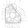
図10に示す如く、前記筒状部62の後端部には、基部63との接続部に、該筒状部62の外周面より外方に突出する補強部64が周方向に離間して複数形成される。また筒状部62の外周には、周方向に離間した複数の位置に、軸方向に沿って延在するリブ65が夫々突出形成されている。実施例では、図11に示す如く、4つのリブ65が周方向に等間隔で形成されている。なお、ハンドル装着部58には、筒状支持手段59における筒状部62の後部開口と対応する位置に通孔58aが開設され、ハンドルユニット20から導出する配線を裏側に引き出し得るようになっている。   As shown in FIG. 10, at the rear end of the tubular portion 62, a reinforcing portion 64 that protrudes outward from the outer peripheral surface of the tubular portion 62 is spaced apart in the circumferential direction at a connection portion with the base portion 63. A plurality are formed. Further, ribs 65 extending along the axial direction are formed on the outer periphery of the cylindrical portion 62 so as to protrude at a plurality of positions spaced apart in the circumferential direction. In the embodiment, as shown in FIG. 11, four ribs 65 are formed at equal intervals in the circumferential direction. The handle mounting portion 58 is provided with a through hole 58a at a position corresponding to the rear opening of the cylindrical portion 62 in the cylindrical support means 59 so that the wiring led out from the handle unit 20 can be drawn out to the back side. Yes.

前記筒状支持手段59は、図9に示す如く、前記ハンドル装着部58に基部63を固定した状態で、筒状部62の軸線が前側に向かうにつれて右側(中枠13の左右方向の中央から離間する側)に向けて傾斜するよう構成され、該筒状部62に筒部55aを挿通したハンドルユニット20も、前記把持キャップ56(ユニット20の軸線)が斜め右方を向く傾斜姿勢に保持される。   As shown in FIG. 9, the cylindrical support means 59 has a base 63 fixed to the handle mounting portion 58 and the right side (from the center in the left-right direction of the middle frame 13) as the axis of the cylindrical portion 62 moves forward. The handle unit 20 configured to incline toward the separating side and having the cylindrical portion 62a inserted through the cylindrical portion 62 is also held in an inclined posture in which the grip cap 56 (the axis of the unit 20) is directed obliquely to the right. Is done.

(ハンドル飾りについて)
前記ハンドル装着部58には、前記筒状支持手段59(ハンドルユニット20の筒状支持手段59に挿通されている根元)を囲う被覆部材としてのハンドル飾り66が配設される。ハンドル飾り66は、図9〜図11に示す如く、前記ハンドル装着部58に固定される基台部67と、該基台部67におけるハンドル装着部58の前面から離間する前壁68から前方に延在する筒状の筒受部69とを備え、該筒受部69に、前記筒状支持手段59の筒状部62が挿通される挿通孔69aが前後方向に貫通するよう形成されている。基台部67は、図11に示す如く、前記前壁68の外周縁から後方に延出する支持壁70を備え、前記ハンドル装着部58側に開口する箱状に形成されている。なお、実施例では、ハンドル飾り66の前壁68が、下辺が水平で、左右の辺が鉛直で、該左右の辺上端を接続する2つの上辺が山形に交差する正面視において5角形に形成されている。そして、前壁68における前記下球受け皿36側に位置する左辺および上左辺に設けられた支持壁70には、外方に延出する位置規制片71が一体に設けられ、前記中枠13に対して閉鎖状態とされた前記下球受け皿36の右板42bが位置規制片71の前側に臨むことで、当該ハンドル飾り66の前方への変位が規制されるようになっている。更に、位置規制片71および上右辺に設けられた支持壁70には、外方に延出するフランジ部72が夫々一体に設けられ、各フランジ部72の後面をハンドル装着部58の前面に当接した状態で、当該ハンドル飾り66が該ハンドル装着部58にネジ止め固定される。
(About handle decoration)
The handle mounting portion 58 is provided with a handle decoration 66 as a covering member surrounding the cylindrical support means 59 (the root inserted through the cylindrical support means 59 of the handle unit 20). As shown in FIGS. 9 to 11, the handle decoration 66 is forward from a base portion 67 fixed to the handle mounting portion 58 and a front wall 68 spaced from the front surface of the handle mounting portion 58 in the base portion 67. An extending tubular receiving portion 69 is formed, and an insertion hole 69a through which the tubular portion 62 of the tubular supporting means 59 is inserted penetrates the tubular receiving portion 69 in the front-rear direction. . As shown in FIG. 11, the base portion 67 includes a support wall 70 that extends rearward from the outer peripheral edge of the front wall 68 and is formed in a box shape that opens to the handle mounting portion 58 side. In the embodiment, the front wall 68 of the handle decoration 66 is formed in a pentagonal shape in front view in which the lower side is horizontal, the left and right sides are vertical, and the two upper sides connecting the upper ends of the left and right sides intersect each other in a mountain shape. Has been. A support wall 70 provided on the left side and the upper left side of the front wall 68 on the lower ball tray 36 side is integrally provided with a position restricting piece 71 extending outward, On the other hand, when the right plate 42b of the lower ball receiving tray 36 which is in a closed state faces the front side of the position restricting piece 71, the forward displacement of the handle decoration 66 is restricted. Further, the position restricting piece 71 and the support wall 70 provided on the upper right side are integrally provided with flange portions 72 extending outward, and the rear surface of each flange portion 72 is brought into contact with the front surface of the handle mounting portion 58. In the state of contact, the handle decoration 66 is fixed to the handle mounting portion 58 with screws.

前記ハンドル飾り66をハンドル装着部58に固定した状態で、図9に示す如く、前記前壁68は、前記筒受部69に向けてハンドル装着部58から前方に離間するように膨出しており、該前壁68の最前部に設けられた筒受部69の挿通孔69aに、前記筒状支持手段59の筒状部62が挿通支持されるよう構成される。筒受部69の挿通孔69aに挿通された筒状部62の外周面は、少なくとも筒受部69の前端内面に当接して、径方向への変位が規制された状態で支持される。すなわち、筒状支持手段59は、ハンドル装着部58に固定された基部63から前方に延出する端部側に偏倚した位置が、ハンドル飾り66の筒状部62で支持され、該筒状支持手段59は安定して支持されるようになっている。なお、ハンドル飾り66における筒受部69の挿通孔69aに筒状支持手段59の筒状部62が挿通された状態で、該筒受部69の前端は、筒状部62の前端と略同一位置に臨むよう構成される。また、ハンドル飾り66における前壁68のハンドルユニット20より左側の面(中枠13の左右方向の中央側の面)は、筒受部69(筒状支持手段59の筒状部62)から径方向の外方に離間するにつれて中枠13側に変位するよう形成される。これにより、ハンドルユニット20における前記操作片61と前壁68との間に、前記操作レバー57を操作している遊技者が操作片61を操作する指(親指)で、該操作片61を支障なく操作し得る操作用の空間を確保し得るようになっている。   With the handle decoration 66 fixed to the handle mounting portion 58, the front wall 68 bulges away from the handle mounting portion 58 toward the tube receiving portion 69 as shown in FIG. The cylindrical portion 62 of the cylindrical support means 59 is inserted and supported in the insertion hole 69a of the cylindrical receiving portion 69 provided in the foremost portion of the front wall 68. The outer peripheral surface of the cylindrical portion 62 inserted through the insertion hole 69a of the tube receiving portion 69 abuts at least the inner surface of the front end of the tube receiving portion 69 and is supported in a state where displacement in the radial direction is restricted. That is, the cylindrical support means 59 is supported by the cylindrical portion 62 of the handle decoration 66 at a position biased toward the end portion extending forward from the base portion 63 fixed to the handle mounting portion 58. The means 59 is supported stably. It should be noted that the front end of the tube receiving portion 69 is substantially the same as the front end of the tubular portion 62 in a state where the tubular portion 62 of the cylindrical support means 59 is inserted into the insertion hole 69 a of the tube receiving portion 69 in the handle decoration 66. Configured to face position. Further, the left surface of the front wall 68 of the handle decoration 66 from the handle unit 20 (the surface on the center side in the left-right direction of the middle frame 13) has a diameter from the tube receiving portion 69 (the tubular portion 62 of the tubular support means 59). It forms so that it may displace to the middle frame 13 side as it leaves | separates to the outward of a direction. As a result, a player operating the operation lever 57 between the operation piece 61 and the front wall 68 of the handle unit 20 with a finger (thumb) for operating the operation piece 61 obstructs the operation piece 61. An operation space that can be operated without any problem can be secured.

前記筒受部69の内面(挿通孔69aの内面)には、前記筒状支持手段59に形成した各リブ65と対応する位置の夫々に、該リブ65が嵌合する溝部69bが軸方向に延在するように形成される。すなわち、筒状支持手段59およびハンドル飾り66をハンドル装着部58に固定した状態では、図11に示す如く、複数のリブ65と溝部69bとが嵌合した状態で筒状支持手段59がハンドル飾り66で支持されるようになっている。なお、ハンドル飾り66の筒受部69は、前記ハンドルユニット20の筒部55aおよび筒状支持手段59の筒状部62に共通のネジで固定されている。   On the inner surface of the tube receiving portion 69 (the inner surface of the insertion hole 69a), groove portions 69b into which the ribs 65 are fitted in the positions corresponding to the ribs 65 formed in the cylindrical support means 59 are provided in the axial direction. It is formed to extend. That is, when the cylindrical support means 59 and the handle decoration 66 are fixed to the handle mounting portion 58, as shown in FIG. 11, the cylindrical support means 59 is attached to the handle decoration in a state where the plurality of ribs 65 and the groove portions 69b are fitted. 66 is supported. The tube receiving portion 69 of the handle decoration 66 is fixed to the tube portion 55a of the handle unit 20 and the tube portion 62 of the tube support means 59 with a common screw.

前記ハンドル飾り66における前壁68の裏面には、図12に示す如く、前記筒受部69を囲むように周方向に離間して複数の位置決めボス73が後方に向けて突設され、ハンドル飾り66をハンドル装着部58に固定した状態で、各位置決めボス73の後端がハンドル装着部58の前面に当接し、前壁68の後方への変位を規制するよう構成される。   As shown in FIG. 12, a plurality of positioning bosses 73 are provided on the back surface of the front wall 68 of the handle decoration 66 so as to surround the tube receiving portion 69 and protrude in the rear direction. In a state where 66 is fixed to the handle mounting portion 58, the rear end of each positioning boss 73 is in contact with the front surface of the handle mounting portion 58, and the rearward displacement of the front wall 68 is restricted.

前記位置規制片71は、支持壁70から外方にハンドル装着部58の前面に沿って延在する座部71aと、該座部71aの延出端縁から前側に向けて立設された立上がり部71bとから構成される。また位置規制片71は、前記下球受け皿36の右端縁をなす基体部42の右板42bの形状に対応して延在するよう構成されている。そして、位置規制片71の座部71aには、図9に示す如く、前記中枠13に対して閉鎖状態とされた下球受け皿36の右板42bの後端全面が当接するようになっている。また、右板42bと立上がり部71bとが左右方向で重なることで、下球受け皿36とハンドル飾り66との間からの異物侵入を防止し得るよう構成されている。なお、前壁68の上右辺に対応する支持壁70から延出するフランジ部72の前面には、前記施錠装置22を前側から覆う施錠カバー74(図1参照)が前側から当接している。   The position restricting piece 71 includes a seat 71a that extends outward from the support wall 70 along the front surface of the handle mounting portion 58, and a rising that is erected from the extending edge of the seat 71a toward the front side. Part 71b. The position restricting piece 71 is configured to extend in correspondence with the shape of the right plate 42 b of the base portion 42 that forms the right edge of the lower ball tray 36. As shown in FIG. 9, the entire rear end of the right plate 42 b of the lower ball tray 36 closed with respect to the middle frame 13 comes into contact with the seat 71 a of the position restricting piece 71. Yes. Further, the right plate 42b and the rising portion 71b overlap each other in the left-right direction so that entry of foreign matter from between the lower ball tray 36 and the handle decoration 66 can be prevented. A locking cover 74 (see FIG. 1) that covers the locking device 22 from the front side is in contact with the front surface of the flange portion 72 extending from the support wall 70 corresponding to the upper right side of the front wall 68 from the front side.

前記ハンドル飾り66における下側の支持壁70の下面には、該支持壁70の後端から前側に所要長偏倚した位置において下方に突出する第2の規制部(別の規制部)75が、左右方向の全長に亘って延在している。ハンドル飾り66は、図13に示す如く、下側の支持壁70における前記第2の規制部75から後方に延在する部分の下面が前記意匠板15の上面に上側で重なると共に、第2の規制部75が意匠板15の前面に重なって、ハンドル飾り66(支持壁70)の下面と意匠板15の上面との間に形成される隙間を前側から覆うよう構成される。また第2の規制部75は、前記閉鎖状態の下球受け皿36の第1の規制部49と左右方向に連なり、両規制部49,75の間からの異物侵入を防止するようになっている。   On the lower surface of the lower support wall 70 in the handle decoration 66, a second restricting portion (another restricting portion) 75 that protrudes downward at a position deviated by a required length from the rear end of the support wall 70 to the front side, It extends over the entire length in the left-right direction. As shown in FIG. 13, the handle decoration 66 has a lower surface of a portion of the lower support wall 70 extending rearward from the second restricting portion 75 that overlaps the upper surface of the design plate 15 on the upper side. The restricting portion 75 is configured to overlap the front surface of the design plate 15 so as to cover the gap formed between the lower surface of the handle decoration 66 (support wall 70) and the upper surface of the design plate 15 from the front side. The second restricting portion 75 is connected to the first restricting portion 49 of the lower ball tray 36 in the closed state in the left-right direction so as to prevent foreign matter from entering between the restricting portions 49 and 75. .

前記第2の規制部75は、前記第1の規制部49の構成と同じであって、下側の支持壁70から下方に突出する第1壁75aと、該第1壁75aの下端から後方に延在する第2壁75bとから後方に開放する縦断面L字状に形成される。また第2の規制部75には、支持壁70から下方に突出して第1壁75aおよび第2壁75bに接続する補強用リブ75cが、図12に示すように左右方向に離間して複数並設されている。   The second restricting portion 75 has the same configuration as that of the first restricting portion 49, and includes a first wall 75a protruding downward from the lower support wall 70, and a rear side from the lower end of the first wall 75a. The second wall 75b extending in the direction of L is formed in a longitudinal section L shape that opens rearward. The second restricting portion 75 has a plurality of reinforcing ribs 75c protruding downward from the support wall 70 and connected to the first wall 75a and the second wall 75b, spaced apart in the left-right direction as shown in FIG. It is installed.

〔実施例の作用〕
次に、前述した実施例に係るパチンコ機の作用につき説明する。
前記ハンドルユニット20の操作レバー57を回動操作することにより、前記球送り装置31が作動して上球受け皿30からパチンコ球が1球ずつ発射レールの打球発射位置に送り出されると共に、前記打球発射装置19が作動して打球発射位置にあるパチンコ球が遊技盤12の遊技領域12aに向けて打ち出される。遊技領域12aに打ち出されたパチンコ球が始動入賞装置に入賞すると、前記図柄表示装置28の図柄が変動開始され、所要の図柄組合わせゲームが展開される。図柄表示装置28で展開される図柄変動ゲームの結果、図柄表示装置28に所定の図柄組合わせで図柄が停止表示されたときに大当りが発生する。そして、大当りが発生すると、図柄表示装置28に表示された図柄組み合わせに応じて、前記遊技盤12の下方に設けられた特別入賞装置の入賞口が開放され、多数の賞球の獲得が可能となる。
(Effects of Example)
Next, the operation of the pachinko machine according to the above-described embodiment will be described.
When the operation lever 57 of the handle unit 20 is rotated, the ball feeding device 31 is actuated so that pachinko balls are sent from the upper ball receiving tray 30 one by one to the hitting position of the launching rail, and the hitting ball is launched. The device 19 is activated and a pachinko ball at the hitting position is launched toward the game area 12a of the game board 12. When the pachinko ball launched into the game area 12a wins the start winning device, the symbols on the symbol display device 28 start to fluctuate and a required symbol combination game is developed. As a result of the symbol variation game developed on the symbol display device 28, a big hit occurs when symbols are stopped and displayed on the symbol display device 28 in a predetermined symbol combination. When a big hit occurs, according to the symbol combination displayed on the symbol display device 28, the winning opening of the special winning device provided below the game board 12 is opened, and a large number of winning balls can be obtained. Become.

前記図柄表示装置28で展開される図柄変動ゲームの演出に応じて、前記各種の演出装置が作動制御されて、動作や光による演出により遊技の興趣が高められる。また、前記中枠13に設けられたスピーカ18から、図柄変動ゲームの演出に応じた効果音が出力されて、音による演出により遊技の興趣が向上される。   The various effect devices are controlled in accordance with the effects of the symbol variation game developed on the symbol display device 28, and the fun of the game is enhanced by the effects of motion and light. Further, a sound effect corresponding to the effect of the symbol variation game is output from the speaker 18 provided in the middle frame 13, and the entertainment of the game is improved by the effect by the sound.

前記スピーカ18は、前記中枠13の左下部に設けられた箱状部32のスピーカ収容室S2内に、前記蓋体34の出力孔35aを介して出力部18aが前面に露出する状態で収容されている。このスピーカ収容室S2は、前記意匠板15とボックスカバー16とにより画成された空間S1にダクト部16aを介して連通している。   The speaker 18 is accommodated in the speaker accommodating chamber S2 of the box-shaped portion 32 provided in the lower left portion of the middle frame 13 with the output portion 18a exposed to the front via the output hole 35a of the lid 34. Has been. The speaker housing chamber S2 communicates with a space S1 defined by the design plate 15 and the box cover 16 via a duct portion 16a.

すなわち、前記スピーカ18における出力部18aの前面から出力された音は、前記出力孔35aを通って前記下球受け皿36の音放出口44cから直接遊技者側に出力される。また、スピーカ18における出力部18aの背面から出力された音は、前記スピーカ収容部S2からダクト部16aおよび空間S1の夫々を通って下部放音口15cから遊技者側に放出される。実施例に係るパチンコ機10では、前記スピーカ18における出力部18aの背面から出力された音の経路が、バスレフ構造に形成されており、スピーカ18における出力部18aの背面から出力された音の低音域が増強されて、下部放音口15cから放出される音響効果の向上を図り得る。   That is, the sound output from the front surface of the output portion 18a of the speaker 18 is output directly to the player side through the output hole 35a and from the sound discharge port 44c of the lower ball tray 36. Further, the sound output from the back surface of the output portion 18a of the speaker 18 is emitted from the speaker housing portion S2 through the duct portion 16a and the space S1 to the player side from the lower sound outlet 15c. In the pachinko machine 10 according to the embodiment, the path of the sound output from the back surface of the output unit 18a in the speaker 18 is formed in a bass reflex structure, and the sound output from the back surface of the output unit 18a in the speaker 18 is low. The sound range is enhanced, and the acoustic effect emitted from the lower sound outlet 15c can be improved.

ここで、前記下球受け皿36は、メンテナンス等のために中枠13に対して開閉自在に支持され、両者13,36の対向面間には組付け誤差等に起因して隙間が生ずるのは避けられず、そのために前記スピーカ18における出力部18aの前面から出力される音が隙間から漏れて、音放出口44cから出力される音量や音質が低下するおそれがある。しかしながら、実施例のパチンコ機10では、前記下球受け皿36における音放出口44cの裏側に配設されて該音放出口44cを囲繞するよう配設された通路形成部材45の後端面に弾性変形可能なシール材48を配設し、中枠13に対して下球受け皿36を閉鎖した状態では、図5および図6に示す如く、スピーカ18の出力部18aが露出する出力孔35aの外周縁から突出する前記突出部35bの前面に前記シール材48が弾力的に当接し、スピーカ18の出力部18aから音放出口44cまでの空間を密閉するよう構成されている。従って、該出力部18aから出力された音が音放出口44c以外から外部に漏れるのを防ぐことができ、音放出口44cから出力される音量や音質の低下を防止し得る。なお、シール材48としてスポンジを用いることにより、シール材48を突出部35bに当接した際には該シール材48が圧縮変形して密閉度が向上し、音漏れを確実に防ぐことができる。   Here, the lower ball tray 36 is supported so as to be openable and closable with respect to the middle frame 13 for maintenance and the like, and a gap is generated between the opposing surfaces of the both 13, 36 due to an assembly error or the like. For this reason, the sound output from the front surface of the output unit 18a of the speaker 18 may leak from the gap, and the volume and sound quality output from the sound emission port 44c may be reduced. However, in the pachinko machine 10 according to the embodiment, the rear end surface of the passage forming member 45 disposed on the back side of the sound discharge port 44c in the lower ball tray 36 and disposed so as to surround the sound discharge port 44c is elastically deformed. In the state where the possible sealing material 48 is disposed and the lower ball tray 36 is closed with respect to the inner frame 13, as shown in FIGS. 5 and 6, the outer peripheral edge of the output hole 35a where the output portion 18a of the speaker 18 is exposed. The sealing material 48 is elastically brought into contact with the front surface of the projecting portion 35b projecting from the space, and the space from the output portion 18a of the speaker 18 to the sound emission port 44c is sealed. Therefore, the sound output from the output unit 18a can be prevented from leaking outside from the sound emission port 44c, and the volume and sound quality output from the sound emission port 44c can be prevented. By using a sponge as the sealing material 48, when the sealing material 48 comes into contact with the projecting portion 35b, the sealing material 48 is compressed and deformed to improve the sealing degree, and sound leakage can be reliably prevented. .

また、前記スピーカ18は、前記箱状部32を構成する蓋体34に裏側から取付けられ、出力部18aを該蓋体34に開設された出力孔35aでのみ前側に露出するよう構成してあるから、該出力部18aを前後で確実に仕切ることができ、出力部18aの背面から出る音の影響によって音放出口44cから放出される音量や音質が低下するのを防止し得る。   The speaker 18 is attached to the lid 34 constituting the box-shaped portion 32 from the back side, and the output portion 18a is exposed to the front side only through the output hole 35a provided in the lid 34. Therefore, the output unit 18a can be reliably partitioned in the front and rear, and the volume and sound quality emitted from the sound emission port 44c can be prevented from being lowered due to the influence of the sound emitted from the back surface of the output unit 18a.

前記下球受け皿36の音放出口44cは、前述したように、左右方向においてパチンコ機10の左右方向の中央側を向くと共に、上下方向において前記前枠14のガラス板(可視部)14a側を向く第1傾斜面部44aに形成されて、概ねガラス板(可視部)14aの正面中央側を向くよう開設されている。また、前記スピーカ18の出力部18aに対向する通路形成部材45の前壁46は、図6に示す如く、前記音放出口44cに対応する音放出口46cが開設された右側の第1傾斜面46aの左側に、左下側に向けて後方傾斜する第2傾斜面46bが形成されており、出力部18aから出力されて第2傾斜面46bに当たった音は、第1傾斜面46a側に向けて斜めに反射される(図8(b),(c)参照)。すなわち、第2傾斜面46bで反射した音は、音放出口46cおよび音放出口44cから、該放出口46c,44cが向く、パチンコ機10の正面に座って遊技を行なう平均的な体格の遊技者の頭部側に向けて音が放出される。従って、隣接するパチンコ機から出る効果音や場内放送等が流れている状況であっても、遊技者は自分が遊技しているパチンコ機10からの効果音を認識することができ、前記図柄変動ゲームの演出にマッチした臨場感や迫力に富む効果音を体感できる。   As described above, the sound discharge port 44c of the lower ball receiving tray 36 faces the center side in the left-right direction of the pachinko machine 10 in the left-right direction, and faces the glass plate (visible part) 14a side of the front frame 14 in the up-down direction. It is formed in the 1st inclined surface part 44a which faces, and it is opened so that it may face the front center side of the glass plate (visible part) 14a in general. Further, the front wall 46 of the passage forming member 45 facing the output portion 18a of the speaker 18 is, as shown in FIG. 6, the first inclined surface on the right side where the sound emission port 46c corresponding to the sound emission port 44c is opened. A second inclined surface 46b that is inclined backward toward the lower left side is formed on the left side of 46a, and the sound that is output from the output unit 18a and hits the second inclined surface 46b is directed toward the first inclined surface 46a. Are reflected obliquely (see FIGS. 8B and 8C). That is, the sound reflected by the second inclined surface 46b is a game of an average physique where a player sits in front of the pachinko machine 10 and plays from the sound outlet 46c and the sound outlet 44c toward the outlets 46c and 44c. Sound is emitted toward the person's head. Therefore, even in a situation where sound effects from the adjacent pachinko machines, in-site broadcasts, and the like are flowing, the player can recognize the sound effects from the pachinko machine 10 that he / she is playing, and the pattern variation Experience realistic sounds and powerful sound effects that match the game production.

すなわち、第2傾斜面46bで音を反射することで、前記第1傾斜面46aおよび第1傾斜面部44aの音放出口46c,44cから、パチンコ機10の正面に座った遊技者の頭部側に向けて効率的に音を放出することができる。また、スピーカ18の出力部18aと第2傾斜面46bとは直接対向しているので、出力部18aから出力された音が第2傾斜面46bまで至る間に他の部材に反射等して減衰することはなく、出力部18aから出力された音を音放出口46c,44cから効率的に放出し得る。更に、実施例では、パチンコ機10のガラス板14aから外れた左下部に設けたスピーカ18を、出力部18aが正面を向く姿勢で配置したもとで、該出力部18aから出力された音をガラス板14aの中央正面側に向けて放出し得るようにしたので、スピーカ18の姿勢を変えて対応する場合に比べて、該スピーカ18の設置部での前後寸法を小さく抑えることができる。   That is, by reflecting the sound on the second inclined surface 46b, the head side of the player sitting in front of the pachinko machine 10 from the sound emitting ports 46c and 44c of the first inclined surface 46a and the first inclined surface portion 44a. Sound can be emitted efficiently toward Further, since the output portion 18a of the speaker 18 and the second inclined surface 46b are directly opposed to each other, the sound output from the output portion 18a is reflected by other members and attenuated while reaching the second inclined surface 46b. The sound output from the output unit 18a can be efficiently emitted from the sound emission ports 46c and 44c. Further, in the embodiment, the speaker 18 provided in the lower left part off the glass plate 14a of the pachinko machine 10 is arranged with the output unit 18a facing the front, and the sound output from the output unit 18a is output. Since it can discharge | emit toward the center front side of the glass plate 14a, the front-back dimension in the installation part of this speaker 18 can be restrained small compared with the case where the attitude | position of the speaker 18 is changed and it respond | corresponds.

前記下球受け皿36における前記音放出口44cの形成位置の右側において前方に大きく膨出している前記膨出部43は、図5に示す如く、音放出口44cに近接する左端部の上端面位置が、該音放出口44cの上下方向の略中間に位置しており、音放出口44cの約上半分の領域から放出される音は、膨出部43に遮られることなく遊技者の頭部側(ガラス板14aの中央正面側)へ至る。また、音放出口44cの約下半分の領域から放出される音は、図8(b)に示す如く、膨出部43の前記傾斜案内面43aで反射して、音放出口44cの約上半分の領域から放出される音とは異なる方向に向かう。すなわち、音放出口44cから放出される音は、パチンコ機10の正面に座った遊技者の異なる位置に向かい、1つのスピーカ18での音響効果を向上し得る。なお、実施例では、前記第2傾斜面部44bにも音放出口44cの一部が開口しており(図8(a)参照)、該開口部からの音の放出方向も異なることから、より広範囲に音を放出することができる。   As shown in FIG. 5, the bulging portion 43 that bulges largely forward on the right side of the formation position of the sound discharge port 44c in the lower ball tray 36 is located at the upper end surface position of the left end portion close to the sound discharge port 44c. However, the sound emitted from the upper half region of the sound discharge port 44c is not blocked by the bulging portion 43 and is not blocked by the bulge portion 43. To the side (center front side of the glass plate 14a). Further, as shown in FIG. 8 (b), the sound emitted from the lower half area of the sound emission port 44c is reflected by the inclined guide surface 43a of the bulging portion 43, and approximately above the sound emission port 44c. The direction is different from the sound emitted from the half area. In other words, the sound emitted from the sound emission port 44 c is directed to different positions of the player sitting in front of the pachinko machine 10, and the acoustic effect at one speaker 18 can be improved. In the embodiment, a part of the sound emission port 44c is also opened in the second inclined surface part 44b (see FIG. 8A), and the direction of sound emission from the opening part is also different. Sound can be emitted over a wide range.

前記ハンドルユニット20を中枠13に固定するための前記筒状支持手段59は、前記筒状部62が、図9および図11に示す如く、前記ハンドル飾り66における筒受部69の挿通孔69aに挿通支持され、かつ筒状部62のリブ65が筒受部69の溝部69bに嵌合支持されることで、該筒状支持手段59の剛性が高められている。従って、ハンドルユニット20を把持して中枠13を開閉する操作を繰り返しても、筒状支持手段59が変形したり破損するのを防止することができ、ハンドルユニット20の適正な配設状態を長期に亘って維持できる。すなわち、ハンドルユニット20の位置や姿勢が変化することで操作性が低下するのを防止し得る。   The cylindrical support means 59 for fixing the handle unit 20 to the middle frame 13 is such that the cylindrical portion 62 has an insertion hole 69a of the cylindrical receiving portion 69 in the handle decoration 66 as shown in FIGS. Since the rib 65 of the cylindrical part 62 is fitted and supported in the groove part 69b of the cylindrical receiving part 69, the rigidity of the cylindrical support means 59 is enhanced. Accordingly, even when the operation of holding the handle unit 20 and opening and closing the middle frame 13 is repeated, the cylindrical support means 59 can be prevented from being deformed or damaged, and the proper arrangement state of the handle unit 20 can be prevented. It can be maintained for a long time. That is, it is possible to prevent the operability from being deteriorated due to a change in the position or posture of the handle unit 20.

前記リブ65および溝部69bは軸方向に所要長さで延在しているから、該リブ65および溝部69bの嵌合領域が長く、筒状支持手段59の剛性をより高めることができる。また、リブ65および溝部69bは周方向に定間隔で複数設けられているので、更に筒状支持手段59の剛性を向上し得る。なお、前記ハンドルユニット20が凹溝55bと凸条62aとの嵌合によって回り止めされている筒状支持手段59に加わる回転方向の負荷を、前記リブ65と溝部69bとが嵌合しているハンドル飾り66でも支持することができるから、筒状支持手段59に加わる負荷を軽減して耐久性を向上し得る。また、筒状支持手段59は、筒状部62の後端において径方向外方に延在する基部63でハンドル装着部58に固定されており、該筒状支持手段59のハンドル装着部58に対する取付け強度は高く、ハンドル装着部58から前方に延出する筒状部62は強固に支持される。しかも、基部63と筒状部62との接続部は、図10に示す如く、複数の補強部64により接続強度が高められているから、該接続部での変形や破損等を確実に防止し得る。   Since the rib 65 and the groove 69b extend in the axial direction with a required length, the fitting region of the rib 65 and the groove 69b is long, and the rigidity of the cylindrical support means 59 can be further increased. Further, since a plurality of ribs 65 and groove portions 69b are provided at regular intervals in the circumferential direction, the rigidity of the cylindrical support means 59 can be further improved. The rib 65 and the groove 69b are fitted to a rotational load applied to the cylindrical support means 59 in which the handle unit 20 is prevented from rotating by fitting the concave groove 55b and the ridge 62a. Since the handle decoration 66 can also be supported, the load applied to the cylindrical support means 59 can be reduced and the durability can be improved. The cylindrical support means 59 is fixed to the handle mounting portion 58 with a base 63 extending radially outward at the rear end of the cylindrical portion 62, and the cylindrical support means 59 is connected to the handle mounting portion 58. The attachment strength is high, and the cylindrical portion 62 extending forward from the handle mounting portion 58 is firmly supported. In addition, since the connection strength of the connecting portion between the base portion 63 and the cylindrical portion 62 is enhanced by a plurality of reinforcing portions 64 as shown in FIG. 10, it is possible to reliably prevent deformation and breakage at the connecting portion. obtain.

前記ハンドル飾り66では、図9に示す如く、前記前壁68に設けた筒受部69で筒状支持手段59における筒状部62の前端側を支持している。すなわち、ハンドルユニット20の筒部55aを挿通支持している筒状部62は、ハンドル装着部58に固定された基部63と、該基部63から前方に離間する前端側との2箇所で支持されているから、該筒状部62に加わる負荷を分散して支持することができ、該筒状部62の変形や破損等を防止し、ハンドルユニット20の適正な配設状態を長期に亘って維持できる。   As shown in FIG. 9, the handle decoration 66 supports the front end side of the tubular portion 62 of the tubular support means 59 by a tubular receiving portion 69 provided on the front wall 68. That is, the cylindrical portion 62 that inserts and supports the cylindrical portion 55a of the handle unit 20 is supported at two locations: a base portion 63 that is fixed to the handle mounting portion 58, and a front end side that is spaced forward from the base portion 63. Therefore, the load applied to the cylindrical portion 62 can be dispersed and supported, the deformation and damage of the cylindrical portion 62 can be prevented, and the proper arrangement state of the handle unit 20 can be maintained for a long time. Can be maintained.

ここで、前記ハンドル飾り66の前壁68は、図9に示す如く、前記筒受部69で筒状部62の前端側を支持するべくハンドル装着部58から筒受部69に向けて前方に膨出して、前記ハンドルユニット20における遊技者が把持する操作レバー57の近くに位置している。しかし、前壁68におけるハンドルユニット20より左側の面は、筒受部69から径方向の外方に離間するにつれて中枠13側に変位するよう形成されて、ハンドルユニット20における前記操作片61と前壁68との間に操作用の空間を確保している。すなわち、ハンドルユニット20の操作レバー57を把持した遊技者が、親指で操作片61を操作する際にハンドル飾り66の前壁68に該親指が接触して操作性が低下したり、操作片61が操作し難くなるのを防止しつつ、筒状支持手段59をハンドル飾り66で安定して支持することができる。   Here, as shown in FIG. 9, the front wall 68 of the handle decoration 66 is moved forward from the handle mounting portion 58 toward the tube receiving portion 69 so as to support the front end side of the tubular portion 62 by the tube receiving portion 69. The handle unit 20 bulges and is positioned near the operation lever 57 held by the player. However, the surface on the left side of the handle unit 20 in the front wall 68 is formed so as to be displaced toward the middle frame 13 as it is spaced radially outward from the tube receiving portion 69, and the operation piece 61 in the handle unit 20. A space for operation is secured between the front wall 68 and the front wall 68. That is, when the player holding the operation lever 57 of the handle unit 20 operates the operation piece 61 with the thumb, the thumb comes into contact with the front wall 68 of the handle decoration 66 and the operability is reduced. It is possible to stably support the cylindrical support means 59 with the handle decoration 66 while preventing the operation from becoming difficult.

前記ハンドル飾り66は、前記中枠13に対する前記下球受け皿36の閉鎖状態で、図9に示す如く、前記基台部67の位置規制片71の座部71aに下球受け皿36の右板42bが前側から当接すると共に、上側のフランジ部72に前記施錠カバー74が前側から当接している。すなわち、前記ハンドルユニット20を把持して中枠13を外枠11に対して開放する際には、ハンドルユニット20を介してハンドル飾り66に加わる前方への負荷を下球受け皿36や施錠カバー74によって支持することができ、該ハンドル飾り66の変形や破損を防止し得る。また、前壁68の裏面において筒受部69を囲むように突設された複数の位置決めボス73の後端がハンドル装着部58の前面に当接しているから、ハンドルユニット20を把持して中枠13を外枠11に対して閉成する際に加わるハンドル飾り66への負荷を、複数の位置決めボス73を介してハンドル装着部58で支持することができ、特に前壁68の変形や破損を防止し得る。   As shown in FIG. 9, the handle decoration 66 is in the closed state of the lower ball tray 36 with respect to the middle frame 13, and the right plate 42 b of the lower ball tray 36 on the seat 71 a of the position restricting piece 71 of the base 67. Is in contact with the upper flange portion 72 from the front side. That is, when the handle unit 20 is gripped and the middle frame 13 is released from the outer frame 11, a forward load applied to the handle decoration 66 via the handle unit 20 is applied to the lower ball tray 36 and the locking cover 74. The handle decoration 66 can be prevented from being deformed or damaged. Further, since the rear ends of the plurality of positioning bosses 73 projecting so as to surround the tube receiving portion 69 on the back surface of the front wall 68 are in contact with the front surface of the handle mounting portion 58, A load applied to the handle decoration 66 applied when the frame 13 is closed with respect to the outer frame 11 can be supported by the handle mounting portion 58 via a plurality of positioning bosses 73, and in particular, deformation or breakage of the front wall 68. Can prevent.

前記外枠11に対して中枠13を開閉する構成では、該中枠13を外枠11内に収容するために、中枠13の下枠体13bの下面と前記意匠板15の上面との間に干渉防止用の隙間を設ける必要があり、該隙間を介して異物を侵入させる等の不正行為が行なわれる可能性が高くなる。しかるに実施例では、前記中枠13の前面下部に配設した下球受け皿36の下面に、図5(b)に示す如く、外枠11に対する中枠13の閉鎖状態で意匠板15の前面に重なって隙間を覆う第1の規制部49を突設したから、異物を侵入させるのを簡単な構成で確実に防止し得る。しかも、中枠13と意匠板15との隙間は、第1の規制部49によって隠されているから、不正者が不正行為を行なうこと自体を思い止まらせることができる。   In the configuration in which the middle frame 13 is opened and closed with respect to the outer frame 11, the lower surface of the lower frame body 13 b of the middle frame 13 and the upper surface of the design plate 15 are disposed in order to accommodate the middle frame 13 in the outer frame 11. It is necessary to provide a gap for preventing interference between them, and there is a high possibility that a fraudulent act such as a foreign substance entering through the gap is performed. However, in the embodiment, on the lower surface of the lower ball tray 36 disposed in the lower front portion of the middle frame 13, on the front surface of the design plate 15 with the middle frame 13 closed with respect to the outer frame 11 as shown in FIG. Since the first restricting portion 49 that overlaps and covers the gap protrudes, it is possible to reliably prevent foreign matter from entering with a simple configuration. In addition, since the gap between the middle frame 13 and the design plate 15 is hidden by the first restricting portion 49, it is possible to discourage the fraudulent acts themselves.

また実施例では、下球受け皿36に並んで中枠13に設けられるハンドルユニット20の根元部分を覆っているハンドル飾り66の下面に第2の規制部75を設け、図13(b)に示す如く、該第2の規制部75によっても中枠13と意匠板15との隙間を前側から覆うよう構成している。従って、中枠13の幅方向の全長に亘って意匠板15との隙間からの不正行為を防止し得ると共に、不正者が不正行為を行なうこと自体を確実に思い止まらせることができる。なお実施例では、下球受け皿36の閉鎖状態で、図9に示す如く、前記右板42bが、ハンドル飾り66の位置規制片71における立上がり部71bの右側に位置して左右方向で重なっているから、両者36,66との間に異物を侵入させる不正行為も防止し得る。すなわち、外枠11に対して中枠13を開閉自在に支持する構成において、該中枠13の下部側での充分な不正対策が施されている。   Further, in the embodiment, the second restricting portion 75 is provided on the lower surface of the handle decoration 66 covering the base portion of the handle unit 20 provided on the inner frame 13 along with the lower ball tray 36, as shown in FIG. As described above, the second restricting portion 75 is also configured to cover the gap between the middle frame 13 and the design plate 15 from the front side. Accordingly, it is possible to prevent fraud from the gap with the design plate 15 over the entire length of the middle frame 13 in the width direction, and it is possible to reliably discourage fraudulent acts themselves. In the embodiment, when the lower ball tray 36 is closed, the right plate 42b is positioned on the right side of the rising portion 71b of the position restricting piece 71 of the handle decoration 66 and overlaps in the left-right direction as shown in FIG. Therefore, it is possible to prevent an illegal act of entering a foreign object between the two 36 and 66. That is, in the configuration in which the middle frame 13 is supported so as to be openable and closable with respect to the outer frame 11, sufficient countermeasures against improperness are taken on the lower side of the middle frame 13.

前記中枠13は、前記外枠11から取り外された状態で保管される場合があり、この保管時には下枠体13bを床に置いた状態とされる。このとき、下枠体13bの下部に配設された前記下球受け皿36やハンドル飾り66の下面に設けた前記規制部49,75が床に接することになる。この規制部49,75には、複数の補強用リブ50,75cが形成されているから強度は高く、該規制部49,75が変形したり破損するのは防止される。従って、規制部49,75が変形したり破損することで、外枠11に中枠13を取付けた際に該規制部49,75が不正防止機能を果たさなくなるのを防ぐことができる。なお、実施例では、補強のために複数の補強用リブ50,75cを並設する構成を採用しているから、規制部49,75を中実に形成した場合に比べて材料費を低減し得ると共に軽量化を図ることができる。   The middle frame 13 may be stored in a state where it is removed from the outer frame 11, and the lower frame body 13b is placed on the floor at the time of storage. At this time, the restricting portions 49 and 75 provided on the lower surfaces of the lower ball tray 36 and the handle decoration 66 disposed at the lower part of the lower frame 13b come into contact with the floor. Since the restricting portions 49 and 75 are formed with a plurality of reinforcing ribs 50 and 75c, the strength is high, and the restricting portions 49 and 75 are prevented from being deformed or damaged. Therefore, the restricting portions 49 and 75 can be prevented from being deformed or damaged, so that when the middle frame 13 is attached to the outer frame 11, the restricting portions 49 and 75 do not perform the fraud prevention function. In the embodiment, since a configuration in which a plurality of reinforcing ribs 50 and 75c are arranged side by side is used for reinforcement, the material cost can be reduced as compared with the case where the restricting portions 49 and 75 are solidly formed. At the same time, the weight can be reduced.

(変更例)
本願は前述した実施例の構成に限定されるものではなく、その他の構成を適宜に採用することができる。
(1) 実施例では、中枠の左下部にスピーカを配設したが、右下部に配設してもよく、この場合に下球受け皿に形成される音放出口を左斜め上方(ガラス板の正面中央側)を向くように開設すればよい。また、スピーカを前枠の角部に配設し、該スピーカを覆う被覆部材としての装飾部材に、ガラス板の正面中央側を向く音放出口を開設する構成等を採用し得る。
(2) 実施例では、スピーカの出力部から出力された音を音放出口に案内する通路形成壁を下球受け皿とは別部材である通路形成部材で構成したが、下球受け皿に通路形成壁を一体で形成した構成を採用し得る。この場合は、下球受け皿の第2傾斜面部が、スピーカの出力部から出力された音を音放出口に向けて反射する傾斜面となる。
(3) 実施例では、中枠における下球受け皿で前側が覆われる位置にスピーカを配設したが、該スピーカを前枠(開閉部材)で前側が覆われる位置に配設し、中枠に対する前枠の閉鎖状態で該前枠のスピーカと対向する位置に音放出口、通路形成壁およびシール材を設ける構成を採用し得る。
(4) 実施例では、スピーカを、出力部が真っ直ぐ前を向く姿勢で配置し、該出力部から前側に出力した音を、第2傾斜面(傾斜面)で反射することで音放出口からガラス板の正面中央側に向けて放出するよう構成したが、出力部と音放出口とが正対する姿勢でスピーカを配置し、出力部で出力した音が、直接音放出口からガラス板の正面中央側に向けて放出される構成を採用し得る。
(5) 実施例では、筒状支持手段に設けたリブをハンドル飾りに設けた溝部に嵌合したが、筒状支持手段に溝部を設けると共にハンドル飾りにリブを設ける構成を採用し得る。またリブおよび溝部の数や配設間隔は、実施例に限定されるものでなく、任意に設定可能である。
(6) 実施例では、ハンドルユニットを中枠の右下部に配設したが、左下部に配設してもよく、この場合にはハンドル飾りの前壁におけるハンドルユニットより右側の面を径方向の外方に離間するにつれて中枠側に変位するよう形成すればよい。
(7) 実施例では、中枠と一体的に開閉する下球受け皿の下面に規制部を設けたが、例えば前枠の下面に規制部を設け、該前枠を中枠に対して閉鎖状態とした際に、前枠の下面が下球受け皿の上面と上下の関係で重なると共に、両面間の隙間を前枠下面に設けた規制部で前側から覆う構成であってもよい。そして、第1部材および第2部材との関係は、下球受け皿と意匠板との関係、前枠と下球受け皿との関係に限られるものでなく、上下の関係で相対的に開閉自在に支持される関係となっているものであれば、遊技機のその他の構成部品であってもよい。
(8) 遊技機としては、パチンコ機に限られるものではなく、アレンジボール機やパチンコ球を用いたスロットマシン等、その他各種の遊技機であってもよい。
(Example of change)
The present application is not limited to the configuration of the above-described embodiment, and other configurations can be appropriately employed.
(1) In the embodiment, the speaker is arranged in the lower left part of the middle frame, but it may be arranged in the lower right part. Open the front center side of Moreover, the structure etc. which arrange | position a speaker to the corner | angular part of a front frame, and open the sound emission opening which faces the front center side of a glass plate can be employ | adopted for the decoration member as a coating | coated member which covers this speaker.
(2) In the embodiment, the passage forming wall that guides the sound output from the output portion of the speaker to the sound emitting port is configured by a passage forming member that is a separate member from the lower sphere tray, but the passage is formed in the lower sphere tray. A configuration in which the walls are integrally formed may be employed. In this case, the 2nd inclined surface part of a lower ball saucer turns into an inclined surface which reflects the sound output from the output part of the speaker toward the sound discharge port.
(3) In the embodiment, the speaker is disposed at a position where the front side is covered by the lower ball tray in the middle frame, but the speaker is disposed at a position where the front side is covered by the front frame (opening / closing member), A configuration in which a sound emission port, a passage forming wall, and a sealing material are provided at a position facing the speaker of the front frame in the closed state of the front frame may be employed.
(4) In the embodiment, the speaker is arranged in a posture in which the output unit faces straight forward, and the sound output to the front side from the output unit is reflected by the second inclined surface (inclined surface) to be emitted from the sound emission port. Although it is configured to emit toward the front center side of the glass plate, the speaker is placed in a posture where the output unit and the sound emission port face each other, and the sound output from the output unit is directly from the sound emission port to the front of the glass plate. The structure discharged | emitted toward the center side may be employ | adopted.
(5) In the embodiment, the rib provided on the cylindrical support means is fitted in the groove provided on the handle decoration, but a configuration in which the groove is provided on the cylindrical support means and the rib is provided on the handle decoration can be adopted. Further, the number of ribs and grooves and the arrangement interval are not limited to those in the embodiment, and can be arbitrarily set.
(6) In the embodiment, the handle unit is arranged at the lower right part of the middle frame, but it may be arranged at the lower left part. In this case, the surface on the right side of the handle unit on the front wall of the handle decoration is arranged in the radial direction. What is necessary is just to form so that it may displace to the middle frame side as it leaves | separates outward.
(7) In the embodiment, the restricting portion is provided on the lower surface of the lower ball tray that opens and closes integrally with the inner frame. For example, the restricting portion is provided on the lower surface of the front frame, and the front frame is closed with respect to the inner frame. In this case, the lower surface of the front frame may overlap with the upper surface of the lower ball tray in a vertical relationship, and the gap between both surfaces may be covered from the front side with a restriction portion provided on the lower surface of the front frame. The relationship between the first member and the second member is not limited to the relationship between the lower ball tray and the design plate and the relationship between the front frame and the lower ball tray, but can be opened and closed relatively in an up-and-down relationship. Other components of the gaming machine may be used as long as they are in a supported relationship.
(8) The gaming machine is not limited to a pachinko machine, and may be other various gaming machines such as an arrangement ball machine or a slot machine using a pachinko ball.

11 外枠(固定枠)
12 遊技盤
13 中枠(本体枠)
20 ハンドルユニット
59 筒状支持手段
62 筒状部
63 基部
64 補強部
65 リブ
66 ハンドル飾り(被覆部材)
69 筒受部
69a 挿通孔
69b 溝部
11 Outer frame (fixed frame)
12 Game board 13 Middle frame (main frame)
20 Handle unit 59 Cylindrical support means 62 Cylindrical part 63 Base 64 Reinforcement part 65 Rib 66 Handle decoration (covering member)
69 Tube receiving part 69a Insertion hole 69b Groove part

Claims (5)

遊技盤が配設される本体枠が固定枠に対して開閉自在に支持され、前記本体枠の前側に打球発射用のハンドルユニットが配設された遊技機において、
前記本体枠から前方に向けて筒状に延出し、前記ハンドルユニットを挿通状態で支持する筒状支持手段と、
前記本体枠に設けられて前記筒状支持手段を囲う被覆部材と、
前記被覆部材の前後に貫通し、前記筒状支持手段が挿通される挿通孔と、
前記筒状支持手段の外面および被覆部材における挿通孔の内面との一方の面に突設されたリブおよび他方の面に形成されて該リブが嵌合する溝部とを備え、
前記リブと溝部とが嵌合した状態で前記筒状支持手段の延出端部を、前記挿通孔の前端内面に当接した状態で被覆部材により支持するよう構成され、
前記挿通孔は周方向において前後方向の長さが異なるように形成され、前記筒状支持手段の延出端部における筒状支持手段の外周面と、前記挿通孔の前端内面との当接長さが、該筒状支持手段の周方向で異なるように構成した
ことを特徴とする遊技機。
In a gaming machine in which a body frame on which a game board is disposed is supported so as to be openable and closable with respect to a fixed frame, and a handle unit for hitting a ball is disposed on the front side of the body frame,
A cylindrical support means that extends forward from the main body frame and supports the handle unit in an inserted state;
A covering member provided on the main body frame and surrounding the cylindrical support means;
An insertion hole that penetrates the front and rear of the covering member and through which the cylindrical support means is inserted
A rib projecting on one surface of the outer surface of the cylindrical support means and an inner surface of the insertion hole in the covering member, and a groove formed on the other surface and fitted with the rib,
The extended end portion of said tubular supporting means in a state where said rib and groove fitted, is so that configured to support the cover member in contact with the front end inner surface of the insertion hole,
The insertion hole is formed to have different lengths in the front-rear direction in the circumferential direction, and the contact length between the outer peripheral surface of the cylindrical support means at the extending end of the cylindrical support means and the inner surface of the front end of the insertion hole A gaming machine , wherein the length of the cylindrical support means is different in the circumferential direction .
前記被覆部材は、前記筒状支持手段の軸方向に所定長さで延在して前記挿通孔が形成される筒受部を備え、該筒受部の延在方向に沿って前記リブおよび溝部が形成される請求項1記載の遊技機。   The covering member includes a tube receiving portion that extends in a predetermined length in the axial direction of the cylindrical support means to form the insertion hole, and the rib and the groove portion along the extending direction of the tube receiving portion. The gaming machine according to claim 1, wherein: is formed. 前記リブおよび溝部は、前記筒状支持手段の周方向に離間した位置に、該筒状支持手段の軸方向へ延在するよう複数形成される請求項1または2記載の遊技機。   The gaming machine according to claim 1 or 2, wherein a plurality of the ribs and the groove portions are formed so as to extend in the axial direction of the cylindrical support means at positions spaced apart in the circumferential direction of the cylindrical support means. 前記筒状支持手段は、前記ハンドルユニットを挿通状態で支持すると共に前記リブまたは溝部が形成された筒状部と、該筒状部における本体枠側の端部に設けられて前記ハンドルユニットの挿通方向と交差する外方へ延出する基部とを備え、該筒状支持手段は基部が前記本体枠に着脱自在に取付けられる請求項1〜3の何れか一項に記載の遊技機。   The cylindrical support means supports the handle unit in an inserted state and is provided at a cylindrical portion in which the rib or groove is formed and an end portion of the cylindrical portion on the main body frame side. The gaming machine according to any one of claims 1 to 3, further comprising a base portion extending outwardly intersecting the direction, wherein the base portion is detachably attached to the main body frame. 前記筒状部と基部との接続部に、該筒状部の外周面より外方に突出する補強部が周方向に離間して複数形成される請求項4記載の遊技機。   The gaming machine according to claim 4, wherein a plurality of reinforcing portions protruding outward from the outer peripheral surface of the cylindrical portion are formed in the connecting portion between the cylindrical portion and the base portion so as to be spaced apart in the circumferential direction.
JP2011043249A 2011-02-28 2011-02-28 Game machine Active JP5639504B2 (en)

Priority Applications (1)

Application Number Priority Date Filing Date Title
JP2011043249A JP5639504B2 (en) 2011-02-28 2011-02-28 Game machine

Applications Claiming Priority (1)

Application Number Priority Date Filing Date Title
JP2011043249A JP5639504B2 (en) 2011-02-28 2011-02-28 Game machine

Publications (2)

Publication Number Publication Date
JP2012179156A JP2012179156A (en) 2012-09-20
JP5639504B2 true JP5639504B2 (en) 2014-12-10

Family

ID=47010959

Family Applications (1)

Application Number Title Priority Date Filing Date
JP2011043249A Active JP5639504B2 (en) 2011-02-28 2011-02-28 Game machine

Country Status (1)

Country Link
JP (1) JP5639504B2 (en)

Families Citing this family (1)

* Cited by examiner, † Cited by third party
Publication number Priority date Publication date Assignee Title
JP6718292B2 (en) * 2016-04-19 2020-07-08 株式会社平和 Amusement machine

Family Cites Families (5)

* Cited by examiner, † Cited by third party
Publication number Priority date Publication date Assignee Title
JPH105396A (en) * 1996-06-21 1998-01-13 Sanyo Bussan Kk Handle holding structure for pachinko machine
JP2006263060A (en) * 2005-03-23 2006-10-05 Naito Shokai:Kk Fitting structure of operation handle for game machine
JP5128788B2 (en) * 2006-07-07 2013-01-23 株式会社ソフイア Game machine
JP4359602B2 (en) * 2006-07-14 2009-11-04 株式会社内藤商会 Bullet ball machine
JP4912793B2 (en) * 2006-08-28 2012-04-11 株式会社足立ライト工業所 Game machine

Also Published As

Publication number Publication date
JP2012179156A (en) 2012-09-20

Similar Documents

Publication Publication Date Title
JP5441089B2 (en) Winning units and gaming machines
JP6318598B2 (en) Game machine
JP6269020B2 (en) Game machine
JP2015029556A (en) Game machine
JP2021180923A (en) Game machine
JP4787849B2 (en) Game machine
JP5639505B2 (en) Game machine
JP4058495B2 (en) Game machine
JP5639504B2 (en) Game machine
JP5559726B2 (en) Game machine
JP5684606B2 (en) Game machine
JP5486531B2 (en) Game machine
JP5860349B2 (en) Game machine
JP5364958B2 (en) Game machine
JP4890301B2 (en) Game machine
JP2021180922A (en) Game machine
JP6919375B2 (en) Pachinko machine
JP6947274B2 (en) Pachinko machine
JP6791303B2 (en) Game machine
JP5088782B2 (en) Game machine
JP2019130414A (en) Game machine
JP2019130413A (en) Game machine
JP6528874B2 (en) Gaming machine
JP6721183B2 (en) Amusement machine
JP4703532B2 (en) Game machine

Legal Events

Date Code Title Description
A621 Written request for application examination

Free format text: JAPANESE INTERMEDIATE CODE: A621

Effective date: 20130226

A977 Report on retrieval

Free format text: JAPANESE INTERMEDIATE CODE: A971007

Effective date: 20131120

A131 Notification of reasons for refusal

Free format text: JAPANESE INTERMEDIATE CODE: A131

Effective date: 20131217

A521 Request for written amendment filed

Free format text: JAPANESE INTERMEDIATE CODE: A523

Effective date: 20140213

TRDD Decision of grant or rejection written
A01 Written decision to grant a patent or to grant a registration (utility model)

Free format text: JAPANESE INTERMEDIATE CODE: A01

Effective date: 20140930

A61 First payment of annual fees (during grant procedure)

Free format text: JAPANESE INTERMEDIATE CODE: A61

Effective date: 20141024

R150 Certificate of patent or registration of utility model

Ref document number: 5639504

Country of ref document: JP

Free format text: JAPANESE INTERMEDIATE CODE: R150

R250 Receipt of annual fees

Free format text: JAPANESE INTERMEDIATE CODE: R250

R250 Receipt of annual fees

Free format text: JAPANESE INTERMEDIATE CODE: R250

R250 Receipt of annual fees

Free format text: JAPANESE INTERMEDIATE CODE: R250