JP5638793B2 - Microscope equipment - Google Patents
Microscope equipment Download PDFInfo
- Publication number
- JP5638793B2 JP5638793B2 JP2009275584A JP2009275584A JP5638793B2 JP 5638793 B2 JP5638793 B2 JP 5638793B2 JP 2009275584 A JP2009275584 A JP 2009275584A JP 2009275584 A JP2009275584 A JP 2009275584A JP 5638793 B2 JP5638793 B2 JP 5638793B2
- Authority
- JP
- Japan
- Prior art keywords
- light
- transmission
- optical system
- condensing optical
- pinhole
- Prior art date
- Legal status (The legal status is an assumption and is not a legal conclusion. Google has not performed a legal analysis and makes no representation as to the accuracy of the status listed.)
- Expired - Fee Related
Links
Images


Classifications
-
- G—PHYSICS
- G02—OPTICS
- G02B—OPTICAL ELEMENTS, SYSTEMS OR APPARATUS
- G02B21/00—Microscopes
- G02B21/0004—Microscopes specially adapted for specific applications
- G02B21/002—Scanning microscopes
- G02B21/0024—Confocal scanning microscopes (CSOMs) or confocal "macroscopes"; Accessories which are not restricted to use with CSOMs, e.g. sample holders
- G02B21/0032—Optical details of illumination, e.g. light-sources, pinholes, beam splitters, slits, fibers
-
- G—PHYSICS
- G02—OPTICS
- G02B—OPTICAL ELEMENTS, SYSTEMS OR APPARATUS
- G02B21/00—Microscopes
- G02B21/0004—Microscopes specially adapted for specific applications
-
- G—PHYSICS
- G02—OPTICS
- G02B—OPTICAL ELEMENTS, SYSTEMS OR APPARATUS
- G02B21/00—Microscopes
- G02B21/0004—Microscopes specially adapted for specific applications
- G02B21/0092—Polarisation microscopes
-
- G—PHYSICS
- G02—OPTICS
- G02B—OPTICAL ELEMENTS, SYSTEMS OR APPARATUS
- G02B21/00—Microscopes
- G02B21/06—Means for illuminating specimens
-
- G—PHYSICS
- G02—OPTICS
- G02B—OPTICAL ELEMENTS, SYSTEMS OR APPARATUS
- G02B21/00—Microscopes
- G02B21/06—Means for illuminating specimens
- G02B21/08—Condensers
- G02B21/088—Condensers for both incident illumination and transillumination
-
- G—PHYSICS
- G02—OPTICS
- G02B—OPTICAL ELEMENTS, SYSTEMS OR APPARATUS
- G02B21/00—Microscopes
- G02B21/06—Means for illuminating specimens
- G02B21/08—Condensers
- G02B21/14—Condensers affording illumination for phase-contrast observation
-
- G—PHYSICS
- G02—OPTICS
- G02B—OPTICAL ELEMENTS, SYSTEMS OR APPARATUS
- G02B21/00—Microscopes
- G02B21/24—Base structure
- G02B21/26—Stages; Adjusting means therefor
-
- G—PHYSICS
- G02—OPTICS
- G02B—OPTICAL ELEMENTS, SYSTEMS OR APPARATUS
- G02B21/00—Microscopes
- G02B21/24—Base structure
- G02B21/30—Base structure with heating device
-
- G—PHYSICS
- G02—OPTICS
- G02B—OPTICAL ELEMENTS, SYSTEMS OR APPARATUS
- G02B21/00—Microscopes
- G02B21/33—Immersion oils, or microscope systems or objectives for use with immersion fluids
-
- G—PHYSICS
- G02—OPTICS
- G02B—OPTICAL ELEMENTS, SYSTEMS OR APPARATUS
- G02B21/00—Microscopes
Description
本発明は、顕微鏡装置に関するものである。 The present invention relates to a microscope apparatus.
従来、光源から射出された照明光を固定し、標本を搭載したステージを駆動することにより、標本上において照明光を走査させ、標本を透過した光を検出する透過式のステージ走査型顕微鏡が知られている(例えば、特許文献1参照。)。 Conventionally, there is known a transmission stage scanning microscope that fixes illumination light emitted from a light source and drives a stage on which a specimen is mounted to scan the illumination light on the specimen and detect light transmitted through the specimen. (For example, refer to Patent Document 1).
しかしながら、特許文献1の顕微鏡において、細胞等の標本を培養しながら観察する場合に、標本部分における温度と、その外部に配置されている光学系の温度との間に温度勾配が発生し、光学系に歪みが発生して長時間観察中に観察位置がずれてしまうという不都合がある。また、外来光によるノイズの増加を防止する必要もある。 However, in the microscope of Patent Document 1, when observing a specimen such as a cell while culturing, a temperature gradient is generated between the temperature in the specimen portion and the temperature of the optical system arranged outside the specimen portion. There is an inconvenience that distortion occurs in the system and the observation position shifts during long-time observation. It is also necessary to prevent an increase in noise due to extraneous light.
本発明は、上述した事情に鑑みてなされたものであって、光学系に発生する歪みを抑制するとともに、外来光によるノイズの増加を防止して、精度の高い観察を行うことができる顕微鏡装置を提供することを目的としている。 The present invention has been made in view of the above-described circumstances, and is a microscope apparatus capable of performing high-precision observation while suppressing distortion generated in an optical system and preventing an increase in noise due to external light. The purpose is to provide.
上記目的を達成するために、本発明は以下の手段を提供する。
本発明は、標本を収容して恒温恒湿を維持しつつ培養する培養部と、該培養部を保持するステージと、光源からの照明光を前記標本に集光する第1の集光光学系と、該第1の集光光学系により前記標本に照射され前記標本を透過した透過光を集光する第2の集光光学系と、前記標本における照明光の集光位置と光学的に共役な位置に配置され、前記第2の集光光学系により集光された透過光の一部を遮断する透過用ピンホールと、該透過用ピンホールを通過した透過光を検出する透過用光検出器と、これら第1および第2の集光光学系、前記透過用ピンホールおよび前記透過用光検出器と前記ステージとを相対的に移動させる移動機構と、前記培養部、前記ステージ、前記第1の集光光学系、前記第2の集光光学系、前記透過用ピンホール、前記透過用光検出器および前記移動機構を取り囲み外光を遮断する筐体と、該筐体内の温度を制御する温度制御部とを備え、前記培養部が培養液を貯留し、前記第2の集光光学系が前記培養液の液面から離れた位置に配置され、前記培養液の液面を検出する液面検出部と、該液面検出部により検出された前記培養液の液面位置に基づいて前記透過用ピンホールまたは前記第2の集光光学系の光軸に沿う方向の位置を調節する位置調節機構とを備える顕微鏡装置を提供する。
In order to achieve the above object, the present invention provides the following means.
The present invention provides a culture unit that accommodates a specimen and cultures it while maintaining constant temperature and humidity, a stage that holds the culture part, and a first condensing optical system that collects illumination light from a light source on the specimen A second condensing optical system for condensing transmitted light that has been irradiated onto the specimen by the first condensing optical system and transmitted through the specimen, and optically conjugate with a condensing position of illumination light in the specimen. And a transmission pinhole for blocking the transmission light collected by the second light collection optical system and detecting the transmission light passing through the transmission pinhole. , The first and second condensing optical systems, the transmission pinhole, the transmission mechanism for moving the transmission photodetector and the stage, the culture unit, the stage, the first 1 condensing optical system, the second condensing optical system, the transmission pinhole, A housing for blocking the serial transmission light detector and surrounds the moving mechanism violet light, and a temperature control unit for controlling the temperature of該筐body, said culture unit storing the culture solution, the second A condensing optical system is disposed at a position away from the liquid level of the culture medium, a liquid level detection unit for detecting the liquid level of the culture liquid, and a liquid level position of the culture liquid detected by the liquid level detection unit And a position adjusting mechanism for adjusting the position in the direction along the optical axis of the transmission pinhole or the second condensing optical system .
本発明によれば、光源からの照明光が第1の集光光学系により集光されて、ステージ上に保持された培養部において培養されている標本に照射され、標本を透過した透過光が第2の集光光学系によって集光される。そして、集光された透過光の内、透過用ピンホールを通過した透過光のみが透過用光検出器により検出される。透過用光検出器により透過光が検出されたときのステージの位置とその透過光の強度を記憶しておくことにより画像を構築することができる。 According to the present invention, the illumination light from the light source is condensed by the first condensing optical system, irradiated to the specimen cultured in the culture unit held on the stage, and the transmitted light transmitted through the specimen is transmitted. The light is collected by the second light collecting optical system. Of the collected transmitted light, only the transmitted light that has passed through the transmission pinhole is detected by the transmission photodetector. An image can be constructed by storing the position of the stage when transmitted light is detected by the transmitted light detector and the intensity of the transmitted light.
この場合において、本発明によれば、培養部、ステージ、第1の集光光学系、第2の集光光学系、透過用ピンホール、透過用光検出器および移動機構を取り囲む筐体によって外光が遮断されることにより、透過用光検出器に入射する外光が低減され、構築される画像に含まれるノイズを低減することができる。さらに、筐体内が温度制御部によって温度制御されることにより、恒温恒湿に維持された培養部とその外側に配置されている光学系との温度差が過大とならないように管理することができ、温度差による歪みの発生を抑えて、長時間観察における観察位置ズレの発生を抑制することができる。これにより、精度の高い観察を行うことができる。
また、培養部に貯留された培養液の液面が変動しても、液面検出部により検出された培養液の液面位置に基づいて位置調節機構が、落射用ピンホールまたは第2の集光光学系の光軸方向沿う位置を調節し、標本に対する落射用ピンホールの光学的に共役な位置関係を維持することができる。これにより、培養液の液面が変動しても、標本の鮮明な透過光観察を行うことができる。
In this case, according to the present invention, the outside is provided by a casing that surrounds the culture unit, the stage, the first condensing optical system, the second condensing optical system, the transmission pinhole, the transmission photodetector, and the moving mechanism. By blocking the light, external light incident on the transmission photodetector is reduced, and noise included in the constructed image can be reduced. Furthermore, by controlling the temperature inside the housing by the temperature control unit, it can be managed so that the temperature difference between the culture unit maintained at constant temperature and humidity and the optical system arranged outside thereof is not excessive. Further, it is possible to suppress the occurrence of distortion due to a temperature difference and to suppress the occurrence of displacement of the observation position during long-time observation. Thereby, highly accurate observation can be performed.
Also, culture unit also liquid surface of pooled culture medium fluctuates, the position adjusting mechanism based on the liquid surface position of the detected broth by liquid level detection unit is incident pinhole or second The position along the optical axis direction of the condensing optical system can be adjusted to maintain the optically conjugate positional relationship of the epi-illumination pinhole with respect to the specimen. Thereby, even if the liquid level of a culture solution fluctuates, clear transmitted light observation of a sample can be performed.
上記発明においては、前記光源と前記第1の集光光学系との間に配置され、光源からの照明光を走査する走査部と、該走査部により照明光が前記標本上で走査されることにより、該標本において発生して前記第1の集光光学系により集光され、前記走査部を介して戻る蛍光を分岐する蛍光分岐部と、前記標本と光学的に共役な位置に配置され、前記蛍光分岐部により分岐された蛍光の一部を遮断する落射用ピンホールと、該落射用ピンホールを通過した蛍光を検出する落射用光検出器とを備え、前記筐体が、前記走査部、前記蛍光分岐部、前記落射用ピンホールおよび前記落射用光検出器をも取り囲んでいてもよい。 In the above invention, a scanning unit that is disposed between the light source and the first condensing optical system and that scans illumination light from the light source, and the scanning unit scans the illumination light on the sample. Are arranged in a position optically conjugate with the sample, and a fluorescence branching unit that divides the fluorescence generated in the sample and collected by the first focusing optical system and returned through the scanning unit, An epi-illumination pinhole that blocks a part of the fluorescence branched by the fluorescence bifurcation unit, and an epi-illumination light detector that detects the fluorescence that has passed through the epi-illumination pin hole, and the housing includes the scanning unit The fluorescent branching section, the incident pinhole, and the incident light detector may also be surrounded.
このようにすることで、ステージを停止させた状態で、光源から発せられた照明光が走査部によって走査されて第1の集光光学系により標本上に集光され、標本において発生し第1の集光光学系によって集光された蛍光が、走査部を介して戻る途中で蛍光分岐部により分岐される。そして、落射用ピンホールを通過した蛍光のみが落射用光検出器により検出される。したがって、落射用光検出器により検出された際における走査部の走査位置情報と蛍光の強度とを対応づけて記憶しておくことにより、共焦点蛍光画像を取得することができ、標本の落射蛍光観察を行うことができる。一方、標本の透過光観察は走査部を停止することにより行うことができる。 In this way, with the stage stopped, the illumination light emitted from the light source is scanned by the scanning unit and is condensed on the sample by the first condensing optical system, and is generated on the sample. The fluorescence condensed by the condensing optical system is branched by the fluorescence branching part on the way back through the scanning part. Then, only the fluorescence that has passed through the incident light pinhole is detected by the incident light detector. Therefore, the confocal fluorescence image can be obtained by storing the scanning position information of the scanning unit and the fluorescence intensity in association with each other when detected by the incident light detector. Observations can be made. On the other hand, the transmitted light observation of the specimen can be performed by stopping the scanning unit.
この場合において、走査部、蛍光分岐部、落射用ピンホールおよび落射用光検出器も筐体に取り囲まれているので、外光によるノイズを低減した落射蛍光観察を行うことができる。また、長時間にわたる蛍光観察においても、温度差による観察位置ズレの発生を抑制することができ、精度の高い観察を行うことができる。 In this case, since the scanning unit, the fluorescence branching unit, the epi-illumination pinhole, and the epi-illumination light detector are also surrounded by the casing, it is possible to perform epi-fluorescence observation with reduced noise due to external light. Further, even in fluorescence observation over a long period of time, it is possible to suppress the occurrence of observation position deviation due to a temperature difference, and it is possible to perform observation with high accuracy.
上記発明においては、前記光源がレーザ光を射出するレーザ光源であり、該レーザ光源から射出されたレーザ光を、前記標本への入射前に、互いに直交する偏光面を有する偏光成分に分割する第1の微分干渉素子と、前記標本を通過した互いに直交する偏光面を有する偏光成分を単一偏光面を有する偏光に統合する第2の微分干渉素子と、該第2の微分干渉素子により統合された偏光以外の光を遮断する偏光素子とを備え、前記筐体が、前記第1、第2の微分干渉素子および前記偏光素子をも取り囲んでいてもよい。 In the above SL invention, the light source is a laser light source that emits laser light, the laser light emitted from the laser light source, prior to entering into the specimen is divided into polarized light component having a polarization plane orthogonal to each other A first differential interference element, a second differential interference element that integrates polarization components having mutually orthogonal polarization planes that have passed through the sample into polarized light having a single polarization plane, and integration by the second differential interference element A polarizing element that blocks light other than the polarized light, and the housing may surround the first and second differential interference elements and the polarizing element.
このようにすることで、第1、第2の微分干渉素子および偏光素子によって標本の微分干渉観察を行うことができ、その場合においても、外光によるノイズを低減し、長時間にわたる微分干渉観察においても、温度差による観察位置ズレの発生を抑制することができ、精度の高い観察を行うことができる。 In this way, the differential interference observation of the sample can be performed by the first and second differential interference elements and the polarizing element. Even in this case, the noise due to external light is reduced and the differential interference observation over a long time is performed. In this case, it is possible to suppress the occurrence of an observation position shift due to a temperature difference, and it is possible to perform observation with high accuracy .
また、上記発明においては、前記第1および第2の集光光学系が、位相差観察用の集光光学系であってもよい。
このようにすることで、外光によるノイズを低減し、長時間にわたる観察においても、温度差による観察位置ズレの発生を抑制しつつ標本の位相差観察を行うことができる。
Moreover, in the said invention, the said 1st and 2nd condensing optical system may be a condensing optical system for phase difference observation.
By doing so, noise due to external light can be reduced, and even in the observation over a long period of time, the phase difference observation of the sample can be performed while suppressing the occurrence of the observation position deviation due to the temperature difference .
また、前記光源からの照明光を複数の光束に分割する光束分割部を備え、前記透過用ピンホールが、前記光束分割部により分割された複数の光束の前記標本上における集光位置とそれぞれ共役な位置に複数配置され、前記透過用光検出器が、複数の前記透過用ピンホールを通過した複数の透過光をそれぞれ検出するように複数設けられていてもよい。
このようにすることで、光束分割部により分割された複数の光束を同時に標本上に集光し、各光束の標本における透過光の内、透過用ピンホールを通過した透過光のみを別個に透過用光検出器によって検出することにより、多点で透過観察を行うことができ、1画面を迅速に構築することが可能となる。
A light beam splitting unit configured to split the illumination light from the light source into a plurality of light beams, wherein the transmission pinhole is conjugated with a condensing position on the sample of the plurality of light beams split by the light beam splitting unit; A plurality of transmission light detectors may be provided at various positions so as to detect a plurality of transmitted light beams that have passed through the plurality of transmission pinholes.
By doing so, a plurality of light beams divided by the light beam splitting unit are simultaneously collected on the sample, and only the transmitted light that has passed through the transmission pinhole is separately transmitted among the transmitted light in the sample of each light beam. By detecting with an optical detector, transmission observation can be performed at multiple points, and one screen can be quickly constructed.
また、上記発明においては、前記第1および第2の集光光学系が、それぞれ倍率を異ならせて複数組切替可能に設けられるとともに、倍率が切り替えられる際には、前記第1および第2の集光光学系の倍率が同一となるように切り替えられてもよい。
このようにすることで、倍率を変更した観察を行っても透過用ピンホールの標本に対する光学的に共役な位置関係を保持することができ、透過共焦点観察を継続することができる。
In the above invention, the first and second condensing optical systems are provided so that a plurality of sets can be switched with different magnifications. When the magnification is switched, the first and second focusing optical systems are provided. It may be switched so that the magnification of the condensing optical system is the same.
In this way, even when observation is performed with the magnification changed, an optically conjugate positional relationship with respect to the specimen of the transmission pinhole can be maintained, and transmission confocal observation can be continued.
また、上記発明においては、前記第1の集光光学系が、倍率を異ならせて複数組切替可能に設けられ、前記透過用ピンホールが、反射または透過パターンを変更可能な空間変調器により構成され、前記第1の集光光学系の倍率が切り替えられたときには、前記透過用ピンホールの反射または透過パターンを切り替えてもよい。 In the above invention, the first condensing optical system is provided so that a plurality of sets can be switched at different magnifications, and the transmission pinhole is configured by a spatial modulator capable of changing a reflection or transmission pattern. When the magnification of the first condensing optical system is switched, the reflection or transmission pattern of the transmission pinhole may be switched.
このようにすることで、第1の集光光学系の倍率が切り替えられたときに、透過用ピンホールを構成する空間変調器によって反射または透過パターンを切り替えることにより、第2の集光光学系を切り替えることなく、透過用ピンホールの標本に対する光学的に共役な位置関係を保持することができ、透過共焦点観察を継続することができる。 By doing in this way, when the magnification of the first condensing optical system is switched, the second condensing optical system is switched by switching the reflection or transmission pattern by the spatial modulator constituting the transmission pinhole. Without switching, the optically conjugate positional relationship with respect to the specimen of the transmission pinhole can be maintained, and the transmission confocal observation can be continued.
また、上記発明においては、前記光源からの照明光をラインビームに変換する変換光学系と、該変換光学系により変換されたラインビームの一部を選択的に反射または透過させるように反射または透過パターンを変更可能に構成され、複数の光束を生成する第1の空間変調器と、前記透過用ピンホールが、反射または透過パターンを変更可能に構成され、反射または透過位置が前記第1の空間変調器と光学的に共役な位置関係を保つように駆動される第2の空間変調器により構成され、前記透過用光検出器が、複数の前記透過用ピンホールを通過した複数の透過光をそれぞれ検出するように複数設けられていてもよい。 In the above invention, the conversion optical system for converting the illumination light from the light source into a line beam, and the reflection or transmission so as to selectively reflect or transmit a part of the line beam converted by the conversion optical system. The first spatial modulator configured to change the pattern and generating a plurality of light beams and the transmission pinhole are configured to change the reflection or transmission pattern, and the reflection or transmission position is the first space. A second spatial light modulator that is driven so as to maintain an optically conjugate positional relationship with the modulator, and the transmission photodetector detects a plurality of transmitted lights that have passed through the plurality of transmission pinholes. A plurality may be provided so as to detect each.
このようにすることで、変換光学系によりラインビームに変換された照明光の内の一部が、第1の空間変調器の反射または透過パターンによって選択的に反射または透過されることにより複数の光束が生成されて、第1の集光光学系により標本上に集光され、標本を透過した透過光が第2の集光光学系により集光されて、透過用ピンホールに入射される。透過用ピンホールは、第2の空間変調器によって構成されて、第1の空間変調器と光学的に共役な位置関係を保つように反射または透過パターンが設定されるので、透過用ピンホールを通過した透過光のみを透過用光検出器により検出することで、多点の透過共焦点観察を行うことができる。 In this way, a part of the illumination light converted into the line beam by the conversion optical system is selectively reflected or transmitted by the reflection or transmission pattern of the first spatial modulator, thereby allowing a plurality of light A light beam is generated, condensed on the sample by the first condensing optical system, and transmitted light that has passed through the sample is condensed by the second condensing optical system and is incident on the transmission pinhole. The transmission pinhole is configured by the second spatial modulator, and the reflection or transmission pattern is set so as to maintain the optically conjugate positional relationship with the first spatial modulator. By detecting only the transmitted light that has passed by the light detector for transmission, multi-point transmission confocal observation can be performed.
本発明によれば、光学系に発生する歪みを抑制するとともに、外来光によるノイズの増加を防止して、精度の高い観察を行うことができるという効果を奏する。 According to the present invention, it is possible to suppress the distortion generated in the optical system and prevent an increase in noise due to external light, thereby performing highly accurate observation.
本発明の第1の実施形態に係る顕微鏡装置1について、図面を参照して以下に説明する。
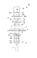
本実施形態に係る顕微鏡装置1は、図1に示されるように、レーザ光源2と、標本Aを収容して培養する培養部3と、該培養部3を搭載して移動させるステージ4と、レーザ光源2からの光を集光して標本Aに照射する第1の集光光学系5と、標本Aを透過した透過光を集光する第2の集光光学系6と、第2の集光光学系6により集光された透過光の一部を遮断するピンホール部材7と、ピンホール部材7を通過した透過光を検出する光検出器8と、これらを取り囲む筐体9と、筐体9に配置された温度センサ10およびヒータ11と、これらを制御する制御部12と、制御部12に接続されたモニタ13とを備えている。
A microscope apparatus 1 according to a first embodiment of the present invention will be described below with reference to the drawings.
As shown in FIG. 1, the microscope apparatus 1 according to the present embodiment includes a
培養部3は、図2に示されるように、培養液Bを貯留し該培養液B内に標本Aを浸漬した状態で収容する培養容器14と、該培養容器14を取り囲む外側容器15とを備えている。培養容器14は外側容器15内において上方に開口されている。外側容器15は、上方に開口する容器本体15aと、該容器本体15aの開口に接触状態に配置されて、容器本体15aに対して水平方向に移動可能に配されつつ開口を閉鎖する蓋体15bとを備えている。蓋体15bは、後述するZステージ4cに固定され,Zステージ4cの作動によって鉛直方向に移動させられるようになっている。
As shown in FIG. 2, the
Zステージ4cには、支柱16が固定され、蓋体15bが支柱16に蝶番17によって揺動可能に固定されている。
蓋体15bの中央部には、第2の集光光学系5の一部を構成する後述する第2対物レンズを貫通させる貫通孔18が設けられている。貫通孔18と第2対物レンズ6aとの間はシール部材19によって鉛直方向に相対移動可能に密封され、容器本体15aと蓋体15bとの間は、シール部材20によって、水平方向に相対移動可能に密封されている。
A
A through-
培養部3の培養容器14内には、培養液Bを循環するためのチューブ21が接続されている。
また、培養部3の外側容器15と培養容器14との間の空間には、蒸気や、CO2を供給するためのチューブ22が接続されている。また、この空間には、該空間内の温度を検出する温度センサ10が設けられている。
A
Further, a
ステージ4は、図2に示されるように、外側容器15を搭載して、水平方向(X方向)に移動させるXステージ4aと、該Xステージ4aをX方向に直交する水平方向(Y方向)に移動させるYステージ4bと、Xステージ4aおよびYステージ4bを鉛直方向(Z方向)に移動させるZステージ4cとを備えている。各X,Y,Zステージ4a,4b,4cには、外側容器の下方に配される位置に開口部23が設けられており、鉛直下方から入射される照明光が開口部23を介して容器本体15aの底面から培養部3の標本Aに照射されるようになっている。
As shown in FIG. 2, the
第1の集光光学系5は、レーザ光を集光する集光レンズ5aと、該集光レンズ5aにより集光されたレーザ光を互いに直交する偏光面を有する偏光成分に分割する第1の微分干渉素子5bと、該第1の微分干渉素子5bを透過したレーザ光をその上方に配置されている標本A上に集光する第1対物レンズ5cとを備えている。
The first condensing
第2の集光光学系6は、標本Aを透過したレーザ光を集光する第2対物レンズ6aと、該第2対物レンズ6aにより集光された互いに直交する偏光面を有する偏光成分を単一偏光面を有するレーザ光に統合する第2の微分干渉素子6bと、該第2の微分干渉素子6bを透過した統合された偏光以外のレーザ光を遮断する偏光素子6cと、該偏光素子6cを透過したレーザ光を集光する集光レンズ6dとを備えている。
本実施形態において、第2対物レンズ6aは、図2に示されるように、液浸レンズにより構成され、培養容器14内の培養液Bに浸漬された状態で使用されるようになっている。
The second condensing
In the present embodiment, as shown in FIG. 2, the second
ピンホール部材7は、標本Aにおけるレーザ光の集光位置と光学的に共役な位置に配置され、集光点を通ったレーザ光のみが通過でき、集光点以外からのレーザ光は遮断されるようになっている。
光検出器8は、例えば、光電子増倍管である。
The
The photodetector 8 is, for example, a photomultiplier tube.
筐体9は、図1に示されるように、ステージ4を挟んで上下に配置されたレンズ等の光学素子をそれぞれ取り囲んで外部に対して閉塞している。これにより、ステージ4を挟んだ上下の空間24,25が、該空間24.25内に外来光が入射しないように遮断され、特に、光検出器8やピンホール部材7の周囲に外来光が入射しないようになっている。
As shown in FIG. 1, the
温度センサ10は、上述したように培養容器14と外部容器15との間の空間、および筐体9内のステージ4の上部空間24および下部空間25の温度をそれぞれ検出するようにそれぞれ配置されている。
ヒータ11も、筐体9内の上部空間24、下部空間25および培養部3の近傍にそれぞれ配置され、それぞれの部位を独立して加温することができるようになっている。
As described above, the
The
制御部12は、温度センサ10により検出された温度情報を受け取って、筐体9内の上部空間24、下部空間25および培養部3内がそれぞれ所望の温度になるようにヒータ11を制御するようになっている。
また、制御部12は、ステージ4を駆動して培養部3を移動させるとともに、各位置において光検出器8において検出された透過光の強度をステージ4の位置情報と対応づけて記憶するようになっている。そして、制御部12は、記憶している透過光の強度をステージ4の位置情報に基づいて並べることにより、標本Aの2次元的な微分干渉画像を生成するようになっている。
モニタ13は、制御部12により生成された透過光の微分干渉画像を表示するようになっている。
The
The
The
このように構成された本実施形態に係る顕微鏡装置1の作用について、以下に説明する。
本実施形態に係る顕微鏡装置1を用いて標本Aの観察を行うには、チューブ21を介して培養部3の培養容器14内に貯留した培養液Bを循環させながら、チューブ22を介して供給した蒸気やCO2により、培養容器14内の湿度およびCO2濃度等の培養条件を一定に維持しつつ、温度センサ10により検出した培養部3内の温度に基づいて、該温度が所定の温度、例えば、37℃となるように、制御部12がヒータ11を制御する。
また、制御部12は、筐体9内の上部空間24および下部空間25内部の温度センサ10により検出した筐体9内の温度に基づいて、該温度が所定の温度になるように、ヒータ11を制御する。
The operation of the microscope apparatus 1 according to the present embodiment configured as described above will be described below.
In order to observe the specimen A using the microscope apparatus 1 according to the present embodiment, the culture solution B stored in the
In addition, the
そして、筐体9内および培養部3内の温度が恒温化された状態で、制御部12が、ステージ4を駆動して標本Aを所望の位置に配置する。この状態で、レーザ光源2から発せられたレーザ光を第1の集光光学系5によって標本A上に集光し、標本Aを透過した透過光を第2の集光光学系6によって集光し、ピンホール部材7を通過した透過光のみを光検出器8によって検出する。制御部12は、検出された透過光の強度をステージ4の位置情報と対応づけて記憶し、ステージ4を次の位置まで移動させ、上記動作を繰り返す。
And the
これにより、標本A上の所望の領域にレーザ光が通過させられて、標本Aの透過光画像を取得することができる。第1の集光光学系5および第2の集光光学系6には第1,第2の微分干渉素子5b,6bおよび偏光素子6cが設けられているので、透過光画像としては、微分干渉画像が取得される。取得された微分干渉画像はモニタ13に表示される。
Thereby, the laser beam is passed through a desired region on the specimen A, and a transmitted light image of the specimen A can be acquired. Since the first condensing
この場合において、本実施形態に係る顕微鏡装置1によれば、各光学素子が筐体9によって取り囲まれているので、外来光が遮断され、取得される透過レーザ光画像に発生するノイズを低減して鮮明な観察を行うことができるという利点がある。
さらに、筐体9内の各部の温度は温度センサ10により検出された温度に基づいてヒータ11を制御することにより恒温化されているので、各光学素子に温度差による歪みが発生するのを防止することができ、長時間観察中に観察位置がずれてしまう不都合の発生を未然に防止することができるという利点もある。
In this case, according to the microscope apparatus 1 according to the present embodiment, since each optical element is surrounded by the
Furthermore, since the temperature of each part in the
また、本実施形態においては、第2の集光光学系6を構成する第2対物レンズ6aが液浸レンズによって構成され、培養液B内に浸漬された状態で使用されるので、培養液Bの液面位置が変動しても標本A上におけるレーザ光の集光点とピンホール部材7との光学的に共役な位置関係が崩れることがなく、常に鮮明な透過光画像を取得することができる。
また、本実施形態においては、透過光画像として微分干渉画像を取得するので、透明な標本Aであっても、その形態を鮮明に観察することができる。
In the present embodiment, the second
Moreover, in this embodiment, since a differential interference image is acquired as a transmitted light image, even if it is the transparent sample A, the form can be observed clearly.
この場合において、第2対物レンズ6aの焦点位置を合わせるために、Zステージ4cを移動させると、Zステージ4cとともに、容器本体15aおよび蓋体15bが同時に上下に移動する。蓋体15の貫通孔18と第2対物レンズ6aとの間はシール部材19によって鉛直方向に摺動可能に設けられているので、Zステージ4cを移動させて蓋体15が第2対物レンズ6aに対して鉛直方向に移動しても、両者間の密封状態が維持される。
In this case, when the
また、標本Aに対するレーザ光の集光点を変更するために、Xステージ4aおよびYステージ4bを移動させると、Xステージ4aに搭載されている容器本体15aも水平方向に移動させられる。容器本体15aの上端と蓋体15bの下面との間もシール部材20によって水平方向に摺動可能に設けられているので、X,Yステージ4a,4bを移動させて容器本体15aが第2対物レンズ6aに対して水平方向に移動しても、蓋体15bと容器本体15aとの間の密封状態が維持される。
これにより、外側容器15a内が密封された状態に維持され、培養環境が一定に保持されて、生細胞等の標本Aの長時間にわたる観察においても、標本Aを健全な状態に維持することができる。
Further, when the
Thereby, the inside of the
なお、本実施形態においては、第2対物レンズ6aを液浸レンズとして、培養液B内に常に浸漬した状態を維持することとした。しかし、液浸レンズであっても培養液Bの液面から離れて上方に配された状態で観察する場合や、液浸レンズではない場合には、培養液Bの液面が変動すると、ピンホール部材7への集光位置がずれてしまい、レーザ光の標本Aにおける集光点を通過する透過光を検出することができない。そのような場合には、液面の位置を検出する液面センサ(図示略)を設け、液面センサにより検出された液面の位置に基づいて、制御部12がピンホール部材7あるいは第2対物レンズ6aを鉛直方向に移動させる位置調節機構(図示略)を有することにすればよい。
In the present embodiment, the second
次に、本発明の第2の実施形態に係る顕微鏡装置30について、図面を参照して説明する。
本実施形態の説明において、上述した第1の実施形態に係る顕微鏡装置1と構成を共通とする箇所については、同一符号を付して説明を省略する。
Next, a
In the description of the present embodiment, portions having the same configuration as those of the microscope apparatus 1 according to the first embodiment described above are denoted by the same reference numerals and description thereof is omitted.
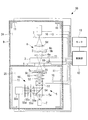
本実施形態に係る顕微鏡装置30は、図3に示されるように、第1の集光光学系31に、レーザ光源2からのレーザ光を集光する集光レンズ31aと、該集光レンズ31aによって集光されたレーザ光を複数の光束に分割するマイクロレンズアレイ31bとを備えている。また、ピンホール部材32としては、複数の光束が標本A上においてそれぞれの集光点に集光することにより、各集光点を通過したレーザ光を通過させるために、各集光点と光学的に共役な位置関係に配置される複数のピンホール32aを備えたものが採用されている。また、光検出器33としては、各ピンホール32aを通過した透過光をそれぞれ独立に検出する複数の受光部33aを有するマルチアノード光電子増倍管あるいはCCDが採用されている。
As shown in FIG. 3, the
このように構成された本実施形態に係る顕微鏡装置30によれば、レーザ光源2から射出されたレーザ光は、マイクロレンズアレイ31bを通過することにより複数の光束に分割され、第1の集光光学系31によって、図4に示されるように、標本A上の複数箇所に集光される。図中、斜線部が集光点を示している。
According to the
そして、X,Yステージ4a,4bを駆動して標本Aを水平方向に移動させることにより、図4に矢印で示されるように、集光点によって視野内の所定範囲を埋めるように標本A上における集光点を移動させ、各位置を透過した透過光を検出して透過光画像を得ることができる。
Then, by driving the X and
すなわち、本実施形態に係る顕微鏡装置30によれば、第1の実施形態に係る顕微鏡装置1と比較して、複数の集光点を透過した複数の透過光を同時に検出するので、より迅速に画像を取得することができる。特に、生細胞のように動く標本Aを観察する場合に、ブレを低減しつつ観察することができ、効果的である。
また、本実施形態においても、全ての光学素子が筐体9によって囲まれているので、外来光を遮断して鮮明な画像を得ることができるとともに、筐体9内の温度を管理することによって温度差による光学素子の変形を防止して長時間観察においても位置ズレが生じないようにすることができる。
That is, according to the
Also in this embodiment, since all the optical elements are surrounded by the
なお、本実施形態においては、各ピンホール32aを通過したレーザ光を別個の受光部33aによって独立に検出することとしたが、これに代えて、隣接する複数の受光部33a(あるいは画素)によって各ピンホール32aを通過したレーザ光を検出することにしてもよい。この場合には、各受光部32aにより検出されたレーザ光の強度を加算して1つの集光点からの情報として処理すればよい。
In the present embodiment, the laser light that has passed through each pinhole 32a is detected independently by a separate
また、標本Aを異なる倍率で観察するために、第1対物レンズ5cおよび第2対物レンズ6aが、レボルバ等(図示略)によって複数の倍率のものを切替可能に用意されていてもよい。この場合には、制御部12が、第1対物レンズ5cおよび第2対物レンズ6aの両方の倍率が同一倍率となるように切り替えることにすればよい。あるいは、手動で同一倍率に切り替えることにしてもよい。
Further, in order to observe the specimen A at different magnifications, the first
あるいは、第1対物レンズ5cのみ切替可能にして、ピンホール部材32として、ディジタルマイクロミラーデバイス(DMD)や液晶シャッタ等の反射または透過パターンを変更可能な空間変調器を採用してもよい。このようにすることで、第1対物レンズ5cの倍率を切り替えることによりレーザ光の集光点が変動しても、それに合わせるように空間変調器の反射または透過パターンを変更することで、ピンホール部材32と標本A上の集光点との光学的に共役な位置関係を維持することができる。
Alternatively, a spatial modulator capable of changing the reflection or transmission pattern, such as a digital micromirror device (DMD) or a liquid crystal shutter, may be employed as the
次に、本発明の第3の実施形態に係る顕微鏡装置40について、図面を参照して説明する。
本実施形態の説明において、上述した第2の実施形態に係る顕微鏡装置30と構成を共通とする箇所には同一符号を付して説明を省略する。
Next, a
In the description of the present embodiment, portions having the same configuration as those of the
本実施形態に係る顕微鏡装置40は、図5および図6に示されるように、第2の実施形態に係る顕微鏡装置30におけるマイクロレンズアレイ31bに代えて、シリンドリカルレンズ41aおよびDMDや液晶シャッタ等の第1の空間変調器41bを使用し、ピンホール部材32に代えて、第2の空間変調器42aおよびシリンドリカルレンズ42bを採用している。
また、光検出器43としては、一列に並んだ複数の受光部43aを有するラインCCDあるいはマルチアノード光電子増倍管を採用している。
As shown in FIGS. 5 and 6, the
As the photodetector 43, a line CCD having a plurality of light receiving portions 43a arranged in a line or a multi-anode photomultiplier tube is employed.
第1の集光光学系31におけるシリンドリカルレンズ41aは、レーザ光源2から発せられたレーザ光をライン状に集光して第1の空間変調器41bに入射させるようになっている。また、第1の空間変調器41bは、その透過または反射パターンによって、ライン状に集光されたレーザ光を部分的に透過または反射することにより複数本の光束を生成するようになっている。
The
一方、第2の集光光学系6における第2の空間変調器42aは、標本A上における光束の集光点と光学的に共役な位置に入射する光のみを反射または透過するように反射または透過パターンが設定されている。また、シリンドリカルレンズ42bは、第2の空間変調器42aにより反射または透過された透過光を集光して、一列に並ぶ光検出器33の複数の受光部33aにそれぞれ入射させるようになっている。
On the other hand, the second
このように構成された本実施形態に係る顕微鏡装置40によれば、レーザ光源2から射出されたレーザ光は、シリンドリカルレンズ41aおよび第1の空間変調器41bを通過することにより複数の光束に分割され、第1の集光光学系31によって、図7に示されるように、標本A上の複数箇所を通過させられる。図中、斜線部がレーザ光の通過位置を示している。
According to the
そして、X,Yステージ4a,4bを駆動して標本Aを水平方向に移動させることにより、図7に矢印で示されるように、集光点によって視野内の所定範囲を埋めるように標本A上におけるレーザ光の通過位置を移動させ、各位置を透過した透過光を検出して透過レーザ光画像を得ることができる。
Then, by driving the X and
このようにすることで、第2の実施形態に係る顕微鏡装置30と同様に、複数箇所の透過光を同時に検出するので、より迅速に画像を取得することができる。特に、生細胞のように動く標本を観察する場合に、ブレを低減しつつ観察することができ、効果的である。
By doing in this way, similarly to the
また、本実施形態においても、全ての光学素子が筐体9によって囲まれているので、外来光を遮断して鮮明な画像を得ることができるとともに、筐体9内の温度を管理することによって温度差による光学素子の変形を防止して長時間観察においても位置ズレが生じないようにすることができる。
Also in this embodiment, since all the optical elements are surrounded by the
次に、本発明の第4の実施形態に係る顕微鏡装置50について、図面を参照して説明する。
本実施形態の説明において、上述した第1の実施形態に係る顕微鏡装置1と構成を共通とする箇所には同一符号を付して説明を省略する。
Next, a
In the description of the present embodiment, portions having the same configuration as those of the microscope apparatus 1 according to the first embodiment described above are denoted by the same reference numerals and description thereof is omitted.
本実施形態に係る顕微鏡装置50は、図8に示されるように、集光レンズ5aによって集光されたレーザ光を2次元的に走査するスキャナ51と、該スキャナ51により走査されたレーザ光を集光する瞳投影レンズ52および結像レンズ53と、標本Aにおいて発生し、レーザ光源2側に戻る蛍光をスキャナ51と集光レンズ5aとの間でレーザ光の光路から分岐するダイクロイックミラー54と、蛍光検出光学系55とをさらに備えている。
As shown in FIG. 8, the
スキャナ51は、例えば、異なる軸線回りに揺動させられる2枚のガルバノミラー(図示略)を対向配置してなる近接ガルバノミラーである。2枚のガルバノミラーを同期させつつ揺動させることにより、レーザ光を標本A上において2次元的に走査させることができるようになっている。一方、ガルバノミラーの揺動を停止させることにより、レーザ光を静止させ、ステージ4を移動させることによっても、レーザ光を標本A上において2次元的に走査させることができるようになっている。
The
蛍光検出光学系55は、ダイクロイックミラーによって分岐された蛍光を集光する共焦点レンズ55aと、該共焦点レンズ55aの焦点位置に配置され、焦点位置を通過する蛍光のみを通過させる共焦点ピンホール55bと、該共焦点ピンホール55bを通過した蛍光を集光する集光レンズ55cと、蛍光に含まれるレーザ光を遮断するバリアフィルタ55dと、該バリアフィルタ55dを透過した蛍光を検出する光電子増倍管からなる光検出器55eとを備えている。
本実施形態においては、これらの光学素子も全て筐体9内に配置されて、温度管理されている。
The fluorescence detection
In the present embodiment, all of these optical elements are also arranged in the
このように構成された本実施形態に係る顕微鏡装置50によれば、スキャナ51を停止した状態でステージ4を移動させて透過光の透過共焦点観察を行い、ステージ4を停止した状態でスキャナ51を駆動して、標本Aにおいて発生した蛍光の落射共焦点観察を行うことができる。
本実施形態においても、全ての光学素子が筐体9によって囲まれているので、外来光を遮断して鮮明な透過光画像および蛍光画像を得ることができるとともに、筐体9内の温度を管理することによって温度差による光学素子の変形を防止して長時間観察においても位置ズレが生じないようにすることができる。
According to the
Also in the present embodiment, since all the optical elements are surrounded by the
蛍光画像はスキャナ51を使用しているのでフレームレートが高い。スキャナ51を停止した状態でステージ4を移動させて透過光の透過共焦点観察と、標本Aにおいて発生した蛍光を同時に取得することにしてもよい。この場合には、透過画像と蛍光画像とが同時刻に取得されているので、細胞の形態変化を透過画像と蛍光画像で比較するような観察方法に適している。
Since the fluorescent image uses the
なお、上記各実施形態においては、レーザ光源2も筐体9内に収容することとして説明したが、レーザ光源2は筐体9外に配置することにしてもよい。
また、ステージを光学系に対してその光軸に直交する方向に移動させることとしたが、これに代えて、ステージを固定し、光学系全体を移動させることにしてもよい。
In each of the above embodiments, the
Further, although the stage is moved in the direction perpendicular to the optical axis with respect to the optical system, instead of this, the stage may be fixed and the entire optical system may be moved.
また、上記各実施形態においては、微分干渉画像を取得するために第1の微分干渉素子5b、第2の微分干渉素子6b、偏光素子6cを備えることとしたが、これに代えて、第2の集光光学系6としては、位相リング(図示略)を、第1の集光光学系5としては、位相膜(図示略)を有する位相差観察用の集光光学系を採用してもよい。
In each of the above embodiments, the first
A 標本
B 培養液
1,30,40,50 顕微鏡装置
2 光源
3 培養部
4 ステージ(移動機構)
5,31 第1の集光光学系
5b 第1の微分干渉素子
6 第2の集光光学系
6b 第2の微分干渉素子
6c 偏光素子
7,32 ピンホール部材(透過用ピンホール)
8 光検出器(透過用光検出器)
9 筐体
10 温度センサ(温度制御部)
11 ヒータ(温度制御部)
31b マイクロレンズアレイ(光束分割部)
32a ピンホール(透過用ピンホール)
33a 受光部(透過用光検出器)
41a シリンドリカルレンズ(変換光学系)
41b 第1の空間変調器
42a 第2の空間変調器(透過用ピンホール)
51 スキャナ(走査部)
54 ダイクロイックミラー(蛍光分岐部)
55b 共焦点ピンホール(落射用ピンホール)
55e 光検出器(落射用光検出器)
A Specimen
5, 31 1st condensing
8 Photodetector (Photodetector for transmission)
9
11 Heater (Temperature controller)
31b Micro lens array (light beam splitting part)
32a pinhole (transmission pinhole)
33a Light-receiving part (light detector for transmission)
41a Cylindrical lens (conversion optical system)
41b First
51 Scanner (scanning unit)
54 Dichroic mirror (fluorescence branch)
55b Confocal pinhole
55e Photodetector (photodetector for incident light)
Claims (8)
該培養部を保持するステージと、
光源からの照明光を前記標本に集光する第1の集光光学系と、
該第1の集光光学系により前記標本に照射され前記標本を透過した透過光を集光する第2の集光光学系と、
前記標本における照明光の集光位置と光学的に共役な位置に配置され、前記第2の集光光学系により集光された透過光の一部を遮断する透過用ピンホールと、
該透過用ピンホールを通過した透過光を検出する透過用光検出器と、
これら第1および第2の集光光学系、前記透過用ピンホールおよび前記透過用光検出器と前記ステージとを相対的に移動させる移動機構と、
前記培養部、前記ステージ、前記第1の集光光学系、前記第2の集光光学系、前記透過用ピンホール、前記透過用光検出器および前記移動機構を取り囲み外光を遮断する筐体と、
該筐体内の温度を制御する温度制御部とを備え、
前記培養部が培養液を貯留し、
前記第2の集光光学系が前記培養液の液面から離れた位置に配置され、
前記培養液の液面を検出する液面検出部と、該液面検出部により検出された前記培養液の液面位置に基づいて前記透過用ピンホールまたは前記第2の集光光学系の光軸に沿う方向の位置を調節する位置調節機構とを備える顕微鏡装置。 A culture part for accommodating the specimen and culturing while maintaining constant temperature and humidity; and
A stage for holding the culture part;
A first condensing optical system for condensing illumination light from a light source on the specimen;
A second condensing optical system for condensing transmitted light that has been irradiated onto the specimen by the first condensing optical system and transmitted through the specimen;
A transmission pinhole that is disposed at a position optically conjugate with the light collection position of the illumination light in the sample and blocks a part of the transmitted light collected by the second light collection optical system;
A transmission photodetector that detects the transmitted light that has passed through the transmission pinhole;
A moving mechanism for relatively moving the first and second condensing optical systems, the transmission pinhole and the transmission photodetector, and the stage;
A casing that surrounds the culture unit, the stage, the first condensing optical system, the second condensing optical system, the transmission pinhole, the transmission photodetector, and the moving mechanism and blocks outside light When,
A temperature control unit for controlling the temperature in the housing,
The culture unit stores a culture solution,
The second condensing optical system is disposed at a position away from the liquid surface of the culture solution;
A liquid level detector for detecting the liquid level of the culture medium, and the light from the transmission pinhole or the second condensing optical system based on the liquid level position of the culture liquid detected by the liquid level detector A microscope apparatus comprising: a position adjusting mechanism that adjusts a position in a direction along the axis.
該走査部により照明光が前記標本上で走査されることにより、該標本において発生して前記第1の集光光学系により集光され、前記走査部を介して戻る蛍光を分岐する蛍光分岐部と、
前記標本と光学的に共役な位置に配置され、前記蛍光分岐部により分岐された蛍光の一部を遮断する落射用ピンホールと、
該落射用ピンホールを通過した蛍光を検出する落射用光検出器とを備え、
前記筐体が、前記走査部、前記蛍光分岐部、前記落射用ピンホールおよび前記落射用光検出器をも取り囲んでいる請求項1に記載の顕微鏡装置。 A scanning unit disposed between the light source and the first condensing optical system and scanning illumination light from the light source;
A fluorescence branching unit that divides the fluorescence generated on the sample, collected by the first light collecting optical system, and returned through the scanning unit by scanning the illumination light on the sample by the scanning unit. When,
An epi-illuminating pinhole that is disposed at a position optically conjugate with the sample and blocks a part of the fluorescence branched by the fluorescence branching portion;
An incident light detector for detecting fluorescence that has passed through the incident pinhole,
The microscope apparatus according to claim 1, wherein the casing also surrounds the scanning unit, the fluorescence branching unit, the incident pinhole, and the incident light detector.
該レーザ光源から射出されたレーザ光を、前記標本への入射前に、互いに直交する偏光面を有する偏光成分に分割する第1の微分干渉素子と、
前記標本を通過した互いに直交する偏光面を有する偏光成分を単一偏光面を有する偏光に統合する第2の微分干渉素子と、
該第2の微分干渉素子により統合された偏光以外の光を遮断する偏光素子とを備え、
前記筐体が、前記第1、第2の微分干渉素子および前記偏光素子をも取り囲んでいる請求項1又は請求項2に記載の顕微鏡装置。 The light source is a laser light source that emits laser light;
A first differential interference element that divides laser light emitted from the laser light source into polarization components having polarization planes orthogonal to each other before being incident on the specimen;
A second differential interference element that integrates polarization components having orthogonal polarization planes that have passed through the sample into polarized light having a single polarization plane;
A polarizing element that blocks light other than polarized light integrated by the second differential interference element,
The microscope apparatus according to claim 1 , wherein the housing surrounds the first and second differential interference elements and the polarizing element.
前記透過用ピンホールが、前記光束分割部により分割された複数の光束の前記標本上における集光位置とそれぞれ共役な位置に複数配置され、
前記透過用光検出器が、複数の前記透過用ピンホールを通過した複数の照明光をそれぞれ検出するように複数設けられている請求項1から請求項4のいずれかに記載の顕微鏡装置。 A light beam splitting unit that splits the illumination light from the light source into a plurality of light beams;
A plurality of the transmission pinholes are arranged at positions conjugate to the light collection positions on the sample of the plurality of light beams divided by the light beam dividing unit,
The microscope apparatus according to any one of claims 1 to 4 , wherein a plurality of the light detectors for transmission are provided so as to detect a plurality of illumination lights that have passed through the plurality of pinholes for transmission.
前記透過用ピンホールが、反射または透過パターンを変更可能な空間変調器により構成され、
前記第1の集光光学系の倍率が切り替えられたときには、前記透過用ピンホールの反射または透過パターンを切り替える請求項5に記載の顕微鏡装置。 The first condensing optical system is provided so that a plurality of sets can be switched at different magnifications,
The transmission pinhole is constituted by a spatial modulator capable of changing a reflection or transmission pattern,
The microscope apparatus according to claim 5, wherein when the magnification of the first condensing optical system is switched, the reflection or transmission pattern of the transmission pinhole is switched.
該変換光学系により変換されたラインビームの一部を選択的に反射または透過させるように反射または透過パターンを変更可能に構成され、複数の光束を生成する第1の空間変調器と、
前記透過用ピンホールが、反射または透過パターンを変更可能に構成され、反射または透過位置が前記第1の空間変調器と光学的に共役な位置関係を保つように駆動される第2の空間変調器により構成され、
前記透過用光検出器が、複数の前記透過用ピンホールを通過した複数の照明光をそれぞれ検出するように複数設けられている請求項1に記載の顕微鏡装置。 A conversion optical system that converts illumination light from the light source into a line beam;
A first spatial light modulator configured to change a reflection or transmission pattern so as to selectively reflect or transmit a part of the line beam converted by the conversion optical system, and to generate a plurality of light beams;
The second spatial modulation is configured such that the transmission pinhole is configured to change a reflection or transmission pattern, and the reflection or transmission position is driven to maintain an optically conjugate positional relationship with the first spatial modulator. Composed of
The microscope apparatus according to claim 1, wherein a plurality of the light detectors for transmission are provided so as to detect a plurality of illumination lights that have passed through the plurality of pinholes for transmission.
Priority Applications (2)
| Application Number | Priority Date | Filing Date | Title |
|---|---|---|---|
| JP2009275584A JP5638793B2 (en) | 2009-12-03 | 2009-12-03 | Microscope equipment |
| US12/955,428 US8730574B2 (en) | 2009-12-03 | 2010-11-29 | Microscope system |
Applications Claiming Priority (1)
| Application Number | Priority Date | Filing Date | Title |
|---|---|---|---|
| JP2009275584A JP5638793B2 (en) | 2009-12-03 | 2009-12-03 | Microscope equipment |
Publications (3)
| Publication Number | Publication Date |
|---|---|
| JP2011118162A JP2011118162A (en) | 2011-06-16 |
| JP2011118162A5 JP2011118162A5 (en) | 2013-01-10 |
| JP5638793B2 true JP5638793B2 (en) | 2014-12-10 |
Family
ID=44081780
Family Applications (1)
| Application Number | Title | Priority Date | Filing Date |
|---|---|---|---|
| JP2009275584A Expired - Fee Related JP5638793B2 (en) | 2009-12-03 | 2009-12-03 | Microscope equipment |
Country Status (2)
| Country | Link |
|---|---|
| US (1) | US8730574B2 (en) |
| JP (1) | JP5638793B2 (en) |
Families Citing this family (14)
| Publication number | Priority date | Publication date | Assignee | Title |
|---|---|---|---|---|
| CN102792151B (en) | 2010-03-23 | 2015-11-25 | 加州理工学院 | For the super resolution optofluidic microscope of 2D and 3D imaging |
| US9426429B2 (en) | 2010-10-26 | 2016-08-23 | California Institute Of Technology | Scanning projective lensless microscope system |
| US9569664B2 (en) * | 2010-10-26 | 2017-02-14 | California Institute Of Technology | Methods for rapid distinction between debris and growing cells |
| US9643184B2 (en) | 2010-10-26 | 2017-05-09 | California Institute Of Technology | e-Petri dishes, devices, and systems having a light detector for sampling a sequence of sub-pixel shifted projection images |
| CN103534627A (en) | 2011-03-03 | 2014-01-22 | 加州理工学院 | Light guided pixel |
| JP5999121B2 (en) * | 2014-02-17 | 2016-09-28 | 横河電機株式会社 | Confocal light scanner |
| JP6270560B2 (en) * | 2014-03-14 | 2018-01-31 | オリンパス株式会社 | Culture microscope |
| CN112697792A (en) * | 2014-12-26 | 2021-04-23 | 希森美康株式会社 | Cell imaging device, cell imaging method, and sample cell |
| JP6539052B2 (en) * | 2015-01-20 | 2019-07-03 | 浜松ホトニクス株式会社 | Image acquisition apparatus and image acquisition method |
| JP6300739B2 (en) | 2015-01-20 | 2018-03-28 | 浜松ホトニクス株式会社 | Image acquisition apparatus and image acquisition method |
| US10394008B2 (en) * | 2016-10-19 | 2019-08-27 | Cornell University | Hyperspectral multiphoton microscope for biomedical applications |
| JP2018102228A (en) * | 2016-12-27 | 2018-07-05 | オリンパス株式会社 | Observation device |
| US10508971B2 (en) * | 2017-09-07 | 2019-12-17 | Taiwan Semiconductor Manufacturing Co., Ltd. | Optical test system and method for determining size of gap between two substrates of optical element |
| US20220026696A1 (en) * | 2018-12-21 | 2022-01-27 | Lavision Biotec Gmbh | Light sheet microscope with turreted lenses |
Family Cites Families (22)
| Publication number | Priority date | Publication date | Assignee | Title |
|---|---|---|---|---|
| JPS59172617A (en) * | 1983-03-22 | 1984-09-29 | Olympus Optical Co Ltd | Microscope equipped with automatic control type optical lighting system |
| JPH0391709A (en) * | 1989-09-05 | 1991-04-17 | Nikon Corp | Scanning differential interference microscope |
| JPH08233544A (en) * | 1995-02-28 | 1996-09-13 | Komatsu Ltd | Confocal optical apparatus |
| JPH1090604A (en) * | 1996-09-10 | 1998-04-10 | Olympus Optical Co Ltd | Differential interference microscope |
| JP2000035540A (en) * | 1998-07-16 | 2000-02-02 | Nikon Corp | Differential interference microscope |
| ES2520140T3 (en) * | 1999-02-17 | 2014-11-11 | Lucid, Inc. | Tissue sample carrier |
| JP3988399B2 (en) * | 2001-03-09 | 2007-10-10 | スズキ株式会社 | Chromosome specimen expansion device |
| WO2004109361A1 (en) * | 2003-06-02 | 2004-12-16 | Nikon Corporation | Micrroscope device |
| JP4457670B2 (en) * | 2004-01-15 | 2010-04-28 | 株式会社ニコン | microscope |
| JP4819383B2 (en) * | 2004-03-26 | 2011-11-24 | オリンパス株式会社 | Optical microscope and optical observation method |
| JP2006003653A (en) * | 2004-06-17 | 2006-01-05 | Olympus Corp | Biological sample observating system |
| FI116946B (en) * | 2004-07-09 | 2006-04-13 | Chip Man Technologies Oy | Apparatus for imaging cells |
| JP4658565B2 (en) * | 2004-10-28 | 2011-03-23 | オリンパス株式会社 | Microscope and microscope heating method |
| JP4728632B2 (en) * | 2004-12-03 | 2011-07-20 | 株式会社キーエンス | Inverted microscope |
| JP2006235420A (en) * | 2005-02-28 | 2006-09-07 | Yokogawa Electric Corp | Confocal microscope |
| JP4889375B2 (en) * | 2006-05-25 | 2012-03-07 | オリンパス株式会社 | Confocal microscope and multi-photon excitation microscope |
| JP5307539B2 (en) * | 2006-05-31 | 2013-10-02 | オリンパス株式会社 | Biological sample imaging method and biological sample imaging apparatus |
| JP4669995B2 (en) | 2006-08-02 | 2011-04-13 | ナノフォトン株式会社 | Optical microscope and observation method |
| US7443483B2 (en) * | 2006-08-11 | 2008-10-28 | Entegris, Inc. | Systems and methods for fluid flow control in an immersion lithography system |
| JP5047669B2 (en) * | 2007-04-04 | 2012-10-10 | オリンパス株式会社 | Scanning confocal microscope |
| JP4409586B2 (en) * | 2007-06-20 | 2010-02-03 | オリンパス株式会社 | Box-type electric microscope |
| JP4288323B1 (en) * | 2008-09-13 | 2009-07-01 | 独立行政法人科学技術振興機構 | Microscope device and fluorescence observation method using the same |
-
2009
- 2009-12-03 JP JP2009275584A patent/JP5638793B2/en not_active Expired - Fee Related
-
2010
- 2010-11-29 US US12/955,428 patent/US8730574B2/en active Active
Also Published As
| Publication number | Publication date |
|---|---|
| JP2011118162A (en) | 2011-06-16 |
| US8730574B2 (en) | 2014-05-20 |
| US20110134516A1 (en) | 2011-06-09 |
Similar Documents
| Publication | Publication Date | Title |
|---|---|---|
| JP5638793B2 (en) | Microscope equipment | |
| JP6195922B2 (en) | microscope | |
| EP2317363B1 (en) | Microscope connecting unit and microscope system | |
| US7369308B2 (en) | Total internal reflection fluorescence microscope | |
| US8254020B2 (en) | Objective-coupled selective plane illumination microscopy | |
| US8908271B2 (en) | Laser scanning microscope and its operating method | |
| JP5208650B2 (en) | Microscope system | |
| US9122070B2 (en) | Microscope device | |
| US20120200693A1 (en) | Microscope with a sheet of light | |
| EP3293559A1 (en) | Microscope | |
| JP6241858B2 (en) | Confocal microscope | |
| US20100014158A1 (en) | Microscope apparatus and fluorescence cube installed therein | |
| JP2011102970A (en) | Laser scanning microscope | |
| JP6173154B2 (en) | Microscope system | |
| JP2011118264A (en) | Microscope device | |
| US20180314047A1 (en) | Microscope | |
| JP4818634B2 (en) | Scanning fluorescence observation system | |
| JP2018032009A (en) | microscope | |
| JP2015031812A (en) | Method for setting compensation optical element, and microscope | |
| JP2011118265A (en) | Microscope device | |
| JP7193989B2 (en) | microscope equipment | |
| JP4700334B2 (en) | Total reflection fluorescence microscope | |
| JP2017097301A (en) | Control device, microscope device, control method and control program | |
| US20240137637A1 (en) | Image acquisition apparatus, image acquisition method, and medium | |
| JP5558601B2 (en) | Microscope system |
Legal Events
| Date | Code | Title | Description |
|---|---|---|---|
| A521 | Request for written amendment filed |
Free format text: JAPANESE INTERMEDIATE CODE: A523 Effective date: 20121120 |
|
| A621 | Written request for application examination |
Free format text: JAPANESE INTERMEDIATE CODE: A621 Effective date: 20121120 |
|
| A977 | Report on retrieval |
Free format text: JAPANESE INTERMEDIATE CODE: A971007 Effective date: 20131021 |
|
| A131 | Notification of reasons for refusal |
Free format text: JAPANESE INTERMEDIATE CODE: A131 Effective date: 20140107 |
|
| A521 | Request for written amendment filed |
Free format text: JAPANESE INTERMEDIATE CODE: A523 Effective date: 20140220 |
|
| A02 | Decision of refusal |
Free format text: JAPANESE INTERMEDIATE CODE: A02 Effective date: 20140617 |
|
| A521 | Request for written amendment filed |
Free format text: JAPANESE INTERMEDIATE CODE: A523 Effective date: 20140905 |
|
| A911 | Transfer to examiner for re-examination before appeal (zenchi) |
Free format text: JAPANESE INTERMEDIATE CODE: A911 Effective date: 20140912 |
|
| TRDD | Decision of grant or rejection written | ||
| A01 | Written decision to grant a patent or to grant a registration (utility model) |
Free format text: JAPANESE INTERMEDIATE CODE: A01 Effective date: 20141007 |
|
| A61 | First payment of annual fees (during grant procedure) |
Free format text: JAPANESE INTERMEDIATE CODE: A61 Effective date: 20141023 |
|
| R151 | Written notification of patent or utility model registration |
Ref document number: 5638793 Country of ref document: JP Free format text: JAPANESE INTERMEDIATE CODE: R151 |
|
| S531 | Written request for registration of change of domicile |
Free format text: JAPANESE INTERMEDIATE CODE: R313531 |
|
| R350 | Written notification of registration of transfer |
Free format text: JAPANESE INTERMEDIATE CODE: R350 |
|
| R250 | Receipt of annual fees |
Free format text: JAPANESE INTERMEDIATE CODE: R250 |
|
| R250 | Receipt of annual fees |
Free format text: JAPANESE INTERMEDIATE CODE: R250 |
|
| R250 | Receipt of annual fees |
Free format text: JAPANESE INTERMEDIATE CODE: R250 |
|
| LAPS | Cancellation because of no payment of annual fees |