JP5638618B2 - Displaying composite information of parts - Google Patents
Displaying composite information of parts Download PDFInfo
- Publication number
- JP5638618B2 JP5638618B2 JP2012534195A JP2012534195A JP5638618B2 JP 5638618 B2 JP5638618 B2 JP 5638618B2 JP 2012534195 A JP2012534195 A JP 2012534195A JP 2012534195 A JP2012534195 A JP 2012534195A JP 5638618 B2 JP5638618 B2 JP 5638618B2
- Authority
- JP
- Japan
- Prior art keywords
- data
- model
- layers
- formatted
- client application
- Prior art date
- Legal status (The legal status is an assumption and is not a legal conclusion. Google has not performed a legal analysis and makes no representation as to the accuracy of the status listed.)
- Active
Links
Images


Classifications
-
- G—PHYSICS
- G06—COMPUTING; CALCULATING OR COUNTING
- G06T—IMAGE DATA PROCESSING OR GENERATION, IN GENERAL
- G06T19/00—Manipulating 3D models or images for computer graphics
-
- G—PHYSICS
- G06—COMPUTING; CALCULATING OR COUNTING
- G06F—ELECTRIC DIGITAL DATA PROCESSING
- G06F30/00—Computer-aided design [CAD]
- G06F30/10—Geometric CAD
- G06F30/15—Vehicle, aircraft or watercraft design
-
- G—PHYSICS
- G06—COMPUTING; CALCULATING OR COUNTING
- G06F—ELECTRIC DIGITAL DATA PROCESSING
- G06F2111/00—Details relating to CAD techniques
- G06F2111/02—CAD in a network environment, e.g. collaborative CAD or distributed simulation
-
- G—PHYSICS
- G06—COMPUTING; CALCULATING OR COUNTING
- G06F—ELECTRIC DIGITAL DATA PROCESSING
- G06F2113/00—Details relating to the application field
- G06F2113/24—Sheet material
-
- G—PHYSICS
- G06—COMPUTING; CALCULATING OR COUNTING
- G06F—ELECTRIC DIGITAL DATA PROCESSING
- G06F2113/00—Details relating to the application field
- G06F2113/26—Composites
-
- G—PHYSICS
- G06—COMPUTING; CALCULATING OR COUNTING
- G06T—IMAGE DATA PROCESSING OR GENERATION, IN GENERAL
- G06T2219/00—Indexing scheme for manipulating 3D models or images for computer graphics
- G06T2219/008—Cut plane or projection plane definition
-
- Y—GENERAL TAGGING OF NEW TECHNOLOGICAL DEVELOPMENTS; GENERAL TAGGING OF CROSS-SECTIONAL TECHNOLOGIES SPANNING OVER SEVERAL SECTIONS OF THE IPC; TECHNICAL SUBJECTS COVERED BY FORMER USPC CROSS-REFERENCE ART COLLECTIONS [XRACs] AND DIGESTS
- Y02—TECHNOLOGIES OR APPLICATIONS FOR MITIGATION OR ADAPTATION AGAINST CLIMATE CHANGE
- Y02T—CLIMATE CHANGE MITIGATION TECHNOLOGIES RELATED TO TRANSPORTATION
- Y02T50/00—Aeronautics or air transport
- Y02T50/40—Weight reduction
Description
本発明は概して複合パーツに関し、具体的には複合パーツについての情報を取得する方法及び装置に関するものである。さらに具体的には、本発明は複合パーツのプライの積層体のプライについての情報を取得する方法及び装置に関するものである。 The present invention relates generally to composite parts, and more particularly to a method and apparatus for obtaining information about composite parts. More specifically, the present invention relates to a method and apparatus for obtaining information about a ply in a laminate of composite part plies.
航空機は今もその割合が増加している複合材料で設計され製造されている。ある航空機はその主要構造物の50%以上が複合材料からできている。複合材料は航空機の重量を削減するために航空機に使用されている。この重量の削減により、例えば最大積載量及び燃料効率性等の性能特性が向上する。さらに、複合材料により、航空機の様々なパーツの耐用年数が延びる。 Aircraft are still being designed and manufactured with composite materials that are increasing in proportion. Some aircraft have more than 50% of their main structures made of composite materials. Composite materials are used in aircraft to reduce the weight of the aircraft. This weight reduction improves performance characteristics such as maximum loading capacity and fuel efficiency. In addition, the composite material extends the useful life of various parts of the aircraft.
複合材料は強い軽量材料であり、2つ以上の異なる構成部品を組み合わせて作製される。例えば、複合物は繊維及び樹脂を含むことができる。繊維及び樹脂を混合して硬化させて複合材料を形成する。 Composite materials are strong, lightweight materials that are made by combining two or more different components. For example, the composite can include fibers and resins. Fiber and resin are mixed and cured to form a composite material.
さらに、複合材料を使用することによって、航空機のパーツをより少ない部品でより大きい部分を作製し、多数の留め具を除去することができる。例えば、航空機の機体を、一体化したストリンガーで円筒部分に作製することができる。別の例は、航空機のスタビライザーであり、これは統合スティフナーでスパーと、上部及び下部外板を組み込んだ単一部品として作製することができる。 In addition, by using composite materials, aircraft parts can be made larger with fewer parts and multiple fasteners can be removed. For example, an aircraft fuselage can be made into a cylindrical portion with an integrated stringer. Another example is an aircraft stabilizer, which can be made as a single piece that incorporates a spar and upper and lower skins with an integrated stiffener.
複合パーツに不整合が見られる時には、複合パーツの再加工が必要となり得る。航空機の複合パーツの再加工を行う場合、再加工する材料を差し替えるのに例えば複数のプライの識別、各プライの方向性、複合パーツ内の各プライの位置、プライの材料、及び硬化パーツの厚さ等のプライ積層体のデータが必要である。 When inconsistencies are seen in a composite part, it may be necessary to rework the composite part. When reworking aircraft composite parts, to replace the material to be reworked, for example, identifying multiple plies, the orientation of each ply, the location of each ply within the composite part, the material of the ply, and the thickness of the hardened part Data of the ply laminate such as the same is required.
ある場合には、マニュアルに二次元の図が含まれ得る。これらの図面の複合パーツの詳細には、プライ積層体及びパーツの厚さのデータが含まれる。この情報は、各プライの識別、プライの方向性、積層体におけるプライの位置、プライの材料だけでなくパーツ自体の厚さ情報を含む。この種のデータは通常複合パーツの再加工を行うのに使用される。これらの図面を見つけるのは難しい、又は解釈するのが難しい場合がある。また、図面からプライのレイヤについての情報が伝達されない場合がある。この結果、例えばパーツの再加工等の整備により時間がかかり、費用も増加する可能性がある。 In some cases, the manual may include a two-dimensional diagram. The details of the composite parts in these drawings include ply laminate and part thickness data. This information includes identification of each ply, ply orientation, ply position in the stack, thickness information of the part itself as well as the ply material. This type of data is usually used to rework composite parts. These drawings can be difficult to find or difficult to interpret. In addition, information about the ply layer may not be transmitted from the drawing. As a result, for example, maintenance such as reworking of parts takes time, and the cost may increase.
したがって、上述した少なくとも幾つかの課題だけでなく、潜在的なその他の課題を考慮した方法及び装置を有することが有利である。 Thus, it would be advantageous to have a method and apparatus that takes into account not only at least some of the issues discussed above, but also other potential issues.
ある有利な実施形態では、パーツのモデルを処理する方法が存在する。パーツ上の複数の位置についての情報に対するクライアント・アプリケーションからの要求の受信に応答して、パーツモデルにおける複数の位置を識別する。パーツモデルにおける複数の位置のそれぞれにおいて切断面を作成し、複数の切断面を形成する。複数の切断面のそれぞれの複数のレイヤについてのデータを取得する。複数の切断面を持つモデルを変更して、クライアント・アプリケーションによって使用されるフォーマットを有するフォーマット済みのモデルを形成し、フォーマット済みのモデルを表示する。フォーマット済みのモデルの複数の切断面それぞれの複数のレイヤを、複数の切断面それぞれにおける複数のレイヤについてのデータと関連付けして、ファーマット済みのモデルとデータの間の関連性を形成する。フォーマット済みのモデル及び複数のレイヤについてのデータをクライアント・アプリケーションに応答して返す。 In one advantageous embodiment, there is a method for processing a model of a part. In response to receiving a request from the client application for information about multiple locations on the part, the multiple locations in the part model are identified. A cut surface is created at each of a plurality of positions in the part model to form a plurality of cut surfaces. Data on each of the plurality of layers of the plurality of cut surfaces is acquired. Modify the model with multiple cut planes to form a formatted model having a format used by the client application and display the formatted model. The layers of each of the plurality of cut surfaces of the formatted model are associated with data for the plurality of layers at each of the plurality of cut surfaces to form a relationship between the formatted model and the data. Returns data about the formatted model and multiple layers in response to the client application.
別の有利な実施形態では、装置はバス、バスに接続されたメモリ、メモリに記憶されたプログラムコード、及びプログラムコードを実行するプロセッサ装置を含む。プロセッサ装置はプログラムコードを実行して、パーツ上の複数の位置についての情報に対するクライアント・アプリケーションからの要求の受信に応答して、パーツモデルにおける複数の位置を識別する。プロセッサ装置はプログラムコードを実行して、パーツモデルにおける複数の位置のそれぞれにおいて切断面を作成し、複数の切断面を形成する。プロセッサ装置はプログラムコードを実行して、複数の切断面のそれぞれの複数のレイヤについてのデータを取得する。プロセッサ装置はプログラムコードを実行して、複数の切断面を持つモデルを変更し、クライアント・アプリケーションによって使用されるフォーマットを有するフォーマット済みのモデルを形成してフォーマット済みのモデルを表示する。プロセッサ装置はプログラムコードを実行して、フォーマット済みのモデルの複数の切断面それぞれの複数のレイヤを、複数の切断面それぞれにおける複数のレイヤについてのデータと関連づけて、フォーマット済みのモデルとデータとの関連性を形成する。プロセッサ装置はまたプログラムコードを実行して、クライアント・アプリケーションに応答してフォーマット済みのモデル及び複数のレイヤについてのデータを返す。 In another advantageous embodiment, the apparatus includes a bus, a memory connected to the bus, program code stored in the memory, and a processor device that executes the program code. The processor device executes the program code to identify a plurality of positions in the part model in response to receiving a request from the client application for information about the plurality of positions on the part. The processor device executes the program code, creates a cut surface at each of a plurality of positions in the part model, and forms a plurality of cut surfaces. The processor device executes the program code and obtains data for each of the plurality of layers of the plurality of cut surfaces. The processor device executes the program code to change the model having a plurality of cut planes, forming a formatted model having a format used by the client application and displaying the formatted model. The processor unit executes the program code to associate the plurality of layers of each of the plurality of cut surfaces of the formatted model with the data for the plurality of layers in each of the plurality of cut surfaces, and to Form a relationship. The processor device also executes program code to return data about the formatted model and layers in response to the client application.
さらに別の有利な実施形態では、パーツのモデルを処理するコンピュータプログラム製品が存在する。コンピュータプログラム製品はコンピュータに記録可能な記憶媒体と、コンピュータに記録可能な記憶媒体に記憶されるプログラムコードを含む。プログラムコードは、パーツ上の複数の位置についての情報に対するクライアント・アプリケーションからの要求の受信に応答して、パーツモデルにおける複数の位置を識別するためにある。プログラムコードは、パーツモデルにおける複数の位置のそれぞれにおいて切断面を作成し、複数の切断面を形成するためにある。プログラムコードは、複数の切断面のそれぞれの複数のレイヤについてのデータを取得するためにある。プログラムコードは、複数の切断面を持つモデルを変更し、クライアント・アプリケーションによって使用されるフォーマットを有するフォーマット済みのモデルを形成してフォーマット済みのモデルを表示するためにある。プログラムコードは、フォーマット済みのモデルの複数の切断面それぞれの複数のレイヤを、複数の切断面それぞれにおける複数のレイヤについてのデータと関連づけて、フォーマット済みのモデルとデータとの関連性を形成するためにある。プログラムコードは、クライアント・アプリケーションに応答してフォーマット済みのモデル及び複数のレイヤについてのデータを返すためにある。 In yet another advantageous embodiment, there is a computer program product for processing a model of a part. The computer program product includes a computer-readable storage medium and program code stored in the computer-recordable storage medium. The program code is for identifying a plurality of positions in the part model in response to receiving a request from a client application for information about the plurality of positions on the part. The program code is for creating a cut surface at each of a plurality of positions in the part model and forming a plurality of cut surfaces. The program code is for acquiring data for each of the plurality of layers of the plurality of cut surfaces. The program code is for modifying a model having a plurality of cut planes to form a formatted model having a format used by the client application and displaying the formatted model. The program code associates multiple layers of each of the multiple cut planes of the formatted model with data for multiple layers in each of the multiple cut planes to form an association between the formatted model and the data It is in. The program code is for returning data about the formatted model and multiple layers in response to the client application.
特徴、機能及び利点は、本発明の様々な実施形態において個別に達成することができる、または下記の説明及び図面を参照することによってさらに詳細を理解することができる更に別の実施形態と組み合わせることができる。 The features, functions and advantages may be achieved individually in various embodiments of the invention or may be combined with further embodiments that can be understood in more detail by reference to the following description and drawings. Can do.
有利な実施形態を特徴づけていると思われる新規特性は添付の請求項に記載されている。有利な実施形態だけでなく、使用の好ましいモード、更なる目的及びその利点はしかしながら、添付の図面と併せて読むときに、本発明の有利な実施形態の下記の詳細説明を参照することによって最適に理解される。 The novel features believed characteristic of the advantageous embodiments are set forth in the appended claims. Preferred modes of use, further objects and advantages thereof, as well as advantageous embodiments, however, are best understood by referring to the following detailed description of advantageous embodiments of the invention when read in conjunction with the accompanying drawings. To be understood.
図面をさらに具体的に参照すると、本発明の実施形態は図1に示す航空機の製造及び運航方法100及び図2に示す航空機200において説明することができる。図1をまず見てみると、航空機の製造及び運航方法の図が有利な実施形態にしたがって図示されている。試作段階においては、航空機の製造及び運航方法100は図2の航空機200の規格及び設計102と材料調達104を含むことができる。
Referring more specifically to the drawings, embodiments of the present invention can be described in the aircraft manufacturing and
製造段階においては、図2の航空機200の構成部品及びサブアセンブリの製造106と、システム統合108が行われる。その後図2の航空機200は認可及び納品110を経て、運航112される。顧客によって運航112されている間、図2の航空機200には定期的な整備及び保守114(修正、再構成、改修、及びその他の整備又は保守等を含むことができる)が予定される。
In the manufacturing phase, component and subassembly manufacturing 106 and
航空機の製造及び運航方法100の各プロセスは、システム・インテグレーター、第三者、及び/又はオペレータによって行われる又は実施することが可能である。これらの実施例では、オペレータは顧客であってよい。この説明の目的のために、システム・インテグレーターは、非限定的に、任意の数の航空機メーカー及び主要なシステム下請業者を含むことができ、第三者は、非限定的に、任意の数の供給メーカー、下請業者及びサプライヤを含むことができ、オペレータは、航空機、リース会社、軍部、サービス組織等であってよい。
Each process of aircraft manufacturing and
ここで図2を参照すると、有利な実施形態を実行可能な航空機の図が示されている。この実施例では、航空機200は図1の航空機の製造及び運航方法100によって製造され、複数のシステム204と内装206を有する機体202を含むことができる。システム204の実施例は、一又は複数の推進システム208、電気システム210、油圧システム212、及び環境システム214を含む。任意の数の他のシステムを含むことができる。航空宇宙における実施例を示したが、異なる有利な実施形態を自動車産業等の他の業界に応用することができる。
With reference now to FIG. 2, an illustration of an aircraft is depicted in which an advantageous embodiment may be implemented. In this example,
本明細書に具現化された装置及び方法は、図1の航空機の製造及び運航方法100のうちの少なくとも一つの段階において採用することができる。本明細書で使用される「少なくとも一つの」という表現は、品目リストとともに使用される場合は、一以上のリスト品目の異なる組み合わせを使用することができ、リストの中の各品目のうちの一つのみが必要であり得ることを意味する。例えば、「品目A、品目B、及び品目Cのうちの少なくとも一つ」は例えば非限定的に、品目A、又は品目A及び品目Bを含むことができる。この実施例はまた、品目A、品目B、及び品目C、又は品目B及び品目Cも含むことができる。
The apparatus and method embodied herein may be employed in at least one stage of the aircraft manufacturing and
ある実施例では、図1の構成部品及びサブアセンブリの製造106で製造された構成部品及びサブアセンブリは、航空機200が図1の運航112状態にある時に製造される構成部品又はサブアセンブリと同様の方法で加工された又は製造された一以上の有利な実施形態を使用して再加工することができる。別の実施例として、さらに具体的には、異なる有利な実施形態を図1の整備及び保守114において使用して、整備作業中に使用する複合パーツのレイヤについての情報を得ることができる。これらの作業は複合パーツの修理又は変更であってよい。
In one embodiment, the components and subassemblies manufactured in component and subassembly manufacturing 106 of FIG. 1 are similar to the components or subassemblies manufactured when
さらに別の実施例として、複数の装置の実施形態、方法の実施形態、又はこれらの組み合わせを、図1の構成部品及びサブアセンブリの製造106及びシステム統合108等の製造段階において用いることが可能である。品目を指して使う、複数のという言葉は1以上の品目を意味する。例えば複数の装置の実施形態は、1以上の装置の実施形態である。複数の装置の実施形態、方法の実施形態、またはこれらの組み合わせを、図1の航空機200が運航112している間に、及び/又は整備及び保守114中に用いることができる。複数の異なる有利な実施形態を使用することにより、航空機200を実質的に組立てやすくする、又は航空機200にかかる費用が削減される。
As yet another example, multiple apparatus embodiments, method embodiments, or combinations thereof may be used in manufacturing stages such as component and subassembly manufacturing 106 and
ある有利な実施形態では、パーツ上のある位置についての情報に対するクライアント・アプリケーションからの要求の受信に応答して、パーツモデルにおけるその位置が識別される。パーツモデルの位置において、複数の位置についての複数の切断面が作成される。複数のレイヤについてのデータが取得される。モデルにおいて作成された複数の切断面がクライアント・アプリケーションによってサポートされる図面のフォーマットにフォーマットされて、フォーマット済みのモデルが形成される。複数のレイヤについてのデータがクライアント・アプリケーションによってサポートされるフォーマットにフォーマット変更される。フォーマット済みのモデル及びデータはクライアント・アプリケーションに応答して返される。 In an advantageous embodiment, in response to receiving a request from a client application for information about a location on a part, that location in the part model is identified. A plurality of cut surfaces for a plurality of positions are created at the position of the part model. Data for a plurality of layers is acquired. A plurality of cut planes created in the model are formatted into a drawing format supported by the client application to form a formatted model. Data for multiple layers is reformatted to a format supported by the client application. Formatted models and data are returned in response to the client application.
この結果、クライアント・アプリケーションは選択位置においてパーツのレイヤを閲覧するばかりでなく、情報についてのデータを取得することができる。 As a result, the client application can not only browse the part layer at the selected position, but also obtain data about the information.
図3を見てみると、航空機の一部の切断面の図が有利な実施形態にしたがって図示されている。この実施例では、パーツ300はプライ302の形態のレイヤ301を有する複合パーツである。パーツ300は例えば非限定的に、機体、翼、スタビライザーの一部、又はその他何らかの航空機の一部であってよい。
Turning to FIG. 3, a cutaway view of a portion of an aircraft is depicted in accordance with an advantageous embodiment. In this example,
この特定の実施例では、部分304には一貫性がない。この特定の実施例では、プライ302の方向性は異なる可能性があり、また異なる材料を含む可能性がある。パーツ300の部分304に整備及び/又は再加工を行うにあたって、パーツ300を適切に修理するためにプライ積層体のデータの知識が必要となり得る。プライ積層体のデータはパーツ300内のプライを表すデータである。プライ積層体のデータは、例えば非限定的に、プライ302のスタッキング・シーケンス、方向性、及び/又は材料を含むことができる。この種のデータは複合パーツ又は別々のデータベースを含む三次元モデルの内部に含まれうる。
In this particular example,
この特定の実施例では、プライ306、308、310、312、314、316、及び318を使用して切断面304の再加工を行う。これらの異なるプライはこの実施例ではプライ302内のプライと一致する同じシーケンス、方向性、及び材料を有するように選択される。
In this particular embodiment, plies 306, 308, 310, 312, 314, 316, and 318 are used to rework the
異なる有利な実施形態は複数の異なる検討事項を認識し、考慮している。例えば、異なる実施形態は、複合パーツに整備を行うために二次元図面を使用することができるが、この種の図面は解釈する又は使用するのにさらに困難である場合があることを認識し、考慮している。例えば、二次元図面には特定のパーツについて必要な情報が載っていない可能性がある。異なる実施形態は、ある可能な解決策は三次元モデル自体からプライ積層体のデータを抽出することであることを認識している。これらの三次元モデルはコンピュータを使った設計プログラムによって管理することができる技術データセットである。 Different advantageous embodiments recognize and take into account a number of different considerations. For example, different embodiments may use a two-dimensional drawing to service a composite part, but recognize that this type of drawing may be more difficult to interpret or use, I am considering. For example, the two-dimensional drawing may not include necessary information for a specific part. Different embodiments recognize that one possible solution is to extract ply stack data from the 3D model itself. These three-dimensional models are technical data sets that can be managed by a computer-based design program.
異なる実施形態はまた、この課題へのある可能な解決策が、複合パーツについてのデータを全ての複合パーツについて、又は航空機の艦隊支援中の必要に応じて予めメーカー又はサプライヤによって三次元モデルから抽出することができることを認識し、考慮している。 Different embodiments also provide that one possible solution to this problem is to extract data about composite parts from the 3D model for all composite parts or by the manufacturer or supplier in advance as needed during aircraft fleet assistance. Recognize and consider what you can do.
この種の解決策はしかしながら、特定航空機の複合パーツの数に依存して、有利な実施形態によって多くの場合費用が高額であると認識されている。さらに、必要に応じたこの情報の提供は、航空機のメーカーと顧客の間でのサービス内容合意書に従ったものでない可能性がある。 This type of solution, however, is often recognized as costly by advantageous embodiments, depending on the number of composite parts in a particular aircraft. Furthermore, the provision of this information as needed may not be in accordance with the service level agreement between the aircraft manufacturer and the customer.
異なる有利な実施形態は、別の可能な解決策が三次元モデルを顧客に提供することであることを認識し、考慮している。この可能な解決策は、異なる実施形態によって顧客に対する要求事項のために多くの場合好ましくないこともまた認識されている。例えば、モデルを閲覧するために、顧客がコンピュータを使った設計プログラム、又はこれらのプログラム用のビューワへアクセスする又は使用することが必要となる。この種のプログラム及びビューワには顧客に魅力のない費用がかかる可能性がある。また、情報を抽出するのに必要な追加のソフトウェアのコストに加えて、顧客がまた、プログラムを使用して航空機の特定位置における複合積層体のデータを見つけるために訓練を受けたユーザを有することも必要となる。 The different advantageous embodiments recognize and take into account that another possible solution is to provide the customer with a three-dimensional model. It has also been recognized that this possible solution is often unfavorable due to customer requirements by different embodiments. For example, in order to view the model, the customer needs to access or use a computer-based design program or a viewer for these programs. This type of program and viewer can be unattractive for customers. Also, in addition to the cost of additional software required to extract information, the customer also has a user trained to use the program to find composite laminate data at specific locations on the aircraft Is also required.
異なる有利な実施形態は、三次元モデル又は三次元モデルの情報が企業秘密に属する情報であり得ることを認識し、考慮している。このデータは航空機についての規格及び性能情報を含むことができる。これらのモデルのその他の企業秘密に属する情報は例えば非限定的に、航空機の異なるパーツについてのアーキテクチャ及び構造情報だけでなく、航空機を形成するこれらの統合性を含む。このため、メーカーはこれらのモデルを顧客又は整備会社に提供することを好まない。 The different advantageous embodiments recognize and take into account that the three-dimensional model or the information of the three-dimensional model can be information belonging to trade secrets. This data can include standards and performance information for the aircraft. Information belonging to the other trade secrets of these models includes, for example, without limitation, their integration to form an aircraft, as well as architectural and structural information about different parts of the aircraft. For this reason, manufacturers do not like to provide these models to customers or maintenance companies.
異なる有利な実施形態はまた、三次元モデル、又は三次元モデルの情報が米国及びその他の国の輸出法によって規制される可能性があることを認識し、考慮している。このデータは、複合材料又は積層板についての製造又は開発情報を含むことができる。これらのモデルのその他の輸出規制情報は例えば非限定的に、複合パーツを製造するのに使用される複合材料の特性及びツールの設計を含む。このため、メーカーはしばしばこれらのモデルを合法的に顧客又は整備会社に提供することができない。 The different advantageous embodiments also recognize and take into account that a three-dimensional model, or information in a three-dimensional model, may be regulated by US and other country export laws. This data can include manufacturing or development information for the composite material or laminate. Other export control information for these models includes, for example, without limitation, the properties of the composite material and tool design used to manufacture the composite part. For this reason, manufacturers often cannot legally provide these models to customers or maintenance companies.
異なる有利な実施形態は、パーツのモデルを処理する方法及び装置を提供する。パーツ上の複数の位置についての情報に対するクライアント・アプリケーションからの要求の受信に応答して、パーツモデルにおける複数の位置を識別する。パーツモデルにおける複数の位置のそれぞれにおいて切断面を作成して、複数の切断面を形成する。複数の切断面のそれぞれの複数のレイヤについてのデータを取得する。複数の切断面を持つモデルを変更して、クライアント・アプリケーションによって使用されるフォーマットを有するフォーマット済みのモデルを形成し、フォーマット済みのモデルを表示する。フォーマット済みのモデルの複数の切断面それぞれの複数のレイヤを、複数の切断面それぞれにおける複数のレイヤについてのデータと関連づけして、モデルとデータとの関連性を形成する。 The different advantageous embodiments provide a method and apparatus for processing a model of a part. In response to receiving a request from the client application for information about multiple locations on the part, the multiple locations in the part model are identified. A cut surface is created at each of a plurality of positions in the part model to form a plurality of cut surfaces. Data on each of the plurality of layers of the plurality of cut surfaces is acquired. Modify the model with multiple cut planes to form a formatted model having a format used by the client application and display the formatted model. The layers of each of the plurality of cut surfaces of the formatted model are associated with data for the plurality of layers in each of the plurality of cut surfaces to form a model-data relationship.
図4は、有利な実施形態を実行可能なデータ処理システムのネットワークの図である。ネットワークデータ処理システム400は、異なる有利な実施形態が実行可能なハードウェア環境の一例である。具体的には、ネットワークデータ処理システム400を使用して、整備作業の実施に使用するプライ積層体のデータを提供する環境を実行することができる。
FIG. 4 is a diagram of a network of data processing systems in which an advantageous embodiment can be implemented. Network
ネットワークデータ処理システム400は、実施形態を実行可能なコンピュータネットワークである。ネットワークデータ処理システム400は、ネットワークデータ処理システム400内部にともに接続される様々な装置及びコンピュータ間の通信リンクを提供するのに使用される媒体であるネットワーク402を含む。ネットワーク402は例えば配線、無線通信リンク、又は光ファイバーケーブル等の接続部を含むことができる。
The network
図示した実施例では、サーバ404及びサーバ406が記憶装置408とともにネットワーク402に接続される。さらに、クライアント410、412、及び414はネットワーク402に接続される。クライアント410、412、及び414は例えば、ワークステーションコンピュータ又はネットワークコンピュータであってよい。実施例において、サーバ404は例えば、ブートファイル、オペレーティングシステムイメージ、及びクライアント410、412、及び414へのアプリケーション等のデータを提供する。クライアント410、412、及び414はこの実施例ではサーバ404に対するクライアントである。
In the illustrated embodiment,
図示したように、クライアント410は整備施設416に位置しており、サーバ404はメーカー施設418に位置している。整備施設416は航空機の整備及び修理を行うことができる場所である。整備及び修理はまとめて整備作業と称する。メーカー施設418は航空機の三次元モデルを作成する及び/又は保持することができる場所である。さらに、航空機の三次元モデルによって表されるパーツ又は構造物についてのデータもまたメーカー施設418において保持することができる。
As shown, the
これらの異なる実施例では、メーカー施設418におけるサーバ404は、整備施設416のクライアント410へ航空機の整備及び修理を実施するのに使用するプライ積層体のデータを提供することができる。メーカー施設418は、整備施設416と同じ又は別々の事業体によって所有されるものであってよい。
In these different embodiments, the
プライ積層体のデータは、二次元図面、マニュアル、又は別のハードコピーの形態が役に立たないことに関連する幾つかの又は全ての課題を回避するように、ネットワークデータ処理システム400を使用して提供することができる。例えば、このデータは、三次元モデルを閲覧するために顧客がコンピュータを使った設計ソフトウェアを購入し操作することがないように提供することができる。
Ply laminate data is provided using the network
異なる有利な実施形態を使用して、その他の関係者又はユーザに提供されるデータの量を制限することもできる。航空機のメーカーは顧客に対し、内密のデータを含む可能性のある三次元モデルを提供する必要がない。その代わりに、異なる実施例においては、整備を行うパーツのプライ積層体に関するデータのみが提供される。 Different advantageous embodiments may be used to limit the amount of data provided to other parties or users. Aircraft manufacturers do not need to provide customers with 3D models that may contain confidential data. Instead, in different embodiments, only data regarding the ply stack of parts to be serviced is provided.
ネットワークデータ処理システム400は、追加のサーバ、クライアント、及びその他の図示していないデバイスを含むことができる。この実施例では、ネットワークデータ処理システム400は、相互通信するための一連のプロトコル、通信制御プロトコル/インターネットプロトコル(TCP/IP)を使用する世界的なネットワーク及びゲートウェイの集合体を表すネットワーク402を有するインターネットである。
Network
インターネットの中心は、データ及びメッセージを送る何千もの民間、政府、教育、及びその他のコンピュータシステムからなる主要ノード又はホストコンピュータ間の高速データ通信ラインの重要要素である。当然ながら、ネットワークデータ処理システム400はまた例えばイントラネット、ローカルエリアネットワーク(LAN)、又は広域ネットワーク(WAN)等の多数の異なる種類のネットワークとして実行することもできる。図4は実施例であり、異なる実施形態のアーキテクチャ制限ではない。
The heart of the Internet is a key element of high-speed data communication lines between major nodes or host computers consisting of thousands of private, government, educational, and other computer systems that send data and messages. Of course, the network
ここで図5を見てみると、データ処理システムの図が有利な実施形態にしたがって図示されている。この有利な実施例では、データ処理システム500はプロセッサ装置504、メモリ506、永続記憶装置508、通信装置510、入力/出力(I/O)装置512、及び表示装置514の間の通信を可能にする通信ファブリック502を含む。
Turning now to FIG. 5, a diagram of a data processing system is depicted in accordance with an advantageous embodiment. In this advantageous embodiment,
プロセッサ装置504はメモリ506にロード可能なソフトウェアの命令を実行する。プロセッサ装置504は、特定の実行形態によって、一以上のプロセッサ一式であってよく、又はマルチプロセッサコアであってよい。さらに、プロセッサ装置504は、二次プロセッサを単一チップ上に有するメインプロセッサが設置された一又は複数の異機種環境のプロセッサシステムを使用して実行可能である。別の有利な実施例として、プロセッサ装置504は同じ種類の複数のプロセッサを含む対称なマルチプロセッサシステムであってよい。
The
メモリ506及び永続記憶装置508は、記憶デバイス516の実施例である。記憶デバイスは、例えば非限定的に、データ、関数形式のプログラムコード、及び/又は一時的及び/又は永続的のいずれかのその他好適な情報等の情報を記憶できる任意のハードウェアである。メモリ506はこれらの実施例では例えば、ランダム・アクセス・メモリ、又は他の任意の好適な揮発性又は非揮発性記憶デバイスであってよい。
永続記憶デバイス508は、特定の実行形態によって様々な形態をとることができる。例えば、永続記憶デバイス508は一以上のコンポーネント又はデバイスを含むことができる。例えば、永続記憶デバイス508は、ハードドライブ、フラッシュメモリ、書き換え可能な光ディスク、書き換え可能な磁気テープ、又は上記の幾つかの組み合わせであってよい。永続記憶デバイス508によって使用される媒体はまた取り外し可能であってよい。例えば、取り外し可能なハードドライブを永続記憶デバイス508に使用することが可能である。
The
通信装置510はこれらの実施例では、その他のデータ処理システム又はデバイスとの通信を可能にする。これらの実施例では、通信装置510はネットワークインターフェースカードである。通信装置510は物理的及び無線通信リンクのいずれかあるいは両方の使用を通して通信を可能にすることができる。
入力/出力装置512により、データ処理システム500に接続可能なその他のデバイスとのデータの入力及び出力が可能になる。例えば、入力/出力装置512は、キーボード、マウス、及び/又はその他何らかの好適な入力デバイスを介してユーザ入力するための接続部を提供しうる。さらに、入力/出力装置512は出力内容をプリンタに送ることができる。表示装置514は、ユーザに情報を表示する機構を提供する。
The input /
オペレーティングシステム、アプリケーション、及び/又はプログラムの命令は、通信ファブリック502を通してプロセッサ装置504と通信している記憶デバイス516に位置しうる。これらの実施例では、命令は永続記憶装置508において関数形式である。これらの命令は、メモリ506にロードされプロセッサ装置504によって実行可能である。異なる実施形態のプロセスは、例えばメモリ506等のメモリに位置しうるコンピュータによって実行される命令を使用して、プロセッサ装置504によって実施可能である。
Operating system, application, and / or program instructions may reside in
これらの命令は、プロセッサ装置504のうちの一つのプロセッサによって読み取り及び実行可能なプログラムコード、コンピュータが使用可能なプログラムコード、又はコンピュータによって読取可能なプログラムコードと呼ばれる。異なる実施形態のプログラムコードは、例えばメモリ506又は永続記憶装置508等の異なる物理的な又はコンピュータによって読取可能な記憶媒体上に具現化することができる。
These instructions are referred to as program code that can be read and executed by one of the
プログラムコード518は、選択的に取り外し可能で、データ処理システム500にロードする又は転送してプロセッサ装置504によって実行可能なコンピュータによって読取可能な媒体520上に関数形式で位置している。プログラムコード518及びコンピュータによって読取可能な媒体520はこれらの実施例においてコンピュータプログラム製品522を形成する。ある実施例では、コンピュータによって読取可能な媒体520は、コンピュータによって読取可能な記憶媒体524又はコンピュータによって読取可能な信号媒体526であってよい。
コンピュータによって読取可能な記憶媒体524は例えば、永続記憶装置508の一部であるハードドライブ等の記憶デバイスに転送するために、永続記憶装置508の一部であるドライブ又はその他のデバイスに挿入されるあるいは配置される光又は磁気ディスクを含むことができる。コンピュータによって読取可能な記憶媒体524はまた、データ処理システム500に接続された、例えばハードドライブ、サムドライブ、又はフラッシュメモリ等の永続記憶装置の形態をとることもできる。ある場合には、コンピュータによって読取可能な記憶媒体524は、データ処理システム500から取り外し可能でなくてよい。
The computer readable storage medium 524 is inserted into a drive or other device that is part of the
あるいは、プログラムコード518はコンピュータによって読取可能な信号媒体526を使用して、データ処理システム500に転送することができる。コンピュータによって読取可能な信号媒体526は例えば、プログラムコード518を含む伝播されたデータ信号であってよい。例えば、コンピュータによって読取可能な信号媒体526は、電磁気信号、光信号、及び/又はその他任意の好適な種類の信号であってよい。これらの信号は、無線通信リンク、光ファイバーケーブル、同軸ケーブル、配線、及び/又はその他任意の種類の通信リンク等の通信リンク上で送信することができる。つまり、通信リンク及び/又は接続部はこの実施例では物理的又は無線の通信リンク及び/又は接続部であってよい。
Alternatively,
ある実施形態では、プログラムコード518は、データ処理システム500内で使用するために、コンピュータによって読み取り可能な信号媒体526を介して別のデバイス又はデータ処理システムから永続記憶装置508へネットワーク上でダウンロードすることができる。例えば、サーバデータ処理システムのコンピュータによって読み取り可能な記憶媒体に記憶されたプログラムコードを、サーバからデータ処理システム500へネットワーク上でダウンロードすることができる。プログラムコード518を提供するデータ処理システムは、サーバコンピュータ、クライアントコンピュータ、又はプログラムコード518を記憶し送信することができるその他何らかのデバイスであってよい。
In one embodiment,
データ処理システム500について図示した異なるコンポーネントは、アーキテクチャ制限をもたらすように意図されたものではなく、異なる実施形態を実行可能である。異なる有利な実施形態は、データ処理システム500について示したコンポーネントに追加の、あるいは代わりのコンポーネントを含むデータ処理システムにおいて実行可能である。図5に示す他のコンポーネントは、図示した実施例から変更することができる。異なる実施形態は、プログラムコードを実行できる任意のハードウェアデバイス又はシステムを使用して実行することができる。一例として、データ処理システム500は無機コンポーネントと統合された有機コンポーネントを含むことができる、及び/又は全体的に人間以外の有機コンポーネントからなるものであってよい。例えば、記憶デバイスは有機半導体からなるものであってよい。
The different components illustrated for
別の実施例として、データ処理システム500の記憶デバイスはデータを記憶できる任意のハードウェア装置である。メモリ506、永続記憶装置508、及びコンピュータによって読み取り可能な媒体520は有形の記憶デバイスの例である。
As another example, the storage device of
別の実施例では、バスシステムを使用して通信ファブリック502を実行することができ、バスシステムは例えばシステムバス又は入力/出力バス等の一以上のバスからなるものであってよい。当然ながら、バスシステムは、バスシステムに取り付けられた異なるコンポーネント又はデバイス間のデータ転送を可能にする任意の好適な種類のアーキテクチャを使用して実行することができる。さらに、通信装置はモデム又はネットワークアダプタ等のデータの送受信に使用される一以上のデバイスを含むことができる。さらに、メモリは例えば、メモリ506又は通信ファブリック502に存在しうるインターフェース及びメモリコントローラハブに含まれる等のキャッシュであってよい。
In another example, a
ここで図6を見ると、複合パーツのプライ積層体データを提供するのに使用するコンポーネントを示すブロック図が有利な実施形態にしたがって図示されている。この実施例では、整備環境600は、整備作業の実施に使用する複合パーツの積層体データを識別することができる環境である。
Turning now to FIG. 6, a block diagram illustrating components used to provide composite part ply laminate data is depicted in accordance with an advantageous embodiment. In this embodiment, the
図示したように、整備環境600はクライアント602及びサーバ604を含む。クライアント602はクライアント・アプリケーション608を含む。サーバ604は技術データナビゲーションシステム610、データ抽出ツール612、コンピュータを使った設計アプリケーション614、及びパーツデータ管理アプリケーション616を含む。これらの実施例では、クライアント602は例えば図4の整備施設416に位置するクライアント410であってよい。サーバ604は図4のメーカー施設418のサーバ404を使用して実行可能である。また、サーバ604は例えば図4のサーバ406等の同じサーバ又は別のサーバを使用して実行可能である。
As shown, the
これらの整備作業は例えば図3の複合パーツ300等の複合パーツの修理を含むことができる。技術データナビゲーションシステム610はクライアント・アプリケーション608に、パーツ・データベース618のパーツと、三次元モデルデータベース620の三次元パーツについての情報へのアクセスを提供する。
These maintenance operations can include repair of composite parts such as
これらの実施例では、技術データナビゲーションシステム610はサーバ604上のサーバプロセスであり、例えばウェブサーバ、又はその他何らかの好適な種類のサーバ又はプロセスであってよい。クライアント・アプリケーション608は様々な形態をとることができる。例えば非限定的に、クライアント・アプリケーション608はウェブブラウザ、コンピュータを使った設計モデル用のビューワ、及び/又はその他何らかの好適な種類のプログラムであってよい。
In these illustrative examples, technical
これらの実施例では、技術データナビゲーションシステム610はクライアント・アプリケーション608に、パーツ・データベース618のパーツのリストを提供する。クライアント・アプリケーション608のユーザ、又はその他のオペレータがパーツ・データベース618のパーツ622を選択する、又は特定すると、クライアント・アプリケーション608はパーツ622の三次元図面を表示することができる。これらの実施例では、パーツは複合パーツである。例えば、ユーザはクライアント・アプリケーション608のユーザインターフェースを介して表示されたパーツの三次元オブジェクト上の複数の位置624を選択して、そのパーツの再加工又はその他の整備作業が行われる一以上の位置を示すことができる。さらに、ユーザは複数の位置において切断面を作成するのに使用する平面626を選択することができる。
In these illustrative examples, technical
複数の位置624と平面626の選択によりデータ628が形成される。これらの実施例では、選択された複数の位置は座標630の形態であってよい。座標630は複合パーツ上の位置を定義する。さらに具体的には、位置データ628はX、Y、及びZ座標の位置を含む。当然ながら、特定の実行形態によってその他の座標系を使用することができる。座標630はまた平面626を画定することができる。平面626を使用してパーツの異なるレイヤについての情報を識別することができる。
別の実施例として、球体の座標系を使用して複合パーツの位置を識別することができる。さらに、位置データ628は複合パーツの識別も含むことができる。この識別は例えばパーツの番号であってよい。位置データ628はまた、例えば非限定的に、テイル番号を使用した航空機の種類の識別、または特定の航空機の種類の識別さえも含むことができる。
As another example, a spherical coordinate system may be used to identify the position of the composite part. Further, the
技術データナビゲーションシステム610は、クライアント・アプリケーション608から位置データ628を受信する。位置データ628は技術データナビゲーションシステム610からデータ抽出ツール612に送られる。データ抽出ツール612は別個のプログラム又はアプリケーションであってよい。抽出ツール612が別個のプログラムである場合、データ抽出ツール612はコンピュータを使った設計アプリケーション614を呼びだして、パーツ622の三次元モデルデータベース620の三次元モデル632へのアクセスを得る。これらの呼出しはコンピュータを使った設計アプリケーション614のアプリケーションインターフェースを使用して実施可能である。
Technical
その他の実施例では、データ抽出ツール612はコンピュータを使った設計アプリケーション614の一部であるプロセスの形態であってよい。これらの実施例では、コンピュータを使った設計アプリケーション614は例えばCATIA V5R17であってよい。この種のプログラムはDassault Systemes社より入手可能である。
In other embodiments, the
データ抽出ツール612は三次元モデル632に複数の切断面634を作成することができる。複数の切断面634は、これらの実施例では位置データ628及び平面626を使用して作成される。複数の切断面634には各々複数のレイヤ636が存在する。
The
これらの実施例では、データ抽出ツール612は、パーツ・データベース618のパーツ622のデータ638にもアクセスする。データ638はパーツ622の三次元モデル632の複数の切断面634それぞれの複数のレイヤ636についての情報であってよい。これらの実施例では、データ638は複数の切断面634それぞれの複数の位置624における複数のレイヤ636についての情報である。例えば、複数のレイヤ636がプライの形態である時に、データ638はプライレイヤの種類、プライレイヤの方向性、プライレイヤのシーケンスについての情報、及び切断面が作られる特定位置におけるその他の情報を含むことができる。
In these illustrative examples,
これらの実施例では、データ抽出ツール612はパーツデータ管理アプリケーション616を介してデータ638にアクセスする。パーツデータ管理アプリケーション616はパーツ・データベース618のデータ638へのアクセスを体系づけて提供するプログラムである。一例として、パーツ・データベース618はDassault Systemes社によって供給されるEnovia Lifecycle Applications(LCA)を使用して実行可能である。
In these illustrative examples,
データ抽出ツール612は複数の切断面634を有する三次元モデル632を変更してフォーマット済みのモデル640を形成する。フォーマット済みのモデル640はパーツ622の三次元モデルであり、フォーマット済みのモデル640を表示するためにクライアント・アプリケーション608によって使用されるフォーマット642を有する。三次元モデル632の変更において、データ抽出ツール612は不必要なデータを取り除くことができる。不必要なデータはパーツ622の再加工及び/又は整備に必要でない全ての情報である。その他の実施例では、三次元モデル632内の情報のフォーマットを、コンピュータを使った設計アプリケーション614以外のアプリケーションでフォーマット済みのモデル640を閲覧できるように変更することが可能である。
加えて、データ抽出ツール612は、フォーマット済みのモデル640の複数の切断面634それぞれの複数のレイヤ636を、複数の切断面634それぞれの複数のレイヤ636のデータ638と関連付けして、フォーマット済みのモデル640とデータ638との関連性644を形成する。フォーマット済みのモデル640とデータ638は応答646を形成する。応答646は技術データナビゲーションシステム610によってクライアント・アプリケーション608に返される。
In addition, the
図6の整備環境600の図は、物理的又はアーキテクチャ制限を暗示するように意図されたものではなく、異なる有利な実施形態が実行可能である。他のコンポーネントを説明したものに加えて、及び/又はそれの代わりに用いてもよい。あるコンポーネントはある有利な実施形態において不必要である場合がある。また、ブロックは幾つかの機能性コンポーネントを説明するために記載されたものである。一以上のこれらのブロックは、異なる有利な実施形態において実行するときに、組み合わせる、及び/又は異なるブロックに分割することが可能である。
The illustration of the
例えば、ある有利な実施形態では、データ抽出ツール612はパーツ・データベース618と三次元モデルデータベース620に直接アクセスすることができる。さらに別の有利な実施形態では、パーツ622のデータ638はパーツ622の三次元モデル632に位置していてよい。
For example, in one advantageous embodiment, the
また、ある実施例では、平面626はクライアント・アプリケーション608において定義することができない。その代わりに、平面626はデータ抽出ツール612によって選択する又は設定することができる。例えば、データ抽出ツール612は、複数の位置624の各位置において三次元モデル632上の表面又はポイントに対して垂直な又は直角を成すような平面626を選択することができる。
Also, in some embodiments,
別の実施例として、その他のパーツ、パーツのアセンブリ、及びアーキテクチャについての詳細は、三次元モデル632がフォーマット済みのモデル640に変更された時は提供されない可能性がある。例えば、基礎構造物の配線、電子機器及びアセンブリについての情報を、複合パーツの整備に使用するために提供する必要はない。加えて、この種の実行形態により、ユーザ自身がデータを見つけて抽出するのと比べより速い方法でメーカーがデータを提供することが可能になる。この種のアーキテクチャは、より迅速な通信手段を提供し、ユーザが手動で航空機上の座標を測定し識別しなくてもよくなる。
As another example, details about other parts, assembly of parts, and architecture may not be provided when the
この実施形態から分かるように、ユーザが複合パーツの図面を含むマニュアルを必要とすることなく航空機の整備を行うために、プライ積層体データをユーザに提供することができる。有利な実施形態を複数のレイヤ636が複数のプライである複合パーツに関連して説明したが、異なる有利な実施形態をその他の種類のパーツに適用することができる。
As can be seen from this embodiment, ply stack data can be provided to the user in order to service the aircraft without the user needing a manual that includes a drawing of the composite part. Although the advantageous embodiments have been described in relation to composite parts in which
ここで、有利な実施形態によるデータ抽出ツールの図である図7を参照する。この実施例では、データ抽出ツール700は図6のデータ抽出ツール612のある実行形態の一例である。データ抽出ツール700は、コア識別装置702、表面生成装置704、コアサンプリング装置706、及び出力生成装置708を含む。
Reference is now made to FIG. 7, which is a diagram of a data extraction tool according to an advantageous embodiment. In this example,
コア識別装置702は、位置データ710及びパーツモデル712を受信する。パーツモデル712はこれらの実施例ではパーツの三次元モデルである。コア識別装置702は位置データ710に基づく損傷位置におけるパーツモデル712の損傷軸を含む軸システムを作成する。この損傷軸は、パーツモデル712の損傷位置において表面に対して垂直であり、ロゼット軸に対して平行である。さらに、コア識別装置702はこれらの切断面及びパーツモデル712に基づいて表面とプライを交差する切断面を作成する。各切断面は平面とパーツモデル712の表面との交差点によって形成される曲面である。
The
コア識別装置702は、この情報を処理済みパーツモデル714として記憶することができる。加えて、コア識別装置702はまたポイント716を生成することもできる。ポイント716は、コアサンプリングが行われる、ポイントを含むファイルである。これらの実施例では、ポイントは切断面に沿ったポイントである。例えば、切断面について、複数のポイントが切断面の表面上で選択される。ポイント716はこれらの実施例では拡張マークアップ言語(XML)ファイルの形態をとる。当然ながら、実行形態によってこれらのポイントをその他の種類のデータ構造に保存することが可能である。これらの実施例では、処理済みパーツモデル714は切断面を含む。処理済みパーツモデル714を使用して図6のフォーマット済みのモデル640を形成することができる。
The
マスターファイル720は例えば、パーツ名、シーケンス、プライ名、及びその他の属性を含む。これらの属性は例えば、表面可視化データを含む表面ファイル718の表面ファイルへのリンクを含む。データはパーツのプライシーケンスにしたがってマスターファイルにおいて順序付けされている。
The
表面ファイル718内の各ファイルはサンプリングが行われるパーツ表面の一部を提示する。表面ファイル718の各ファイルは例えば非限定的に、表面上のポイントの識別、及びそのポイントにおいて表面を識別する及び/又は可視化するのに使用するその他のデータを含む。
Each file in the
図示した実施例では、コアサンプリング装置706は処理済みパーツモデル714、表面ファイル718、及びマスターファイル720を使用してサンプリングを行う。コアサンプリング装置706は実際のサンプリングを行うのに使用される。これらの実施例では、コアサンプリング装置706はOpenGLベースのアプリケーション、プログラム、及び/又はプロセスであってよい。当然ながら、モデルのレイヤについての情報を取得できるすべての種類のアプリケーション、プログラム、及び/又はプロセスを使用することができる。
In the illustrated embodiment, the
コアサンプリング装置706は、コアサンプリングデータ721を生成する。例えば、処理又はサンプリングのために表面ファイル718から表面ファイルを識別するのにマスターファイル720を使用する。識別された表面ファイルは表面ファイルによって識別されたポイントのサンプリングを行うのに使用する。このサンプリングにより、これらの実施例のサンプリングポイントより下のラインの異なるレイヤについてのデータが生成される。このラインは識別された損傷軸に基づいて選択することができる。
The
これらの実施例では、表面ファイル718及びマスターファイル720は拡張マークアップ言語(XML)ファイルの形態をとる。コアサンプリングデータ721もまた、これらの実施例では拡張マークアップ言語ファイルの形態をとる。
In these illustrative examples,
コアサンプリングデータ721はコアサンプルデータを含む。つまり、このデータはパーツにおいてサンプリングされるべきコア又は部分の識別に基づいてサンプリングにより取得したデータを含む。コアサンプリングデータ721はまた、例えば貫通したプライの識別、データ、及びその他の好適な情報も含む。
The
出力生成装置708は、コアサンプリングデータ721を取ってプライ積層体データ722を生成する。プライ積層体データ722は図6のデータ638の一例である。プライ積層体データ722は例えば、提示に好適な形態でプライ積層体の情報を含むファイル又はその他の記録であってよい。これらの実施例では、フォーマットは拡張マークアップ言語(XML)フォーマット、又はポータブルドキュメントフォーマットの形態をとる。このフォーマットはテキスト、イメージ、二次元ベクトルグラフィック、又はその他の情報を含むことができる。当然ながら、プライ積層体データ722はその他のフォーマットを使用して記憶することができる。その他のフォーマットは、三次元グラフィックを使用してデータを表示する又は閲覧する能力を提供しうる。
The
図7のデータ抽出ツール700の図は、物理的又はアーキテクチャ制限を暗示するように意図されたものではなく、異なる有利な実施形態が実行可能である。他のコンポーネントを説明したものに加えて、及び/又はそれの代わりに用いてもよい。あるコンポーネントはある有利な実施形態において不必要である場合がある。また、ブロックは幾つかの機能性コンポーネントを説明するために記載されたものである。一以上のこれらのブロックは、異なる有利な実施形態において実行するときに、組み合わせる、及び/又は異なるブロックに分割することが可能である。
The diagram of the
例えば、ある有利な実施形態では、データ抽出ツール700はコンピュータを使った設計プログラムの一部であってよい。さらに別の有利な実施形態では、出力生成装置708を個別のプロセスとして実行することができる。
For example, in an advantageous embodiment, the
ここで、有利な実施形態によるクライアント・アプリケーションの図を示す図8を参照する。クライアント・アプリケーション800は図6のクライアント・アプリケーション608の実行形態の一例である。
Reference is now made to FIG. 8, which shows a diagram of a client application in accordance with an advantageous embodiment. The
この実施例では、クライアント・アプリケーション800はパーツ804を三次元オブジェクト806として提示する。ユーザはパーツ804の平面810及び複数の位置808を選択することができる。この情報を位置情報812として送信し、応答814を受信する。応答814はパーツ804の三次元モデル816及びデータ818を含む。応答814はこれらの実施例ではウェブページの形態であってよい。応答814はクライアント・アプリケーション800によって提示される。
In this illustrative example,
この実施例では、クライアント・アプリケーション800はウェブブラウザ820及びプラグイン822の形態をとる。ウェブブラウザ820はインターネット上で情報を検索し、阻止し、横断するソフトウェア、又はプログラムコードである。具体的には、ウェブブラウザ820はワールドワイドウェブ上の様々な情報源を横断する。加えて、ウェブブラウザ820はサーバによって検索した構内ネットワーク又は閉じたネットワーク又はファイルシステム上に位置する情報をまたぐことができる。
In this illustrative example,
この実施例では、プラグイン822はウェブブラウザ820と交信するソフトウェア又はプログラムコードである。プラグイン822はビューワ824の形態をとることができる。ビューワ824は三次元モデル816を提示する。これらの実施例では、三次元モデル816は図6のデータ抽出ツール612によって生成されたフォーマット済みのモデル640の形態をとる。さらに、ビューワ824は三次元モデル816を操作するユーザ入力を可能にしうる。ビューワ824は例えば非限定的に、Dassault Systemes社から入手可能な3DVIAコンポーザープレーヤーであってよい。幾つかの実施例では、ビューワ824はCortona3D社から入手可能なCortona3Dビューワ;Adobe Systems社から入手可能なAdobe Reader;又は格子観測ソフトであってよい。
In this example, plug-in 822 is software or program code that communicates with
さらに、プラグイン822はまたデータ818を提示することもできる。データ818は例えば非限定的に、レイヤのシーケンス、方向性情報、材料情報、及びその他の好適な情報である。
In addition, the plug-in 822 can also present
さらに、プラグイン822は三次元モデル816とデータ818間の関連性826を使用して、三次元モデル816の複数の切断面830の複数のレイヤ828と、データ818の切断面のレイヤについての情報を相互に関連付けすることができる。つまり、データ818の複数の切断面830のうちの一つの切断面の複数のレイヤ828の内の一つのレイヤを選択することにより、プラグイン822が三次元モデル816の対応するレイヤを図式的に示す。
Further, the plug-in 822 uses the
ある有利な実施形態では、プラグイン822はビューワの形態のみを取ることができる。この種の実施形態では、ウェブブラウザ820は応答814で返されたウェブページ834のコード832を実行して、データの選択と三次元モデル816の特定のレイヤとを相互に関連付けすることができる。コード832は関連性826を表すメタデータ834を使用するスクリプトであってよい。コード832はビューワ824を呼びだして、選択されたレイヤを図式的に示すことができる。
In one advantageous embodiment, the plug-in 822 can only take the form of a viewer. In this type of embodiment, the
図8のクライアント・アプリケーション800の図は、物理的又はアーキテクチャ制限を暗示するように意図されたものではなく、異なる有利な実施形態が実行可能である。他のコンポーネントを説明したものに加えて、及び/又はそれの代わりに用いてもよい。あるコンポーネントはある有利な実施形態において不必要である場合がある。また、ブロックは幾つかの機能性コンポーネントを説明するために記載されたものである。一以上のこれらのブロックは、異なる有利な実施形態において実行するときに、組み合わせる、及び/又は異なるブロックに分割することが可能である。
The diagram of
例えば、幾つかの有利な実施形態では、クライアント・アプリケーション800をウェブブラウザ以外のプログラムとして実行することができる。例えば、クライアント・アプリケーション800は、位置データを生成し応答を受信するビューワであってよい。
For example, in some advantageous embodiments, the
ここで、有利な実施形態による応答の図を示す図9に注目する。応答900は図6の応答646の実行形態の一例である。
Attention is now directed to FIG. 9, which shows a response diagram according to an advantageous embodiment.
この実施例では、応答900は三次元モデル902、データ904、及びメタデータ906を含む。三次元モデル902は図6のフォーマット済みのモデル640の一例である。三次元モデル902は応答900を受信して三次元モデル902を提示するクライアント・アプリケーションによって使用されるフォーマットになっている。これらの実施例では、三次元モデル902は例えば図8のビューワ824等のビューワによって表示されるコンピュータを使った設計ファイルであってよい。
In this example,
図示したように、データ904はメタデータ906、方向性情報908、スタッキングシーケンス情報910、及び材料情報912を含む。図示した実施例では、データ904は拡張マークアップ言語(XML)のフォーマットであってよい。
As shown,
メタデータ906はデータ904のレイヤと三次元モデル902の間の相互の関連性を提供する。例えば、データ904が提示されると、データ904内のレイヤを選択することにより、三次元モデル902内の対応するレイヤの図が提示される。
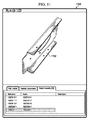
ここで、有利な実施形態によるパーツの一部の図を示す図10を参照する。この実施例では、パーツ1000は図6のパーツ・データベース618に含まれるパーツであってよい。
Reference is now made to FIG. 10, which shows a diagram of a portion of a part according to an advantageous embodiment. In this example,
この実施例では、パーツ1000は底面1002及び上面1004を有する。プライ1006の形態のレイヤは上面1004及び底面1002の間に含まれうる。この実施例では、平面1008はパーツ1000と交差する。平面1008は、ユーザによって定義することができ、たとえば図6の平面626であってよい。その他の実施例では、平面1008は図6のデータ抽出ツール612によって選択される平面であってよい。この実施例では、この交差はライン1010において上面1004に対し実質的に垂直であってよい。平面1008はプライデータを識別するためにパーツ1000との交差を形成する境界線として使用される仮想の数学的な平面である。
In this example,
この平面1008による平面的な交差は、図6のデータ抽出ツール612を使用して行うことができる。これらの実施例では、座標U及びVはパーツ1000のプライ1006との平面的交差を定義することができる。この実施例で示すように、パーツ1000はU座標に対するU軸1011と、V座標に対するV軸1012を有する。これらの軸は平面1008に相対的である。平面1008はパーツ1000内のプライ1006の各プライと交差する平面を定義する座標との境界線として使用される。
This planar intersection with the
プライ1006の各プライとの交差の結果が例えばライン1014、1016、1018、及び1020等のラインである。この実施例では、各ラインは平面1008と交差するプライの上部分を表す。当然ながら、パーツ1000の平面1008の交差において存在するプライの数によって、他のラインも存在しうる。これらのラインは平面1008に相対的なU及びV座標を使用して表すことができる。さらに、ラインによって表される交差には、X、Y、及びZ座標を使用した線形近似をあてはめることができる。つまり平面1008のU及びV座標をX、Y、及びZ座標、又はその他何らかの座標系に置きかえることが可能である。
The result of the intersection of the
この情報を基に、平面1008内の各ラインのプライデータを得ることができる。各ラインを、底面1002から始まって上面1004までの全てにおいて、次のラインの上部に配置することができる。このデータを使用してパーツ1000のプライ積層体データの提示内容を生成することができる。
Based on this information, ply data for each line in the
ここで、有利な実施形態による位置データを定義する図である図11〜13を参照する。図11において、パーツの図を有利な実施形態にしたがって示す。表示内容1100は図6のクライアント・アプリケーション608によって提示することができる表示内容の一例である。表示内容1100では、パーツ1102は三次元オブジェクトとして提示される。パーツ1102はユーザ入力を介して操作することができる。
Reference is now made to FIGS. 11-13, which are diagrams for defining position data according to an advantageous embodiment. In FIG. 11, a diagram of the parts is shown according to an advantageous embodiment. The
次に、有利な実施形態による平面の選択の図を示す図12を参照する。この実施例では、平面1200は表示内容1202のパーツ1102に対して選択される。平面1200は、平面1200が切断面に対して選択された位置を通るように選択される。
Reference is now made to FIG. 12, which shows a diagram of plane selection according to an advantageous embodiment. In this example,
平面1200の方向性はユーザが選択することができる。例えば、平面1200は、平面1200がパーツ1102の表面に対して垂直であるように選択することができる。その他の実施例では、平面1200はパーツ1102に対してあるその他の角度を成すように選択することができる。これらの実施例では、平面1200は、平面1200に対して垂直であるパーツ1102の一部が表示内容1202では見えない状態でパーツ1102を貫通することができる。その他の実施例では、表示内容1202に使用されるビューワによって、パーツ1102の全てを表示内容1202において見ることができる。
The direction of the
次に、有利な実施形態による位置の選択の図を示す図13に注目する。この実施例では、表示内容1302のポイント1300が切断面1302の位置1300として選択されている。さらに、平面1200は、平面1200がポイント1300を通過するように選択される。
Attention is now directed to FIG. 13, which shows a diagram of position selection according to an advantageous embodiment. In this embodiment, the
ここで、有利な実施形態によるプライ積層体データの提示の図を示す図14を参照する。この実施例では、表示内容1400は、図6のクライアント・アプリケーション608によって提示することができる表示内容の一例である。この実施例では、パーツの位置データの受信に応答して、パーツについて抽出されたプライ積層体データを表す。
Reference is now made to FIG. 14 showing a diagram of presentation of ply laminate data according to an advantageous embodiment. In this embodiment,
この実施例では、区画1402はパーツ1406の三次元モデル1404を示す。区画1408は、三次元モデル1404内のレイヤの識別を示す。この実施例では、区画1408のレイヤ1410が選択されている。レイヤ1410の選択に応答して、グラフィカルインジケータ1412がパーツ1404の三次元モデル1406において表示される。グラフィカルインジケータ1412は、三次元モデル1406のレイヤ1410を識別する。この実施例では、区画1408のレイヤ1410は三次元モデル1406のレイヤ1414に対応する。この実施例では、グラフィカルインジケータ1412はレイヤ1414の強調表示1416の形態をとる。
In this example,
レイヤ1414についての情報を区画1418に示す。この実施例では、区画1418はサンプリングの位置1420、材料1422、方向性情報1424、単位1426、及び基準軸1428等の情報を識別する。
Information about
この実施例では、グラフィカルインジケータ1412はまた、ポップアップウィンドウ1430も含むことができる。図示したように、ポップアップウィンドウ1430はこれらの実施例では選択されたレイヤ、レイヤ1410についてのデータを含む。
In this example,
図11〜14の表示内容の図は、物理的又はアーキテクチャ制限を暗示するように意図されたものではなく、異なる表示内容を提示することができる。その他の有利な実施形態では、その他の区画を示したものに加えて用いてもよい。加えて、区画は単一の表示内容においてでなく、異なるウィンドウ又は表示内容において別々に示すことができる。さらに、グリッドもまたある有利な実施形態において二次元で示す、又は二次元の図を使用することもできる。 The display content diagrams of FIGS. 11-14 are not intended to imply physical or architectural limitations, and different display content may be presented. In other advantageous embodiments, other compartments may be used in addition to those shown. In addition, compartments can be shown separately in different windows or display content, rather than in a single display content. Furthermore, the grid can also be shown in two dimensions in some advantageous embodiments, or a two-dimensional diagram can be used.
ここで、有利な実施形態によるパーツのモデルを処理するフロー図を示す図15を参照する。図15に示すプロセスを図6のデータ抽出ツール612において実行可能である。
Reference is now made to FIG. 15 which shows a flow diagram for processing a model of a part according to an advantageous embodiment. The process shown in FIG. 15 can be executed in the
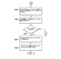
このプロセスは、パーツ上の複数の位置についての情報に対するクライアント・アプリケーションからの要求の受信に応答して、パーツモデルにおける複数の位置を識別することから開始する(操作1500)。これらの実施例ではモデルは三次元モデルである。当然ながら、二次元モデル等のその他のモデルを使用することができる。 The process begins by identifying multiple locations in the part model in response to receiving a request from a client application for information about multiple locations on the part (operation 1500). In these embodiments, the model is a three-dimensional model. Of course, other models such as a two-dimensional model can be used.
パーツモデルの複数の位置のそれぞれにおいて切断面を作成し、複数の切断面を形成する(操作1502)。複数の切断面のそれぞれの複数のレイヤについてのデータを取得する(操作1504)。複数の切断面を持つモデルを変更してクライアント・アプリケーションによって使用されるフォーマットを有するフォーマット済みのモデルを形成し、フォーマット済みのモデルを表示する(操作1506)。この実施例では、変更されたモデルは複数の切断面の情報又は識別を含む。 A cut surface is created at each of a plurality of positions of the part model, and a plurality of cut surfaces are formed (operation 1502). Data is acquired for each of the plurality of layers of the plurality of cut surfaces (operation 1504). The model having multiple cut planes is modified to form a formatted model having a format used by the client application and the formatted model is displayed (operation 1506). In this example, the modified model includes information or identification of multiple cut surfaces.
フォーマット済みのモデルの複数の切断面それぞれの複数のレイヤを、複数の切断面それぞれにおける複数のレイヤについてのデータと関連づけし、フォーマット済みのモデルとデータとの関連性を形成する(操作1508)。この関連性はメタデータを使用して形成することができる。メタデータは、パーツの特定レイヤのデータと、パーツのフォーマット済みのモデルの対応するレイヤとの相互の関連性を識別することができる。 Associating the plurality of layers of each of the plurality of cut surfaces of the formatted model with the data for the plurality of layers in each of the plurality of cut surfaces to form an association between the formatted model and the data (operation 1508). This association can be formed using metadata. The metadata can identify the relevance between the data for a particular layer of the part and the corresponding layer of the formatted model of the part.
ある有利な実施形態では、メタデータはフォーマット済みのモデルを提示することができるプログラム又はビューワの呼出しの識別を含むことができる。フォーマット済みのモデル、データ、及びメタデータをクライアント・アプリケーションへ応答して返し(操作1510)、その後プロセスは終了する。クライアント・アプリケーションは次に図面を表示することができ、クライアント・アプリケーションによって表示された操作の提示に応答して、整備作業を行うことができる。 In one advantageous embodiment, the metadata can include identification of a program or viewer call that can present a formatted model. The formatted model, data, and metadata are returned in response to the client application (operation 1510), after which the process ends. The client application can then display the drawing and perform maintenance work in response to the presentation of the operation displayed by the client application.
ここで、有利な実施形態によるパーツ上の位置を選択するプロセスのフロー図を示す図16に注目する。図16に示すプロセスを図6のクライアント・アプリケーション608において実行することができる。
Attention is now directed to FIG. 16, which shows a flow diagram of a process for selecting a position on a part according to an advantageous embodiment. The process illustrated in FIG. 16 may be performed in the
このプロセスは、パーツの三次元モデルを表示することによって開始する(操作1600)。プロセスは次にユーザ入力を待機する(操作1602)。このユーザ入力は例えば非限定的に、モデルの操作、モデル上の位置の選択、及び/又は位置情報を発信してプライ積層体データを取得する等の様々な形態のものであってよい。 The process begins by displaying a three-dimensional model of the part (operation 1600). The process then waits for user input (operation 1602). This user input may take various forms, such as, for example, without limitation, operating the model, selecting a position on the model, and / or transmitting position information to obtain the ply laminate data.
ユーザ入力が三次元モデルの処理であるか否かが判断される(操作1604)。ユーザ入力が三次元モデルを処理することである場合、処理が実施され(操作1606)、プロセスは操作1602に戻る。操作1606では、ユーザ入力は例えばオブジェクトを回転させる、拡大する、パニングする等、様々な動作のためであってよい。
It is determined whether or not the user input is processing of a three-dimensional model (operation 1604). If the user input is to process a 3D model, processing is performed (operation 1606) and the process returns to
操作1604において、ユーザ入力がモデルを処理することでない場合、ユーザ入力がモデル上の位置を選択することか否かが判断される(操作1608)。ユーザ入力が位置を選択すると、ユーザの選択に基づいて位置データが識別される(操作1610)。操作1610における位置データの識別では、ユーザ入力で選択された位置の座標が識別される。これらの座標はパーツの座標系に対しての座標であってよい。
In
位置データが表示され(操作1612)、プロセスは次に上述した操作1602に戻る。この位置データは例えば、X、Y、及びZ座標の形態であってよい。さらに、位置をパーツの三次元モデル上に図式的に示すことができる。
The position data is displayed (operation 1612) and the process then returns to
操作1608を再び参照する。ユーザ入力がモデル上の位置を選択しない場合、ユーザ入力は平面を選択することか否かが判断される(操作1614)。ユーザ入力が平面の選択であった場合、平面は位置データの一部として識別され(操作1616)、プロセスは上述したように操作1602に戻る。
Refer to
再び操作1614を参照する。ユーザ入力が平面を選択しない場合、ユーザ入力が位置データを発信することか否かが判断される(操作1618)。これらの実施例では、位置データはユーザ入力によって選択された位置及び平面を含む。ユーザ入力が位置データを発信することである場合、位置データが送られ(操作1620)、その後プロセスは終了する。これらの実施例では、位置データを例えば図6のクライアント・アプリケーション608又はデータ抽出ツール612等の別のアプリケーションに送ることができる。
Reference is again made to
操作1618に戻り、ユーザ入力が位置データを発信するものでない場合、ユーザ入力がプロセスを終了させることか否かが判断される(操作1622)。ユーザ入力がプロセスの終了である場合、プロセスは終了する。そうでなければ、プロセスは操作1602に戻り、さらなるユーザ入力を待機する。この場合、ユーザ入力はこの図面に示すプロセスによって処理されない幾つかの入力である。
Returning to operation 1618, if the user input does not originate position data, it is determined whether the user input terminates the process (operation 1622). If the user input is an end of process, the process ends. Otherwise, the process returns to
ここで、有利な実施形態によるパーツについての情報を表示するプロセスのフロー図を示す図17に注目する。図17に示すプロセスは、図6のクライアント・アプリケーション608において実行可能である。このプロセスは、図6のクライアント・アプリケーション608が応答646を受信した時に開始することができる。
Attention is now directed to FIG. 17, which shows a flow diagram of a process for displaying information about parts according to an advantageous embodiment. The process shown in FIG. 17 can be executed in the
このプロセスはパーツの三次元モデルを表示することによって開始する(操作1700)。操作1700は、応答で返されたパーツのフォーマット済みのモデルを使用して行うことができる。その後、プロセスは複数の切断面それぞれのレイヤのリストを表示する(操作1702)。操作1702は応答に含まれるレイヤのデータを使用して行うことができる。これらの実施例では、データは拡張マークアップ言語(XML)のフォーマットのものであってよい。
The process begins by displaying a three-dimensional model of the part (operation 1700).
次に、プロセスはユーザ入力を監視する(操作1704)。ユーザ入力を受信したか否かが判断される(操作1706)。ユーザ入力を受信していない場合、プロセスは操作1706に戻る。
Next, the process monitors user input (operation 1704). It is determined whether a user input has been received (operation 1706). If no user input has been received, the process returns to
そうでない場合、ユーザ入力が三次元モデルの処理であるか否かが判断される(操作1708)。この処理は例えばオブジェクトの回転、オブジェクトのサイズ変更、オブジェクトへの注記添付、又はその他何らかの好適な操作であってよい。ユーザ入力がモデルの処理である場合、プロセスはこの処理を行い(操作1710)、このプロセスはプロセス1706に戻る。 Otherwise, it is determined whether the user input is a 3D model process (operation 1708). This process may be, for example, rotation of the object, resizing of the object, attaching notes to the object, or some other suitable operation. If the user input is a model process, the process performs this process (operation 1710), and the process returns to process 1706.
再び操作1708を参照する。ユーザ入力がモデルの処理でない場合、ユーザ入力がレイヤのリストからのレイヤの選択であるか否かが判断される(操作1712)。ユーザ入力がレイヤのリストからのレイヤの選択である場合、プロセスはレイヤのリストの中の選択されたレイヤを図式的に示す(操作1714)。その後、プロセスは選択されたレイヤについての情報を表示する(操作1716)。このプロセスはまた、選択されたレイヤに対応する三次元モデルの切断面のレイヤを図式的に示し(操作1718)、プロセスは上述した操作1704に戻る。これらの実施例では、図式的な表示には、例えば選択されたレイヤの強調表示、選択されたレイヤの点滅、選択されたレイヤの色の変更、及び/又はその他好適な表示であってよい。
Reference is again made to
操作1712に戻り、ユーザ入力がレイヤのリストからのレイヤの選択でない場合、プロセスは応答の提示に対していかなる操作も行わない。このプロセスは次に操作1704に戻る。
Returning to
ここで、有利な実施形態による切断面を作成するプロセスのフロー図を示す図18A及び18Bに注目する。図18A及び18Bのプロセスは、例えば図7のデータ抽出ツール700等のソフトウェアコンポーネントにおいて実行可能である。図18A及び18Bのプロセスは、図11の表示内容1100に対して説明したように、プライ積層体データを生成するのに使用できるプロセスの一例である。
Attention is now directed to FIGS. 18A and 18B showing a flow diagram of a process for creating a cut surface according to an advantageous embodiment. The process of FIGS. 18A and 18B can be performed in a software component such as, for example, the
プロセスは選択された位置においてプライを支持する底面を識別することによって開始する(操作1800)。これらの実施例では、底面はプライを支持する表面である。次に、底面をある平面によって交差させる(操作1802)。この交差により、平面とプライの間に交差ができる。これらの実施例では、平面は例えば図6の平面626であってよい。底面と平面の交差の線形近似が行われる(操作1804)。
The process begins by identifying the bottom surface that supports the ply at the selected location (operation 1800). In these embodiments, the bottom surface is the surface that supports the ply. Next, the bottom surfaces are crossed by a certain plane (operation 1802). This crossing creates a cross between the plane and the ply. In these embodiments, the plane may be, for example,
この結果得られたU及びV座標はベース座標アレイに記憶される(操作1806)。操作1806の結果は、X、Y、及びZ座標を有する一連のポイントである。ポイントは全て、それ自体のU及びV座標系を有する平面上にある。平面上のポイントは、平面の基点に対してU及びV座標を有する。
The resulting U and V coordinates are stored in the base coordinate array (operation 1806). The result of
これらの座標は上部座標アレイにコピーされる(操作1808)。この時点で、ベース座標アレイと上部座標アレイは同じ値を有する。区画において異なるプライを処理していくと、上部座標アレイが更新される。上部座標アレイの最終的な値は区画の最上部のプライの上面である。 These coordinates are copied to the upper coordinate array (operation 1808). At this point, the base coordinate array and the top coordinate array have the same value. As the different plies are processed in the partition, the upper coordinate array is updated. The final value of the top coordinate array is the top surface of the top ply of the compartment.
その後、底面に最も近い平面が交差する未処理のプライが識別される(操作1816)。プライと平面の交差の線形近似が行われる(操作1818)。結果として得られたU及びV座標は座標アレイに記憶される(操作1820)。 Thereafter, an unprocessed ply whose plane closest to the bottom surface intersects is identified (operation 1816). A linear approximation of the intersection of the ply and the plane is performed (operation 1818). The resulting U and V coordinates are stored in the coordinate array (operation 1820).
次に、座標アレイにおける座標の方向がベース座標アレイの座標の方向と同じであるか否かが判断される(操作1822)。座標が同じ方向でない場合、座標アレイの座標の値の方向を逆にして、ベース座標アレイと同じ方向に一致させる(操作1824)。 Next, it is determined whether the coordinate direction in the coordinate array is the same as the coordinate direction in the base coordinate array (operation 1822). If the coordinates are not in the same direction, the direction of the coordinate values in the coordinate array is reversed to match the same direction as the base coordinate array (operation 1824).
プライと平面の交差が作成された場合、結果として一又は複数の曲面が得られる。これらの曲面はプロセスによって使用される固有の開始及び終了点を有する。プロセスはベース座標アレイに対して垂直である方向のセグメントの開始及び終了点を上部座標アレイに投影する(操作1826)。プロセスは、座標アレイとベース座標アレイの座標の方向が同じである場合、操作1822からこの操作に直接進む。
If a ply-plane intersection is created, the result is one or more curved surfaces. These curved surfaces have unique start and end points used by the process. The process projects the start and end points of the segment in a direction perpendicular to the base coordinate array onto the upper coordinate array (operation 1826). The process proceeds directly from
このプロセスは、上部座標アレイの一部をプライの厚さによってセグメント終了点の間にオフセットする(操作1828)。操作1828では、上部座標アレイの値を変更して処理中のプライの上部を反映させる。このオフセットは空間におけるプライの実際の位置を表す。プロセスは次に上部座標アレイを更新して、プライの上部を反映させる(操作1830)。
This process offsets a portion of the top coordinate array between segment end points by the ply thickness (operation 1828). In
プライ及び平面の交差曲面の終了点が上部座標アレイにおいて定義されたラインセグメント上に投影され、プライの底部が定義される。終了点間のセグメントは基準化された厚さによってオフセットされ、プライの上部が定義される。次に、さらに未処理のプライがあるか否かが判断される(操作1832)。さらなるプライがある場合、プロセスは上述した操作1816に戻り、底面に最も近い平面が交差する未処理のプライを識別する。
The end points of the ply and plane intersecting surfaces are projected onto the line segments defined in the top coordinate array to define the bottom of the ply. The segment between the end points is offset by the normalized thickness to define the top of the ply. Next, it is determined whether there are any more unprocessed plies (operation 1832). If there are more plies, the process returns to
さらに未処理のプライがない場合、プロセスは出力するための各プライのオフセットセグメントを描く又は作成する(操作1834)。プライに対するこれらのオフセットセグメントを二次元モデルに使用してプライのスタッキング・シーケンスが識別される。プロセスはセグメントにラベル付けをし、これにより各セグメントを識別することができ(操作1836)、その後プロセスは終了する。 If there are no more unprocessed plies, the process draws or creates an offset segment for each ply to output (operation 1834). These offset segments for the plies are used in the two-dimensional model to identify the ply stacking sequence. The process labels the segments so that each segment can be identified (operation 1836), after which the process ends.
これらの実施例では、操作1800〜1826は、例えば図7のデータ抽出ツール700内のコア識別装置702等の装置において実行可能である。操作1828及び1830は、例えば図7のコアサンプリング装置706等の装置において実行可能である。操作1834及び1836は、例えば図7の出力生成装置708等の装置において実行可能である。
In these illustrative examples, operations 1800-1826 may be performed on a device such as
これらの実施例では、平面はXベクトル及びYベクトルに対して直角を成すように作成される。これらの平面は様々な間隔を有することができる。例えば、損傷位置に対し、X平面はX=−18〜X=+18の値域であってよく、Y平面はY=−18〜Y=+18の値域であってよい。平面の値域は、選択された値に対してパーツが平面まで延在しない場合はより狭いものであってよい。選択された平面で複数の切断面が作成される。これらの異なる切断面はパーツの長さ及び幅に基づくものである。しかしながら切断面はこれらの実施例では、3インチを下回らないデフォルト値を有する。実際の間隔は、全ての切断面が同じ間隔離れているように調節することができる。当然ながら、特定の実行形態によってその他のデフォルト値を使用することができる。 In these embodiments, the plane is created to be perpendicular to the X and Y vectors. These planes can have various spacings. For example, with respect to the damage position, the X plane may be in the range of X = −18 to X = + 18, and the Y plane may be in the range of Y = −18 to Y = + 18. The range of the plane may be narrower if the part does not extend to the plane for the selected value. A plurality of cutting planes are created on the selected plane. These different cut planes are based on the length and width of the part. However, the cutting plane in these examples has a default value not less than 3 inches. The actual spacing can be adjusted so that all cut surfaces are the same spacing. Of course, other default values may be used depending on the particular implementation.
実施例として、損傷位置がパーツの縁から16インチのところにある場合、X方向の切断面の値域は合計34インチに対してー16〜+18となる。間隔が6インチに特定された場合、これは5.667に調節され、切断面は下記Xの値:−16、−10.333、−4.667、1、6.667、12.333、および18において作成される。別の実施例として、パーツの幅が14インチであり、損傷がパーツの中央にあり、3インチの間隔が要求されている場合、2.8インチずつ離れている切断面を提供する間隔を調節することができる。これらの切断面はXの値において下記:−7、−4.2、−1.4、1.4、4.2、及び7.7であってよい。 As an example, if the damage location is 16 inches from the edge of the part, the value range of the cut surface in the X direction is -16 to +18 for a total of 34 inches. If the spacing is specified as 6 inches, this will be adjusted to 5.667 and the cut plane will have the following X values: -16, -10.333, -4.667, 1, 6.667, 12.333, And 18. As another example, if the part width is 14 inches, the damage is in the middle of the part, and a 3 inch spacing is required, adjust the spacing to provide a cut surface that is 2.8 inches apart can do. These cut planes may have the following X values: -7, -4.2, -1.4, 1.4, 4.2, and 7.7.
図示した異なる実施形態のフロー図及びブロック図は、装置、方法、コンピュータプログラム製品の幾つかの可能な実行形態のアーキテクチャ、機能性、及び動作を示す。これに関して、フロー図又はブロック図の各ブロックは、動作又はステップのモジュール、セグメント、又は特定の一つの機能又は複数の機能を実行するための一又は複数の実行可能な命令を含むコンピュータが使用可能な、又はコンピュータによって読み取り可能なプログラムコードの部分を提示しうる。幾つかの代替実行形態において、ブロックに注記された一つの機能又は複数の機能は、図面に注記された順番以外の順番で実施可能である。例えば、ある場合には、関連する機能性に依存して、連続して示す2つのブロックは実質的に同時に実行可能である、又はブロックはしばしば逆の順に実行することができる。 The flowcharts and block diagrams in the different illustrated embodiments illustrate the architecture, functionality, and operation of some possible implementations of apparatuses, methods and computer program products. In this regard, each block in the flow diagram or block diagram is usable by a computer that includes a module or segment of operations or steps, or one or more executable instructions for performing a particular function or functions. Or a portion of program code readable by a computer. In some alternative implementations, the function or functions noted in the block may be performed in an order other than the order noted in the drawings. For example, in some cases, depending on the functionality involved, two blocks shown in succession can be executed substantially simultaneously, or the blocks can often be executed in reverse order.
このため、異なる有利な実施形態はパーツのモデルを処理する方法及び装置を提供する。パーツ上の複数の位置についての情報に対するクライアント・アプリケーションからの要求の受信に応答して、パーツモデルにおける複数の位置を識別する。パーツのモデルにおける位置のそれぞれにおいて切断面を作成して、複数の切断面を形成する。複数の切断面のそれぞれの複数のレイヤについてのデータを取得する。複数の切断面を持つモデルを変更して、クライアント・アプリケーションによって使用されるフォーマットを有するフォーマット済みのモデルを形成し、フォーマット済みのモデルを表示する。フォーマット済みのモデルの複数の切断面それぞれの複数のレイヤを、複数の切断面それぞれにおける各レイヤについてのデータと関連づけして、フォーマット済みのモデルとデータとの関連性を形成する。フォーマット済みのモデル及びデータをクライアント・アプリケーションに応答して返す。 Thus, the different advantageous embodiments provide a method and apparatus for processing a model of a part. In response to receiving a request from the client application for information about multiple locations on the part, the multiple locations in the part model are identified. A cut surface is created at each position in the part model to form a plurality of cut surfaces. Data on each of the plurality of layers of the plurality of cut surfaces is acquired. Modify the model with multiple cut planes to form a formatted model having a format used by the client application and display the formatted model. The layers of each of the plurality of cut surfaces of the formatted model are associated with data for each layer in each of the plurality of cut surfaces to form a relationship between the formatted model and the data. Returns the formatted model and data in response to the client application.
図示した実施例では、フォーマット済みのモデルは整備作業で要求される不必要な情報を除外することができる。さらに、フォーマット済みのモデルはまた内密の又は企業秘密と考慮できる情報も除外することができる。さらに、フォーマット済みのモデルとデータは、ユーザ又はオペレータがコンピュータを使った設計プログラムを持つ必要なく提示することができる。フォーマット済みのモデルとデータは、フォーマット済みのモデルを表示するビューワを使用してウェブブラウザにおいて提示することができる。 In the illustrated embodiment, the formatted model can exclude unnecessary information required for maintenance operations. In addition, the formatted model can also exclude information that can be considered confidential or trade secret. Further, the formatted model and data can be presented without the need for the user or operator to have a design program using a computer. The formatted model and data can be presented in a web browser using a viewer that displays the formatted model.
異なる有利な実施形態は、全体的にハードウェアの実施形態、全体的にソフトウェアの実施形態、又はハードウェア及びソフトウェア要素を両方含む実施形態の形態をとることができる。ある実施形態は、例えばファームウェア、常駐ソフトウェア、及びマイクロコード等の形態を非限定的に含むソフトウェアにおいて実行される。 The different advantageous embodiments may take the form of an entirely hardware embodiment, an entirely software embodiment or an embodiment containing both hardware and software elements. Certain embodiments are implemented in software, including but not limited to forms such as firmware, resident software, and microcode.
さらに、異なる実施形態は、命令を実行するコンピュータ、又は全てのデバイス、又はシステムによって、あるいはこれらと接続して使用されるプログラムコードを提供するコンピュータが使用可能な又はコンピュータによって読取可能な媒体からアクセス可能なコンピュータプログラム製品の形態をとることができる。この説明のために、コンピュータで使用可能な又はコンピュータによって読取可能な媒体は概して、命令実行システム、装置、又はデバイスによって、又はこれらと接続して使用されるプログラムを含む、記憶する、通信する、伝播する、又は運搬することができる全ての有形装置であってよい。 Further, different embodiments may be accessed from a computer that can execute instructions, or a computer that provides program code for use by or in connection with any device or system, or from a computer readable medium. It can take the form of a possible computer program product. For purposes of this description, computer usable or computer readable media generally includes, stores, communicates with, and includes programs used by or in connection with an instruction execution system, apparatus, or device. It can be any tangible device that can propagate or carry.
コンピュータが使用可能な又はコンピュータによって読み取り可能な媒体は例えば非限定的に、電子、磁気、光、電磁気、赤外線、又は半導体システム、又は伝播媒体であってよい。コンピュータによって読み取り可能な媒体の非限定的な例には、半導体又は固体メモリ、磁気テープ、取外し可能なフロッピーディスク(登録商標)、ランダムアクセスメモリ(RAM)、リードオンリメモリ(ROM)、固体磁気ディスク、及び光ディスクが含まれる。光ディスクには、コンパクトディスク−リードオンリーメモリ(CD−ROM)、コンパクトディスク−リード/ライト(CD−R/W)、及びDVDが含まれうる。 The computer usable or computer readable medium may be, for example but not limited to, an electronic, magnetic, optical, electromagnetic, infrared, or semiconductor system, or a propagation medium. Non-limiting examples of computer readable media include semiconductor or solid state memory, magnetic tape, removable floppy disk, random access memory (RAM), read only memory (ROM), solid state magnetic disk. And optical discs. Optical disks can include compact disk-read only memory (CD-ROM), compact disk-read / write (CD-R / W), and DVD.
さらに、コンピュータが使用可能な、又はコンピュータによって読み取り可能な媒体はコンピュータによって読み取り可能な、又はコンピュータが使用可能なプログラムコードを含む又は記憶することができ、これによりコンピュータによって読み取り可能な、又はコンピュータが使用可能なプログラムコードがコンピュータ上で実行された時に、このコンピュータによって読み取り可能な、又はコンピュータが使用可能なプログラムコードの実行により、コンピュータが別のコンピュータによって読み取り可能な、又はコンピュータが使用可能なプログラムコードを通信リンク上で送信する。この通信リンクは例えば非限定的に、物理的又は無線の媒体を使用することができる。 Further, a computer usable or computer readable medium may contain or store program code that can be read by a computer or used by a computer so that the computer readable or A program that can be read by another computer when the usable program code is executed on the computer, or that can be read by another computer by execution of the program code that can be used by the computer, or a computer that can be used by the computer Send the code over the communication link. This communication link may use, for example, without limitation, a physical or wireless medium.
コンピュータによって読み取り可能な、又はコンピュータが使用可能なプログラムコードを記憶する及び/又は実行するのに好適なデータ処理システムは、例えばシステムバス等の通信ファブリックを通してメモリ要素に直接又は間接的に結合した一又は複数のプロセッサを含む。メモリ要素は、少なくとも幾つかのコンピュータによって読み取り可能な、又はコンピュータが使用可能なプログラムコードの一時記憶装置を提供してコードを実行中に大容量記憶装置からコードを読み出す可能性のある回数を減らす、プログラムコードを実際に実行中に用いられるローカルメモリ、大容量記憶装置、及びキャッシュメモリを含むことができる。 A data processing system suitable for storing and / or executing computer readable or computer usable program code is one that is coupled directly or indirectly to memory elements through a communication fabric such as a system bus. Or a plurality of processors are included. The memory element provides a temporary storage of program code that is readable or usable by at least some computers to reduce the number of times that the code may be read from the mass storage device while executing the code. , Local memory, mass storage, and cache memory used during actual execution of program code.
入力/出力又はI/Oデバイスを、直接に、又は介在するI/Oコントローラを介してのいずれかによってシステムに結合させることができる。これらのデバイスは例えば非限定的に、キーボード、タッチスクリーンディスプレイ、及びポインティング・デバイスを含むことができる。異なる通信アダプタをシステムに結合させて、データ処理システムを介在する構内又は公衆ネットワークを介してその他のデータ処理システム又はリモートプリンタ、又は記憶デバイスに結合させることが可能になる。非限定的な実施例はモデム及びネットワークアダプタであり、これらは現在入手可能な種類の通信アダプタのうちのほんの一部である。 Input / output or I / O devices can be coupled to the system either directly or through an intervening I / O controller. These devices can include, for example, without limitation, keyboards, touch screen displays, and pointing devices. Different communication adapters can be coupled to the system and coupled to other data processing systems or remote printers, or storage devices via a premises or public network through the data processing system. Non-limiting examples are modems and network adapters, which are just a few of the currently available types of communication adapters.
異なる有利な実施形態の記載は、図示及び説明の目的のために提示されたものであり、包括的、又は開示された形の実施形態に限定するように意図されたものではない。当業者には多数の修正及び変形例が明らかである。 The description of the different advantageous embodiments has been presented for purposes of illustration and description, and is not intended to be exhaustive or limited to the embodiments in the form disclosed. Many modifications and variations will be apparent to practitioners skilled in this art.
例えば、異なる有利な実施形態を航空機に関して説明してきたが、異なる有利な実施形態は幾つかの有利な実施形態をその他の種類のプラットフォームに応用することができることを認識する。プラットフォームは、プラットフォーム内部のレイヤについての情報が必要となるいかなるプラットフォームであってもよい。この情報は整備、パーツの再加工、パーツの試験、及びその他の好適な目的で使用することができる。プラットフォームは例えば非限定的に、可動プラットフォーム、固定プラットフォーム、陸上構造物、水上構造物、宇宙構造物、及び/又はその他何らかの適切な物体であってよい。さらに具体的には、異なる有利な実施形態は例えば非限定的に、潜水艦、バス、人員運搬車、タンク、列車、自動車、宇宙船、宇宙ステーション、衛星、水上艦、発電所、ダム、製造施設、建造物、及び/又はその他何らかの適切な物体に応用することができる。 For example, while different advantageous embodiments have been described with respect to an aircraft, it will be appreciated that the different advantageous embodiments may apply some advantageous embodiments to other types of platforms. The platform can be any platform that requires information about the layers within the platform. This information can be used for maintenance, part rework, part testing, and other suitable purposes. The platform may be, for example, without limitation, a movable platform, a fixed platform, a land structure, a water structure, a space structure, and / or any other suitable object. More specifically, the different advantageous embodiments include, but are not limited to, submarines, buses, personnel carriers, tanks, trains, automobiles, spacecraft, space stations, satellites, surface ships, power plants, dams, manufacturing facilities. , Buildings, and / or any other suitable object.
さらに、他の有利な実施形態と比較して、異なる有利な実施形態により異なる利点を得ることが可能である。選択された一又は複数の実施形態は、実施形態及び実際の応用形態の原理を最適に説明するため、また、当業者が、考えられる特定の使用に好適である様々な修正を施した様々な実施形態の開示を理解できるように選択され記載されたものである。
また、本発明は以下に記載する態様を含む。
(態様1)
パーツ(622)のモデルを処理する方法であって:
パーツ(622)上の複数の位置(624)についての情報に対するクライアント・アプリケーション(608)からの要求の受信に応答して、パーツ(622)のモデルにおける複数の位置(624)を識別(1500)し、
パーツ(622)のモデルにおける複数の位置(624)のそれぞれにおいて切断面を作成(1502)して、複数の切断面(634)を形成し、
複数の切断面(634)のそれぞれの複数のレイヤ(636)についてのデータが取得(1504)し、
複数の切断面(634)を有するモデルを変更(1506)して、クライアント・アプリケーション(608)によって使用されるフォーマット(642)を有するフォーマット済みのモデル(640)を形成し、フォーマット済みのモデル(640)を表示し、
フォーマット済みのモデル(640)の複数の切断面(634)それぞれの複数のレイヤ(636)を、複数の切断面(634)それぞれにおける複数のレイヤ(636)についてのデータと関連づけ(1508)して、フォーマット済みのモデル(640)とデータ(638)との関連性(644)を形成し、
クライアント・アプリケーション(608)に応答して、フォーマット済みのモデル(640)及び複数のレイヤ(636)についてのデータを返す(1510)
ことを含む方法。
(態様2)
複数の切断面(830)に対する平面を識別(810)する
ことをさらに含む、態様1に記載の方法。
(態様3)
データ(638)が延長マークアップ言語フォーマットにフォーマット変更されている、態様1に記載の方法。
(態様4)
クライアント・アプリケーション(608、800)がウェブブラウザ(820)を含む、態様1に記載の方法。
(態様5)
クライアント・アプリケーション(608、800)がフォーマット済みのモデル(640)を提示するウェブブラウザ(820)用のプラグイン(822)をさらに含む、態様4に記載の方法。
(態様6)
クライアント・アプリケーション(608、800)がコンピュータを使った設計ファイル用のビューワ(824)を含む、態様1に記載の方法。
(態様7)
フォーマット済みのモデル(640)の複数の切断面(634)それぞれの複数のレイヤ(636)を、複数の切断面(634)それぞれにおける複数のレイヤ(636)についてのデータ(638)と関連づけ(1508)して、フォーマット済みのモデル(642)とデータ(638)との関連性(644、826)を形成するステップが:
複数の切断面(634、830)それぞれの複数のレイヤ(636、828)のデータ(638、818)を、フォーマット済みのモデル(640)の複数の切断面(634、830)それぞれのレイヤと相互に関連付けするメタデータ(834)を作成するステップであって、メタデータ(834)が応答(646、818)に含まれるステップ
を含む、態様1に記載の方法。
(態様8)
複数のレイヤ(636、828)についてのデータ(638、818)とメタデータ(834)が、ウェブページ内の複数のレイヤ(636、828)についてのデータ(638、818)の選択に応答して、フォーマット済みのモデル(640)のレイヤを示すためにビューワ(824)を呼び出すプログラムコードを有するウェブページ内に返される、態様7に記載の方法。
(態様9)
パーツ(622)が複合パーツであり、複数のレイヤ(636、828)が複合パーツ内の複数のプライ(302)である、態様1に記載の方法。
(態様10)
複合パーツが航空機(200)用である、態様9に記載の方法。
(態様11)
バス(502)と、
バス(502)に接続されたメモリ(506)であって、プログラムコード(518)が記憶されたメモリ(506)と、
パーツ(622)上の複数の位置(624)についての情報に対するクライアント・アプリケーション(608)からの要求の受信に応答して、パーツ(622)のモデルにおける複数の位置(624)を識別(1500)し;パーツ(622)のモデルにおける複数の位置(624)のそれぞれにおいて切断面を作成(1502)して、複数の切断面(634)を形成し;複数の切断面(634)のそれぞれの複数のレイヤ(636)についてのデータを取得(1504)し;複数の切断面(634)を有するモデルを変更(1506)して、クライアント・アプリケーション(608)によって使用されるフォーマットを有するフォーマット済みのモデル(640)を形成して、フォーマット済みのモデル(640)を表示し;フォーマット済みのモデル(640)の複数の切断面(634)それぞれの複数のレイヤ(636)を、複数の切断面(634)それぞれにおける複数のレイヤ(636)についてのデータ(638)と関連づけ(1508)して、フォーマット済みのモデル(640)とデータ(638)との関連性(644)を形成し;クライアント・アプリケーション(608)に応答して、フォーマット済みのモデル(640)及び複数のレイヤ(636)についてのデータ(638)を返すためにプログラムコード(518)を実行するプロセッサ装置(504)
を含む装置。
(態様12)
クライアント・アプリケーション(608、800)がウェブブラウザ(820)を含む、態様11に記載の装置。
(態様13)
クライアント・アプリケーション(608、800)がフォーマット済みのモデル(640)を提示するウェブブラウザ(820)用のプラグイン(822)をさらに含む、態様12に記載の装置。
(態様14)
クライアント・アプリケーション(608、800)がコンピュータを使った設計ファイル用のビューワ(824)を含む、態様11に記載の装置。
(態様15)
フォーマット済みのモデル(640)の複数の切断面(634,830)それぞれの複数のレイヤ(636、828)を、複数の切断面(634,830)それぞれにおける複数のレイヤ(636、828)についてのデータ(638)と関連づけ(1508)して、フォーマット済みのモデル(640)とデータ(638)との関連性(644)を形成するステップにおいて、プロセッサ装置(504)が、プログラムコード(518)を実行して、複数の切断面(634、830)のそれぞれの複数のレイヤ(636、828)についてのデータ(638)を、メタデータ(834)が応答(646、814)に含まれるフォーマット済みのモデル(640)の複数の切断面(634、830)それぞれのレイヤと相互に関連付けするメタデータ(834)を作成する、態様11に記載の装置。
(態様16)
パーツ(622)が複合パーツであり、複数のレイヤ(636、828)が複合パーツ内の複数のプライ(302)である、態様11に記載の装置。
(態様17)
複合パーツが航空機(200)用である、態様16に記載の装置。
(態様18)
パーツ(622)のモデルを処理するコンピュータプログラム製品(522)であって:
コンピュータによって記録可能な記憶媒体(524)、
コンピュータによって記録可能な記憶媒体(524)に記憶されたプログラムコード(518)であって、パーツ(622)上の複数の位置についての情報に対するクライアント・アプリケーション(608)からの要求の受信に応答して、パーツ(622)のモデルにおける複数の位置(624)を識別(1500)するプログラムコード(518)、
コンピュータによって記録可能な記憶媒体(524)に記憶されたプログラムコード(518)であって、パーツ(622)のモデル内の複数の位置(524)それぞれにおいて切断面を作成して複数の切断面(634)を形成するプログラムコード(518)、
コンピュータによって記録可能な記憶媒体(524)に記憶されたプログラムコード(518)であって、複数の切断面(634)それぞれにおける複数のレイヤ(636)についてのデータを取得する(1504)プログラムコード(518)、
コンピュータによって記録可能な記憶媒体(524)に記憶されたプログラムコード(518)であって、複数の切断面(634)を有するモデルを変更(1506)して、クライアント・アプリケーション(608)によって使用されるフォーマットを有するフォーマット済みのモデル(640)を形成してフォーマット済みのモデル(640)を表示するプログラムコード(518)、
コンピュータによって記録可能な記憶媒体(524)に記憶されたプログラムコード(518)であって、フォーマット済みのモデル(640)内の複数の切断面(634)のそれぞれにおける複数のレイヤ(636)を、複数の切断面(634)それぞれにおける複数のレイヤ(636)についてのデータ(638)と関連付け(1508)して、フォーマット済みのモデル(640)とデータ(638)との関連性(644)を形成するプログラムコード(518)、
コンピュータによって記録可能な記憶媒体(524)に記憶されたプログラムコード(518)であって、クライアント・アプリケーション(608)へ応答して、フォーマット済みのモデル(640)と複数のレイヤ(636)についてのデータ(638)を返す(1510)プログラムコード(518)
を含むコンピュータプログラム製品(522)。
(態様19)
コンピュータによって記録可能な記憶媒体(524)に記憶されたプログラムコード(518)であって、複数の切断面(634、830)の平面(810)を識別するためのプログラムコード(518)
をさらに含む、態様18に記載のコンピュータプログラム製品。
(態様20)
コンピュータによって記録可能な記憶媒体(524)に記憶されたプログラムコード(518)であって、フォーマット済みのモデル(640)内の複数の切断面(634、830)のそれぞれにおける複数のレイヤ(636、828)を、複数の切断面(634、830)それぞれにおける複数のレイヤ(636,828)についてのデータ(638)と関連付け(1508)して、フォーマット済みのモデル(640)とデータ(638)との関連性(644)を形成するプログラムコード(518)が、
コンピュータによって記録可能な記憶媒体(524)に記憶されたプログラムコード(518)であって、複数の切断面(634、830)のそれぞれの複数のレイヤ(636、828)についてのデータ(638)を、メタデータ(834)が応答(646、814)に含まれるフォーマット済みのモデル(640)の複数の切断面(634、830)それぞれのレイヤと相互に関連付けするメタデータ(834)を作成するプログラムコード(518)
を含む、態様18に記載のコンピュータプログラム製品。
Furthermore, different advantages can be obtained with different advantageous embodiments compared to other advantageous embodiments. The selected embodiment or embodiments may be best described in terms of the principles of the embodiment and actual application, and various modifications may be made by those skilled in the art, suitable for the particular use envisaged. It has been chosen and described so that the disclosure of the embodiments may be understood.
Moreover, this invention includes the aspect described below.
(Aspect 1)
A method for processing a model of a part (622) comprising:
In response to receiving a request from the client application (608) for information about a plurality of locations (624) on the part (622), the plurality of locations (624) in the model of the part (622) are identified (1500). And
A cut surface is created (1502) at each of a plurality of positions (624) in the model of the part (622) to form a plurality of cut surfaces (634),
Data for each of the plurality of layers (636) of the plurality of cut surfaces (634) is acquired (1504),
A model having a plurality of cut planes (634) is modified (1506) to form a formatted model (640) having a format (642) used by the client application (608), and the formatted model ( 640)
Associating (1508) the plurality of layers (636) of each of the plurality of cut surfaces (634) of the formatted model (640) with the data for the plurality of layers (636) in each of the plurality of cut surfaces (634). Form an association (644) between the formatted model (640) and the data (638),
In response to the client application (608), returns data for the formatted model (640) and multiple layers (636) (1510).
A method involving that.
(Aspect 2)
Identify (810) planes for multiple cut planes (830)
The method of
(Aspect 3)
The method of
(Aspect 4)
The method of
(Aspect 5)
The method of aspect 4, wherein the client application (608, 800) further includes a plug-in (822) for the web browser (820) that presents the formatted model (640).
(Aspect 6)
The method of
(Aspect 7)
Associating the plurality of layers (636) of each of the plurality of cut planes (634) of the formatted model (640) with the data (638) for the plurality of layers (636) in each of the plurality of cut planes (634) (1508) ) To form an association (644, 826) between the formatted model (642) and the data (638):
The data (638, 818) of the plurality of layers (636, 828) of each of the plurality of cut planes (634, 830) is mutually exchanged with the respective layers of the plurality of cut planes (634, 830) of the formatted model (640). Creating metadata (834) to be associated with, wherein the metadata (834) is included in the responses (646, 818)
A method according to
(Aspect 8)
Data (638, 818) and metadata (834) for multiple layers (636, 828) in response to selection of data (638, 818) for multiple layers (636, 828) in a web page The method of aspect 7, returned in a web page having program code that invokes the viewer (824) to indicate a layer of the formatted model (640).
(Aspect 9)
The method of
(Aspect 10)
The method of aspect 9, wherein the composite part is for an aircraft (200).
(Aspect 11)
A bus (502);
A memory (506) connected to the bus (502), in which a program code (518) is stored;
In response to receiving a request from the client application (608) for information about a plurality of locations (624) on the part (622), the plurality of locations (624) in the model of the part (622) are identified (1500). A cut surface is created (1502) at each of a plurality of positions (624) in the model of the part (622) to form a plurality of cut surfaces (634); a plurality of each of the plurality of cut surfaces (634) Data (1504) for the current layer (636); modify (1506) the model with multiple cut planes (634) to have a formatted model with the format used by the client application (608) Form (640) and display the formatted model (640); Associating the plurality of layers (636) of each of the plurality of cut planes (634) of the completed model (640) with the data (638) for the plurality of layers (636) in each of the plurality of cut planes (634) (1508) ) To form an association (644) between the formatted model (640) and data (638); in response to the client application (608), the formatted model (640) and multiple layers ( Processor device (504) executing program code (518) to return data (638) for 636)
Including the device.
(Aspect 12)
The apparatus of aspect 11, wherein the client application (608, 800) comprises a web browser (820).
(Aspect 13)
The apparatus of aspect 12, wherein the client application (608, 800) further includes a plug-in (822) for the web browser (820) that presents the formatted model (640).
(Aspect 14)
The apparatus of aspect 11, wherein the client application (608, 800) includes a viewer (824) for design files using a computer.
(Aspect 15)
A plurality of layers (636, 828) of each of the plurality of cut surfaces (634, 830) of the formatted model (640) are converted into a plurality of layers (636, 828) of each of the plurality of cut surfaces (634, 830). In association with the data (638) (1508) to form an association (644) between the formatted model (640) and the data (638), the processor unit (504) may generate the program code (518). Execute the data (638) for each of the plurality of layers (636, 828) of each of the plurality of cut planes (634, 830) and the formatted (metadata (834) included in the response (646, 814)) A plurality of cut planes (634, 830) of the model (640) are correlated with each layer. To create a data (834), apparatus according to embodiment 11.
(Aspect 16)
The apparatus of aspect 11, wherein the part (622) is a composite part and the plurality of layers (636, 828) are a plurality of plies (302) in the composite part.
(Aspect 17)
The apparatus of aspect 16, wherein the composite part is for an aircraft (200).
(Aspect 18)
A computer program product (522) that processes a model of a part (622):
A computer-recordable storage medium (524),
A computer program code stored in a storage medium capable of recording (524) by (518), in response to receiving a request from a client application (608) for information about a plurality of positions on the part (622) A program code (518) for identifying (1500) a plurality of positions (624) in the model of the part (622);
A program code (518) stored in a computer-recordable storage medium (524), wherein a cut surface is created at each of a plurality of positions (524) in a model of a part (622) to generate a plurality of cut surfaces ( 634), the program code (518),
A program code (518) stored in a computer-recordable storage medium (524) that acquires data for a plurality of layers (636) in each of a plurality of cut surfaces (634) (1504). 518),
A program code (518) stored in a computer recordable storage medium (524) that is used by a client application (608) to modify (1506) a model having a plurality of cut surfaces (634). Program code (518) for forming a formatted model (640) having a format and displaying the formatted model (640);
Program code (518) stored in a computer recordable storage medium (524), wherein a plurality of layers (636) in each of a plurality of cut planes (634) in a formatted model (640), Associate (1508) with data (638) for multiple layers (636) in each of multiple cut planes (634) to form an association (644) between the formatted model (640) and data (638). Program code (518),
Program code (518) stored in a computer recordable storage medium (524) for a formatted model (640) and multiple layers (636) in response to a client application (608) Return data (638) (1510) Program code (518)
A computer program product (522) comprising:
(Aspect 19)
A program code (518) stored in a computer-recordable storage medium (524) for identifying a plane (810) of a plurality of cut surfaces (634, 830).
The computer program product according to
(Aspect 20)
Program code (518) stored in a computer-recordable storage medium (524), the plurality of layers (636, 830) in each of the plurality of cut surfaces (634, 830) in the formatted model (640) 828) is associated (1508) with data (638) for a plurality of layers (636, 828) at each of a plurality of cut planes (634, 830) to form a formatted model (640) and data (638) The program code (518) that forms the relationship (644) of
Program code (518) stored in a computer-recordable storage medium (524), and data (638) for each of the plurality of layers (636, 828) of the plurality of cut surfaces (634, 830). , A metadata (834) that creates metadata (834) that correlates with each layer of the plurality of cut planes (634, 830) of the formatted model (640) included in the response (646, 814) Code (518)
A computer program product according to
Claims (10)
パーツ(622)上の複数の位置(624)についての情報に対するクライアント・アプリケーション(608)からの要求の受信に応答して、パーツ(622)のモデルにおける複数の位置(624)を識別(1500)し、
パーツ(622)のモデルにおける複数の位置(624)のそれぞれにおいて切断面を作成(1502)して、複数の切断面(634)を形成し、
複数の切断面(634)のそれぞれの複数のレイヤ(636)についてのデータを取得(1504)し、
複数の切断面(634)を有するモデルを変更(1506)して、クライアント・アプリケーション(608)によって使用されるフォーマット(642)を有するフォーマット済みのモデル(640)を形成し、フォーマット済みのモデル(640)を表示し、
フォーマット済みのモデル(640)の複数の切断面(634)それぞれの複数のレイヤ(636)を、複数の切断面(634)それぞれにおける複数のレイヤ(636)についてのデータと関連づけ(1508)して、フォーマット済みのモデル(640)とデータ(638)との関連性(644)を形成し、
クライアント・アプリケーション(608)に応答して、フォーマット済みのモデル(640)及び複数のレイヤ(636)についてのデータを返す(1510)
ことを含み、
フォーマット済みのモデル(640)の複数の切断面(634)それぞれの複数のレイヤ(636)を、複数の切断面(634)それぞれにおける複数のレイヤ(636)についてのデータ(638)と関連づけ(1508)して、フォーマット済みのモデル(642)とデータ(638)との関連性(644、826)を形成するステップが:
複数の切断面(634、830)それぞれの複数のレイヤ(636、828)のデータ(638、818)を、フォーマット済みのモデル(640)の複数の切断面(634、830)それぞれのレイヤと相互に関連付けするメタデータ(834)を作成するステップであって、メタデータ(834)が応答(646、818)に含まれるステップ
を含む、方法。 A method for processing a model of a part (622) comprising:
In response to receiving a request from the client application (608) for information about a plurality of locations (624) on the part (622), the plurality of locations (624) in the model of the part (622) are identified (1500). And
A cut surface is created (1502) at each of a plurality of positions (624) in the model of the part (622) to form a plurality of cut surfaces (634),
Acquiring (1504) data for each of the plurality of layers (636) of the plurality of cut planes (634);
A model having a plurality of cut planes (634) is modified (1506) to form a formatted model (640) having a format (642) used by the client application (608), and the formatted model ( 640)
Associating (1508) the plurality of layers (636) of each of the plurality of cut surfaces (634) of the formatted model (640) with the data for the plurality of layers (636) in each of the plurality of cut surfaces (634). Form an association (644) between the formatted model (640) and the data (638),
In response to the client application (608), returns data for the formatted model (640) and multiple layers (636) (1510).
Look at including it,
Associating the plurality of layers (636) of each of the plurality of cut planes (634) of the formatted model (640) with the data (638) for the plurality of layers (636) in each of the plurality of cut planes (634) (1508) ) To form an association (644, 826) between the formatted model (642) and the data (638):
The data (638, 818) of the plurality of layers (636, 828) of each of the plurality of cut planes (634, 830) is mutually exchanged with the respective layers of the plurality of cut planes (634, 830) of the formatted model (640). Creating metadata (834) to be associated with, wherein the metadata (834) is included in the responses (646, 818)
Including the method.
ことをさらに含む、請求項1に記載の方法。 The method of claim 1, further comprising identifying (810) a plane for a plurality of cutting planes (830).
バス(502)に接続されたメモリ(506)であって、プログラムコード(518)が記憶されたメモリ(506)と、
パーツ(622)上の複数の位置(624)についての情報に対するクライアント・アプリケーション(608)からの要求の受信に応答して、パーツ(622)のモデルにおける複数の位置(624)を識別(1500)し;
パーツ(622)のモデルにおける複数の位置(624)のそれぞれにおいて切断面を作成(1502)して、複数の切断面(634)を形成し;
複数の切断面(634)のそれぞれの複数のレイヤ(636)についてのデータを取得(1504)し;
複数の切断面(634)を有するモデルを変更(1506)して、クライアント・アプリケーション(608)によって使用されるフォーマットを有するフォーマット済みのモデル(640)を形成して、フォーマット済みのモデル(640)を表示し;
フォーマット済みのモデル(640)の複数の切断面(634)それぞれの複数のレイヤ(636)を、複数の切断面(634)それぞれにおける複数のレイヤ(636)についてのデータ(638)と関連づけ(1508)して、フォーマット済みのモデル(640)とデータ(638)との関連性(644)を形成し;
クライアント・アプリケーション(608)に応答して、フォーマット済みのモデル(640)及び複数のレイヤ(636)についてのデータ(638)を返すためにプログラムコード(518)を実行するプロセッサ装置(504)
を含み、
フォーマット済みのモデル(640)の複数の切断面(634,830)それぞれの複数のレイヤ(636、828)を、複数の切断面(634,830)それぞれにおける複数のレイヤ(636、828)についてのデータ(638)と関連づけ(1508)して、フォーマット済みのモデル(640)とデータ(638)との関連性(644)を形成するステップにおいて、プロセッサ装置(504)が、プログラムコード(518)を実行して、複数の切断面(634、830)のそれぞれの複数のレイヤ(636、828)についてのデータ(638)を、メタデータ(834)が応答(646、814)に含まれるフォーマット済みのモデル(640)の複数の切断面(634、830)それぞれのレイヤと相互に関連付けするメタデータ(834)を作成する、装置。 A bus (502);
A memory (506) connected to the bus (502), in which a program code (518) is stored;
In response to receiving a request from the client application (608) for information about a plurality of locations (624) on the part (622), the plurality of locations (624) in the model of the part (622) are identified (1500). And
Creating a cut surface (1502) at each of a plurality of positions (624) in the model of the part (622) to form a plurality of cut surfaces (634);
Obtaining (1504) data for each of the plurality of layers (636) of the plurality of cut planes (634);
A model having a plurality of cut planes (634) is modified (1506) to form a formatted model (640) having a format used by the client application (608) to form a formatted model (640) Display;
Associating the plurality of layers (636) of each of the plurality of cut planes (634) of the formatted model (640) with the data (638) for the plurality of layers (636) in each of the plurality of cut planes (634) (1508) ) To form an association (644) between the formatted model (640) and the data (638);
A processor device (504) that executes program code (518) to return data (638) for a formatted model (640) and multiple layers (636) in response to a client application (608)
Only including,
A plurality of layers (636, 828) of each of the plurality of cut surfaces (634, 830) of the formatted model (640) are converted into a plurality of layers (636, 828) of each of the plurality of cut surfaces (634, 830). In association with the data (638) (1508) to form an association (644) between the formatted model (640) and the data (638), the processor unit (504) may generate the program code (518). Execute the data (638) for each of the plurality of layers (636, 828) of each of the plurality of cut planes (634, 830) and the formatted (metadata (834) included in the response (646, 814)) A plurality of cut planes (634, 830) of the model (640) are correlated with each layer. To create a data (834), apparatus.
Applications Claiming Priority (3)
| Application Number | Priority Date | Filing Date | Title |
|---|---|---|---|
| US12/578,314 US8620627B2 (en) | 2009-10-13 | 2009-10-13 | Composite information display for a part |
| US12/578,314 | 2009-10-13 | ||
| PCT/US2010/047886 WO2011046686A1 (en) | 2009-10-13 | 2010-09-03 | Composite information display for a part |
Publications (3)
| Publication Number | Publication Date |
|---|---|
| JP2013507714A JP2013507714A (en) | 2013-03-04 |
| JP2013507714A5 JP2013507714A5 (en) | 2013-08-15 |
| JP5638618B2 true JP5638618B2 (en) | 2014-12-10 |
Family
ID=43415382
Family Applications (1)
| Application Number | Title | Priority Date | Filing Date |
|---|---|---|---|
| JP2012534195A Active JP5638618B2 (en) | 2009-10-13 | 2010-09-03 | Displaying composite information of parts |
Country Status (6)
| Country | Link |
|---|---|
| US (1) | US8620627B2 (en) |
| EP (1) | EP2488974B1 (en) |
| JP (1) | JP5638618B2 (en) |
| CN (1) | CN102687150B (en) |
| CA (1) | CA2770032C (en) |
| WO (1) | WO2011046686A1 (en) |
Families Citing this family (57)
| Publication number | Priority date | Publication date | Assignee | Title |
|---|---|---|---|---|
| US8321180B2 (en) * | 2007-10-25 | 2012-11-27 | The Boeing Company | Method and apparatus for composite part data extraction |
| US8442804B2 (en) * | 2007-10-25 | 2013-05-14 | The Boeing Company | Method and apparatus for composite part data extraction |
| US8285407B2 (en) * | 2007-10-25 | 2012-10-09 | The Boeing Company | Method and apparatus for composite part data extraction |
| US8620627B2 (en) | 2009-10-13 | 2013-12-31 | The Boeing Company | Composite information display for a part |
| US8993084B2 (en) | 2010-08-17 | 2015-03-31 | The Boeing Company | Multi-layer metallic structure and composite-to-metal joint methods |
| US9522512B2 (en) | 2010-08-17 | 2016-12-20 | The Boeing Company | Methods for making composite structures having composite-to-metal joints |
| US8652606B2 (en) | 2010-08-17 | 2014-02-18 | The Boeing Company | Composite structures having composite-to-metal joints and method for making the same |
| US9676151B2 (en) | 2011-05-17 | 2017-06-13 | The Boeing Company | Bonded rework template system |
| US9082208B2 (en) * | 2011-07-12 | 2015-07-14 | Spirit Aerosystems, Inc. | System and method for locating and displaying aircraft information |
| US10268761B2 (en) | 2011-12-21 | 2019-04-23 | The Boeing Company | Panoptic visualization document collection |
| US9104760B2 (en) | 2011-12-21 | 2015-08-11 | The Boeing Company | Panoptic visualization document database management |
| US9524342B2 (en) | 2011-12-21 | 2016-12-20 | The Boeing Company | Panoptic visualization document navigation |
| US9043007B2 (en) * | 2012-03-02 | 2015-05-26 | Claus Wann Jensen | Material templates for automatic assignment of materials to a 3D CAD model |
| US20130238511A1 (en) * | 2012-03-08 | 2013-09-12 | Airbus Operations Sas | System and method for end-of-life processing of an airframe |
| US9495476B2 (en) | 2012-03-23 | 2016-11-15 | The Boeing Company | Panoptic visualization of an illustrated parts catalog |
| US10268662B2 (en) | 2012-09-10 | 2019-04-23 | The Boeing Company | Panoptic visualization of a document according to the structure thereof |
| US10275428B2 (en) | 2012-09-25 | 2019-04-30 | The Boeing Company | Panoptic visualization document differencing |
| US10824680B2 (en) | 2012-10-02 | 2020-11-03 | The Boeing Company | Panoptic visualization document access control |
| US9875220B2 (en) | 2012-11-09 | 2018-01-23 | The Boeing Company | Panoptic visualization document printing |
| US20140173410A1 (en) * | 2012-12-19 | 2014-06-19 | Brian David Marchesseault | Drawing notes manager |
| US9665557B2 (en) * | 2013-01-28 | 2017-05-30 | The Boeing Company | Panoptic visualization of elements of a complex system using localization of a point on a physical instance of the complex system |
| US9858245B2 (en) | 2013-01-28 | 2018-01-02 | The Boeing Company | Panoptic visualization of elements of a complex system using a model viewer |
| US9734625B2 (en) * | 2013-01-28 | 2017-08-15 | The Boeing Company | Panoptic visualization of a three-dimensional representation of a complex system |
| US9110560B1 (en) | 2013-02-28 | 2015-08-18 | The Boeing Company | Shop order status visualization system |
| US9870444B2 (en) | 2013-03-05 | 2018-01-16 | The Boeing Company | Shop order status visualization system |
| US9182892B2 (en) | 2013-02-28 | 2015-11-10 | The Boeing Company | Condition of assembly visualization system |
| US9612725B1 (en) | 2013-02-28 | 2017-04-04 | The Boeing Company | Nonconformance visualization system |
| US10481768B2 (en) | 2013-04-12 | 2019-11-19 | The Boeing Company | Nonconformance identification and visualization system and method |
| US9880694B2 (en) | 2013-05-09 | 2018-01-30 | The Boeing Company | Shop order status visualization system |
| US9492900B2 (en) | 2013-03-15 | 2016-11-15 | The Boeing Company | Condition of assembly visualization system based on build cycles |
| US10061481B2 (en) * | 2013-02-28 | 2018-08-28 | The Boeing Company | Methods and devices for visually querying an aircraft based on an area of an image |
| US9292180B2 (en) | 2013-02-28 | 2016-03-22 | The Boeing Company | Locator system for three-dimensional visualization |
| US9340304B2 (en) | 2013-02-28 | 2016-05-17 | The Boeing Company | Aircraft comparison system |
| US10067650B2 (en) | 2013-06-20 | 2018-09-04 | The Boeing Company | Aircraft comparison system with synchronized displays |
| US20140298216A1 (en) | 2013-03-28 | 2014-10-02 | The Boeing Company | Visualization of an Object Using a Visual Query System |
| US9098593B2 (en) | 2013-04-23 | 2015-08-04 | The Boeing Company | Barcode access to electronic resources for lifecycle tracking of complex system parts |
| US8887993B2 (en) | 2013-04-23 | 2014-11-18 | The Boeing Company | Barcode access to electronic resources for complex system parts |
| US10416857B2 (en) | 2013-05-09 | 2019-09-17 | The Boeing Company | Serial number control visualization system |
| US9676019B2 (en) * | 2013-06-13 | 2017-06-13 | The Boeing Company | Determining part orientation for incremental sheet forming |
| WO2015057391A1 (en) * | 2013-10-14 | 2015-04-23 | United Technologies Corporation | Automated laminate composite solid ply generation |
| US9524356B2 (en) * | 2013-10-16 | 2016-12-20 | General Electric Company | System and methods of generating a computer model of composite component |
| US20150142149A1 (en) * | 2013-11-15 | 2015-05-21 | Collier Research and Development Corporation | Method and computer-based tool for composite-structure fabrication design |
| US10394938B2 (en) * | 2014-04-30 | 2019-08-27 | MBTE Holdings Sweden AB | Visual searching and navigation |
| US20150338213A1 (en) | 2014-05-20 | 2015-11-26 | Par Systems, Inc. | Adaptive Manufacturing System |
| US9841870B2 (en) * | 2014-08-21 | 2017-12-12 | The Boeing Company | Integrated visualization and analysis of a complex system |
| US10191997B2 (en) | 2014-08-21 | 2019-01-29 | The Boeing Company | Visualization and diagnostic analysis of interested elements of a complex system |
| US9489597B2 (en) | 2014-08-21 | 2016-11-08 | The Boeing Company | Visualization and analysis of a topical element of a complex system |
| US10062202B2 (en) * | 2014-12-22 | 2018-08-28 | General Electric Company | System and methods of generating a computer model of a composite component |
| US9827688B2 (en) * | 2016-01-12 | 2017-11-28 | The Boeing Company | Patch fabrication system |
| US10685147B2 (en) | 2016-02-29 | 2020-06-16 | The Boeing Company | Non-conformance mapping and visualization |
| CN109076105A (en) * | 2016-04-27 | 2018-12-21 | 海别得公司 | System and method for the wireless communication between the component of material processing system |
| US10627985B2 (en) * | 2017-06-16 | 2020-04-21 | Lenovo (Singapore) Pte. Ltd. | Manipulation of a virtual object during a conversational session |
| CN108846164B (en) * | 2018-05-23 | 2022-06-07 | 中国人民解放军63920部队 | Visualization method and visualization device for displaying spacecraft characteristic events |
| CN109117527A (en) * | 2018-07-27 | 2019-01-01 | 成都飞机工业(集团)有限责任公司 | One kind being based on Cortona3D interactive mode aircraft system |
| US11718047B2 (en) | 2019-12-12 | 2023-08-08 | The Boeing Company | Flyaway stringer end caps |
| US11806948B2 (en) | 2019-12-12 | 2023-11-07 | The Boeing Company | Method of forming flyaway stringer end caps |
| CN111368371B (en) * | 2020-03-06 | 2023-06-20 | 江南造船(集团)有限责任公司 | Ship insulation material statistics method and system, readable storage medium and terminal |
Family Cites Families (110)
| Publication number | Priority date | Publication date | Assignee | Title |
|---|---|---|---|---|
| US3711934A (en) | 1970-09-17 | 1973-01-23 | Monsanto Co | Method of preparing metal foil/graphite fiber/epoxy resin laminates |
| US4072516A (en) | 1975-09-15 | 1978-02-07 | Fiber Materials, Inc. | Graphite fiber/metal composites |
| US4229473A (en) | 1978-03-24 | 1980-10-21 | The United States Of America As Represented By The Administrator Of The National Aeronautics And Space Administration | Partial interlaminar separation system for composites |
| US4334124A (en) | 1980-03-26 | 1982-06-08 | Intergraph Corporation | Floating coordinate system |
| US4498139A (en) | 1981-10-09 | 1985-02-05 | Moskovskoe Nauchno-Proizvodstvennoe Objedinenie Po Stroitelnomu I Dorozhnomu Mashinostroeniju | Apparatus for designing three-dimensional structures |
| US4666546A (en) | 1985-10-18 | 1987-05-19 | Treber Gerald C | Method for validating sequential ordering of laminate plies |
| US4849913A (en) | 1987-04-10 | 1989-07-18 | The Boeing Company | Method for the design and construction of composite parts |
| US5006990A (en) | 1987-04-10 | 1991-04-09 | The Boeing Company | Method and apparatus for the design and construction of composite parts |
| US5031457A (en) | 1988-01-22 | 1991-07-16 | Board Of Regents Of The Ou | System for nondestructively determining composite material parameters |
| US4907164A (en) | 1988-09-26 | 1990-03-06 | General Electric Company | Automatically optimized NC tool path generation for machining |
| US5038291A (en) | 1989-04-03 | 1991-08-06 | General Electric Company | Computerized ply pattern generation |
| US5119309A (en) | 1989-04-26 | 1992-06-02 | General Motors Corporation | Feature based method of designing automotive panels |
| US5216612A (en) | 1990-07-16 | 1993-06-01 | R. J. Reynolds Tobacco Company | Intelligent computer integrated maintenance system and method |
| US5365996A (en) | 1992-06-10 | 1994-11-22 | Amei Technologies Inc. | Method and apparatus for making customized fixation devices |
| US5500272A (en) | 1995-01-11 | 1996-03-19 | Northrop Grumman Corporation | High efficiency load transfer in composite structure |
| US6030483A (en) | 1996-09-10 | 2000-02-29 | Wilson; Graeme Paul | Method of forming laminates using a tessellated core |
| US6253218B1 (en) | 1996-12-26 | 2001-06-26 | Atsushi Aoki | Three dimensional data display method utilizing view point tracing and reduced document images |
| US7010472B1 (en) | 1997-05-12 | 2006-03-07 | Mcdonnell Douglas Corporation | Knowledge driven composite design optimization process and system therefor |
| US5984511A (en) | 1997-05-12 | 1999-11-16 | Mcdonnell Douglas Corporation | Knowledge driven composite design optimization process and system therefor |
| US6041132A (en) | 1997-07-29 | 2000-03-21 | General Electric Company | Computed tomography inspection of composite ply structure |
| US6052631A (en) | 1997-08-08 | 2000-04-18 | Management Systems Data Service, Inc. ("Msds, Inc.") | Method and system for facilitating vehicle inspection to detect previous damage and repairs |
| US6445390B1 (en) | 1997-12-29 | 2002-09-03 | The United States Of America As Represented By The Adminstrator Of The National Aeronautics And Space Administration | Triangle geometry processing for surface modeling and cartesian grid generation |
| US6278457B1 (en) | 1998-01-15 | 2001-08-21 | International Business Machines Corporation | Methods and apparatus for performing sampling based synthesis of three-dimensional geometric models |
| US6205482B1 (en) * | 1998-02-19 | 2001-03-20 | Ameritech Corporation | System and method for executing a request from a client application |
| US6138056A (en) | 1998-03-02 | 2000-10-24 | Therwood Corporation | System and method for maintenance and repair of CNC machines |
| JP2000182081A (en) | 1998-12-14 | 2000-06-30 | Suzuki Motor Corp | Method and device for generating analysis model, and storage medium stored with analysis model generating program or analysis model data |
| EP1082217B1 (en) | 1999-03-20 | 2002-06-05 | DLR Deutsches Zentrum für Luft- und Raumfahrt e.V. | Composite material with a reinforced connecting area |
| US6356437B1 (en) | 1999-03-29 | 2002-03-12 | Siemens Dematic Postal Automation, L.P. | System, apparatus and method for providing a portable customizable maintenance support instruction system |
| EP1050396B2 (en) | 1999-04-07 | 2011-10-05 | McDONNELL DOUGLAS CORPORATION | Knowledge driven composite design optimization process and system therefor |
| JP2000298734A (en) | 1999-04-12 | 2000-10-24 | Mitsubishi Electric Corp | Cross section generating device for three-dimensional model |
| US7424543B2 (en) | 1999-09-08 | 2008-09-09 | Rice Iii James L | System and method of permissive data flow and application transfer |
| US6959235B1 (en) | 1999-10-28 | 2005-10-25 | General Electric Company | Diagnosis and repair system and method |
| US6629302B2 (en) | 1999-12-22 | 2003-09-30 | Shinji Miura | Circuit board design aiding apparatus, design aiding method, and storage medium storing design aiding program |
| US20010047251A1 (en) * | 2000-03-03 | 2001-11-29 | Kemp William H. | CAD system which designs 3-D models |
| US6484776B1 (en) | 2000-04-07 | 2002-11-26 | Northrop Grumman Corporation | System for constructing a laminate |
| JP2002036177A (en) | 2000-05-26 | 2002-02-05 | Gerber Technol Inc | Device and method for cutting out combination of sheet members |
| US20020026385A1 (en) * | 2000-08-31 | 2002-02-28 | Mccloskey John M. | System and methods for generating an electronic purchase order for a part using a display of computer-aided design (CAD) drawing and related article and media |
| EP1321866A4 (en) | 2000-09-18 | 2007-01-10 | Hitachi Ltd | Solid shape describing method and device therefor and solid shape design support system using them |
| US6690159B2 (en) | 2000-09-28 | 2004-02-10 | Eldec Corporation | Position indicating system |
| US6799081B1 (en) | 2000-11-15 | 2004-09-28 | Mcdonnell Douglas Corporation | Fiber placement and fiber steering systems and corresponding software for composite structures |
| JP2002183432A (en) | 2000-12-14 | 2002-06-28 | Ibm Japan Ltd | Data extracting method, data operating method, credit information extracting method, database system, credit commercializing device, storage medium, and computer program |
| US6625618B1 (en) | 2000-12-15 | 2003-09-23 | Tsunehiko Arai | Maintenance manual interface system and medium containing a computer program product thereof |
| US7079996B2 (en) | 2001-05-30 | 2006-07-18 | Ford Global Technologies, Llc | System and method for design of experiments using direct surface manipulation of a mesh model |
| US20030055812A1 (en) | 2001-09-14 | 2003-03-20 | Xccelerator Technologies, Inc. | Vehicle parts monitoring system and associated method |
| DE10148232B4 (en) | 2001-09-21 | 2004-04-15 | Vaillant Gmbh | Procedure for troubleshooting, preferably in heating devices |
| US7324103B2 (en) | 2001-10-30 | 2008-01-29 | Ford Motor Company | System and method of direct mesh manipulation |
| US7171344B2 (en) | 2001-12-21 | 2007-01-30 | Caterpillar Inc | Method and system for providing end-user visualization |
| US20030145017A1 (en) | 2002-01-31 | 2003-07-31 | Patton Thadd Clark | Method and application for removing material from documents for external sources |
| GB0208088D0 (en) | 2002-04-09 | 2002-05-22 | Delcam Plc | Method and system for the generation of a computer model |
| GB0209543D0 (en) | 2002-04-26 | 2002-06-05 | Rolls Royce Plc | The automation and optimisation of the design of a component |
| US6843565B2 (en) | 2002-08-02 | 2005-01-18 | General Electric Company | Laser projection system to facilitate layup of complex composite shapes |
| US20040024661A1 (en) | 2002-08-02 | 2004-02-05 | Girish Shirhatti | Systems and methods for inventory management |
| US7244230B2 (en) | 2002-11-08 | 2007-07-17 | Siemens Medical Solutions Usa, Inc. | Computer aided diagnostic assistance for medical imaging |
| CA2411898A1 (en) | 2002-11-15 | 2004-05-15 | Idelix Software Inc. | A method and system for controlling access to detail-in-context presentations |
| US6907313B2 (en) | 2003-01-17 | 2005-06-14 | Dp Technology Corp. | Method and system for computer aided manufacturing |
| JP4364520B2 (en) | 2003-01-29 | 2009-11-18 | 富士通株式会社 | Three-dimensional sheet metal model creation method and computer program |
| JP2004264993A (en) | 2003-02-28 | 2004-09-24 | Honda Motor Co Ltd | System and method for supporting integration of component for repair |
| US7809679B2 (en) | 2003-03-03 | 2010-10-05 | Fisher-Rosemount Systems, Inc. | Distributed data access methods and apparatus for process control systems |
| US7366643B2 (en) | 2003-03-20 | 2008-04-29 | Delphi Technologies, Inc. | System, method, and storage medium for determining a packaging design for a container |
| US20040236561A1 (en) | 2003-05-21 | 2004-11-25 | Gary Smith | Component management engine |
| JP2005056090A (en) | 2003-08-01 | 2005-03-03 | Tsunehiko Arai | Interface system for maintenance manual and program recording medium of same |
| US7159112B1 (en) | 2003-08-26 | 2007-01-02 | Nvidia Corporation | Decryption of graphics data in a graphics processing pipeline |
| US7300693B2 (en) | 2003-09-04 | 2007-11-27 | The Boeing Company | Resin infused transparent skin panel and method of making same |
| US7099725B2 (en) | 2003-12-02 | 2006-08-29 | The Boeing Company | Alternate ply representation for composite design and manufacturing |
| US6819966B1 (en) | 2003-12-06 | 2004-11-16 | Paul E. Haeberli | Fabrication of free form structures from planar materials |
| US7243055B2 (en) | 2004-01-28 | 2007-07-10 | The Boeing Company | Composite stacking sequence optimization for multi-zoned composites |
| US7076323B2 (en) | 2004-02-06 | 2006-07-11 | The Boeing Company | Apparatus and method for creating sketch-based eggcrate substructures for composite parts |
| US7513965B2 (en) | 2004-04-21 | 2009-04-07 | Ingersoll Machine Tools, Inc. | Performing high-speed events “on-the-fly” during fabrication of a composite structure by automated fiber placement |
| ES2529448T3 (en) | 2004-04-21 | 2015-02-20 | Ingersoll Machine Tools, Inc. | Automated fiber placement using multiple placement heads, replaceable stools and replaceable placement heads |
| BRPI0418734A (en) | 2004-04-29 | 2007-09-11 | Federico Martinez-Cepeda | straight channel profile |
| CA2574487A1 (en) | 2004-07-19 | 2006-02-23 | David C. Loda | System and method for fault code driven maintenance system |
| US7526418B2 (en) | 2004-08-12 | 2009-04-28 | Saudi Arabian Oil Company | Highly-parallel, implicit compositional reservoir simulator for multi-million-cell models |
| US8712858B2 (en) * | 2004-08-21 | 2014-04-29 | Directworks, Inc. | Supplier capability methods, systems, and apparatuses for extended commerce |
| US20060066609A1 (en) * | 2004-09-28 | 2006-03-30 | Iodice Arthur P | Methods and systems for viewing geometry of an object model generated by a CAD tool |
| US7365747B2 (en) | 2004-12-07 | 2008-04-29 | The Boeing Company | Methods and systems for controlling an image generator to define, generate, and view geometric images of an object |
| US20080052281A1 (en) | 2006-08-23 | 2008-02-28 | Lockheed Martin Corporation | Database insertion and retrieval system and method |
| US20060265198A1 (en) | 2005-03-01 | 2006-11-23 | Satoshi Kanai | Apparatus and a method of feature edge extraction from a triangular mesh model |
| JP2006350499A (en) | 2005-06-14 | 2006-12-28 | Shin Caterpillar Mitsubishi Ltd | Maintenance management device for work machine |
| JP5017909B2 (en) | 2005-06-22 | 2012-09-05 | コニカミノルタエムジー株式会社 | Region extraction apparatus, region extraction method, and program |
| US7423523B2 (en) | 2005-08-03 | 2008-09-09 | The Boeing Company | Composite ply layup using electronically identifiable tags |
| US7643970B2 (en) | 2005-11-09 | 2010-01-05 | The Boeing Company | Tape course generation method and apparatus for programming a composite tape lamination machine |
| US7376480B2 (en) | 2005-11-09 | 2008-05-20 | The Boeing Company | Multihead composite material application machine programming method and apparatus for manufacturing composite structures |
| US7769481B2 (en) | 2005-12-23 | 2010-08-03 | The Boeing Company | Head assignment system and method |
| US7747421B2 (en) | 2005-12-23 | 2010-06-29 | The Boeing Company | Head assignment modeling and simulation |
| US7561996B2 (en) | 2006-01-13 | 2009-07-14 | Chrysler Llc | Automated dimensional drawing generating apparatus |
| US7761183B2 (en) | 2006-02-13 | 2010-07-20 | Sullivan Douglas G | Methods and systems for producing numerical control program files for controlling machine tools |
| EP1840775A1 (en) | 2006-03-31 | 2007-10-03 | Airbus Espana, S.L. | Computer-aided method of obtaining a ply model of composite component |
| US7545274B2 (en) | 2006-04-10 | 2009-06-09 | The Boeing Company | RFID data management system |
| US7949992B2 (en) * | 2006-06-27 | 2011-05-24 | International Business Machines Corporation | Development of information technology system |
| DE102007063608B4 (en) | 2007-05-23 | 2011-04-21 | Airbus Operations Gmbh | Composite and fuselage cell section with such a composite |
| US7809531B2 (en) | 2007-06-15 | 2010-10-05 | The Boeing Company | Methods and systems for explicit representation of composite structures |
| GB0712553D0 (en) | 2007-06-29 | 2007-08-08 | Airbus Uk Ltd | Composite panel stiffener |
| US7912602B2 (en) | 2007-06-29 | 2011-03-22 | Caterpillar Inc. | Visual diagnostic system and subscription service |
| US7555404B2 (en) | 2007-08-09 | 2009-06-30 | The Boeing Company | Methods and systems for automated ply boundary and orientation inspection |
| US7809454B2 (en) | 2007-09-17 | 2010-10-05 | The Boeing Company | Method and apparatus for simulating composite panel manufacturing |
| US7720561B2 (en) | 2007-09-21 | 2010-05-18 | The Boeing Company | Optimizing non-productive part motion in an automated tape laydown machine |
| US8285407B2 (en) | 2007-10-25 | 2012-10-09 | The Boeing Company | Method and apparatus for composite part data extraction |
| US8442804B2 (en) | 2007-10-25 | 2013-05-14 | The Boeing Company | Method and apparatus for composite part data extraction |
| US8321180B2 (en) | 2007-10-25 | 2012-11-27 | The Boeing Company | Method and apparatus for composite part data extraction |
| US20090138139A1 (en) | 2007-11-26 | 2009-05-28 | Tsai Ta C | Technical data navigation system and method |
| US7983809B2 (en) | 2007-12-21 | 2011-07-19 | Sikorsky Aircraft Corporation | Aircraft integrated support system (ISS) |
| US8165703B2 (en) | 2008-08-18 | 2012-04-24 | Airbus Operations S.L. | Computer assisted method for the advanced design of bent parts of composite material |
| CN101441780B (en) * | 2008-11-05 | 2012-01-11 | 武汉大学 | Method for slitting three-dimensional gridding model |
| US8209838B2 (en) | 2008-12-19 | 2012-07-03 | The Boeing Company | Repairing composite structures |
| CN101477710B (en) * | 2009-01-20 | 2011-11-09 | 北京航空航天大学 | Body propelling integrated outer appearance modeling process for supersonic aircraft |
| US8108058B2 (en) | 2009-02-09 | 2012-01-31 | The Boeing Company | Method of analyzing composite structures |
| JP4952763B2 (en) | 2009-10-07 | 2012-06-13 | 富士通株式会社 | Cooperation analysis simulation apparatus, cooperation analysis simulation method, and cooperation analysis simulation program |
| US8620627B2 (en) | 2009-10-13 | 2013-12-31 | The Boeing Company | Composite information display for a part |
| US8652606B2 (en) | 2010-08-17 | 2014-02-18 | The Boeing Company | Composite structures having composite-to-metal joints and method for making the same |
| US8333345B2 (en) | 2010-08-26 | 2012-12-18 | The Boeing Company | Composite aircraft joint |
-
2009
- 2009-10-13 US US12/578,314 patent/US8620627B2/en active Active
-
2010
- 2010-09-03 CN CN201080046160.XA patent/CN102687150B/en active Active
- 2010-09-03 EP EP10773426.1A patent/EP2488974B1/en active Active
- 2010-09-03 CA CA2770032A patent/CA2770032C/en active Active
- 2010-09-03 WO PCT/US2010/047886 patent/WO2011046686A1/en active Application Filing
- 2010-09-03 JP JP2012534195A patent/JP5638618B2/en active Active
Also Published As
| Publication number | Publication date |
|---|---|
| US8620627B2 (en) | 2013-12-31 |
| CN102687150B (en) | 2014-09-17 |
| CN102687150A (en) | 2012-09-19 |
| US20110087463A1 (en) | 2011-04-14 |
| EP2488974A1 (en) | 2012-08-22 |
| CA2770032A1 (en) | 2011-04-21 |
| WO2011046686A1 (en) | 2011-04-21 |
| EP2488974B1 (en) | 2019-04-17 |
| CA2770032C (en) | 2015-05-19 |
| JP2013507714A (en) | 2013-03-04 |
Similar Documents
| Publication | Publication Date | Title |
|---|---|---|
| JP5638618B2 (en) | Displaying composite information of parts | |
| US8285407B2 (en) | Method and apparatus for composite part data extraction | |
| US8442804B2 (en) | Method and apparatus for composite part data extraction | |
| US8321180B2 (en) | Method and apparatus for composite part data extraction | |
| JP6657433B2 (en) | Non-conforming visualization system | |
| JP6480105B2 (en) | Locator system for 3D visualization | |
| Lin et al. | Developing mobile-and BIM-based integrated visual facility maintenance management system | |
| US9514434B2 (en) | Apparatus and method for automatic work instruction generation | |
| EP2702519B1 (en) | Systems and methods for airplane electrical system connection routing and visualization with topology determination | |
| US20080307327A1 (en) | Three dimensional defect mapping | |
| US9619586B2 (en) | Computer aided design model analysis system | |
| WO2013019961A2 (en) | Real-time collaborative design platform | |
| JP2014194771A (en) | Visualization of object using visual query system | |
| US20090259440A1 (en) | Part standard geometry management in a computer aided design system | |
| CN106030625A (en) | Remote data delivery system | |
| EP2709835B1 (en) | Bonded rework template system | |
| US20170287349A1 (en) | Method and system for updating a simulation plan for training personnel on system maintenance | |
| CA3058200C (en) | Method and system for updating a simulation plan | |
| Xu et al. | The Design and Realization of Virtual Maintenance and Training System of Certain Type of Tank | |
| JG et al. | Usability Testing of “CHIsel”: Cultural Heritage Information System Extended Layers of Interactive 3D Computer Generated Images and Relational Database | |
| WO2017165942A1 (en) | Method and system for creating a simulation plan for training personnel on system maintenance |
Legal Events
| Date | Code | Title | Description |
|---|---|---|---|
| A521 | Request for written amendment filed |
Free format text: JAPANESE INTERMEDIATE CODE: A523 Effective date: 20130701 |
|
| A621 | Written request for application examination |
Free format text: JAPANESE INTERMEDIATE CODE: A621 Effective date: 20130701 |
|
| A977 | Report on retrieval |
Free format text: JAPANESE INTERMEDIATE CODE: A971007 Effective date: 20131031 |
|
| A131 | Notification of reasons for refusal |
Free format text: JAPANESE INTERMEDIATE CODE: A131 Effective date: 20131112 |
|
| A02 | Decision of refusal |
Free format text: JAPANESE INTERMEDIATE CODE: A02 Effective date: 20140318 |
|
| A521 | Request for written amendment filed |
Free format text: JAPANESE INTERMEDIATE CODE: A523 Effective date: 20140717 |
|
| A911 | Transfer to examiner for re-examination before appeal (zenchi) |
Free format text: JAPANESE INTERMEDIATE CODE: A911 Effective date: 20140729 |
|
| TRDD | Decision of grant or rejection written | ||
| A01 | Written decision to grant a patent or to grant a registration (utility model) |
Free format text: JAPANESE INTERMEDIATE CODE: A01 Effective date: 20140924 |
|
| A61 | First payment of annual fees (during grant procedure) |
Free format text: JAPANESE INTERMEDIATE CODE: A61 Effective date: 20141022 |
|
| R150 | Certificate of patent or registration of utility model |
Ref document number: 5638618 Country of ref document: JP Free format text: JAPANESE INTERMEDIATE CODE: R150 |
|
| R250 | Receipt of annual fees |
Free format text: JAPANESE INTERMEDIATE CODE: R250 |
|
| R250 | Receipt of annual fees |
Free format text: JAPANESE INTERMEDIATE CODE: R250 |
|
| R250 | Receipt of annual fees |
Free format text: JAPANESE INTERMEDIATE CODE: R250 |
|
| R250 | Receipt of annual fees |
Free format text: JAPANESE INTERMEDIATE CODE: R250 |
|
| R250 | Receipt of annual fees |
Free format text: JAPANESE INTERMEDIATE CODE: R250 |
|
| R250 | Receipt of annual fees |
Free format text: JAPANESE INTERMEDIATE CODE: R250 |
|
| R250 | Receipt of annual fees |
Free format text: JAPANESE INTERMEDIATE CODE: R250 |