JP5638145B2 - Sunshade equipment - Google Patents
Sunshade equipment Download PDFInfo
- Publication number
- JP5638145B2 JP5638145B2 JP2013533619A JP2013533619A JP5638145B2 JP 5638145 B2 JP5638145 B2 JP 5638145B2 JP 2013533619 A JP2013533619 A JP 2013533619A JP 2013533619 A JP2013533619 A JP 2013533619A JP 5638145 B2 JP5638145 B2 JP 5638145B2
- Authority
- JP
- Japan
- Prior art keywords
- shade
- hollow cross
- shade member
- skeleton
- section
- Prior art date
- Legal status (The legal status is an assumption and is not a legal conclusion. Google has not performed a legal analysis and makes no representation as to the accuracy of the status listed.)
- Expired - Fee Related
Links
Images


Classifications
-
- B—PERFORMING OPERATIONS; TRANSPORTING
- B60—VEHICLES IN GENERAL
- B60J—WINDOWS, WINDSCREENS, NON-FIXED ROOFS, DOORS, OR SIMILAR DEVICES FOR VEHICLES; REMOVABLE EXTERNAL PROTECTIVE COVERINGS SPECIALLY ADAPTED FOR VEHICLES
- B60J7/00—Non-fixed roofs; Roofs with movable panels, e.g. rotary sunroofs
- B60J7/02—Non-fixed roofs; Roofs with movable panels, e.g. rotary sunroofs of sliding type, e.g. comprising guide shoes
- B60J7/06—Non-fixed roofs; Roofs with movable panels, e.g. rotary sunroofs of sliding type, e.g. comprising guide shoes with non-rigid element or elements
- B60J7/067—Non-fixed roofs; Roofs with movable panels, e.g. rotary sunroofs of sliding type, e.g. comprising guide shoes with non-rigid element or elements sliding and winding up
-
- B—PERFORMING OPERATIONS; TRANSPORTING
- B60—VEHICLES IN GENERAL
- B60J—WINDOWS, WINDSCREENS, NON-FIXED ROOFS, DOORS, OR SIMILAR DEVICES FOR VEHICLES; REMOVABLE EXTERNAL PROTECTIVE COVERINGS SPECIALLY ADAPTED FOR VEHICLES
- B60J1/00—Windows; Windscreens; Accessories therefor
- B60J1/20—Accessories, e.g. wind deflectors, blinds
- B60J1/2011—Blinds; curtains or screens reducing heat or light intensity
- B60J1/2013—Roller blinds
- B60J1/2036—Roller blinds characterised by structural elements
- B60J1/2044—Draw bars, including elements attached to it, e.g. sliding shoes, gripping elements or pull cords
-
- B—PERFORMING OPERATIONS; TRANSPORTING
- B60—VEHICLES IN GENERAL
- B60J—WINDOWS, WINDSCREENS, NON-FIXED ROOFS, DOORS, OR SIMILAR DEVICES FOR VEHICLES; REMOVABLE EXTERNAL PROTECTIVE COVERINGS SPECIALLY ADAPTED FOR VEHICLES
- B60J7/00—Non-fixed roofs; Roofs with movable panels, e.g. rotary sunroofs
- B60J7/0007—Non-fixed roofs; Roofs with movable panels, e.g. rotary sunroofs moveable head-liners, screens, curtains or blinds for ceilings
- B60J7/0015—Non-fixed roofs; Roofs with movable panels, e.g. rotary sunroofs moveable head-liners, screens, curtains or blinds for ceilings roller blind
Landscapes
- Engineering & Computer Science (AREA)
- Mechanical Engineering (AREA)
- Seal Device For Vehicle (AREA)
- Operating, Guiding And Securing Of Roll- Type Closing Members (AREA)
- Body Structure For Vehicles (AREA)
Description
この発明は、車両のサンルーフ開口等の開口部に設けられるサンシェード装置に関する。
本願は、2011年9月12日に出願された日本国特願2011−198318号に基づき優先権を主張し、その内容をここに援用する。The present invention relates to a sunshade device provided at an opening such as a sunroof opening of a vehicle.
This application claims priority based on Japan Japanese Patent Application No. 2011-198318 for which it applied on September 12, 2011, and uses the content here.
車両のルーフ部の開口にガラスパネルが装着されたサンルーフが知られている。サンルーフにおいては、乗員の好みに応じて車外からの入射光を遮るために、ルーフ部の開口の車室内部側にサンシェード装置が設置される場合がある。 A sunroof in which a glass panel is attached to an opening of a roof portion of a vehicle is known. In the sunroof, a sunshade device may be installed on the vehicle interior side of the opening of the roof portion in order to block incident light from outside the vehicle according to the preference of the occupant.
サンシェード装置としては、合成樹脂製の板材からなるシェード部材をルーフ部の開口の車室内部側にスライド可能に設置したもの(例えば、特許文献1参照。)や、シート状のシェード部材(スクリーン)を引き出し可能に巻取装置に収納し、その巻取装置をルーフ部の開口に設置したもの(例えば、特許文献2参照。)等が知られている。 As the sunshade device, a shade member made of a synthetic resin plate is slidably installed on the vehicle interior side of the opening of the roof portion (for example, see Patent Document 1), or a sheet-like shade member (screen). Is retractable and is stored in a winding device, and the winding device is installed in an opening of a roof portion (see, for example, Patent Document 2).
特許文献1に記載のサンシェード装置は、板状の一対のシェード部材がルーフ部の開口の車室内部側に車幅方向左右にスライド可能に設置され、車室内の乗員がシェード部材を手で把持して開閉操作を行うようになっている。また、このサンシェード装置では、両シェード部材を左右両側にスライドさせることによってルーフ部の開口を開き、両シェード部材の幅方向内側の端面を突き合わせることによって開口を閉じる構造とされているが、両シェード部材の相互に突き合わせられる幅方向内側の端面には、シェード閉時に、シェード部材間からの光の漏れを防止するためのシール部材が設けられている。 In the sunshade device described in Patent Document 1, a pair of plate-like shade members are installed on the vehicle interior side of the roof portion so as to be slidable in the vehicle width direction, and a passenger in the vehicle interior grips the shade member by hand. Opening and closing operations are performed. Further, in this sunshade device, the opening of the roof portion is opened by sliding both shade members to the left and right sides, and the opening is closed by abutting the end surfaces on the inner side in the width direction of both shade members. Seal members for preventing light leakage from between the shade members when the shade is closed are provided on the end surfaces on the inner sides in the width direction that are faced to each other.
特許文献2に記載のサンシェード装置は、シート状のシェード部材を収納した一対の巻取装置がサンルーフ開口の幅方向中央に設置され、各巻取装置に収納されたシェード部材が車幅方向左右にそれぞれ引き出されるようになっている。また、このサンシェード装置では、シート状の各シェード部材の引き出し端には、操作性を高めるために、引き出し端の端縁に沿うように棒状の骨格部材(芯材)が設けられている。
In the sunshade device described in
現在、シェード開時の開口面積をより大きく確保するために、車体の開口部の両側の離間した位置にそれぞれ巻取装置を設置し、両巻取装置から引き出したシート状のシェード部材を開口部の略中央位置で相互に突き合わせることを検討している。 Currently, in order to secure a larger opening area when the shade is opened, the winding devices are installed at spaced positions on both sides of the opening of the vehicle body, and the sheet-like shade member pulled out from both winding devices is opened. We are considering matching each other at approximately the center position.
この場合、各シェード部材の引き出し端には、特許文献2に記載のように、端縁に沿うように骨格部材を設置する必要があるが、シェード部材の骨格部材は、シェード閉時に、車体の開口部の略中央部に位置されることになる。このため、シェード閉時には車室内の乗員が骨格部材に接触する可能性が高まる。したがって、シェード部材の引き出し端に設置する骨格部材には、乗員からの外力を受けても変形しないだけの剛性が要求される。
また、シェード部材の引き出し端には、シェード閉時の光の漏れを防止するためにシール部材を設ける必要がある。しかし、特許文献1に記載のように、両シェード部材の引き出し端に設けると、シェード閉時に、一方のシール部材が他方のシール部材の上に不規則に乗り上げる可能性が高く、この場合、外観の低下や遮光性の低下を招くことが懸念される。In this case, as described in
In addition, it is necessary to provide a seal member at the drawer end of the shade member in order to prevent light leakage when the shade is closed. However, as described in Patent Document 1, when provided at the drawer ends of both shade members, when the shade is closed, there is a high possibility that one of the seal members will run irregularly on the other seal member. There is a concern that it may lead to a decrease in light shielding and light shielding properties.
そこでこの発明に係る態様は、シェード部材の引き出し端の剛性の向上と、シェード閉時における外観品質の向上と遮光性の向上を図ることのできるサンシェード装置を提供することを目的とする。 In view of the above, an object of the present invention is to provide a sunshade device that can improve the rigidity of the drawer end of the shade member, improve the appearance quality when the shade is closed, and improve the light shielding property.
この発明に係る態様のサンシェード装置では、上記課題を解決するために以下の構成を採用した。
(1)本発明に係る一態様は、車両の開口部に設けられるサンシェード装置であって、互いに離間して配置される一対の巻取装置と、前記各巻取装置に引き出し可能に巻き取られるシート状のシェード部材と、前記各シェード部材の引き出し端に、その端縁に沿うように設けられた骨格部材と、前記両シェード部材の前記引き出し端を前記車両の開口部の略中央で相互に近接させるシェード閉時に、一方の前記シェード部材の前記引き出し端と他方の前記シェード部材の前記引き出し端の間を覆うシール部材と、を備え、前記一方のシェード部材の前記引き出し端側には、その端縁に沿うように前記シール部材が設けられ、前記他方のシェード部材の前記骨格部材には、前記他方のシェード部材の前記引き出し端の端縁に沿って延出する中空断面部が設けられ、前記シール部材は、前記シェード閉時に、前記他方のシェード部材の前記骨格部材の前記中空断面部に当接し、前記他方のシェード部材の前記骨格部材には、前記他方のシェード部材の前記引き出し端側の端縁を保持するシェード保持部が前記中空断面部の車室内部側に設けられ、前記シェード保持部は、前記車室内部に臨む面と前記一方のシェード部材に臨む面を前記他方のシェード部材によって覆われ、前記他方のシェード部材の前記一方のシェード部材に臨む面は、前記一方のシェード部材から隙間を介して離間し、前記シール部材は、前記隙間を閉塞する。
これにより、シェード閉時には、一方のシェード部材の引き出し端側に設けられたシール部材が、他方のシェード部材の骨格部材の剛性の高い中空断面部に当接することになる。
また、骨格部材の中空断面部の車室内部側に配置されるシェード保持部は、他方のシェード部材の端縁を保持するとともに、そのシェード部材によって車室内に臨む面と、一方のシェード部材に臨む面とを覆われることになる。また、シェード閉時には、一方のシェード部材側のシール部材が、他方のシェード部材のシェード保持部の車室外部側の中空断面部に対して当接することになる。
In the sunshade device according to the aspect of the present invention, the following configuration is adopted in order to solve the above problems.
(1) An aspect according to the present invention is a sunshade device provided in an opening of a vehicle, and a pair of winding devices arranged apart from each other, and a sheet wound around the winding devices so as to be drawable The shade members, the frame members provided along the edges of the shade members at the drawer ends of the shade members, and the drawer ends of the shade members are close to each other at the approximate center of the opening of the vehicle. A seal member that covers a space between the drawer end of one of the shade members and the drawer end of the other shade member when the shade is closed. The seal member is provided along an edge, and the skeleton member of the other shade member is a hollow that extends along an edge of the drawer end of the other shade member Surface is provided, the sealing member is in the shade closed, come into contact with the hollow cross section of the frame member of the other shade member, the frame member of the other shade member, the other of the shade A shade holding portion for holding an edge of the member on the drawer end side is provided on the vehicle interior side of the hollow cross-sectional portion, and the shade holding portion faces the surface facing the vehicle interior and the one shade member. The surface is covered with the other shade member, and the surface of the other shade member facing the one shade member is separated from the one shade member via a gap, and the seal member closes the gap. .
As a result, when the shade is closed, the seal member provided on the drawer end side of one shade member comes into contact with the highly rigid hollow cross-sectional portion of the skeleton member of the other shade member.
Further, the shade holding portion disposed on the vehicle interior side of the hollow cross section of the skeleton member holds the edge of the other shade member, the surface facing the vehicle interior by the shade member, and the one shade member The face to be faced will be covered. Further, when the shade is closed, the seal member on the one shade member side comes into contact with the hollow cross section on the outside of the vehicle compartment of the shade holding portion of the other shade member.
(2)上記(1)の態様において、前記中空断面部の前記シール部材との当接面は、前記シェード保持部の前記一方のシェード部材に臨む面よりも、前記一方のシェード部材から離間する位置に配置されていてもよい。
これにより、シール部材と当接する中空断面部の当接面は、シェード保持部の一方のシェード部材に臨む面に対して一方のシェード部材から離間する側に位置され、車室内部側から見た場合により見えにくくなる。
(2) In the aspect of (1) , the contact surface of the hollow cross-section portion with the seal member is separated from the one shade member rather than the surface of the shade holding portion facing the one shade member. It may be arranged at a position.
Thereby, the contact surface of the hollow cross-sectional portion that contacts the seal member is located on the side away from one shade member with respect to the surface facing the one shade member of the shade holding portion, as viewed from the vehicle interior side. It becomes hard to see depending on the case.
(3)上記(1)または(2)の態様において、前記シェード保持部は、前記中空断面部の前記車室内部側であり前記中空断面部と隣接する部位に、前記一方のシェード部材に臨むように開口する溝部を備え、前記他方のシェード部材の前記引き出し端は前記溝部に係止されてもよい。
これにより、他方のシェード部材の引き出し端がシェード保持部の溝部に係止されると、シェード保持部のうちの、一方のシェード部材に臨む面から溝部に亙る領域が他方のシェード部材によって覆われるようになる。また、他方のシェード部材の引き出し端は、溝部内において、中空断面部の壁の一部によって係止されることになる。
(3) In the aspect of the above (1) or (2) , the shade holding portion faces the one shade member at a portion adjacent to the hollow cross-section portion on the vehicle interior side of the hollow cross-section portion. In this case, the other end of the shade member may be engaged with the groove.
Thereby, when the drawer end of the other shade member is locked to the groove portion of the shade holding portion, the region extending from the surface facing the one shade member to the groove portion of the shade holding portion is covered by the other shade member. It becomes like this. Further, the leading end of the other shade member is locked by a part of the wall of the hollow cross section in the groove.
(4)上記(1)から(3)いずれかの態様において、前記シール部材は、前記一方のシェード部材に取り付けられる取付基部からシェード引き出し方向に延出するとともに、前記取付基部からシェード引出方向に向かうにつれて前記車室内部側に傾斜する第1傾斜面と、該第1傾斜面の先端部から前記シェード引出方向に向かうにつれて車室外部側に傾斜する第2傾斜面と、を備え、前記第2傾斜面の先端側が前記他方のシェード部材の前記中空断面部に当接してもよい。
これにより、シェード閉時に、一方のシェード部材の引き出し端が他方のシェード部材の引き出し端に近づくと、シール部材のうちの第2傾斜面の先端側が、他方のシェード部材側の中空断面部に最初に当接し、シール部材の延出方向に作用する応力が次第に大きくなる。この結果、シール部材は第1傾斜面と第2傾斜面の間を基点として車室内部側に凸となるように屈曲し、その屈曲部が両シェード部材の引き出し端の間において車室内部側に迫り出すことになる。
(4) In any of the above aspects (1) to (3) , the seal member extends in a shade pull-out direction from an attachment base attached to the one shade member, and extends in a shade pull-out direction from the attachment base. A first inclined surface that inclines toward the vehicle interior as it goes, and a second inclined surface that inclines toward the exterior of the vehicle from the front end of the first inclined surface toward the shade pull-out direction, The tip end side of the two inclined surfaces may abut on the hollow cross-sectional portion of the other shade member.
As a result, when the shade end of the one shade member approaches the drawer end of the other shade member when the shade is closed, the distal end side of the second inclined surface of the seal member is first placed on the hollow cross section on the other shade member side. And the stress acting in the extending direction of the seal member gradually increases. As a result, the seal member bends so as to protrude toward the vehicle interior side with a base point between the first inclined surface and the second inclined surface, and the bent portion is located on the vehicle interior side between the drawer ends of the shade members. You will be approached.
(5)上記(4)の態様において、前記第2傾斜面は、前記第1傾斜面よりも延出長さが長く形成されてもよい。
これにより、延出長さの長い先端側の第2傾斜面が他方のシェード部材の中空断面部に当接して、中空断面部の当接面に柔軟に追従することになる。
(5) In the above aspect (4) , the second inclined surface may be formed to have a longer extension length than the first inclined surface.
Thereby, the 2nd inclined surface of the front end side with the long extension length contact | abuts to the hollow cross-section part of the other shade member, and follows the contact surface of a hollow cross-section part flexibly.
(6)上記(1)から(5)いずれかの態様において、前記一方のシェード部材の前記骨格部材は、前記一方のシェード部材の前記引き出し端の端縁に沿って延出する第2の中空断面部と、前記第2の中空断面部の前記車室内部側であり当該第2の中空断面部と隣接する部位に、前記他方のシェード部材に臨むように開口して形成された凹形状部と、を備え、前記凹形状部は、当該凹形状部に隣接する前記第2の中空断面部の壁を当該第2の中空断面部の内側方向に窪ませて形成され、前記シール部材は、前記凹形状部に保持されてもよい。
これにより、シール部材は、一方のシェード部材の骨格部材の凹形状部に挿入され、その凹形状部内において、剛性の高い第2の中空断面部の壁の一部によって保持されることになる。
(7)上記(1)の態様において、前記一方のシェード部材の前記骨格部材には、前記一方のシェード部材の前記引き出し端の端縁に沿って延出する第2の中空断面部が設けられ、前記一方のシェード部材の前記骨格部材には、前記一方のシェード部材の前記引き出し端側の端縁を保持する第2のシェード保持部が前記第2の中空断面部の車室内部側に設けられ、前記第2のシェード保持部は、前記車室内部に臨む面と前記他方のシェード部材に臨む面を前記一方のシェード部材によって覆われ、前記他方のシェード部材の前記一方のシェード部材に臨む面は、前記一方のシェード部材の前記他方のシェード部材に臨む面から隙間を介して離間してもよい。
(6) In any one of the aspects (1) to (5) , the skeleton member of the one shade member is a second hollow that extends along an edge of the drawer end of the one shade member. A concave-shaped part formed by opening in a portion adjacent to the second hollow cross-section part on the vehicle interior side side of the cross-section part and the second hollow cross-section part so as to face the other shade member And the concave portion is formed by recessing a wall of the second hollow cross-section portion adjacent to the concave shape portion in an inner direction of the second hollow cross-section portion, and the sealing member is You may hold | maintain at the said concave shape part.
Accordingly, the seal member is inserted into the concave shape portion of the skeleton member of one shade member, and is held by a part of the wall of the second hollow cross-section portion having high rigidity in the concave shape portion.
(7) In the aspect of (1), the skeleton member of the one shade member is provided with a second hollow cross-sectional portion extending along an edge of the drawer end of the one shade member. The skeleton member of the one shade member is provided with a second shade holding portion for holding an edge of the one shade member on the drawer end side on the vehicle interior side of the second hollow cross-sectional portion. The second shade holding portion is configured such that a surface facing the interior of the vehicle interior and a surface facing the other shade member are covered with the one shade member, and faces the one shade member of the other shade member. The surface may be separated from the surface of the one shade member facing the other shade member via a gap.
上記(1)の態様によれば、他方のシェード部材の引き出し端側の骨格部材に、引き出し端の端縁に沿って延出する中空断面部が設けられているため、この中空断面部によって他方のシェード部材の引き出し端側の剛性を確実に高めることができ、しかも、一方のシェード部材の引き出し端側のシール部材が、シェード閉時に、骨格部材の剛性の高い中空断面部に当接して安定的に弾性変形するため、シール部材が不規則に変形することによる外観品質の低下や遮光性の低下を防止することができる。 According to the above aspect (1), since the skeleton member on the drawer end side of the other shade member is provided with the hollow cross-sectional portion extending along the edge of the drawer end, It is possible to reliably increase the rigidity of the shade member on the drawer end side, and the seal member on the drawer end side of one shade member is in contact with the highly rigid hollow cross-section of the skeleton member when the shade is closed. Therefore, it is possible to prevent deterioration in appearance quality and light shielding property due to irregular deformation of the seal member.
上記(1)の態様によれば、他方のシェード部材の骨格部材のうちの、中空断面部の車室内部側にシェード保持部が設けられ、シェード保持部の車室内に臨む面と一方のシェード部材に臨む面が他方のシェード部材によって覆われるため、他方のシェード部材の骨格部材を車室内部側から見えにくくすることができ、しかも、シェード閉時にシール部材が当接する中空断面部がシェード保持部よりも車室外部側に配置されることから、シール部材と中空断面部の当接部を車室内部側から見えにくくすることができる。また、シール部材との当接部である中空断面部が、シェード保持部を覆う他方のシェード部材の端縁よりも車室外部側に位置されるため、シール部材が他方のシェード部材に直接当接してそのシェード部材に皺がよるのを抑制することができる。したがって、これらによってさらなる外観品質の向上を図ることができる。 According to the above aspect (1), of the skeleton member of the other shade member, the shade holding portion is provided on the vehicle interior side of the hollow cross-section, and the surface of the shade holding portion facing the vehicle interior and the one shade Since the surface facing the member is covered by the other shade member, the skeleton member of the other shade member can be made difficult to see from the interior side of the vehicle interior, and the hollow cross-section where the seal member abuts when the shade is closed holds the shade. Since it is arranged on the vehicle exterior side rather than the portion, the contact portion between the seal member and the hollow cross section can be made difficult to see from the vehicle interior side. In addition, since the hollow cross-sectional portion that is in contact with the seal member is positioned on the exterior side of the vehicle compartment with respect to the edge of the other shade member that covers the shade holding portion, the seal member directly contacts the other shade member. It is possible to prevent wrinkles from coming into contact with the shade member. Therefore, the appearance quality can be further improved by these.
上記(2)の態様によれば、中空断面部の当接面が、シェード保持部の一方のシェード部材に臨む面に対して一方のシェード部材から離間する側に位置されるため、車室内部側から中空断面部の当接面をより見えにくくして、さらなる外観品質の向上と遮光性の向上を図ることができる。
また、この態様によれば、中空断面部に比べてシェード保持部が、より一方のシェード部材の引き出し端に近づいて配置されるため、中空断面部と一方のシェード部材の引き出し端との離間距離を確保して、シェード閉時におけるシール部材の過度の変形を抑制しつつシェード部材同士をより近接させることができる。したがって、シェード閉時に充分な遮光性を確保しつつ、外観品質のさらなる向上を図ることができる。
According to the above aspect ( 2 ), the abutment surface of the hollow cross-sectional portion is positioned on the side away from the one shade member with respect to the surface facing the one shade member of the shade holding portion. By making the contact surface of the hollow cross-sectional portion less visible from the side, it is possible to further improve the appearance quality and the light shielding property.
Further, according to this aspect, since the shade holding portion is arranged closer to the drawer end of the one shade member than the hollow sectional portion, the separation distance between the hollow sectional portion and the drawer end of the one shade member And the shade members can be brought closer to each other while suppressing excessive deformation of the seal member when the shade is closed. Therefore, it is possible to further improve the appearance quality while ensuring a sufficient light shielding property when the shade is closed.
上記(3)の態様によれば、他方のシェード部材の引き出し端を、溝部内で中空断面部の壁の一部によって係止することができるため、他方のシェード部材の保持剛性を充分に高めることができる。
また、この態様によれば、中空断面部と隣接する部分まで他方のシェード部材で覆うことができるため、骨格部材を外側からより見えにくくして、外観品質を高めることができる。
According to the above aspect ( 3 ), the lead-out end of the other shade member can be locked by a part of the wall of the hollow cross-section in the groove, so that the holding rigidity of the other shade member is sufficiently increased. be able to.
Moreover, according to this aspect, since it can cover with the other shade member to the part adjacent to a hollow cross-section part, a frame member can be made harder to see from the outside, and external appearance quality can be improved.
上記(4)の態様によれば、シェード閉時に、シール部材が第1傾斜面と第2傾斜面の間を基点として車室内部側に凸となるように屈曲変形するため、車室内部側から見たときにおけるシェード部材とシール部材の間の段差を小さく抑え、外観品質をより高めることができる。 According to the above aspect ( 4 ), when the shade is closed, the seal member bends and deforms so as to protrude toward the vehicle interior with respect to the first inclined surface and the second inclined surface. When viewed from above, the level difference between the shade member and the seal member can be kept small, and the appearance quality can be further improved.
上記(5)の態様によれば、第2傾斜面の延出長さが第1傾斜面の延出長さよりも長いため、シェード閉時に、第2傾斜面を他方のシェード部材の中空断面部に柔軟に追従させて遮光性を高めることができる。
さらに、この態様によれば、シェード閉時にシール部材が弾性変形した後には、第1傾斜面と第2傾斜面の間の屈曲部が両シェード部材のほぼ中間位置に配置されるようになるため、車室内部側から見たときに屈曲部の迫り出し部分が両シェード部材の隙間と合致し、外観がより良好となる。
According to the above aspect ( 5 ), since the extended length of the second inclined surface is longer than the extended length of the first inclined surface, when the shade is closed, the second inclined surface is turned into the hollow cross-sectional portion of the other shade member. It is possible to improve the light shielding property by flexibly following.
Further, according to this aspect, after the seal member is elastically deformed when the shade is closed, the bent portion between the first inclined surface and the second inclined surface is disposed at a substantially intermediate position between the two shade members. When viewed from the vehicle interior side, the protruding portion of the bent portion matches the gap between the shade members, and the appearance is improved.
上記(6)の態様によれば、シール部材が一方のシェード部材の骨格部材の凹形状部に挿入され、その凹形状部内において、剛性の高い第2の中空断面部の壁の一部によって保持されるため、一方のシェード部材の引き出し端側の剛性を高めつつ、シール部材の保持剛性も高めることができる。
また、この態様によれば、シール部材を保持する凹形状部が、当該凹形状部に隣接する第2の中空断面部の壁を当該第2の中空断面部の内側方向に窪ませて形成されているため、一方のシェード部材の骨格部材の断面の大型化を招くことなく、シール部材に対する充分な保持剛性を確保することができる。
According to the above aspect ( 6 ), the seal member is inserted into the concave shape portion of the skeleton member of one shade member, and is held by a part of the wall of the second hollow cross-section portion having high rigidity in the concave shape portion. Therefore, it is possible to increase the holding rigidity of the seal member while increasing the rigidity on the drawer end side of one shade member.
Further, according to this aspect, the concave shape portion that holds the seal member is formed by recessing the wall of the second hollow cross-section portion adjacent to the concave shape portion in the inner direction of the second hollow cross-section portion. Therefore, sufficient holding rigidity with respect to the seal member can be ensured without increasing the size of the cross section of the skeleton member of one shade member.
以下、この発明に係る一実施形態を図面に基づいて説明する。以下の説明においては、特別に断らない限り、「前」「後」や「上」「下」については、車両取付け状態での「前」「後」や「上」「下」を意味するものとする。また、図中において、矢印FRは、車両1の前方を指し、矢印UPは、車両1の上方を指すものとする。
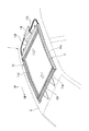
図1は、この実施形態のサンシェード装置10を車両1のルーフ部2の上方側(車室外部側)から見た斜視図であり、図2は、サンシェード装置10を車室内部側から見た斜視図である。
11は、車両1のルーフ部2の図示しないサンルーフ開口(開口部)の縁部に車室内部側から取り付けられるサンシェード装置10の矩形状の装置フレームである。装置フレーム11は、車両1の前後方向に沿って設置され、車両前方側の前部フレーム部11aと車両後方側の後部フレーム部11bには巻取装置12A,12Bがそれぞれ設置されている。Hereinafter, an embodiment according to the present invention will be described with reference to the drawings. In the following description, unless otherwise specified, “front”, “rear”, “upper” and “lower” mean “front”, “rear”, “upper” and “lower” when the vehicle is mounted. And In the figure, an arrow FR indicates the front of the vehicle 1 and an arrow UP indicates the upper side of the vehicle 1.
FIG. 1 is a perspective view of the
各巻取装置12A,12Bは、車幅方向に沿って延出するケース(符号省略)内に布等のシート状のシェード部材13A,13Bが引き出し可能に巻き取られている。車体前部側の巻取装置12Aからはシェード部材13Aが後方側に向かって引き出され、車体後部側の巻取装置12Bからはシェード部材13Bが前方側に向かって引き出される。各シェード部材13A,13Bは、引き出し方向の基端が巻取装置12A,12Bの各ケース内に巻取り方向にばね付勢されるとともに、引き出し方向の先端(「引き出し端」と呼ぶ。)側が装置フレーム11の左右両側の側部フレーム部11c,11dにスライド変位可能に保持されている。また、各シェード部材13A,13Bの引き出し端は、電動モータ14(駆動アクチュエータ)の動力によって引き出し方向前後に駆動操作されるようになっている。両シェード部材13A,13Bは、図2に示すように、引き出し端が装置フレーム11の前後方向の中央位置まで引き出され、それによって車両1のサンルーフ開口を車室内部側から閉塞する。
In each of the winding
図3は、サンシェード装置10のシェード閉時における図2のA−A断面に対応する断面図である。
同図に示すように、両シェード部材13A,13Bの引き出し端には、その端縁に沿って(なお、本明細書において、シェード部材の「端縁に沿って」とは、シェード部材の「引き出し方向と直交する方向に沿って」を意味するものとする。)アルミニウム合金製の長尺な骨格部材15A,15Bが設けられている。骨格部材15A,15Bは長手方向に亙ってほぼ一定断面に形成され、後部側の骨格部材15Bには、シェード閉時に、前後のシェード部材13A,13Bの引き出し端の間を閉塞するためのゴム製のシール部材30が取り付けられている。また、骨格部材15A,15Bの長手方向の両端部は、装置フレーム11の側部フレーム部11c,11dにスライド可能に保持されるとともに、電動モータ14の動力を伝達する図示しない動力伝達機構に連結されている。FIG. 3 is a cross-sectional view corresponding to the AA cross section of FIG. 2 when the shade of the
As shown in the drawing, the shade ends of the
図4は、シール部材30の図3と同様の断面図であり、図5,図6は、前部側と後部側の各骨格部材15A,15Bの図3と同様の断面図である。
図3及び図5に示すように、前部側の骨格部材15Aは、主に断面の潰れ方向の剛性維持と長手方向の曲げ剛性の維持を担う中空断面部16と、中空断面部16の車室内部側(図2中下側)に連設されたシェード保持部17と、中空断面部16とシェード保持部17の間に設けられ後部側のシェード部材13Bに臨むように開口する溝部18と、を備えている。4 is a cross-sectional view similar to FIG. 3 of the
As shown in FIGS. 3 and 5, the skeleton member 15 </ b> A on the front side mainly includes a hollow
中空断面部16は、略方形状の中空断面に形成され、後部側のシェード部材13Bに臨む後方側の面が、シェード閉時にシール部材30の当接する当接面16aとされている。
シェード保持部17は、コ字状の断面形状に形成され、その上壁17aの先端部が中空断面部16の下壁16bに接続されている。シェード保持部17は、その後壁17bの外側面29が後部側のシェード部材13Bに臨み、下壁17cの下面28が車室内に臨むようになっている。
溝部18は、シェード保持部17の上壁17aと中空断面部16の下壁16bの間に設けられている。溝部18は、開口側の領域が上壁17aと下壁16bによって略平行なスリット状に形成されるとともに、底部側の領域には開口側のスリット形状と略直交する長孔状の拡幅部19が設けられている。The
The
The
前部側のシェード部材13Aの引き出し端側の縁部は、図3に示すように、シェード保持部17の下面28と外側面29とを外側から包み込み、その状態において、端末部が溝部18内に挿入されてシェード保持部17に係止されている。具体的には、シェード部材13Aの引き出し端側の端末部には袋状に縫製された筒状部20が設けられ、端末部を溝部18に挿入した状態において、拡幅部19内で筒状部20に芯棒21を挿入することにより、端末部が溝部18内に抜け止めされている。
また、シール部材30が当接する中空断面部16の後方側の当接面16aは、シェード保持部17の外側面29に対して面一に形成されているのではなく、外側面29に対して前方側に(後部側のシェード部材13Bから離間する方向に)所定距離dだけオフセットして形成されている。As shown in FIG. 3, the edge portion on the drawer end side of the
Further, the abutting
一方、後部側の骨格部材15Bは、図3及び図6に示すように、主に断面の潰れ方向の剛性維持と長手方向の曲げ剛性の維持を担う中空断面部22(第2の中空断面部)と、中空断面部22の車室内部側(図2中下側)に設けられたシェード保持部23と、中空断面部22とシェード保持部23の間に設けられ前部側のシェード部材13Aに臨むように開口する凹形状部24と、凹形状部24とシェード保持部23とに隣接して設けられ前部側のシェード部材13Aに臨むように開口する溝部25と、を備えている。
On the other hand, as shown in FIGS. 3 and 6, the
中空断面部22は、前部側の骨格部材15Aの中空断面部16と同様の略方形状の基本形状に対して、前部の壁の一部を凹状に窪ませている。これにより中空断面部22は略L字形状となっている。凹形状部24は、前記の凹状に窪ませた部分によって形成されている。凹形状部24は、シール部材30を保持する部分であり、その上壁24aの一部には、シール部材30の抜けを規制する係止突起26が設けられている。
シェード保持部23は、前部側の骨格部材15Aと同様に、コ字状の断面形状に形成され、その上壁23aの先端部が中空断面部22の下端に接続されている。シェード保持部23は、その前壁23bの外側面31が前部側のシェード部材13Aに臨み、下壁23cの下面32が車室内に臨むようになっている。
溝部25は、シェード保持部23の上壁23aと凹形状部24の下壁24bの間に設けられている。溝部25は、開口側の領域が上壁23aと下壁24bによって略平行なスリット状に形成されるとともに、底部側の領域には開口側のスリット形状と略直交する長孔状の拡幅部33が設けられている。The
The
The
後部側のシェード部材13Bの引き出し端側の縁部は、図3に示すように、シェード保持部23の下面32と外側面31とを外側から包み込み、その状態において、端末部が溝部25内に挿入されてシェード保持部23に係止されている。この部分の具体的な係止は、前述した前部側のシェード部材13Aの場合と同様となっている。
As shown in FIG. 3, the edge portion on the drawer end side of the
また、シール部材30は、図3及び図4に示すように、後部側の骨格部材15Bの凹形状部24に嵌合固定される取付基部35と、取付基部35に連設され、シェード閉時に先端領域が前部側の骨格部材15Aの中空断面部16に当接する中空リップ部36とを備えている。取付基部35は硬質ゴムによって形成され、中空リップ部36は、取付基部35との連接部以外の主要な部分が軟質のスポンジゴムによって形成されている。
Further, as shown in FIGS. 3 and 4, the
取付基部35は、その上面側に係合溝37が設けられ、骨格部材15Bの凹形状部24に嵌入されたときに、凹形状部24側の係止突起26が係合溝37と係合されるようになっている。
また、中空リップ部36は、取付基部35が後部側の骨格部材15Bに固定された状態において、その先端側が前部側のシェード部材13A方向に向かって略三角形状に突出している。以下、中空リップ部36の延出端に向かって収斂する車室内部側と車室外部側の壁をそれぞれ室内壁38と室外壁39と呼ぶものとする。
室内壁38と室外壁39には、取付基部35からシェード引出方向に向かうにつれて車室内部側に傾斜する第1傾斜面38a,39aと、第1傾斜面38a,39aの先端部からシェード引出方向に向かうにつれて車室外部側に傾斜する第2傾斜面38b,39bとが形成され、第1傾斜面38a,39aと第2傾斜面38b,39bの間には車室内部側に凸状に屈曲する屈曲部38c,39cが設けられている。An
Further, the
The
第1傾斜面38a,39aと第2傾斜面38b,39bのシェード引き出し方向(車体前後方向)の長さL1,L2は、図4に示すように、第2傾斜面38b,39bの長さL2の方が第1傾斜面38a,39aの長さL1よりも長くなっている。なお、第1傾斜面38a,39aと第2傾斜面38b,39bは、同図に示すように、各延出方向の長さについても、第2傾斜面38b,39bの方が第1傾斜面38a,39aよりも長くなっている。
また、車室内に臨む室内壁38の外表面には、図4に示すように、シェード部材13A,13Bと同色の表皮部材40が被着されている。As shown in FIG. 4, the lengths L2 and L2 of the second
Further, as shown in FIG. 4, a
以上の構成において、図1に示すように、前後のシェード部材13A,13Bが開いた状態から、電動モータ14の動力が各シェード部材13A,13Bの引き出し端に伝達されると、両シェード部材13A,13Bが引き出し端を相互に突き合わせる方向に引き出されるようになる。
こうして両シェード部材13A,13Bの引き出し端が接近すると、図3に示すように後部側の骨格部材15Bに取り付けられたシール部材30が前部側の骨格部材15Aの中空断面部16に当接する。In the above configuration, as shown in FIG. 1, when the power of the
When the drawer ends of the
具体的には、最初にシール部材30の中空リップ部36(第2傾斜面38b,39b)の先端が前部側の骨格部材15Aの中空断面部16の当接面16aに接触し、両シェード部材13A,13Bの近接に伴って中空リップ部36に引き出し方向に沿った圧縮荷重が作用するようになる。これにより、中空リップ部36は、屈曲部38c,39cを基点として車室内部側に弾性変形し、中空断面部16に対する接触面積を増大させる。こうして、両シェード部材13A,13Bが終端位置まで閉じられると、第2傾斜面38bが車幅方向の全域にて中空断面部16の当接面16aに密接するとともに、中空リップ部36の室内壁38の屈曲部38cが前部側のシェード部材13Aと後部側のシェード部材13Bの間の隙間に凸状に迫り出す。
この結果、前後のシェード部材13A,13Bの間がシール部材30を介して閉塞される。Specifically, first, the tip of the hollow lip portion 36 (second inclined
As a result, the front and rear shade members 13 </ b> A and 13 </ b> B are closed via the
以下、この実施形態のサンシェード装置10によって得られる効果について説明する。
このサンシェード装置10は、前部側のシェード部材13Aの引き出し端側の骨格部材15Aに、引き出し端の端縁に沿う中空断面部16が設けられ、後部側のシェード部材13Bのシール部材30が、シェード閉時に中空断面部16の当接面16aに当接する基本構成とされているため、中空断面部16によって前部側のシェード部材13Aの引き出し端側の剛性を充分に高めることができるうえ、柔軟なシール部材30の先端領域を剛性の高い中空断面部16に安定的に密接させることができる。
したがって、このサンシェード装置10においては、シェード閉時に、骨格部材15Aが装置フレーム11の中央に位置され、車室内の乗員が骨格部材15Aに接触することがあっても、シェード部材13Aの引き出し端側の変形を抑制することができ、しかも、シール部材30が不規則に変形することによる外観品質の低下や、シール部での遮光性の低下(光の漏れ)も防止することができる。Hereinafter, effects obtained by the
In the
Accordingly, in this
また、この実施形態では、後部側のシェード部材13Bの骨格部材15Bにも、引き出し端の短縁に沿うように中空断面部22が設けられているため、シェード閉時における骨格部材13A,13Bの外力による変形を有効に防止することができるとともに、後部側の骨格部材15Bにおいてシール部材30のシール反力を安定的に受け止めることができる。
Further, in this embodiment, the
また、特に、この実施形態のように前後のシェード部材13A,13Bが電動モータ14(アクチュエータ)によって自動操作されるものにおいては、各シェード部材を個々に手動操作するタイプのものに比較して、両シェード部材13A,13B間に隙間のバラツキが大きくなり易い傾向にあるが、骨格部材15A,15Bに端縁に沿うように中空断面部16,22を設け、シェード閉時に、一方の骨格部材15Bのシール部材30を他方の骨格部材15Aの中空断面部16に当接させる本構造を採用した場合には、両シェード部材13A,13B間の隙間のバラツキに起因する不具合を有効に解消することができる。
In particular, in the case where the front and
即ち、前後のシェード部材13A,13Bをアクチュエータによって自動操作する場合には、両シェード部材13A,13Bが連動作動することになるため、シェード部材13A,13Bの個々のバラツキがシェード部材13A,13Bの作動時に重ね合わせられて現れる。このため、シェード閉時におけるシェード部材13A,13Bの間の隙間のバラツキはより大きくなる傾向となる。
この実施形態のサンシェード装置10においては、上記の構成を採用することにより、シェード閉時に、シール部材30を他方の骨格部材15Aの中空断面部16に安定的に当接させることができるため、シェード部材13A,13B間の隙間にある程度のバラツキがあっても、そのバラツキによる外観品質の低下やシール部での遮光性の低下を有効に防止することができ、さらに、シェード部材13A,13B間の異物の挟み込みを検知する検知装置を設けたときに、全閉間際で挟み込みが検知できない場合において、中空リップ部36にある程度の撓み代を確保しておくことで、異物及びサンシェード装置10の損傷を低減することができる。That is, when the front and
In the
また、このサンシェード装置10において、前後の骨格部材15A,15Bの中空断面部16,22の車室内部側にそれぞれシェード保持部17,23が配置され、シェード保持部17,23の外側面29,31と下面28,32とがそれぞれシェード部材13A,13Bによって覆われるようになっているため、シェード閉時に、骨格部材15A,15Bをシェード部材13A,13Bによって車室内部側から覆い隠し、見栄えを良好にすることができる。
そして、このサンシェード装置10では、シェード閉時に、シール部材30と当接する前部側の骨格部材15Aの中空断面部16がシェード保持部17の車室外部側(上方側)に配置されているため、シール部材30との当接部(光の漏れる可能性の高くなる部位)を車室内部側から見えにくくすることができるとともに、シェード閉時に、シール部材30がシェード部材13Aに直接当接することによってシェード部材13Aに皺が発生するのを抑制することができる。Further, in the
In the
さらに、この実施形態の場合、前部側の骨格部材15Aは、中空断面部16の当接面16aが、シェード保持部17の外側面29よりも前方側に(後部側のシェード部材13Bから離間する方向に)所定距離dだけオフセットして形成されているため、シェード閉時に、車室内部側からシール部材30との当接部をより見えにくくすることができる。そして、この実施形態では、中空断面部16の当接面16aがシェード保持部17の外側面29よりも、後部側のシェード部材13Bから離間する位置に配置されていることから、シェード閉時に、シール部材30の過度の撓みを抑制しつつ、シェード部材13A,13Bの引き出し端同士を充分に近接させることができる。
したがって、シェード閉時における充分な遮光性を確保しつつ、車室内部側からの外観品質を高めることができる。Further, in the case of this embodiment, the
Therefore, it is possible to improve the appearance quality from the vehicle interior side while ensuring sufficient light shielding properties when the shade is closed.
さらに、この実施形態のサンシェード装置10では、前部側の骨格部材15Aのうちの中空断面部16と隣接する部位に後方側に開口する溝部18が設けられ、シェード部材13Aの引き出し端がこの溝部18に係止されているため、溝部18内において剛性の高い中空断面部16の壁の一部でシェード部材13Aの引き出し端を確実に保持することができる。
また、この実施形態では、シェード部材13Aの引き出し端を溝部18に差し込んで係止させるため、シェード保持部17の外側面29から上壁17aに亙る部位がシェード部材13Aによって覆われることになる。このため、骨格部材15Aは車室内部側からより見えにくくなる。Furthermore, in the
Further, in this embodiment, since the drawer end of the
また、このサンシェード装置10のシール部材30は、取付基部35側からシェード引出方向に向かうにつれて車室内部側に傾斜する第1傾斜面38a,39aと、第1傾斜面38a,39aの先端部からシェード引出方向に向かうにつれて車室外部側に傾斜する第2傾斜面38b,39bと、を備え、第2傾斜面38bの先端側が前部側の骨格部材15Aの中空断面部16に当接するようになっているため、シェード閉時に、屈曲部38c,39cを基点として中空リップ部36が車室内部側に凸となるように変形し、それによって前後のシェード部材13A,13B間の隙間を段差なく塞ぐことができる。したがって、これにより車室内部側からの外観品質を高めることができる。
In addition, the
さらに、シール部材30は、先端側の第2傾斜面38b,39bの方が基端側の第1傾斜面38a,39aよりも延出長さが長くなるように形成されているため、シェード閉時に、先端側の第2傾斜面38b,39bを前部側の骨格部材15Aの中空断面部16に柔軟に追従させ、遮光性をより高めることができる。
そして、シール部材30は、第1傾斜面38a,39aと第2傾斜面38b,39bの前記の延出長さの関係から、シェード閉時に、シール部材30が変形した後には、第1傾斜面38a,39aと第2傾斜面38b,39bの間の屈曲部38c,39cが前後のシェード部材13A,13Bの中間位置に配置されることになる。このため、車室内から見たときに屈曲部38cの迫り出し部分が両シェード部材13A,13Bの隙間位置と合致し、外観品質がより高まる。Furthermore, since the
Then, due to the relationship between the extended lengths of the first
また、この実施形態のシール部材30は、先端部側に車室外部側方向に傾斜する第2傾斜面38b,39bが設けられているため、シェード閉時に、シール部材30の先端側が前部側のシェード部材13Aに強く圧接されるのを抑制することができる。したがって、シェード部材13Aの皺の発生を未然に防止することができる。
Moreover, since the sealing
また、このサンシェード装置10においては、後部側の骨格部材15Bの中空断面部22と隣接する部位に、前方側に開口する凹形状部24が設けられ、その凹形状部24内にシール部材30の取付基部35が保持されているため、中空断面部22によって骨格部材15Bの剛性を高めつつ、剛性の高い中空断面部22の壁の一部でシール部材35を確実に保持することができる。
さらに、この実施形態の場合、凹形状部24は中空断面部22の壁の一部を内側方向に窪ませて形成されているため、骨格部材15Bの外形を前部側の骨格部材15Aとほぼ同じサイズに抑えたまま、シール部材30に対する充分な保持剛性を確保することができる。Further, in the
Furthermore, in the case of this embodiment, the
なお、この発明は上記の実施形態に限定されるものではなく、その要旨を逸脱しない範囲で種々の設計変更が可能である。
例えば、上記の実施形態は、一対のシェード部材が車両のルーフ部において、車体前後方向にスライド作動するサンシェード装置であったが、一対のシェード部材は車両のルーフ部で車幅方向左右にスライド作動するものであっても良い。また、サンシェード装置の設置部位も車両のルーフ部に限らず、車両の側部や後部の窓開口等であっても良い。この場合、一対のシェード部材のスライド作動方向は上下方向であっても良い。In addition, this invention is not limited to said embodiment, A various design change is possible in the range which does not deviate from the summary.
For example, in the above-described embodiment, the pair of shade members is a sunshade device that slides in the vehicle front-rear direction in the vehicle roof portion. However, the pair of shade members slides in the vehicle width direction left and right in the vehicle roof portion. It may be what you do. Further, the installation site of the sunshade device is not limited to the roof portion of the vehicle, and may be a window opening on the side portion or the rear portion of the vehicle. In this case, the sliding operation direction of the pair of shade members may be the vertical direction.
10…サンシェード装置
12A,12B…巻取装置
13A,13B…シェード部材
15A,15B…骨格部材
16…中空断面部
16a…当接面
17…シェード保持部
18…溝部
22…中空断面部(第2の中空断面部)
24…凹形状部
30…シール部材
31…外側面(一方のシェード部材に臨む面)
32…下面(車室内に臨む面)
35…取付基部
38a,39a…第1傾斜面
38b,39b…第2傾斜面DESCRIPTION OF
24 ...
32 ... Lower surface (surface facing the passenger compartment)
35 ... Mounting
Claims (7)
互いに離間して配置される一対の巻取装置と、
前記各巻取装置に引き出し可能に巻き取られるシート状のシェード部材と、
前記各シェード部材の引き出し端に、その端縁に沿うように設けられた骨格部材と、
前記両シェード部材の前記引き出し端を前記車両の開口部の略中央で相互に近接させるシェード閉時に、一方の前記シェード部材の前記引き出し端と他方の前記シェード部材の前記引き出し端の間を覆うシール部材と、
を備え、
前記一方のシェード部材の前記引き出し端側には、その端縁に沿うように前記シール部材が設けられ、
前記他方のシェード部材の前記骨格部材には、前記他方のシェード部材の前記引き出し端の端縁に沿って延出する中空断面部が設けられ、
前記シール部材は、前記シェード閉時に、前記他方のシェード部材の前記骨格部材の前記中空断面部に当接し、
前記他方のシェード部材の前記骨格部材には、前記他方のシェード部材の前記引き出し端側の端縁を保持するシェード保持部が前記中空断面部の車室内部側に設けられ、
前記シェード保持部は、前記車室内部に臨む面と前記一方のシェード部材に臨む面を前記他方のシェード部材によって覆われ、
前記他方のシェード部材の前記一方のシェード部材に臨む面は、前記一方のシェード部材から隙間を介して離間し、
前記シール部材は、前記隙間を閉塞することを特徴とするサンシェード装置。 A sunshade device provided at an opening of a vehicle,
A pair of winding devices that are spaced apart from each other;
A sheet-like shade member that is wound so as to be able to be pulled out by each of the winding devices;
A skeleton member provided at the drawer end of each shade member along the edge;
A seal that covers the space between the drawer end of one of the shade members and the drawer end of the other shade member when the shade is closed so that the drawer ends of the shade members are close to each other at the approximate center of the opening of the vehicle. Members,
With
On the drawer end side of the one shade member, the seal member is provided along the edge thereof,
The skeleton member of the other shade member is provided with a hollow cross-sectional portion extending along an edge of the drawer end of the other shade member,
The seal member abuts on the hollow cross-section of the skeleton member of the other shade member when the shade is closed;
The skeleton member of the other shade member is provided with a shade holding portion that holds an end edge of the other shade member on the drawer end side on the vehicle interior side of the hollow cross-section portion,
The shade holding part is covered with the other shade member on the surface facing the vehicle interior and the surface facing the one shade member,
The surface facing the one shade member of the other shade member is separated from the one shade member via a gap,
The sunshade device, wherein the seal member closes the gap.
前記他方のシェード部材の前記引き出し端は前記溝部に係止されていることを特徴とする請求項1または2に記載のサンシェード装置。The sunshade device according to claim 1 or 2, wherein the lead-out end of the other shade member is locked to the groove.
前記第2傾斜面の先端側が前記他方のシェード部材の前記中空断面部に当接することを特徴とする請求項1〜3のいずれか1項に記載のサンシェード装置。The sunshade device according to any one of claims 1 to 3, wherein a tip end side of the second inclined surface is in contact with the hollow cross-sectional portion of the other shade member.
前記凹形状部は、当該凹形状部に隣接する前記第2の中空断面部の壁を当該第2の中空断面部の内側方向に窪ませて形成され、The concave shape portion is formed by recessing the wall of the second hollow cross-section portion adjacent to the concave shape portion in the inner direction of the second hollow cross-section portion,
前記シール部材は、前記凹形状部に保持されていることを特徴とする請求項1〜5のいずれか1項に記載のサンシェード装置。The sunshade device according to claim 1, wherein the seal member is held by the concave portion.
前記一方のシェード部材の前記骨格部材には、前記一方のシェード部材の前記引き出し端側の端縁を保持する第2のシェード保持部が前記第2の中空断面部の車室内部側に設けられ、The skeleton member of the one shade member is provided with a second shade holding portion for holding an edge of the one shade member on the drawer end side on the vehicle interior side of the second hollow cross-sectional portion. ,
前記第2のシェード保持部は、前記車室内部に臨む面と前記他方のシェード部材に臨む面を前記一方のシェード部材によって覆われ、The second shade holding part is covered with the one shade member on the surface facing the vehicle interior and the surface facing the other shade member,
前記他方のシェード部材の前記一方のシェード部材に臨む面は、前記一方のシェード部材の前記他方のシェード部材に臨む面から隙間を介して離間していることを特徴とする請求項1に記載のサンシェード装置。The surface of the other shade member facing the one shade member is spaced apart from the surface of the one shade member facing the other shade member via a gap. Sunshade device.
Priority Applications (1)
| Application Number | Priority Date | Filing Date | Title |
|---|---|---|---|
| JP2013533619A JP5638145B2 (en) | 2011-09-12 | 2012-09-04 | Sunshade equipment |
Applications Claiming Priority (4)
| Application Number | Priority Date | Filing Date | Title |
|---|---|---|---|
| JP2011198318 | 2011-09-12 | ||
| JP2011198318 | 2011-09-12 | ||
| JP2013533619A JP5638145B2 (en) | 2011-09-12 | 2012-09-04 | Sunshade equipment |
| PCT/JP2012/072447 WO2013038951A1 (en) | 2011-09-12 | 2012-09-04 | Sunshade device |
Publications (2)
| Publication Number | Publication Date |
|---|---|
| JP5638145B2 true JP5638145B2 (en) | 2014-12-10 |
| JPWO2013038951A1 JPWO2013038951A1 (en) | 2015-03-26 |
Family
ID=47883182
Family Applications (1)
| Application Number | Title | Priority Date | Filing Date |
|---|---|---|---|
| JP2013533619A Expired - Fee Related JP5638145B2 (en) | 2011-09-12 | 2012-09-04 | Sunshade equipment |
Country Status (6)
| Country | Link |
|---|---|
| US (1) | US9073415B2 (en) |
| EP (1) | EP2759427B1 (en) |
| JP (1) | JP5638145B2 (en) |
| CN (1) | CN103796855B (en) |
| IN (1) | IN2014CN02609A (en) |
| WO (1) | WO2013038951A1 (en) |
Families Citing this family (5)
| Publication number | Priority date | Publication date | Assignee | Title |
|---|---|---|---|---|
| JPWO2015178244A1 (en) * | 2014-05-22 | 2017-04-20 | 八千代工業株式会社 | Roll sunshade equipment |
| CN107669081B (en) * | 2017-11-09 | 2022-09-13 | 上海耀皮康桥汽车玻璃有限公司 | Pull plate shading structure for sun-shading curtain |
| JP6846461B2 (en) * | 2019-05-31 | 2021-03-24 | 本田技研工業株式会社 | Cowl top structure |
| CN111105711B (en) * | 2019-11-28 | 2021-05-18 | 联想(北京)有限公司 | Electronic equipment |
| USD1001702S1 (en) * | 2023-06-20 | 2023-10-17 | Yongfu Li | Sunshade |
Citations (6)
| Publication number | Priority date | Publication date | Assignee | Title |
|---|---|---|---|---|
| JPS60259525A (en) * | 1984-06-05 | 1985-12-21 | Kinugawa Rubber Ind Co Ltd | Weather strip for sun roof |
| JPS63156853U (en) * | 1987-04-03 | 1988-10-14 | ||
| EP0735229A1 (en) * | 1995-04-01 | 1996-10-02 | Polyplastic B.V. | Roller blind unit |
| JP2002054369A (en) * | 2000-05-10 | 2002-02-20 | Webasto Japan Kk | Roller blind device |
| JP2008265413A (en) * | 2007-04-17 | 2008-11-06 | Toyota Boshoku Corp | Sunshade device |
| JP2009101728A (en) * | 2007-10-19 | 2009-05-14 | Toyota Industries Corp | Roof shade device for automobile |
Family Cites Families (7)
| Publication number | Priority date | Publication date | Assignee | Title |
|---|---|---|---|---|
| JPS61110424A (en) | 1984-11-05 | 1986-05-28 | Canon Inc | Formation of deposited film |
| JPS61110424U (en) | 1984-12-26 | 1986-07-12 | ||
| JPS63156853A (en) | 1986-12-19 | 1988-06-29 | Kuraray Co Ltd | Resin composition |
| JP2946734B2 (en) | 1990-11-02 | 1999-09-06 | キヤノン株式会社 | Fixing device |
| JP4171473B2 (en) | 2005-03-22 | 2008-10-22 | 本田技研工業株式会社 | Sunshade equipment |
| JP2007168701A (en) * | 2005-12-26 | 2007-07-05 | Toyota Boshoku Corp | Vehicular sun shade device |
| US8814258B2 (en) * | 2008-08-15 | 2014-08-26 | Ford Global Technologies, Llc | Panoramic vehicle roof module assemblies |
-
2012
- 2012-09-04 US US14/343,225 patent/US9073415B2/en active Active
- 2012-09-04 WO PCT/JP2012/072447 patent/WO2013038951A1/en active Application Filing
- 2012-09-04 CN CN201280044429.XA patent/CN103796855B/en active Active
- 2012-09-04 JP JP2013533619A patent/JP5638145B2/en not_active Expired - Fee Related
- 2012-09-04 EP EP12831854.0A patent/EP2759427B1/en not_active Not-in-force
- 2012-09-04 IN IN2609CHN2014 patent/IN2014CN02609A/en unknown
Patent Citations (6)
| Publication number | Priority date | Publication date | Assignee | Title |
|---|---|---|---|---|
| JPS60259525A (en) * | 1984-06-05 | 1985-12-21 | Kinugawa Rubber Ind Co Ltd | Weather strip for sun roof |
| JPS63156853U (en) * | 1987-04-03 | 1988-10-14 | ||
| EP0735229A1 (en) * | 1995-04-01 | 1996-10-02 | Polyplastic B.V. | Roller blind unit |
| JP2002054369A (en) * | 2000-05-10 | 2002-02-20 | Webasto Japan Kk | Roller blind device |
| JP2008265413A (en) * | 2007-04-17 | 2008-11-06 | Toyota Boshoku Corp | Sunshade device |
| JP2009101728A (en) * | 2007-10-19 | 2009-05-14 | Toyota Industries Corp | Roof shade device for automobile |
Also Published As
| Publication number | Publication date |
|---|---|
| EP2759427A1 (en) | 2014-07-30 |
| JPWO2013038951A1 (en) | 2015-03-26 |
| EP2759427B1 (en) | 2017-03-01 |
| IN2014CN02609A (en) | 2015-06-26 |
| CN103796855A (en) | 2014-05-14 |
| EP2759427A4 (en) | 2015-05-27 |
| WO2013038951A1 (en) | 2013-03-21 |
| CN103796855B (en) | 2016-07-06 |
| US20140224438A1 (en) | 2014-08-14 |
| US9073415B2 (en) | 2015-07-07 |
Similar Documents
| Publication | Publication Date | Title |
|---|---|---|
| JP5638145B2 (en) | Sunshade equipment | |
| US20140132025A1 (en) | Interior component for vehicle | |
| US20070068638A1 (en) | Anti-wind buffeting device for an automobile | |
| US8002342B2 (en) | Blind cover positioning structure | |
| US7857372B2 (en) | Tonneau cover apparatus for an automobile | |
| KR101219396B1 (en) | Interlock type roll blind apparatus of panorama sunroof | |
| JP4919083B2 (en) | Sunshade equipment | |
| EP3676116B1 (en) | Shade roller apparatus | |
| US20170225549A1 (en) | Roller sunshade device | |
| JP5849450B2 (en) | Sunshade equipment | |
| CN111051098B (en) | Shielding shutter device | |
| JP2013216124A (en) | Roll shade device | |
| JP6669904B2 (en) | Sunroof equipment | |
| WO2016035456A1 (en) | Deflector structure for sunroof device | |
| JP6919465B2 (en) | Frame garnish assembly structure | |
| JP2007290609A (en) | Sun shade for automobile window glass | |
| JP2010100266A (en) | Sunshade device for vehicle | |
| CN104276017B (en) | Vapour window for automobile cover | |
| JP5098755B2 (en) | Car tonneau cover equipment | |
| JP2010162917A (en) | Vehicle body structure | |
| JP2010036590A (en) | Seal structure of frameless door | |
| JP2009241756A (en) | Tonneau cover device of automobile |
Legal Events
| Date | Code | Title | Description |
|---|---|---|---|
| TRDD | Decision of grant or rejection written | ||
| A01 | Written decision to grant a patent or to grant a registration (utility model) |
Free format text: JAPANESE INTERMEDIATE CODE: A01 Effective date: 20141007 |
|
| A61 | First payment of annual fees (during grant procedure) |
Free format text: JAPANESE INTERMEDIATE CODE: A61 Effective date: 20141021 |
|
| R150 | Certificate of patent or registration of utility model |
Ref document number: 5638145 Country of ref document: JP Free format text: JAPANESE INTERMEDIATE CODE: R150 |
|
| R250 | Receipt of annual fees |
Free format text: JAPANESE INTERMEDIATE CODE: R250 |
|
| LAPS | Cancellation because of no payment of annual fees |