JP5636041B2 - Pressure regulator - Google Patents
Pressure regulator Download PDFInfo
- Publication number
- JP5636041B2 JP5636041B2 JP2012507459A JP2012507459A JP5636041B2 JP 5636041 B2 JP5636041 B2 JP 5636041B2 JP 2012507459 A JP2012507459 A JP 2012507459A JP 2012507459 A JP2012507459 A JP 2012507459A JP 5636041 B2 JP5636041 B2 JP 5636041B2
- Authority
- JP
- Japan
- Prior art keywords
- control member
- valve seat
- mounting assembly
- seat
- sleeve
- Prior art date
- Legal status (The legal status is an assumption and is not a legal conclusion. Google has not performed a legal analysis and makes no representation as to the accuracy of the status listed.)
- Active
Links
Images


Classifications
-
- G—PHYSICS
- G05—CONTROLLING; REGULATING
- G05D—SYSTEMS FOR CONTROLLING OR REGULATING NON-ELECTRIC VARIABLES
- G05D16/00—Control of fluid pressure
- G05D16/04—Control of fluid pressure without auxiliary power
- G05D16/06—Control of fluid pressure without auxiliary power the sensing element being a flexible membrane, yielding to pressure, e.g. diaphragm, bellows, capsule
- G05D16/063—Control of fluid pressure without auxiliary power the sensing element being a flexible membrane, yielding to pressure, e.g. diaphragm, bellows, capsule the sensing element being a membrane
- G05D16/0644—Control of fluid pressure without auxiliary power the sensing element being a flexible membrane, yielding to pressure, e.g. diaphragm, bellows, capsule the sensing element being a membrane the membrane acting directly on the obturator
- G05D16/0655—Control of fluid pressure without auxiliary power the sensing element being a flexible membrane, yielding to pressure, e.g. diaphragm, bellows, capsule the sensing element being a membrane the membrane acting directly on the obturator using one spring-loaded membrane
- G05D16/0661—Control of fluid pressure without auxiliary power the sensing element being a flexible membrane, yielding to pressure, e.g. diaphragm, bellows, capsule the sensing element being a membrane the membrane acting directly on the obturator using one spring-loaded membrane characterised by the loading mechanisms of the membrane
Description
本発明は、全般的には流体制御装置に関し、より具体的には、流体制御装置のための杯状座部設計に関する。 The present invention relates generally to fluid control devices, and more particularly to cup seat designs for fluid control devices.
流体制御装置は、制御弁および調節器を含む、様々な分類の機器を含む。そうした制御装置は、通過する流体の流れを制御するために、化学処理システム、天然ガス供給システム等のような流体プロセス制御システム内部に結合するために適合される。各制御装置は流体流路を画定し、かつ、その流路の寸法を調整するための制御部材を含む。たとえば、図1は、弁本体12および駆動器14を含む既知の調節器アセンブリ10を示す。弁本体12は流路16を画定し、かつ、のど部18を含む。図1において、調節器アセンブリ10は上昇流構成とされている。駆動器14は、上部駆動器筐体20、下部駆動器筐体22、ダイヤフラム32を含むダイヤフラムサブアセンブリ30および制御部材24を含む。
Fluid control devices include various classes of equipment, including control valves and regulators. Such a controller is adapted for coupling within a fluid process control system, such as a chemical processing system, a natural gas supply system, etc., to control the flow of fluid through it. Each control device defines a fluid flow path and includes a control member for adjusting the dimensions of the flow path. For example, FIG. 1 shows a known
制御部材24は、上部駆動器筐体20および下部駆動器筐体22の内部に配置され、かつ、ダイヤフラムサブアセンブリ30の両側の圧力の変化に応じた双方向の変位のために適合される。そのように構成され、制御部24はのど部18を通過する流体の流れを制御する。図示するように、および、ほとんどの適用において、制御部材24の下端に近接する表面は、調節器アセンブリ10が開放位置にあるときにそこを通って流体流が通過する、概して凸型の表面を有する。さらに、図示するように、調節器アセンブリ10は、弁本体12ののど部18に配置されるシートリング26を含む。弁本体12の出口圧力が高い場合、制御部材24の封止面28がシートリング26と封止係合し、のど部18を閉鎖する場合がある。同様に、駆動器14にいかなる圧力も存在しない場合、またはダイヤフラム32が故障した場合、上部駆動器筐体20の環状空洞部36内部に配置されたコイルばね34が、制御部材24を閉鎖位置へと付勢する。このような調節器は、「故障時閉鎖」調節器として一般に知られている。
The
「故障時開放」調節器は、「故障時閉鎖」調節器と類似して作動するが、ダイヤフラムが故障した場合に、ばねが制御部材を、閉鎖位置ではなく、開放位置へと付勢する。例示的な「故障時開放」調節器は、参照によりその全体が本明細書中に明示的に組み込まれる、Roperらによる、“Positioning Device for Pressure Regulator”と題された、米国特許出願公開第2008/0078460A1号において例証され、説明される。Roperらにより教示された調節器において、制御部材24を開放位置に向かって付勢するために、ばねが制御部材24内部に備えられるか、または他の方法で制御部材24と結合される場合がある。ダイヤフラムまたは他の制御用構成要素が故障した場合、ばねが調節器アセンブリを開放するので、流体は途切れることなく、かつ、制御されずに、調節器を通過して流れ続ける。したがって、そのような構成の多くは、「故障時開放」調節器が故障した場合に流体流を制御する、監視調節器を含む。
The “Open on Failure” regulator operates similarly to the “Close on Failure” regulator, but if the diaphragm fails, the spring biases the control member to the open position rather than the closed position. An exemplary “open on failure” regulator is disclosed in US Patent Application Publication No. 2008, entitled “Positioning Device for Pressure Regulator” by Roper et al., Which is expressly incorporated herein by reference in its entirety. Illustrated and described in / 0078460A1. In the regulator taught by Roper et al., A spring may be provided within the
Roperらによって教示されるような「故障時開放」調節器において、「故障時開放」調節器が高圧力の状況に設置された場合に、運用上の問題が生じる場合があることが観察されてきた。入口圧力が高いと同時に出口圧力が低いとき、弁体に作用する付加的な不安定な力によって、調節器の制御および安定性の問題が生じる可能性がある。いくつかの例において、これらの力は、流体の下流の体積を増大させること(たとえば、下流の導管の直径を大きくすること)、並びに/または駆動器ダイヤフラム室への流れおよび駆動器ダイヤフラム室からの流れを制限することによって、最小化することが可能である。しかしながら、これらの矯正手段が実施された場合でさえ、流速が高いときには、弁体に作用する力の勾配が制御の問題をもたらすことで、制御の問題が時に再発する可能性がある。そのような高流速の用途においては、負の圧力勾配が生じる可能性があり、弁座の両側の圧力降下によって、ばねの力が負の圧力勾配によって生み出された力に打ち勝つまで、弁体がはじめに弁座に向かって引き寄せられ、駆動器が調節器の反応を制御するために動作するにしたがって、弁体は高周波振動のパターンに定着する場合がある。調節器システムの剛性の不足によって、この不安定な出力はそれ自体持続する場合がある。したがって、入口圧力が高く、出口圧力が低く、かつ高流速の設備において安定した出力を維持する、改善された「故障時開放」調節器の必要が存在する。 It has been observed that in an “open on failure” regulator as taught by Roper et al., Operational problems may arise when the “open on failure” regulator is installed in a high pressure situation. It was. When the inlet pressure is high and the outlet pressure is low, additional unstable forces acting on the valve body can cause regulator control and stability problems. In some examples, these forces increase the downstream volume of the fluid (eg, increase the diameter of the downstream conduit) and / or flow to and from the driver diaphragm chamber. Can be minimized by restricting the flow. However, even when these corrective measures are implemented, when the flow rate is high, the gradient of force acting on the valve body can cause control problems, which can sometimes cause the control problems to recur. In such high flow rate applications, a negative pressure gradient can occur, and the valve body will not move until the pressure drop across the valve seat overcomes the force created by the negative pressure gradient. The valve body may initially settle toward a high frequency vibration pattern as it is pulled toward the valve seat and the driver operates to control the regulator response. Due to the lack of rigidity of the regulator system, this unstable output may itself persist. Accordingly, there is a need for an improved “open on failure” regulator that maintains high power in high inlet pressure, low outlet pressure, and high flow rate equipment.
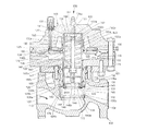
図2を参照すると、本開示の原理に従って構成された制御装置の一実施形態は、圧力調節器100を含む。圧力調節器100は、一般に、弁本体102、シートリング104および駆動器106を含む。後に検討するように、弁本体102は、入口110と出口112との間に延在し、加えて駆動器106内にも延在する、流路108を画定する。駆動器106は、図2に示すような開放位置と閉鎖位置(図示せず)との間で移動可能な制御アセンブリ114を含み、制御アセンブリ114はシートリング104に係合する。制御アセンブリ114の移動は、入口110および出口112における流体圧力の変動に対応して起こる。したがって、シートリング104に対する制御アセンブリ114の位置は、圧力調節器100の流量に影響を及ぼす。
With reference to FIG. 2, one embodiment of a controller configured in accordance with the principles of the present disclosure includes a
さらに、弁本体102は、入口110と出口112との間にのど部116を画定する。のど部116は、シートリング104を収容し、かつ、支持する段差部118を含む。一形態において、シートリング104とのど部116の段差部118との間にOリングが配置されてもよく、その間に液密封止を提供してもよい。
Further, the
上述のように、駆動器106は、制御アセンブリ114を含み、さらに、上部駆動器筐体122、下部駆動器筐体124および複数のピン126を含む。上部駆動器筐体122および下部駆動器筐体124は、少なくとも1つのねじ付き締結具119および対応するナット121によって、互いに固定される。上部駆動器筐体122は、中央開口123、第1制御入口125(破線で示す)およびトラベルチャンバ127を画定する。トラベルチャンバ127は、駆動器106内部の制御アセンブリ114の位置を指し示す、トラベルインジケータ131を含む。下部駆動器筐体124は、第2制御入口129を画定する。
As described above, the
上部駆動器筐体122および下部駆動器筐体124は共同して、中空の首部128を含む空洞135を画定する。中空の首部128は、弁本体102内の駆動器開口115内部に配置される。図2で確認されるように、複数のピン126は、中空の首部128に固定された第1端部126aおよび中空の首部128から離れて位置された第2端部126bを有する。図示する形態において、第1端部126aは、中空の首部128内に形成された内腔にねじ留めされる。第2端部126bは、シートリング104に係合する。したがって、ピン126およびのど部116の段差部118は、弁本体102内で、シートリング104を挟持し、軸上に位置させ、固定する。調節器100は、弁本体102に関して、シートリング104を位置調整する複数のピン126を含むものとして説明されてきたが、調節器100の代替の形態は、シートリング104を位置調整するためにのど部116内に配置されるケージを含む場合がある。別の形態では、シートリング104は弁本体102にねじ留めされ、接着され、または他の方法で固定されてもよい。
The upper driver housing 122 and the
続けて図2を参照すると、制御アセンブリ114は、中空スリーブ130、取り付けサブアセンブリ132、ダイヤフラムサブアセンブリ133および位置調整装置アセンブリ138のような制御部材を含む。スリーブ130は概して管状であり、概して円筒状の内部表面143および概して円筒状の外部表面147を画定する。内部表面143は、スリーブ130を通る中央内腔を画定する。さらに、スリーブ130は、上端130aと下端130bとを含む。上端130aは空洞135内部に配置され、下端130bは下部駆動器筐体124の中空首部128内部に配置される。スリーブ130の上端130aは開放されており、かつ、外部表面147上に形成された円周フランジ140を含む。さらに、スリーブ130の上部130aは、内部表面143上にねじ部141を含む。スリーブ130の下端130bは開放されており、かつ、取り付けサブアセンブリ132を収容する。
With continued reference to FIG. 2, the
図3および図4に最もよく示されるように、取り付けサブアセンブリ132は、取り付け部材またはスリーブアダプタ142、ディスクホルダー144および環状封止ディスクまたは成形座部146を含む。開示する形態において、スリーブアダプタ142は、スリーブ130の開放下端130bにねじ留めされた概して円筒状の本体を含み、座ぐり穴148を画定する。座ぐり穴148は、スリーブ130の陥凹底部表面を形成する。座ぐり穴148は、スリーブアダプタ142ののど部側に配置される大直径部148a、および中空スリーブ130の内側に開口する小直径部148bと共に、スリーブ130と概して軸方向に整列する。ディスクホルダー144は、1つまたは複数の締結具149によってスリーブアダプタ142に固定された、概して円筒状の本体を含み、かつ、その間に、封止装置を形成するためのOリング150を含んでもよい。図示された形態において、留め具149はねじ付き締結具を含む。ディスクホルダー144は、スリーブアダプタ142内の座ぐり穴148の大直径部148aの直径とほぼ等しい直径を有する貫通孔151を画定し、この貫通孔と共に軸方向に整列する。
As best shown in FIGS. 3 and 4, the mounting
図示するように、ディスクホルダー144は、中空スリーブ130の第2端部130bおよび/またはOリング150と係合する上面を有する、外側に延在するフランジ152をさらに含む場合がある。ディスクホルダー144の底面に、または、フランジ152が備えられる場合はその底面に、環状溝154が画定および配置され、かつ、その中に成形座部146を受容する。成形座部146は、弾性材料で作られ、ディスクホルダー144の溝154に固定される、概して輪状のディスクである。一形態において、成形座部146は、接着剤によってディスクホルダー144の溝154に固定される。制御アセンブリ114が図4に示すような閉鎖位置にあるとき、成形座部146がシートリング104に対して圧迫されるように、成形座部146および溝154はシートリング104の形状に対応するように構成される。
As shown, the
次に、図2に示す調節器100の上部を参照すると、ダイヤフラムサブアセンブリ133は、ダイヤフラム134、上部ダイヤフラムプレート136aおよび下部ダイヤフラムプレート136bを含む。上部ダイヤフラムプレート136aおよび下部ダイヤフラムプレート136bは、スリーブ130の円周フランジ140上で締め付けられる。ダイヤフラムプレート136a、136bは、締結具156を介して互いに固定され、それにより、スリーブ130とダイヤフラムプレート136a、136bを互いに固定する。さらに、ダイヤフラムプレート136a、136bは、ダイヤフラム134の半径方向内側部分を挟持する。ダイヤフラム134の半径方向外側部分は、上部駆動器筐体122と下部駆動器筐体124の間に固定される。
Referring now to the top of the
位置調整装置アセンブリ138は、最初にスリーブ130内部に配置され、スリーブ130を図2に示す開放位置へと付勢する。位置調整装置アセンブリ138は、一般に、中央ロッド186、第1ばね座188、第2ばね座190、ばね193のような付勢部材および保持プレート192を備える。中央ロッド186は、第1ねじ端部186aおよび第2ねじ端部186bを含む。第1ねじ端部186aは、上部駆動器筐体122の中央開口123を貫通して延在する。外部ナット194は第1ねじ端部186a上にねじ留めされ、図2に示す調節器100の配向に対して下方向の、中央ロッド186の軸方向変位を限定する。中間ナット196は、中央ロッド186の第1ねじ端部186a上に外部ナット194を越えてねじ留めされ、図2に示す調節器100の配向に対して上方向の、中央ロッド186の軸方向変位を限定する。したがって、中央ロッド186の第1ねじ端部186aは、上部駆動器筐体122に対する軸方向変位に対して効果的に固定され、第2ねじ端部186bは駆動器106内に延在する。
The
したがって、図示するように、中央ロッド186の第2ねじ端部186bはスリーブ130内に延在し、スリーブ130の第2端部130bに隣接して配置される。一対の保持ナット198a、198bは、中央ロッド186の第2ねじ端部186b上にねじ留めされる。保持ナット198a、198bは、第1ばね座188、ばね193および第2ばね座192を中央ロッド186上に支持する。以下でより詳細に検討するように、第1ばね座188は、スリーブ130内部に摺動可能に配置される。より具体的には、第1ばね座188は、保持ナット198a、198bと係合関係にある、概して円筒状のプレートを備える。したがって、ばね193は、保持プレート192に対して、およびスリーブ130に対して、第2ばね座190を固定する。さらに、第1ばね座188は中央ロッド186に対して固定され、中央開口188aおよび複数の開口部188bを画定する。中央開口188aは、保持ナット198a、198bと直接隣接して、中央ロッド186の第2端部186bを受容する。複数の開口部188bは、取り付けサブアセンブリ132の座ぐり穴148および貫通孔151と流体連通し、そしてそれ故に流路108と流体連通する。
Thus, as shown, the second threaded
同様に、第2ばね座190は、中央開口190aおよび複数の開口部190bを画定する、概して円筒状のプレートを備える。第2ばね座190の中央開口190aは、第1ねじ端部186a付近で中央ロッド186を受容する。複数の開口部190bは、第1ばね座188の複数の開口部188bと流体連通し、そしてそれ故に流路108と流体連通する。したがって、図示するように、ばね193は、軸方向に第1ばね座188と第2ばね座190の間に、これらと係合して配置される。保持ナット198によって中央ロッド186に対する下方向の変位に対して固定された第1ばね座188は、ばね193を支持する。したがって、ばね193は第2ばね座190を支持する。
Similarly, the
さらに、保持プレート192は、中央開口192a、複数の開口部192bおよびねじ部195を画定する概して円筒状のプレートを備える。保持プレート192のねじ部195は、スリーブ130の内部表面143上のねじ部141との螺合によって固定される。したがって、保持プレート192およびスリーブ130は、単一構造として振る舞う。
Further, the
組み立て中は、上部駆動器筐体122は下部駆動器筐体124から取り外され、スリーブ130はダイヤフラムプレート136a、136bの間から取り外されて、保持プレート192がスリーブ130のねじ部141にねじ留めされる。続いて、中間ナット196が中央ロッド186の第1ねじ端部186aにねじ留めされる。次いで、中央ロッド186の第2ねじ端部186bが保持プレート192の中央開口192aを貫通して配置される。次に、中央ロッドが所定の位置に配置された状態で、第2ばね座190、ばね193および第1ばね座188が、この順序で、スリーブ130の下部130b内の開口を通って、中央ロッド186上に摺動して入れられる。次いで、図示するように、保持ナット198a、198bが中央ロッド186の第2ねじ端部186b上にねじ留めされる。
During assembly, the
この時点で、技術者またはエンジニアは、保持プレート192に隣接して配置された中間ナット196、または、第1ばね座188に隣接して配置された保持ナット198a、198bのいずれか一方を締め付けることで、位置調整装置アセンブリ138に予め負荷を加えうる。たとえば、中間ナット196を締め付けると、第2ばね座190および保持プレート192を通して中央ロッド186が引き寄せられる。これにより、保持ナット198a、198bが、第1ばね座188に対して軸方向の力を加え、第1ばね座188を第2ばね座190に向かって変位させる。中間ナット196の締め付けを継続すると、ばね193は、第1ばね座188と第2ばね座190との間で圧縮される。
At this point, the technician or engineer tightens either the
代替的に、第1ばね座188に隣接して配置された保持ナット198a、198bを締め付けると、第1ばね座188を、第2ばね座190に向かって押し付けて、ばね193を圧縮する。図示する実施形態において、保持ナット198a、198bは、第1ばね座188に直接隣接して配置された第1保持ナット198aと、第1ばね座188とは反対の側の第1保持ナット198aに直接隣接して配置された第2保持ナット198bとを備えることを理解されるべきである。したがって、上述の予め負荷を加える操作において、技術者またはエンジニアは、はじめに、第1保持ナット198aを締め付けて第1ばね座188を変位させて、ばね193を圧縮するであろう。続いて、技術者またはエンジニアは、第2保持ナット198bを締め付けて、第1保持ナット198aに係合させ、中央ロッド186の所定の位置に第1保持ナット198aを効果的に固定するであろう。
Alternatively, tightening the retaining
さらに、本明細書で開示する位置調整装置アセンブリ138の一実施形態において、中央ロッド186は、上述のいずれかの予め負荷を与える操作を実行する技術者またはエンジニアが、中央ロッド186の既定の位置まで中間ナット196または保持ナット198a、198bを締め付け、それにより既定量の負荷をばね193に予め加えてもよいように、少なくとも1つのねじ部186a、186bの長さに沿った目印を備える場合があることが理解されるべきである。
Further, in one embodiment of the
位置調整装置アセンブリ138に予め適切な負荷を加えてから、スリーブ130の円周フランジ140はダイヤフラムプレート136a、136bと結合され、かつ、スリーブ130の下部130bは下部駆動器筐体124の首部128内部に配置される。次いで、中央ロッド186の第1ねじ端部186aが中央開口123を通り抜けて配置されるように、上部駆動器筐体122が下部駆動器筐体124上に配置される。次いで、技術者またはエンジニアは、締結用ねじ119によって、上部駆動器筐体122を下部駆動器筐体124に固定することができる。最後に、技術者またはエンジニアは、中央ロッド186の第1ねじ端部186a上に外部ナット194を締め付ける。外部ナット194を締め付けることで、中央ロッド186が、そしてそれ故に中間ナット196および第1ばね座188が、図2に示す調節器100の配置に対して上方に引き寄せられる。図示するように、外部ナット194および中間ナット196は、上部駆動器筐体122を挟持する。そうした構成によって、外部ナット194および中間ナット196は、上部駆動器筐体122に対する軸方向変位に対して中央ロッド186を固定する。さらに、保持ナット198a、198bは、図2に示す調節器100の配向に対する下方向の軸方向変位に対して第1ばね座188を固定する。
After preloading the
一般に、調節器アセンブリ100が流体プロセス制御または流体供給システム内部に設置される場合、制御アセンブリ114は、弁本体102の入口110および出口112における流圧に基づいて、駆動器106の空洞135および中空首部128内部で往復動的に変位することが可能である。具体的には、流体は入口110からのど部116を通って流れる。流体がのど部116を通過すると、それぞれ、流体の大部分は出口112へと流れ、残りの部分はディスクホルダー144およびスリーブアダプタ142内の貫通孔151および座ぐり穴148を通って流れる。この流体部分は、制御アセンブリ114の平衡を保つために、第1ばね座188、第2ばね座190、および保持プレート192内のそれぞれの開口部188b、190b、192bを通って、スリーブ130を通り抜けて流れ続ける。開示する実施形態において、第2ばね座190内の開口部190bは、保持プレート192内の開口部192bと実質的に整列される。これにより、調節器100を通って移動する加圧流体が、制御アセンブリ114の平衡を妨げることなく、開口部190b、192bを通過可能であることを確実にする。一実施形態において、第2ばね座190および保持プレート192の一方は、その軸方向に配置された表面上に、窪みを含んでもよい。第2ばね座190および保持プレート192のもう一方は、その窪みを受容するための凹部を含んでもよい。図示するように、開口部190bと開口部192bとの間の流体連通を可能にするために、第2ばね座190および保持プレート192が適切に整列されている場合、凹部は窪みのみを受容しうる。あるいは、別の実施形態において、第2ばね座190および保持プレート192は、それによって特定の配設の必要を軽減する、単一部材を含む場合がある。さらなる別の代替の実施形態においては、開口部190bおよび192bは、ばね座190および保持プレート192の周囲に、少なくとも部分的に、円周上に延在する伸長開口部を含む場合がある。そうした構成によって、第2ばね座190および保持プレート192は、複数の相対位置に配置されてもよく、依然として開口部190bと開口部192bとの間の必要な流体連通を提供する。
In general, when the
弁本体102を通って出口112へと流れる流体部分は、流体プロセス制御または流体供給システム内へと還流する。具体的には、一形態において、出口112における流体圧力は、別の流体ライン(図示せず)内へと流出され、下部駆動器筐体124内の第2制御入口129へと向けられる。したがって、弁本体102の出口112における圧力は、第2制御入口129における圧力と等しく、この圧力は最終的に下部ダイヤフラムプレート136bに加えられる。他の実施形態において、出口112からの流体を受容し、負荷圧力を第2制御入口129へと出力する、供給圧力調節器(図示せず)が備えられてもよい。さらに、一形態において、入口110における圧力は、パイロット弁(図示せず)への別の流体ラインへと流出され、パイロット弁は今度は、パイロット供給圧力を上部駆動器筐体122内の第1入口125へと出力し、いくつかの実施形態においては、供給圧力調節器へと出力する。
The fluid portion that flows through the
第1制御入口125および第2制御入口129における圧力入力源にかかわらず、第1制御入口125における圧力は、ダイヤフラムアセンブリ133に作用して、圧力調節器100を閉鎖位置に向かって付勢し、第2制御入口129における圧力およびばね193の力は、ダイヤフラムアセンブリに作用して、圧力調節器100を閉鎖位置に向かって付勢する。結果として、第1制御入口125における圧力が上部ダイヤフラムプレート136aに対して力を加え、その力が位置調整装置アセンブリ138、より具体的には位置調整装置アセンブリ138のばね193と組み合わされた第2制御入口129における圧力によって加えられる力よりも大きい場合、ダイヤフラムプレート136a、136bおよび制御スリーブ130は、ばね138の付勢に逆らって、下方向に変位する。より具体的には、ダイヤフラムプレート136a、136bおよびスリーブ130、ならびに位置調整装置アセンブリ138の保持プレート192および第2ばね座190が、下方向に変位する。この下方向の変位は、ばね193を第1ばね座188に向かって圧縮する。したがって、スリーブ130は摺動可能に下方向に変位するので、中央ロッド186および第1ばね座188は図2に示す位置に留まり、一方で、スリーブ130、保持プレート192および第2ばね座190は下方向に変位して、図4に示すように、成形座部146をシートリング104と係合させることが理解されるべきである。
Regardless of the pressure input source at the
あるいは、ばね193と組み合わされた第2制御入口129における圧力が制御アセンブリ114に対して力を加え、その力が第1制御入口125における圧力よりも大きい場合、制御アセンブリ114は、図2および図3に示す開放位置に向かって上方向に変位する。ダイヤフラム134に作用する上向きの力の和は、第1制御入口125における圧力による抵抗を受け、この圧力は、制御圧力として、下流側の需要を満たすために要求された流れに従って、スリーブ130を含む制御アセンブリ114の位置調整を行うように働く。さらに、たとえば、ダイヤフラム材料の断裂のためにダイヤフラム134が故障した場合、ばね193が第2ばね座190に力を加え、この力によって、制御アセンブリ114は図2に示す開放位置へと動かされる。
Alternatively, if the pressure at the
バルブの開放時に流体がそこを通って流れる表面が、平坦、凸状、さもなければ突出した表面である調節器とは対照的に、本明細書で図示し、説明するように、取り付けアセンブリ132によって提供されるような陥凹表面を有する杯状座部は、入口圧力が高く、出口圧力が低い適用において、高流速における高周波振動を経験しない。取り付けアセンブリ132に陥凹表面を組み込む変更は、それに応じてのど部116を通過して流れる流体の流路を変更し、弁体に作用する圧力勾配を減少させる。弁体の両側にわたる圧力降下は減少し、負の圧力勾配は弁体をシートリング104に向かって落下させる傾向を維持する。その結果、圧力調節器100は、従来の圧力調節器に見られた高周波振動をすることなく、高い流速において、より高い安定性を持って機能する。
As shown and described herein, mounting
当業者は、本明細書で図示し、説明する圧力調節器100は、杯状または凹状の表面を有する取り付けアセンブリ132および/または弁体の代替の構成によって実施されてもよいことを理解するであろう。たとえば、複数構成要素の取り付けアセンブリ132は、中空スリーブ130の下端130bにねじ留めまたは他の方法で固定されてもよく、成形座部146を受容し保持するための凹部を提供する場合がある、単一構成要素によって置換されてもよい。そのような構成は、スリーブアダプタ142およびディスクホルダー144の組み合わせによって示された座ぐり穴に類似する座ぐり穴を有してもよく、または凹部が、円錐形、丸められた形状、等のような、弁体の圧力勾配を減少させる場合がある他の形状を有してもよい。さらに、取り付けアセンブリ132は、他の構成要素の組み合わせによって形成されてもよく、または中空スリーブ130と一体に形成されてもよいが、一方で、陥凹底部表面、中空スリーブ130内部との流体連通に入口圧力をかける流路、および成形座部146のための付着面を依然として提供する。最後に、本開示は圧力調節器の文脈において提供されたが、制御弁、駆動器、および任意の他の予測可能な装置を含む、他の流体プロセス制御装置内に成功裡に組み込まれる場合があることが理解されるべきである。
Those skilled in the art will appreciate that the
上述したことを踏まえて、本開示の説明は本発明の例を提供するに過ぎず、そしてそれ故に、発明の趣旨から逸脱しない変形例が本発明の範囲に含まれることを意図されていると理解されるべきである。 In light of the foregoing, the description of the present disclosure only provides examples of the invention and, therefore, variations that do not depart from the spirit of the invention are intended to be included within the scope of the invention. Should be understood.
Claims (19)
前記弁本体に結合された駆動器筐体と、
前記駆動器筐体内部に配置された制御部材であって、前記制御部材が前記弁座から離間する開放位置と、前記制御部材が前記弁座と係合する閉鎖位置との間で移動することにより、前記流路を通過する前記流体の流れを調節するための、前記弁本体および前記弁座に対する変位のために適合された制御部材と、
前記制御部材に動作可能に結合され、前記制御部材を前記開放位置に向かって付勢するばねと、を備え、
前記制御部材の底部表面が前記弁座に面する陥凹表面であり、前記陥凹表面は、前記弁座に近接するより大直径の部分と前記弁座から遠位であるより小直径の部分とを有する座ぐり穴を含む、調節器。 A valve body defining a flow path for fluid and having a valve seat;
A driver housing coupled to the valve body;
A control member disposed inside the driver housing, wherein the control member moves between an open position where the control member is separated from the valve seat and a closed position where the control member is engaged with the valve seat. A control member adapted for displacement relative to the valve body and the valve seat to regulate the flow of the fluid through the flow path;
A spring operably coupled to the control member and biasing the control member toward the open position;
A bottom surface recessed surface facing the valve seat before Symbol control member, the recessed surface, from the valve seat and from the portion of larger diameter adjacent to the valve seat of smaller diameter than the distant And a counterbore having a portion.
中空スリーブと、
前記中空スリーブの開放端に前記弁座と近接して取り付けられ、前記陥凹表面を有する取り付けアセンブリとを備える、請求項1に記載の調節器。 The control member is
A hollow sleeve;
The regulator of claim 1, comprising a mounting assembly attached to the open end of the hollow sleeve proximate to the valve seat and having the recessed surface.
前記中空スリーブの前記開放端に接続されたスリーブアダプタと、
前記スリーブアダプタと接続されたディスクホルダーと、を備え、
前記ディスクホルダーおよび前記スリーブアダプタの座ぐり穴を通り抜ける開口によって前記陥凹表面が画定される、請求項4に記載の調節器。 The mounting assembly is
A sleeve adapter connected to the open end of the hollow sleeve;
A disk holder connected to the sleeve adapter,
5. The adjuster of claim 4, wherein the recessed surface is defined by an opening through a counterbore of the disc holder and the sleeve adapter.
前記取り付けアセンブリを前記弁座に近接する前記制御部材の端部に取り付けるために構成された接続部と、
前記弁座に面する陥凹表面とを備える、取り付けアセンブリ。 A valve body defining a flow path for fluid; a valve seat; a driver housing coupled to the valve body; and operatively coupled to the control member toward the open position. A mounting assembly for a regulator control member having a biasing element for biasing, wherein the control member is disposed within the driver housing, and wherein the open position and the control member are the valve Displaceable relative to the valve body and the valve seat to adjust the fluid flow through the flow path by moving between a closed position engaging the seat, the mounting assembly comprising:
A connection configured to attach the attachment assembly to an end of the control member proximate the valve seat;
A mounting assembly comprising a recessed surface facing the valve seat.
前記スリーブアダプタに接続されたディスクホルダーと、を備え、
前記ディスクホルダーおよび前記スリーブアダプタの座ぐり穴を通り抜ける開口によって前記陥凹表面が画定される、請求項11に記載の取り付けアセンブリ。 A sleeve adapter having the connection and connected to the open end of the hollow sleeve;
A disk holder connected to the sleeve adapter,
The mounting assembly of claim 11, wherein the recessed surface is defined by an opening through a counterbore of the disk holder and the sleeve adapter.
一端部に中空の内部および弁座に面する陥凹表面を有する制御部材を提供することと、
付勢部材を提供することと、
保持プレートを前記制御部材の前記内部に取り付けることと、
中間ナットを中央ロッドの第1ねじ端部にねじ留めすることと、
前記中央ロッドの第2ねじ端部を前記保持プレートの中央開口を通り抜けて位置させることと、
前記付勢部材を前記保持プレートとばね座の間に配置するために、前記中央ロッドを、前記付勢部材を貫通し、かつ、前記ばね座の開口を貫通して、挿入することと、
第1ねじナットを前記中央ロッドの前記第2ねじ端部に取り付けることと、
前記位置調整装置に予め負荷を加えることと、
前記位置調整装置を調節弁に取り付けることと、を含む、方法。 A method for producing a position adjusting device and a control valve comprising the position adjusting device,
Providing a control member having a hollow interior at one end and a recessed surface facing the valve seat;
Providing a biasing member;
Attaching a retaining plate to the interior of the control member;
Screwing the intermediate nut to the first threaded end of the central rod;
Positioning the second screw end of the central rod through the central opening of the retaining plate;
And that in order to place the biasing member between the holding plate and place it seat, the central rod extends through said biasing member, and, through the opening of the spring seat, inserted,
Attaching a first screw nut to the second screw end of the central rod;
Preloading the position adjustment device;
Attaching the position adjustment device to a control valve.
Applications Claiming Priority (3)
| Application Number | Priority Date | Filing Date | Title |
|---|---|---|---|
| US17319409P | 2009-04-27 | 2009-04-27 | |
| US61/173,194 | 2009-04-27 | ||
| PCT/US2010/032342 WO2010126809A1 (en) | 2009-04-27 | 2010-04-26 | Pressure regulator |
Publications (3)
| Publication Number | Publication Date |
|---|---|
| JP2012525616A JP2012525616A (en) | 2012-10-22 |
| JP2012525616A5 JP2012525616A5 (en) | 2013-06-20 |
| JP5636041B2 true JP5636041B2 (en) | 2014-12-03 |
Family
ID=42575800
Family Applications (1)
| Application Number | Title | Priority Date | Filing Date |
|---|---|---|---|
| JP2012507459A Active JP5636041B2 (en) | 2009-04-27 | 2010-04-26 | Pressure regulator |
Country Status (10)
| Country | Link |
|---|---|
| US (1) | US8590858B2 (en) |
| EP (1) | EP2425310B1 (en) |
| JP (1) | JP5636041B2 (en) |
| CN (1) | CN102422240B (en) |
| AR (1) | AR076470A1 (en) |
| AU (1) | AU2010241819B2 (en) |
| BR (1) | BRPI1014524B1 (en) |
| CA (1) | CA2758978C (en) |
| RU (1) | RU2526899C2 (en) |
| WO (1) | WO2010126809A1 (en) |
Families Citing this family (14)
| Publication number | Priority date | Publication date | Assignee | Title |
|---|---|---|---|---|
| US20110291034A1 (en) * | 2008-11-26 | 2011-12-01 | Parker-Hannifin Gmbh | Hydraulic valve assembly having a cartridge insert valve exhibiting a closing element arranged in a pressure equalized manner |
| US9194502B2 (en) * | 2010-05-24 | 2015-11-24 | Emerson Process Management Regulator Technologies, Inc. | Methods and apparatus for removing fluid from fluid valves |
| US9086702B2 (en) * | 2011-07-01 | 2015-07-21 | Emerson Process Management Regulator Technologies, Inc. | Pressure-balanced fluid pressure regulators |
| CN203670944U (en) * | 2012-09-27 | 2014-06-25 | 艾默生过程管理调节技术公司 | Emergency cutting-off safety device provided with anti-rotating assembly and emergency cutting-off safety device |
| CN102927352B (en) * | 2012-10-31 | 2016-02-03 | 福建华龙化油器有限公司 | With the natural gas used for automobile CNG reduction valve of buffer air chamber structure |
| US9709998B2 (en) | 2013-03-14 | 2017-07-18 | Marshall Excelsior Co. | Pressure regulator |
| JP6286558B2 (en) * | 2013-08-26 | 2018-02-28 | パーカー・ハニフィン・コーポレーション | High cycle high speed valve |
| US9989977B2 (en) * | 2015-01-30 | 2018-06-05 | Emerson Process Management Regulator Technologies, Inc. | Mechanism and method to adjust size of balanced valve |
| FR3048750B1 (en) * | 2016-03-14 | 2018-07-27 | Suntec Industries France | REGULATOR DEVICE FOR PRESSING A GAS VALVE |
| US10364896B2 (en) * | 2017-03-10 | 2019-07-30 | Emerson Process Management Regulator Technologies, Inc. | Valve plug assembly for pressure regulator |
| CN107218401B (en) * | 2017-04-17 | 2019-02-26 | 江苏盐阜电站阀门辅机制造有限公司 | A kind of flow adjustable type shut-off valve for power station |
| CN108050259A (en) * | 2018-01-17 | 2018-05-18 | 无锡市华科力士水液压有限公司 | A kind of pneumatic electric ratio regulator |
| US10883717B2 (en) * | 2018-03-06 | 2021-01-05 | Emerson Process Management Regulator Technologies, Inc. | Solenoid operated valve for reducing excessive piping pressure in a fluid distribution system |
| CA3121916A1 (en) * | 2018-12-07 | 2020-06-11 | Tescom Corporation | Control valve seat and seat support |
Family Cites Families (9)
| Publication number | Priority date | Publication date | Assignee | Title |
|---|---|---|---|---|
| FR1491375A (en) * | 1966-06-20 | 1967-08-11 | Nord Aviat | Sealed pressure regulator for stabilizing ballistic and space craft |
| US3331583A (en) * | 1966-06-23 | 1967-07-18 | Elizabeth N Willis | Balanced shut-off valve |
| US3670771A (en) * | 1969-12-11 | 1972-06-20 | Norgren Co C A | Fluid operated booster valve |
| JPH06241335A (en) * | 1993-02-18 | 1994-08-30 | Nohmi Bosai Ltd | Pressure regulating valve and pressure regulating system |
| RU2090923C1 (en) * | 1994-03-29 | 1997-09-20 | Акционерное общество открытого типа "Сигнал" | Pressure regulator |
| DE19536619B4 (en) * | 1995-09-30 | 2006-01-26 | Robert Bosch Gmbh | Valve for a hydraulic brake system for motor vehicles |
| DE19604316A1 (en) * | 1996-02-07 | 1997-08-14 | Bosch Gmbh Robert | Electromagnetically operated valve, in particular for hydraulic brake systems in motor vehicles |
| US6374853B1 (en) * | 2000-11-30 | 2002-04-23 | Lindsay Manufacturing Company | Combined pressure regulator and shut-off valve |
| US8826933B2 (en) * | 2006-09-29 | 2014-09-09 | Fisher Controls International Llc | Positioning device for pressure regulator |
-
2010
- 2010-04-26 BR BRPI1014524-9A patent/BRPI1014524B1/en not_active IP Right Cessation
- 2010-04-26 CA CA2758978A patent/CA2758978C/en active Active
- 2010-04-26 WO PCT/US2010/032342 patent/WO2010126809A1/en active Application Filing
- 2010-04-26 RU RU2011145893/28A patent/RU2526899C2/en active
- 2010-04-26 EP EP10719670A patent/EP2425310B1/en active Active
- 2010-04-26 US US12/767,427 patent/US8590858B2/en active Active
- 2010-04-26 CN CN201080018607.2A patent/CN102422240B/en active Active
- 2010-04-26 AU AU2010241819A patent/AU2010241819B2/en active Active
- 2010-04-26 JP JP2012507459A patent/JP5636041B2/en active Active
- 2010-04-27 AR ARP100101414A patent/AR076470A1/en active IP Right Grant
Also Published As
| Publication number | Publication date |
|---|---|
| US8590858B2 (en) | 2013-11-26 |
| AR076470A1 (en) | 2011-06-15 |
| EP2425310B1 (en) | 2013-04-03 |
| US20100270490A1 (en) | 2010-10-28 |
| BRPI1014524B1 (en) | 2020-02-11 |
| RU2011145893A (en) | 2013-06-10 |
| CN102422240B (en) | 2015-05-13 |
| WO2010126809A1 (en) | 2010-11-04 |
| AU2010241819B2 (en) | 2016-04-21 |
| RU2526899C2 (en) | 2014-08-27 |
| CA2758978A1 (en) | 2010-11-04 |
| AU2010241819A1 (en) | 2011-11-10 |
| EP2425310A1 (en) | 2012-03-07 |
| CA2758978C (en) | 2016-03-15 |
| JP2012525616A (en) | 2012-10-22 |
| BRPI1014524A2 (en) | 2016-04-05 |
| CN102422240A (en) | 2012-04-18 |
Similar Documents
| Publication | Publication Date | Title |
|---|---|---|
| JP5636041B2 (en) | Pressure regulator | |
| US9188233B2 (en) | Positioning device for pressure regulator | |
| RU2479862C2 (en) | Measuring tube for gas regulator with function of pressure averaging | |
| AU2007282098B2 (en) | Flow restricting seat ring for pressure regulators | |
| RU2526900C2 (en) | Built-in pressure regulator | |
| EP3362718B1 (en) | Control member for a fluid control device | |
| RU2643113C2 (en) | Input control for symmetric input | |
| JPH075932A (en) | Valve assembly for adjustment of fluid pressure | |
| WO2006022096A1 (en) | Liquid regulator | |
| JP6688591B2 (en) | Self-powered regulating valve | |
| RU2461045C2 (en) | Adjustable disc mechanism for gas regulator | |
| US9453587B2 (en) | Flow rate adjusting device | |
| WO2015066581A1 (en) | Valve plug for pressure regulator | |
| KR100617345B1 (en) | Pneumatic pressure regulator assembly | |
| RU171287U1 (en) | GAS PRESSURE REGULATOR AMPLIFIER | |
| JP7005473B2 (en) | Pilot governor | |
| KR20150003010A (en) | Regulator | |
| JP2007232252A (en) | Gas governor |
Legal Events
| Date | Code | Title | Description |
|---|---|---|---|
| A521 | Request for written amendment filed |
Free format text: JAPANESE INTERMEDIATE CODE: A523 Effective date: 20130425 |
|
| A621 | Written request for application examination |
Free format text: JAPANESE INTERMEDIATE CODE: A621 Effective date: 20130425 |
|
| A977 | Report on retrieval |
Free format text: JAPANESE INTERMEDIATE CODE: A971007 Effective date: 20140206 |
|
| A131 | Notification of reasons for refusal |
Free format text: JAPANESE INTERMEDIATE CODE: A131 Effective date: 20140212 |
|
| A601 | Written request for extension of time |
Free format text: JAPANESE INTERMEDIATE CODE: A601 Effective date: 20140509 |
|
| A602 | Written permission of extension of time |
Free format text: JAPANESE INTERMEDIATE CODE: A602 Effective date: 20140516 |
|
| A521 | Request for written amendment filed |
Free format text: JAPANESE INTERMEDIATE CODE: A523 Effective date: 20140612 |
|
| TRDD | Decision of grant or rejection written | ||
| A01 | Written decision to grant a patent or to grant a registration (utility model) |
Free format text: JAPANESE INTERMEDIATE CODE: A01 Effective date: 20140924 |
|
| A61 | First payment of annual fees (during grant procedure) |
Free format text: JAPANESE INTERMEDIATE CODE: A61 Effective date: 20141017 |
|
| R150 | Certificate of patent or registration of utility model |
Ref document number: 5636041 Country of ref document: JP Free format text: JAPANESE INTERMEDIATE CODE: R150 |
|
| R250 | Receipt of annual fees |
Free format text: JAPANESE INTERMEDIATE CODE: R250 |
|
| R250 | Receipt of annual fees |
Free format text: JAPANESE INTERMEDIATE CODE: R250 |
|
| R250 | Receipt of annual fees |
Free format text: JAPANESE INTERMEDIATE CODE: R250 |
|
| R250 | Receipt of annual fees |
Free format text: JAPANESE INTERMEDIATE CODE: R250 |
|
| R250 | Receipt of annual fees |
Free format text: JAPANESE INTERMEDIATE CODE: R250 |
|
| R250 | Receipt of annual fees |
Free format text: JAPANESE INTERMEDIATE CODE: R250 |
|
| R250 | Receipt of annual fees |
Free format text: JAPANESE INTERMEDIATE CODE: R250 |