JP5633138B2 - Lighting device and projector - Google Patents
Lighting device and projector Download PDFInfo
- Publication number
- JP5633138B2 JP5633138B2 JP2009258186A JP2009258186A JP5633138B2 JP 5633138 B2 JP5633138 B2 JP 5633138B2 JP 2009258186 A JP2009258186 A JP 2009258186A JP 2009258186 A JP2009258186 A JP 2009258186A JP 5633138 B2 JP5633138 B2 JP 5633138B2
- Authority
- JP
- Japan
- Prior art keywords
- light
- optical axis
- light beam
- light source
- emitted
- Prior art date
- Legal status (The legal status is an assumption and is not a legal conclusion. Google has not performed a legal analysis and makes no representation as to the accuracy of the status listed.)
- Expired - Fee Related
Links
Images


Classifications
-
- G—PHYSICS
- G03—PHOTOGRAPHY; CINEMATOGRAPHY; ANALOGOUS TECHNIQUES USING WAVES OTHER THAN OPTICAL WAVES; ELECTROGRAPHY; HOLOGRAPHY
- G03B—APPARATUS OR ARRANGEMENTS FOR TAKING PHOTOGRAPHS OR FOR PROJECTING OR VIEWING THEM; APPARATUS OR ARRANGEMENTS EMPLOYING ANALOGOUS TECHNIQUES USING WAVES OTHER THAN OPTICAL WAVES; ACCESSORIES THEREFOR
- G03B21/00—Projectors or projection-type viewers; Accessories therefor
- G03B21/14—Details
- G03B21/20—Lamp housings
- G03B21/2006—Lamp housings characterised by the light source
- G03B21/2013—Plural light sources
-
- G—PHYSICS
- G03—PHOTOGRAPHY; CINEMATOGRAPHY; ANALOGOUS TECHNIQUES USING WAVES OTHER THAN OPTICAL WAVES; ELECTROGRAPHY; HOLOGRAPHY
- G03B—APPARATUS OR ARRANGEMENTS FOR TAKING PHOTOGRAPHS OR FOR PROJECTING OR VIEWING THEM; APPARATUS OR ARRANGEMENTS EMPLOYING ANALOGOUS TECHNIQUES USING WAVES OTHER THAN OPTICAL WAVES; ACCESSORIES THEREFOR
- G03B21/00—Projectors or projection-type viewers; Accessories therefor
- G03B21/14—Details
- G03B21/20—Lamp housings
- G03B21/2066—Reflectors in illumination beam
-
- G—PHYSICS
- G03—PHOTOGRAPHY; CINEMATOGRAPHY; ANALOGOUS TECHNIQUES USING WAVES OTHER THAN OPTICAL WAVES; ELECTROGRAPHY; HOLOGRAPHY
- G03B—APPARATUS OR ARRANGEMENTS FOR TAKING PHOTOGRAPHS OR FOR PROJECTING OR VIEWING THEM; APPARATUS OR ARRANGEMENTS EMPLOYING ANALOGOUS TECHNIQUES USING WAVES OTHER THAN OPTICAL WAVES; ACCESSORIES THEREFOR
- G03B21/00—Projectors or projection-type viewers; Accessories therefor
- G03B21/14—Details
- G03B21/20—Lamp housings
- G03B21/2073—Polarisers in the lamp house
-
- G—PHYSICS
- G03—PHOTOGRAPHY; CINEMATOGRAPHY; ANALOGOUS TECHNIQUES USING WAVES OTHER THAN OPTICAL WAVES; ELECTROGRAPHY; HOLOGRAPHY
- G03B—APPARATUS OR ARRANGEMENTS FOR TAKING PHOTOGRAPHS OR FOR PROJECTING OR VIEWING THEM; APPARATUS OR ARRANGEMENTS EMPLOYING ANALOGOUS TECHNIQUES USING WAVES OTHER THAN OPTICAL WAVES; ACCESSORIES THEREFOR
- G03B21/00—Projectors or projection-type viewers; Accessories therefor
- G03B21/14—Details
- G03B21/20—Lamp housings
- G03B21/208—Homogenising, shaping of the illumination light
Description
本発明は、例えば光変調素子を照明する照明装置と、画像形成素子に形成した光学像を投写レンズによりスクリーン上に投写表示するプロジェクターに関し、より詳しくは、複数個の光源部を備えた照明装置の構成に関するものである。 The present invention relates to, for example, an illuminating device that illuminates a light modulation element, and a projector that projects and displays an optical image formed on an image forming element on a screen using a projection lens, and more specifically, an illuminating device including a plurality of light source units. Is related to the configuration of
大画面映像を表示可能な装置の一つとして、映像情報に応じて光学像を形成する小型の画像形成素子を照明装置からの光で照明し、その光学像を投写レンズによりスクリーン等へ表示するプロジェクターが実用化されている。このようなプロジェクターでは、投写画像の大画面化や高輝度化、輝度ムラや色ムラの低減が強く望まれており、それらを実現するための高性能な照明光学系が開発されてきている。 As one of devices capable of displaying a large screen image, a small image forming element that forms an optical image according to image information is illuminated with light from an illumination device, and the optical image is displayed on a screen or the like by a projection lens. Projectors are in practical use. In such a projector, it is strongly desired to increase the screen size and brightness of the projected image and to reduce luminance unevenness and color unevenness, and high-performance illumination optical systems have been developed to realize them.
投写画像の高輝度化を図るために、複数の光源部(光源ランプ)を備えたプロジェクターが実用化されている。例えば、下記の特許文献1に開示されている投写型表示装置(プロジェクター)の照明装置(公報の図1参照)では、2つの光源ランプからの光を各々の楕円リフレクターで集光し、それらの集光位置に配置した反射プリズムの反射面でインテグレータ方向に反射して略一方向に射出する合成光とし、射出光量の増大を図っている。楕円リフレクターの第2焦点では光源ランプから射出された光が最小の光束径で集光し、反射プリズムの反射面上には光源像が形成される。このような構成により、反射プリズムに形成される2つの光源像の位置は、本来の光源ランプの位置よりも照明光軸に近づくため、2つの光源ランプを照明光軸に近接させて配置したことと等価になる。そのため、照明光における角度分布の広がりを抑制しつつ、2つの光源ランプからの光が略一つに合成された光を生成することができる。
In order to increase the brightness of a projected image, a projector including a plurality of light source units (light source lamps) has been put into practical use. For example, in the illumination device (see FIG. 1) of the projection display device (projector) disclosed in
ここで、画像形成素子や偏光素子、投写レンズ等の光学素子の大部分は、その光学特性が入射光に対して角度依存性を有するため、光束径と角度分布の広がりがともに小さい合成光とすることが望ましい。そのためには、各楕円リフレクターによって形成される集束光の光束径(換言すると、光源像の大きさ)を可能な限り小さくするとともに、反射プリズムの頂点に可能な限り近い位置に各々の光源像を配置させることが重要となる。しかしながら、集束光の光束径を小さくするほど、反射プリズムの反射面には局所的に非常に大きな光エネルギーが集中することになる。その結果、局所的に発生する熱や熱歪みによって反射面に形成された反射膜が劣化して反射率が低下する、反射面自体が損傷しやすく照明装置として高い光出力を長期にわたって安定的に得られない、といった問題が生じる。 Here, most of the optical elements such as an image forming element, a polarizing element, and a projection lens have an optical characteristic that is angularly dependent on incident light. It is desirable to do. For that purpose, the light beam diameter of the focused light formed by each elliptical reflector (in other words, the size of the light source image) is made as small as possible, and each light source image is placed as close as possible to the top of the reflecting prism. It is important to arrange them. However, as the beam diameter of the focused light is reduced, very large light energy is concentrated locally on the reflecting surface of the reflecting prism. As a result, the reflective film formed on the reflective surface deteriorates due to locally generated heat and thermal distortion, resulting in a decrease in reflectivity. The reflective surface itself is easily damaged. The problem that it cannot be obtained arises.
この問題を回避するために、(1)集束光の光束径が最小となる位置から光軸方向に離れた箇所に反射面を配置して局所的な光エネルギーの集中を防止する、(2)光源ランプから反射面に入射する光の強度を制限する、(3)反射面を強力に冷却する、等の方策が考えられる。しかしながら、(1)の方策では、反射プリズムの頂点から離れた位置に集束光が位置することになるため、反射プリズムで反射して略一方向に射出する合成光の光束径が大きくなり、角度分布が広がって照明効率が低下する。(2)の方策では、照明装置としての射出光量を低下させることになるため、投写画像の高輝度化という本来の目的に反する。(3)の方策では、冷却装置が大型化するとともに大きな騒音を発生しやすくなり、使い勝手の低下を招く。このように、いずれの方策も根本的な解決策にはなり得ない。 In order to avoid this problem, (1) a reflecting surface is disposed at a position away from the position where the light beam diameter of the focused light is minimized in the optical axis direction to prevent local concentration of light energy. (2) Possible measures include limiting the intensity of light incident on the reflecting surface from the light source lamp, and (3) cooling the reflecting surface strongly. However, in the measure (1), since the focused light is located at a position away from the apex of the reflecting prism, the luminous flux diameter of the combined light that is reflected by the reflecting prism and exits in approximately one direction is increased. The distribution spreads and the lighting efficiency decreases. In the measure (2), the amount of emitted light as the illumination device is reduced, which is contrary to the original purpose of increasing the brightness of the projected image. In the measure (3), the cooling device is increased in size and a large noise is likely to be generated, resulting in a decrease in usability. Thus, neither measure can be a fundamental solution.
本発明は、このような事情に鑑みてなされたものであって、複数の光源部からの射出光を用いて、光束径と角度分布の広がりが小さく略一方向に射出する合成光を効率良く得られるとともに、光学系としての耐久性が高く、長期にわたって安定して高い光出力を得られる照明装置を提供することを目的とする。 The present invention has been made in view of such circumstances, and efficiently uses the emitted light from a plurality of light source units to emit combined light that is emitted in approximately one direction with a small beam diameter and angular distribution. An object of the present invention is to provide an illumination device that is obtained and has high durability as an optical system and can stably obtain a high light output over a long period of time.
上記の目的を達成するために、本発明の照明装置は、第1の光源部および第2の光源部と、前記第1の光源部から射出された光束を反射する第1の反射面と、前記第2の光源部から射出された光束を反射する第2の反射面と、を有し、各光源部から射出された光束の各々を略一方向に反射させる光軸変換素子と、を備え、前記光軸変換素子に入射する光束の各々が、各光源部の射出光軸に対して垂直な面内において互いに直交する2方向で異なる寸法を有し、前記互いに直交する2方向で異なる集光角を有する集束光束であり、前記光軸変換素子は、前記反射面に沿った断面における各々の前記光軸変換素子に入射する光束の断面形状が、前記第1の反射面および前記第2の反射面の並び方向と同じ方向に短手方向を有するように配置されていることを特徴とする。
上記の目的を達成するために、本発明の照明装置は、第1の光源部および第2の光源部と、前記第1の光源部から射出された光束を反射する第1の反射面と、前記第2の光源部から射出された光束を反射する第2反射面と、を有し、各光源部から射出された光束の各々を略一方向に反射させる光軸変換素子と、を備え、前記光軸変換素子に入射する光束の各々が、各光源部の射出光軸に対して垂直な面内において互いに直交する2方向で異なる寸法を有し、前記光軸変換素子は、前記反射面に沿った断面における各々の前記光軸変換素子に入射する光束の断面形状が、前記第1の反射面および前記第2の反射面の並び方向と同じ方向に短手方向を有するように配置されていることを特徴とする。なお、「入射する光束」とは、光軸変換素子に入射するときの光束のことであり、「光源部の射出光軸」とは、光源部から射出される光束の中心軸のことである。
In order to achieve the above object, an illumination device of the present invention includes a first light source unit and a second light source unit, a first reflection surface that reflects a light beam emitted from the first light source unit, and and a second reflective surface for reflecting a light flux emitted from the second light source unit, and an optical axis conversion element for reflecting substantially one direction each of the light beam irradiated from the light source section Each of the light beams incident on the optical axis conversion element has different dimensions in two directions orthogonal to each other in a plane perpendicular to the emission optical axis of each light source unit, and is different in the two directions orthogonal to each other. The optical axis conversion element has a cross-sectional shape of a light beam incident on each of the optical axis conversion elements in a cross section along the reflection surface, the first reflection surface and the second light beam. Arranged so that it has a short direction in the same direction as the direction of the reflective surfaces of And wherein the Rukoto.
In order to achieve the above object, an illumination device of the present invention includes a first light source unit and a second light source unit, a first reflection surface that reflects a light beam emitted from the first light source unit, and A second reflection surface that reflects the light beam emitted from the second light source unit, and an optical axis conversion element that reflects each of the light beam emitted from each light source unit in approximately one direction, Each of the light beams incident on the optical axis conversion element has different dimensions in two directions orthogonal to each other in a plane perpendicular to the emission optical axis of each light source unit, and the optical axis conversion element has the reflection surface The cross-sectional shape of the light beam incident on each of the optical axis conversion elements in the cross section along the line is arranged so that it has a short direction in the same direction as the arrangement direction of the first reflective surface and the second reflective surface. It is characterized by. The “incident light beam” is a light beam incident on the optical axis conversion element, and the “emitted optical axis of the light source unit” is the central axis of the light beam emitted from the light source unit. .
本発明の構成によれば、各光源部から射出された光束は集光し、光軸変換素子に入射するときには、各光源部の射出光軸に対して垂直な面内において互いに直交する2方向で異なる断面寸法となっている。そのため、短手方向と直交する方向では短手方向よりも集光されていないため、光束が各光源部の射出光軸に対して垂直な面内で等方的に集光する場合と比べて光エネルギーの集中が抑制され、反射面が過熱されにくい。したがって、光軸変換素子の劣化を防ぎ光学系の耐久性を高めることができる。 According to the configuration of the present invention, the light beams emitted from the respective light source units are condensed and, when entering the optical axis conversion element, two directions orthogonal to each other in a plane perpendicular to the emission optical axis of each light source unit. Have different cross-sectional dimensions. Therefore, the light beam is not condensed in the direction perpendicular to the short direction, compared to the case where the light beam is collected isotropically in a plane perpendicular to the emission optical axis of each light source unit. Concentration of light energy is suppressed, and the reflecting surface is hardly overheated. Therefore, deterioration of the optical axis conversion element can be prevented and the durability of the optical system can be enhanced.
またこのとき、光軸変換素子に入射する各光束は、2つの反射面の並び方向と同じ方向に短手方向を有している。そのため、各反射面において、隣の反射面に近づくように各光束を入射することにより、光軸変換素子に入射する光束同士を近接させたのちに、一方向に射出して各光源部からの光束が合成された光束、いわゆる合成光束とすることができる。したがって、合成光束の光束径と角度分布の広がりを小さくすることができる。これらのことから、光束径と角度分布の広がりが小さく略一方向に射出する合成光を効率良く得られるとともに、光学系としての耐久性が高く、長期にわたって安定して高い光出力を得られる照明装置とすることができる。 At this time, each light beam incident on the optical axis conversion element has a short direction in the same direction as the arrangement direction of the two reflecting surfaces. For this reason, in each reflecting surface, each light beam is incident so as to approach the adjacent reflecting surface, so that the light beams incident on the optical axis conversion element are brought close to each other and then emitted in one direction to be emitted from each light source unit. It can be set as a light beam obtained by combining light beams, a so-called combined light beam. Therefore, the spread of the combined light flux diameter and angular distribution can be reduced. Because of these, it is possible to efficiently obtain combined light that emits light in approximately one direction with a small beam diameter and angular distribution, and has high durability as an optical system, and can stably obtain high light output over a long period of time. It can be a device.
本発明において、前記反射面は、対応する前記光軸変換素子に入射する光束の断面形状における前記短手方向の寸法が略最小となる位置に配置されることが望ましい。
この構成によれば、各光源部から射出された光束の反射面に沿った断面における第1,第2の反射面の並び方向と同じ方向(換言すると、光を合成する方向)の断面寸法が略最小となる位置に反射面が位置しているため、各光源部からの光束が合成された光束、いわゆる合成光束の光束径と角度分布の広がりを小さくできる。
In the present invention, it is desirable that the reflecting surface be disposed at a position where the dimension in the short direction in the cross-sectional shape of the light beam incident on the corresponding optical axis conversion element is substantially minimum.
According to this configuration, the cross-sectional dimension in the same direction (in other words, the direction in which the light is combined) is the same as the arrangement direction of the first and second reflecting surfaces in the section along the reflecting surface of the light beam emitted from each light source unit. Since the reflecting surface is located at a position that is substantially the minimum, it is possible to reduce the spread of the light beam diameter and the angular distribution of the light beam obtained by combining the light beams from the respective light source units, that is, the so-called combined light beam.
前記光軸変換素子に入射する光束の特性としては、以下の2通りが考えられ、例えば前記反射面を経る前後の前記射出光軸を含む面内方向と直交する方向の集光角が、前記面内方向の集光角よりも大きいものを用いても良い。
この構成によれば、複数の光源部からの光束を合成する際の光学系の光路を相対的に短くでき、光学系を小型化できる。
As the characteristics of the light beam incident on the optical axis conversion element, the following two types are conceivable. For example, the light collection angle in the direction orthogonal to the in-plane direction including the emission optical axis before and after passing through the reflection surface is You may use a thing larger than the condensing angle of an in-plane direction.
According to this configuration, the optical path of the optical system when combining the light beams from the plurality of light source units can be relatively shortened, and the optical system can be downsized.
もしくは、前記反射面を経る前後の前記射出光軸を含む面内方向と直交する方向の集光角が、前記面内方向の集光角よりも小さいものを用いても良い。
この構成によれば、複数の光源部からの光束を合成したときの合成光束の角度分布の広がりを抑制しやすく、合成光束の平行性を高められる。
Alternatively, a condensing angle in a direction orthogonal to the in-plane direction including the emission optical axis before and after passing through the reflecting surface may be smaller than the converging angle in the in-plane direction.
According to this configuration, it is easy to suppress the spread of the angular distribution of the combined light beam when the light beams from the plurality of light source units are combined, and the parallelism of the combined light beam can be improved.
本発明において、前記各光源部と前記光軸変換素子との間に、前記各光源部が有する発光体から射出された光束を、前記各光源部の射出光軸に対して垂直な面内において互いに直交する2方向で異なる集光角を有するように集光させる集光角変更素子が設けられることが望ましい。
この構成によれば、各光源部の射出光軸に対して垂直な面内における互いに直交する2方向の集光角を集光角変更素子の設計によって適宜設定することができる。この場合、光源部自体は前記2方向の集光角が等しいものを使用できるため、汎用の光源部を用いることができる。
In the present invention, a light beam emitted from a light emitter included in each light source unit between each of the light source units and the optical axis conversion element is within a plane perpendicular to the emission optical axis of each of the light source units. It is desirable to provide a condensing angle changing element that condenses light so as to have different condensing angles in two directions orthogonal to each other.
According to this configuration, the condensing angles in two directions orthogonal to each other in a plane perpendicular to the emission optical axis of each light source unit can be set as appropriate depending on the design of the condensing angle changing element. In this case, since the light source unit itself having the same light collection angle in the two directions can be used, a general-purpose light source unit can be used.
本発明において、前記集光角変更素子は、トーリック面を有する集光素子であることが望ましい。
この構成によれば、前記2方向で独立して光軸変換素子に入射する光束の集光角を制御でき、所望の位置で集束径を最小にできる。
In the present invention, the condensing angle changing element is preferably a condensing element having a toric surface.
According to this configuration, the converging angle of the light beam incident on the optical axis conversion element can be controlled independently in the two directions, and the converging diameter can be minimized at a desired position.
もしくは、前記集光角変更素子は、シリンドリカル面を有する集光素子であることとしても良い。
この構成によれば、前記2方向のうちの一方向において独立して光軸変換素子に入射する光束の集光角を制御でき、所望の位置で集束径を最小にできる。
Alternatively, the condensing angle changing element may be a condensing element having a cylindrical surface.
According to this configuration, the condensing angle of the light beam incident on the optical axis conversion element can be controlled independently in one of the two directions, and the focusing diameter can be minimized at a desired position.
このような集光角変更素子としては、以下の2通りが考えられ、前記集光角変更素子は、レンズ部材であることとすると良い。
集光角変更素子をレンズ部材によって構成すると、照明装置を小型化しやすい。
The following two kinds of condensing angle changing elements are conceivable, and the condensing angle changing element is preferably a lens member.
If the condensing angle changing element is configured by a lens member, the lighting device can be easily downsized.
もしくは、前記集光角変更素子は、反射鏡であることとしても良い。
集光角変更素子を反射鏡によって構成すると、レンズ部材と異なり色収差が発生しないため、レンズ部材を用いる場合よりも光束径をより小さくできる。
Alternatively, the condensing angle changing element may be a reflecting mirror.
When the condensing angle changing element is constituted by a reflecting mirror, chromatic aberration does not occur unlike the lens member, so that the beam diameter can be made smaller than when the lens member is used.
本発明において、前記各光源部が、前記発光体から射出された光束を反射させる楕円面リフレクターを備え、前記楕円面リフレクターの焦点位置に前記発光体が配置されていることが望ましい。
楕円リフレクターと放物面リフレクターとを比べると、射出光軸に直交する方向におけるリフレクターの口径が同じ場合には、楕円リフレクターのほうが光源部からの光をより多く取り込むことができ、光利用効率を高めやすい。そのため、高い光出力を目的とする照明装置に適した光源部とすることができる。
In the present invention, it is preferable that each of the light source units includes an elliptical reflector that reflects a light beam emitted from the luminous body, and the luminous body is disposed at a focal position of the elliptical reflector.
Comparing the elliptical reflector and the parabolic reflector, the elliptical reflector can take in more light from the light source when the diameter of the reflector in the direction orthogonal to the emission optical axis is the same. Easy to increase. Therefore, a light source unit suitable for a lighting device intended for high light output can be obtained.
本発明において、前記各光源部が、前記発光体から射出された光束を、前記各光源部の射出光軸に対して垂直な面内において互いに直交する2方向で異なる集光角を有するように集光させるリフレクターを備えていても良い。
この構成によれば、集光角変更素子が不要となり、照明装置の部品点数の削減が図れる。
In the present invention, each light source unit has a different light collection angle in two directions orthogonal to each other in a plane perpendicular to the emission optical axis of each light source unit. A reflector for condensing light may be provided.
According to this configuration, the condensing angle changing element is unnecessary, and the number of parts of the lighting device can be reduced.
本発明において、前記光軸変換素子から射出された光束を、前記光軸変換素子の射出光軸に対して垂直な面内において互いに直交する2方向の発散角が略一致するように射出させる発散角変更素子が設けられることが望ましい。
この構成によれば、前記2方向の集光角が異なる光束が、発散角変更素子によって前記2方向の発散角が略一致するように変更されて射出されるため、後段に光学特性が入射角依存性を持つ光学系を用いた場合、その光学系での光利用効率を高められる。
In this invention, the divergence which inject | emits the light beam inject | emitted from the said optical axis conversion element so that the divergence angles of two directions orthogonal to each other in the plane perpendicular | vertical to the emission optical axis of the said optical axis conversion element may correspond substantially. It is desirable to provide an angle changing element.
According to this configuration, the light beams having different condensing angles in the two directions are emitted by the divergence angle changing element so that the divergence angles in the two directions are substantially matched, so that the optical characteristics are changed to the incident angle in the subsequent stage. When an optical system having dependency is used, the light use efficiency in the optical system can be increased.
本発明において、前記光軸変換素子に入射する光束を平行光に変換し前記光軸変換素子に射出する平行化レンズと、前記光軸変換素子から射出される前記平行光を発散光に変換する発散光変換素子と、を有することが望ましい。
この構成によれば、光軸変換素子の配置自由度が高まるため、設計自由度が高い照明装置とすることができる。
In the present invention, a collimating lens that converts a light beam incident on the optical axis conversion element into parallel light and emits the light to the optical axis conversion element, and converts the parallel light emitted from the optical axis conversion element into divergent light. It is desirable to have a divergent light conversion element.
According to this structure, since the freedom degree of arrangement | positioning of an optical axis conversion element increases, it can be set as an illuminating device with a high design freedom degree.
本発明において、前記第1の反射面および前記第2の反射面が、2つの前記反射面の並び方向の視野においてx字状に交わって設けられていることが望ましい。
この構成によれば、反射面同士の接触箇所において、反射面同士が不連続にならないようにする精緻な加工が不要となり、光軸変換素子の形成が容易となる。
In the present invention, it is desirable that the first reflecting surface and the second reflecting surface are provided so as to intersect in an X shape in the visual field in the direction in which the two reflecting surfaces are arranged.
According to this configuration, it is not necessary to perform precise processing to prevent the reflecting surfaces from becoming discontinuous at the contact portion between the reflecting surfaces, and the optical axis conversion element can be easily formed.
または、本発明の照明装置は、発光体を含む複数の光源部と、前記複数の光源部から射出された光束の各々を異なる反射面で略一方向に反射させ、反射された光束を合成光束として略一方向に射出させる光軸変換素子と、を備え、前記複数の光源部から射出された光束の各々が、各光源部の射出光軸に対して垂直な面内において互いに直交する2方向で異なる集光角を有する集束光束であり、前記各光源部から射出された光束の、各々対応する前記反射面に沿った断面における、前記複数の光源部の射出光軸と、前記反射面で反射した光束の光軸と、を含む面内方向の寸法が、前記断面における前記面内方向と直交する方向の寸法よりも小さくなる位置に前記反射面が位置するように、前記光軸変換素子が配置されたことを特徴とする。 Alternatively, the illumination device of the present invention reflects a plurality of light sources including a light emitter and light beams emitted from the plurality of light source units in substantially one direction on different reflecting surfaces, and the reflected light beams are combined light beams. An optical axis conversion element that emits light in substantially one direction as described above, and each of the light beams emitted from the plurality of light source units is orthogonal to each other in a plane perpendicular to the emission optical axis of each light source unit A light beam emitted from each light source unit, and a light beam emitted from each of the light source units in a cross section along the corresponding reflection surface. The optical axis conversion element so that the reflective surface is located at a position where the dimension in the in-plane direction including the optical axis of the reflected light beam is smaller than the dimension in the direction perpendicular to the in-plane direction in the cross section. Is arranged.
本発明の構成によれば、各光源部から射出された光束が、各光源部の射出光軸に対して垂直な面内において互いに直交する2方向で異なる集光角を有しているので、各光源部から射出された光束の断面寸法は各光源部の射出光軸に対して垂直な面内において互いに直交する2方向で異なる。このとき、光軸変換素子の反射面は、各光源部から射出された光束の反射面に沿った断面における複数の光源部の射出光軸を含む面内方向(換言すると、光を合成する方向)の断面寸法が、前記断面における前記面内方向と直交する方向の寸法よりも小さくなる位置に位置している。そのため、各反射面において、断面寸法が小さくなっている方向で光源部からの光束を近接させることにより、各光源部からの光束が合成された光束、いわゆる合成光束の光束径と角度分布の広がりを小さくできる。 According to the configuration of the present invention, the luminous flux emitted from each light source unit has different condensing angles in two directions orthogonal to each other in a plane perpendicular to the emission optical axis of each light source unit. The cross-sectional dimensions of the light beam emitted from each light source unit are different in two directions orthogonal to each other in a plane perpendicular to the emission optical axis of each light source unit. At this time, the reflection surface of the optical axis conversion element is an in-plane direction including the emission optical axes of a plurality of light source units in a section along the reflection surface of the light beam emitted from each light source unit (in other words, a direction in which light is combined). ) Is smaller than the dimension in the direction perpendicular to the in-plane direction in the cross section. For this reason, on each reflecting surface, the light flux from the light source unit is brought close to each other in the direction in which the cross-sectional dimension is reduced, so that the luminous flux diameter and angular distribution of the so-called synthesized light beam are combined. Can be reduced.
本発明において、前記反射面は、前記面内方向の寸法が略最小となる位置に配置されることが望ましい。
この構成によれば、各光源部から射出された光束の反射面に沿った断面における複数の光源部の射出光軸を含む面内方向(換言すると、光を合成する方向)の断面寸法が略最小となる位置に反射面が位置しているため、各光源部からの光束が合成された光束、いわゆる合成光束の光束径と角度分布の広がりを小さくできる。
In the present invention, it is desirable that the reflection surface is disposed at a position where the dimension in the in-plane direction is substantially minimum.
According to this configuration, the cross-sectional dimension in the in-plane direction (in other words, the direction in which the light is combined) including the emission optical axes of the plurality of light source units in the cross section along the reflection surface of the light beam emitted from each light source unit is approximately. Since the reflecting surface is positioned at the minimum position, the spread of the light beam diameter and the angular distribution of the light beam obtained by combining the light beams from the respective light source units, that is, the so-called combined light beam can be reduced.
本発明のプロジェクターは、前記本発明の照明装置と、前記照明装置から射出された光により画像を形成する画像形成素子と、前記画像形成素子から射出された光を投写する投写光学系と、を備えたことを特徴とする。
この構成によれば、投写画像の表示品位が高く、耐久性に優れたプロジェクターを実現できる。
The projector of the present invention includes the illumination device of the present invention, an image forming element that forms an image with light emitted from the illumination device, and a projection optical system that projects light emitted from the image forming element. It is characterized by having.
According to this configuration, it is possible to realize a projector with high display quality of a projected image and excellent durability.
本発明において、前記照明装置から射出された光を複数の色光に分離する色分離光学系と、前記複数の色光の各々に対応した複数の前記画像形成素子と、前記複数の画像形成素子を介して射出される複数の色光を合成する色合成光学系と、を有し、前記色分離光学系は、誘電体多層膜からなる波長分離膜を含み、前記照明装置が有する2つの光源部の各々の射出光軸が、前記波長分離膜を経る前後の前記射出光軸を含む面内方向と直交する方向に配列していることが望ましい。
この構成によれば、波長分離膜による波長分離の際に色ムラを生じにくく、高品質な画像表示が可能なプロジェクターとすることができる。
In the present invention, a color separation optical system that separates light emitted from the illumination device into a plurality of color lights, a plurality of the image forming elements corresponding to each of the plurality of color lights, and the plurality of image forming elements. A color synthesis optical system that synthesizes a plurality of color lights emitted from the light source, the color separation optical system including a wavelength separation film formed of a dielectric multilayer film, and each of the two light source units included in the illumination device Are preferably arranged in a direction orthogonal to the in-plane direction including the emission optical axis before and after passing through the wavelength separation film.
According to this configuration, it is possible to provide a projector that is less likely to cause color unevenness during wavelength separation by the wavelength separation film and can display a high-quality image.
[第1実施形態]
以下、本発明の第1実施形態について、図1〜図3を参照して説明する。
本実施形態では、2つの光源部からの光束を合成光束として射出する照明装置を備えたプロジェクターの例を示す。
図1は本実施形態のプロジェクターの概略構成図である。図2は光源部からの光束の断面形状の変化の様子を模式的に示す斜視図である。図3は本プロジェクターに用いる集光角変更レンズや発散角レンズの作用を説明するための図である。
なお、以下の各図面においては各構成要素を見やすくするため、構成要素によって寸法の縮尺を異ならせて示すことがある。
[First Embodiment]
Hereinafter, a first embodiment of the present invention will be described with reference to FIGS.
In the present embodiment, an example of a projector including an illumination device that emits light beams from two light source units as a combined light beam is shown.
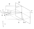
FIG. 1 is a schematic configuration diagram of a projector according to the present embodiment. FIG. 2 is a perspective view schematically showing a change in the cross-sectional shape of the light beam from the light source unit. FIG. 3 is a diagram for explaining the operation of the condensing angle changing lens and the diverging angle lens used in the projector.
In the following drawings, in order to make each component easy to see, the scale of the size may be varied depending on the component.
本実施形態のプロジェクター1は、図1に示すように、照明装置2と、照明光を変調して画像情報を内包した投写光を生成する光変調素子3(画像形成素子)と、光変調素子3から射出された投写光をスクリーン4などの被投写面に投写する投写光学系5と、を備えている。
以下の説明では、照明装置2から射出される照明光の略中心軸を「照明光軸L」と称し、第1光源部6、第2光源部7の各々のリフレクターの光軸をそれぞれ「ランプ光軸L1」、「ランプ光軸L2」と呼称する。「ランプ光軸」は、特許請求の範囲中の「射出光軸」に対応する。
As shown in FIG. 1, the
In the following description, the substantially central axis of the illumination light emitted from the
本実施形態の照明装置2は、2つの光源部6,7と、集光角変更レンズ8(集光角変更素子)と、反射プリズム9(光軸変換素子)と、2つの発散角変更レンズ10,11(発散角変更素子)と、インテグレータ部12と、を主に備えている。集光角変更レンズ8は、各光源部6,7から射出された光束の集光角を制御するためのものである。反射プリズム9は、2つの反射面9a,9bを備えた三角柱状のプリズムであり、2つの光源部6,7から射出された各光束を異なる反射面9a,9bで略一方向に反射させ、反射された光束を合成光束として略一方向に射出させるものである。2つの発散角変更レンズ10,11は、反射プリズム9からの発散光束の発散角を制御するためのものである。以下、2つの光源部6,7の各々を第1光源部、第2光源部と呼称する。本例では、図1において反射プリズム9に対して+x方向に位置する光源部を第1光源部6、−x方向に位置する光源部を第2光源部7と呼称する。また、2つの発散角変更レンズ10,11の各々を反射プリズムに近い側から第1発散角変更レンズ、第2発散角変更レンズと呼称する。
The illuminating
各光源部6,7からランプ光軸L1,L2に沿って射出された光束は、集光角変更レンズ8により所望の集光角を有する集束光束となって反射プリズム9に入射し、その反射面9a,9bで進行方向を略90度変えられるとともに発散光束となり、照明光軸Lに沿って配置された第1発散角変更レンズ10、第2発散角変更レンズ11に順次入射する。各光源部6,7から2つの発散角変更レンズ10,11に入射した発散光束は、その発散性が弱められ、照明光軸Lに対して略平行な合成光束となってインテグレータ部12に入射する。インテグレータ部12では、照明対象における照度分布が略均一な照明光束に変換され、照明対象である光変調素子3を照明する。光変調素子3としては、画素構造を備えた液晶表示素子や複数の可動ミラーをアレイ状に備えた微小ミラーアレイ素子が用いられる。光変調素子3に入射した照明光束は、外部からの情報に応じて変調され、画像情報を内包した投写光束となって射出される。射出された投写光束は、投写レンズ等の投写光学系5によってスクリーン4などの被投写面上に導かれ、画像情報を表示する。
The light beams emitted from the
2つの光源部6,7は、いずれも同一の構成であり、発光ランプ14(発光体)と、リフレクター15と、UV・IRカットフィルター16と、を備えている。発光ランプ14としては、高圧水銀ランプ、メタルハライドランプ、キセノンランプ、発光ダイオード(LED)等を使用できる。リフレクター15としては、放物面形状の反射面を備え、略平行な光束を射出する放物面リフレクターの使用が好適である。発光ランプ14は、その発光点がリフレクター15の焦点に略位置するように配置される。発光ランプ14から放射された光は、リフレクター15で反射され、ランプ光軸L1,L2に対して略平行な光束となって射出され、UV・IRカットフィルター16で不要な紫外光と赤外光とが除去される。UV・IRカットフィルター16を透過した略平行な光束は、トーリック面を有する集光角変更レンズ8に入射し、ランプ光軸L1,L2と互いに直交する方向で異なる集光角を有する集束光束に変換される。
The two
図2に示すように、第1光源部6から射出された光束は、ランプ光軸L1と互いに直交するz方向(反射プリズム9で反射された後はx方向)とy方向とにおいて、集光角変更レンズ8(不図示)によって異なる集光角を伴って集光されつつ反射プリズム9に入射し、反射プリズム9で反射された後は発散光束となって発散角変更レンズ10(不図示)に向かう。ここで、反射プリズム9は集束光束のz方向における光束径が最小となる位置に配置されている。これにより、集束光束のz方向における光束径は反射プリズム9の反射面9aの極近傍で最小となる。なお、反射面9a(あるいは反射面9aの法線)はランプ光軸L1に対して略45度傾斜させて配置されているため、図中に破線で示す射影像のように、反射面9aでの光束径は傾斜方向に伸張される。したがって、この射影像が反射プリズム9の頂点9t(2つの反射面9a,9bに接する稜線)に接しつつ、その像がほとんど欠けることなく形成されるように、反射プリズム9は配置される。一方、集束光束のy方向における光束径は反射プリズム9の手前(第1光源部6側)の段階で最小となり、最小径よりも大きくなった状態で反射面9aに入射する。
As shown in FIG. 2, the light beam emitted from the first
このような光束径の変化の様子と集光角変更レンズ8および発散角変更レンズ10,11の作用との関係を、図3を用いて説明する。
図3(A)〜(F)は、説明を判りやすくするために、実際には図2のように反射プリズム9の反射面9aで略90度折れ曲がっている第1光源部6から第2発散角変更レンズ11に至るまでの光路を、ランプ光軸L1がz軸を向くように直線的に描いた図である。
図3(A)は、2つのランプ光軸L1,L2を含む平面(xz平面)における光束径の変化の様子を示す図であり、図3(B)は、2つのランプ光軸L1,L2を含む平面(xz平面)に垂直な平面(yz平面)における光束径の変化の様子を示す図である。図3(C)、(D)、(E)、(F)は、それぞれ図3(A)、(B)中のP1,fy,fx,P2の各位置における集束光のxy平面での断面形状を模式的に示した図である。ただし、図3(A)〜(F)では第1光源部から反射プリズムの反射面に至るまでのランプ光軸をz軸に一致させて描いているため、図3(C)、(D)に示す断面形状は図1に示す実際の装置ではyz平面での断面形状である。
The relationship between the change of the light beam diameter and the operation of the condensing
3A to 3F, in order to make the explanation easy to understand, the second divergence from the first
FIG. 3A is a diagram illustrating a change in the light beam diameter on a plane (xz plane) including two lamp optical axes L1 and L2, and FIG. 3B is a diagram illustrating two lamp optical axes L1 and L2. It is a figure which shows the mode of a change of the light beam diameter in the plane (yz plane) perpendicular | vertical to the plane (xz plane) containing x. 3 (C), (D), (E), and (F) are cross sections on the xy plane of the focused light at positions P1, fy, fx, and P2 in FIGS. 3 (A) and 3 (B), respectively. It is the figure which showed the shape typically. However, in FIGS. 3A to 3F, since the lamp optical axis from the first light source unit to the reflecting surface of the reflecting prism is drawn so as to coincide with the z-axis, FIGS. The cross-sectional shape shown in FIG. 1 is a cross-sectional shape in the yz plane in the actual apparatus shown in FIG.
発光ランプ14の発光部は点状ではなく、有限の大きさを有する発光体である。よって、発光ランプ14からの光を集束した場合も、点状には集束せず、有限の光束径を持つ集束光となる。よって、位置fyはy方向における断面寸法が最小となる位置を示し、位置fxはx方向における断面寸法が最小となる位置を示し、位置P1は集光角変更レンズ8の射出側近傍における任意の位置を示し、位置P2は第1発散角変更レンズ10の入射側近傍における任意の位置を示している。また、以下では第1光源部6から第2発散角変更レンズ11に至る光を例に挙げて説明するが、第2光源部7から第2発散角変更レンズ11に至る光については、第2光源部7から反射プリズム9までの光の進行方向が逆向きである点を除いて、光束径や集束角の変化の状態は第1光源部からの光と同様である。
The light-emitting portion of the light-emitting
本実施形態の集光角変更レンズ8は、x方向に比べてy方向の曲率半径が小さいトーリック面を有している。すなわち、集光角変更レンズ8のx方向の焦点距離をLx1、y方向の焦点距離をLy1とすると、これらの大小関係はLx1>Ly1となっている。これにより、集光角変更レンズ8に入射した略平行な光束は、x方向に比べてy方向により大きな集光角を有する集束光束に変換されて射出される。そのため、集束光束のxy平面(位置P1、fyについては実質的にはyz平面)での断面寸法に着目すると、図3(C)、(D)に示すように、位置fyにおける光束径はy方向では最小径dy1であるが、x方向では位置P1に比べて小さくなっているものの、未だ最小径には至らない光束径dx1である。逆に、図3(E)に示すように、位置fxにおける光束径はx方向では最小径dx2であるが、y方向では最小径よりも大きくなった光束径dy2である。すなわち、x方向についてはdx1>dx2であり、y方向についてはdy1<dy2である。
The condensing
図1に示すように、反射プリズム9では、2つの光源部6,7から射出されて−x方向あるいはx方向に進行する光をz方向に反射させるため、2つの反射面9a,9bの法線がxz平面上に位置し、かつ、2つの反射面9a,9bがランプ光軸L1,L2および照明光軸Lに対して略45度の角度をなすように配置される。ここで、2つの光源部6,7からの光束を効率良く合成するとともに、後段の光学素子等での光利用効率を高めるためには、2つの発散光束からなる合成光束の光束径と角度分布の広がりを小さくすることが重要となる。したがって、2つの反射面9a,9bに入射する光束の径を、2つの光源部6,7からの光束を合成する方向(ランプ光軸L1,L2の配列方向)において小さくするとともに、反射プリズム9の頂点9t(2つの反射面に接する稜線)に近い位置で光束を反射させ、照明光軸Lとランプ光軸L1,L2とを近接させることが重要となる。ただし、2つの光源部6,7からの光束の射影像が欠けることなく反射面9a,9b上に略形成されるような位置で光束を反射させることが望ましい。なお、以下では2つの光源部6,7からの光束を合成する場合の効率を「合成効率」と呼ぶ場合がある。
As shown in FIG. 1, in the reflecting
そのため、図3(A)に示すように、xz平面において光束径が最小となる位置fxで、反射プリズム9の頂点9tがランプ光軸L1から光束径dx2の半分の距離Dだけ離れるように反射面9a(およびランプ光軸L1)は配置される。この配置関係によって、反射面9aに入射した光束の射影像は頂点9tに接するように形成される。これにより、反射プリズム9に入射したほとんど全ての光束は反射面9aで反射されるとともに、反射後は照明光軸Lに極近い位置を通って第1発散角変更レンズ10に入射する。一方、反射面9aに入射する光束のy方向における光束径の程度(大小)は、照明光軸Lと反射面9a(およびランプ光軸L1)との位置関係、すなわち上述の合成効率に影響を及ぼさないため、y方向の光束径は最小化する必要がない。したがって、反射面9aに入射するときの光束の断面は、xz平面では最小径であるものの、yz平面では最小径よりも大きな光束径となっている。このとき、反射面9aに入射するときの光束の反射面9aに沿った断面を考えると、xz平面上の断面寸法が最小であり、xz平面に直交するy軸方向の断面寸法が最小寸法よりも大きくなっている。
Therefore, as shown in FIG. 3A, reflection is performed such that the
反射面9aで反射された光束は、発散光束となって照明光軸Lに沿って順次配置された第1発散角変更レンズ10、第2発散角変更レンズ11に入射する。ここで、第1発散角変更レンズ10は、y方向にのみ曲率を有するシリンドリカルレンズである。一方、第2発散角変更レンズ11は、x方向にのみ曲率を有するシリンドリカルレンズである。換言すると、第1発散角変更レンズ10は、y方向の焦点距離がLy2、x方向の曲率半径が無限大であり、第2発散角変更レンズ11は、x方向の焦点距離がLx2、y方向の曲率半径が無限大である。第1発散角変更レンズ10は、図3(B)に示すように、y方向の光束径が最小となる位置fyから焦点距離Ly2だけ離れた位置に配置され、第2発散角変更レンズ11は、図3(A)に示すように、x方向の光束径が最小となる位置fxから焦点距離Lx2だけ離れた位置に配置される。
The light beam reflected by the reflecting
したがって、これらの発散角変更レンズ10,11に入射した発散光束は、第1発散角変更レンズ10によりy方向の発散性を弱められ、次いで、第2発散角変更レンズ11によりx方向の発散性を弱められて照明光軸Lと略平行な光束となり、射出される。厳密には、2つの発散角変更レンズ10,11はそれらの中心を照明光軸Lが通過するように配置されているのに対して、2つのランプ光軸L1,L2は反射面9a,9bで折れ曲がった後、照明光軸Lと僅かな距離Dを隔てて平行に配置されており、各発散光束は対応するランプ光軸L1,L2に沿って2つの発散角変更レンズ10,11に入射する。したがって、第2発散角変更レンズ11から射出される合成光束は、距離Dに起因する角度分布の広がりを有する光束となるが、角度分布の広がりは僅かであるため、概ね平行な光束と見なすことができる。
Accordingly, the divergent light beams incident on these divergent
第2発散角変更レンズ11から射出された光束は、図1に示すように、2つのレンズアレイ18,19、重畳レンズ20、平行化レンズ21等を含むインテグレータ部12に入射し、照明対象における照度分布が略均一な照明光束に変換され、照明対象である光変調素子3を照明する。
As shown in FIG. 1, the light beam emitted from the second divergence
本実施形態の照明装置2によれば、反射プリズム9において2つの光源部6,7からの光束を反射させて合成光束を生成する方向(2つの光束の合成方向、x方向もしくはz方向)における光束径が最小となる位置fxで、反射プリズム9の頂点9tにごく近い位置に各光源部6,7のランプ光軸L1,L2が位置するように反射プリズム9の反射面9a,9bが配置されているため、光束径と角度分布の広がりの小さい合成光束を得ることができる。また、2つの光束の合成方向と直交する方向(図2中の矢印Y方向)については光束径を最小化する必要がなく、また、反射面9a,9bの寸法にも制約が少ないため、y方向に広がった光束を入射させることができる。すなわち、反射面9a,9bに入射する光束の断面寸法がランプ光軸L1,L2と互いに直交する2方向で略同一である従来の光学系の場合と比べて、集光角変更レンズ8を用いて、反射面9a,9bに入射する光束の断面寸法をランプ光軸L1,L2と互いに直交する2方向で異なる光束を生成することによって、合成効率を低下させることなく反射面9a,9bに入射する光束の断面積を大きくでき、反射面9a,9bに入射する光の単位面積あたりの強度を低減できる。その結果、局所的な熱や熱歪みの発生が抑制され、光や熱による反射面の劣化を防止できる。
According to the
また、反射面9a,9bで反射された発散光束を、2つの発散角変更レンズ10,11によって照明光軸Lに対して概ね平行な光束とすることができる。したがって、2つの光源部6,7から射出された光束の進行方向を反射プリズム9によって変え、2つの光束から合成光束を生成する過程において、光束径が最小となる位置を照明光軸Lと互いに直交する2方向で異ならせる工程を採用しても、発散角変更レンズ10,11以降の光学系における照明効率(光利用効率)の低下を招くことがほとんどない。以上により、高い光出力を長期にわたって安定的に得られる照明装置を実現できる。さらに、このような照明装置2を備えたことにより、投写画像の表示品位が高く、耐久性に優れたプロジェクター1を実現できる。
Further, the divergent light beam reflected by the reflecting
なお、集光角変更レンズ8、第1発散角変更レンズ10、第2発散角変更レンズ11としては、上述したような単レンズで構成する以外にも、複数のレンズを用いた複合レンズ系、面の曲率が非球面状に変化する非球面レンズ、レンズ面に回折格子を形成したハイブリッドレンズ系、回折素子やホログラム素子を用いた光学系等であっても良い。これらの構成を採用した場合、光束の集光性を一層高められるため、より小径の集束光を生成でき、好適である。
また、2つの反射面9a,9bのランプ光軸L1,L2および照明光軸Lに対する設置角度は、本実施形態に限定されない。すなわち、反射面9a,9bでの反射角を45度以外に設定した光学配置としても良い。このような構成例については、第5実施形態で説明する。
Note that the condensing
Further, the installation angles of the two reflecting
[第2実施形態]
以下、本発明の第2実施形態について、図4、図5を用いて説明する。
本実施形態の照明装置の基本構成は第1実施形態と同様であり、集光角変更レンズの集光特性が第1実施形態と異なるのみである。
図4、図5は、上記第1実施形態の照明装置の説明に用いた図2、図3に対応する図である。図4、図5において、図2、図3と共通の構成要素については同一の符号を付し、詳細な説明は省略する。
[Second Embodiment]
Hereinafter, a second embodiment of the present invention will be described with reference to FIGS.
The basic configuration of the illumination device of the present embodiment is the same as that of the first embodiment, and only the condensing characteristic of the condensing angle changing lens is different from that of the first embodiment.
FIGS. 4 and 5 are views corresponding to FIGS. 2 and 3 used for explaining the illumination device of the first embodiment. 4 and 5, the same reference numerals are given to the same components as those in FIGS. 2 and 3, and detailed description thereof is omitted.
図2、図3に示した上記第1実施形態の照明装置は、x方向における光束の集束位置fxに対してy方向における光束の集束位置fyが光源部寄りに位置する、すなわち、ランプ光軸L1と互いに直交するx方向とy方向とにおいて、x方向よりもy方向の方が光束の集光角が大きくなる構成であった。これに対して、本実施形態の照明装置は、図4、図5に示すように、集光角変更レンズ28により、x方向における光束の集束位置fxに対してy方向における光束の集束位置fyが照明対象寄りに位置する、すなわち、x方向よりもy方向の集光角が小さくなる構成である。
2 and 3, the illumination apparatus of the first embodiment has a light beam focusing position fy in the y direction that is closer to the light source portion than a light beam focusing position fx in the x direction, that is, a lamp optical axis. In the x direction and the y direction perpendicular to L1, the light collection angle is larger in the y direction than in the x direction. On the other hand, as shown in FIGS. 4 and 5, the illuminating device according to the present embodiment has a light beam converging position fy in the y direction with respect to a light converging position fx in the x direction by the condensing
本実施形態の照明装置においても、光束径と角度分布の広がりが小さい合成光束を効率良く得られるとともに、耐久性が高く、長期にわたって安定して高い光出力を有する照明装置を実現できる、という第1実施形態の照明装置と同様の効果が得られる。さらに、本実施形態の構成によれば、上記実施形態の場合と比べて、集光角変更レンズ28から第2発散角変更レンズ11までの距離が長くなるが、集光角が相対的に小さくなるため、2つの発散角変更レンズ10,11から射出される光束の平行性を高められる。したがって、第2発散角変更レンズ11の後段に入射角依存性を有する光学系、例えばインテグレータ、偏光変換光学系、ダイクロイック素子、液晶ライトバルブなどが配置される場合には、これらの光学系における光利用効率を高められるという利点がある。
Also in the illumination device of the present embodiment, it is possible to efficiently obtain a synthesized light beam with a small beam diameter and angular distribution, and to realize a lighting device having high durability and having a high light output stably over a long period of time. The same effect as that of the illumination device according to the embodiment can be obtained. Furthermore, according to the configuration of the present embodiment, the distance from the condensing
[第3実施形態]
以下、本発明の第3実施形態について、図6〜図8を用いて説明する。
本実施形態の照明装置の基本構成は第1、第2実施形態と同様であり、リフレクターの集光特性が第1、第2実施形態と異なるのみである。
図6〜図8は、上記第1実施形態の照明装置の説明に用いた図3、上記第2実施形態の照明装置の説明に用いた図5に対応する図である。図6〜図8において、図3、図5と共通の構成要素については同一の符号を付し、詳細な説明は省略する。
[Third Embodiment]
Hereinafter, a third embodiment of the present invention will be described with reference to FIGS.
The basic configuration of the illumination device of the present embodiment is the same as that of the first and second embodiments, and the light collection characteristics of the reflector are only different from those of the first and second embodiments.
6 to 8 are views corresponding to FIG. 3 used for describing the lighting device of the first embodiment and FIG. 5 used for describing the lighting device of the second embodiment. 6 to 8, the same components as those in FIGS. 3 and 5 are denoted by the same reference numerals, and detailed description thereof is omitted.
第1、第2実施形態の照明装置は、光源部に放物面リフレクターを備えていたのに対し、本実施形態の照明装置は、光源部26に楕円リフレクター25を備えている。楕円リフレクター25の第1焦点に発光ランプ14の発光点が位置するように配置され、発光点から放射された光は楕円リフレクター25で反射されて第2焦点に集束する。図6は、ランプ光軸L1と互いに直交するx方向とy方向とにおいて、x方向よりもy方向の方が光束の集光角が大きい構成を示し、図7は、x方向よりもy方向の方が光束の集光角が小さい構成を示している。これらの図に示すように、楕円リフレクター25から射出される光束は、ランプ光軸L1を対称軸とする集束光束であり、ランプ光軸L1と互いに直交する2方向において等しい集光角を有している。したがって、本実施形態の集光角変更レンズ29,30としては、2方向のうちのいずれか一方の集光角を変える機能を持っていれば良く、凸面もしくは凹面を有するシリンドリカルレンズを用いることができる。
The illumination devices of the first and second embodiments are provided with a parabolic reflector in the light source unit, whereas the illumination device of the present embodiment is provided with an
凸面を有するシリンドリカルレンズを用いれば、曲率(屈折力)を有する方向において光束の集光角を大きくでき、一方、凹面を有するシリンドリカルレンズを用いれば、曲率(屈折力)を有する方向において光束の集光角を小さくできる。勿論、シリンドリカルレンズは単レンズで構成する以外にも、複数のレンズを用いた複合レンズ系、面の曲率が非球面状に変化する非球面レンズ、レンズ面に回折格子を形成したハイブリッドレンズ系、回折素子やホログラム素子を用いた光学系等であっても良い。これらの構成を採用した場合、光束の集光性を一層高められるため、より小径の集束光を生成でき、好適である。 If a cylindrical lens having a convex surface is used, the converging angle of the light beam can be increased in a direction having a curvature (refractive power). On the other hand, if a cylindrical lens having a concave surface is used, the light beam can be collected in a direction having a curvature (refractive power). The light angle can be reduced. Of course, the cylindrical lens is not only composed of a single lens, but also a compound lens system using a plurality of lenses, an aspherical lens in which the curvature of the surface changes to an aspherical shape, a hybrid lens system in which a diffraction grating is formed on the lens surface, An optical system using a diffraction element or a hologram element may be used. When these structures are adopted, the light condensing property can be further improved, so that it is possible to generate focused light having a smaller diameter, which is preferable.
本実施形態の照明装置においても、光束径と角度分布の広がりが小さい合成光を効率良く得られるとともに、耐久性が高く、長期にわたって安定して高い光出力を有する照明装置を実現できる、という第1実施形態の照明装置と同様の効果が得られる。さらに、本実施形態の構成によれば、シリンドリカル面を有する集光角変更レンズ29,30はトーリック面を有する集光角変更レンズに比べて製造が容易であり、光学系の低コスト化を実現しやすい。また、楕円リフレクター25から光束が射出された段階で既に集束光束となっているため、光源部6から集束位置fx,fyまでの距離を短くでき、光学系を小型化しやすい。加えて、楕円リフレクター25と放物面リフレクターとを比べると、ランプ光軸L1に直交する方向における口径が同じ場合には、楕円リフレクターのほうが発光ランプ14からの光をより多く取り込むことができ、光利用効率を高めやすいことが知られている。本実施形態の照明装置では、光源部26が楕円リフレクター25を備えているため、高い光出力を実現することができる。
In the illumination device of the present embodiment as well, it is possible to efficiently obtain synthesized light having a small beam diameter and a wide angular distribution, and to realize an illumination device that has high durability and stably has a high light output over a long period of time. The same effect as that of the illumination device according to the embodiment can be obtained. Furthermore, according to the configuration of the present embodiment, the converging
なお、図6、図7では、集光角変更レンズ29,30として、凸面を有するシリンドリカルレンズを用いた場合を説明したが、2方向のうちのいずれか一方の集光角を変える機能を持っていさえすれば良いため、後述する様に、凹面を有するシリンドリカルレンズを用いた構成としても良い。
In FIGS. 6 and 7, the case where cylindrical lenses having convex surfaces are used as the condensing
図8は、本実施形態の変形例を示す説明図であり、図6に対応する図である。図に示す集光角変更レンズ31は、凹面を有するシリンドリカルレンズであり、y方向にのみ曲率を有している。集光角変更レンズ31は、楕円リフレクター25の曲率に基づいて、光源部26から射出される集束光束を、y方向において略平行光に変換できる曲率を有するものを選択する。
FIG. 8 is an explanatory diagram showing a modification of the present embodiment, and corresponds to FIG. The condensing
そのため、図8(A)に示すように、光源部26から射出される集束光束は、集光角変更レンズ31を透過することにより、x方向においては集光角が変更されることなく、集束光束として反射プリズム9に入射する。一方、図8(B)に示すように、y方向においては、光源部26から射出される集束光束は、集光角が変更され略平行光として反射プリズム9に入射する。反射プリズム9で反射した光は、x方向にのみ曲率を有するシリンドリカルレンズである発散角変更レンズ11を透過することで、略平行光に変換されて射出される。
Therefore, as shown in FIG. 8A, the converged light beam emitted from the
このような構成であっても、上述のように集光角変更レンズ29,30として凸面を有するシリンドリカルレンズを備えた構成と同様に、光束径と角度分布の広がりが小さい合成光を効率良く得られるとともに、耐久性が高く、長期にわたって安定して高い光出力を有する照明装置を実現できる、という第1実施形態の照明装置と同様の効果が得られる。
Even in such a configuration, as in the configuration including the cylindrical lenses having convex surfaces as the converging
[第4実施形態]
以下、本発明の第4実施形態について、図9,図10を用いて説明する。
本実施形態の照明装置の基本構成は第3実施形態と同様であり、反射プリズム9への入射前と、反射プリズム9からの射出後(反射後)に、光源部から射出された光が更にレンズを透過することが第3実施形態と異なるのみである。
図9、図10は、上記第3実施形態の照明装置の説明に用いた図8に対応する図であり、図9と図10では、光源部のリフレクターの集光特性と、光源部から射出される光が入射する集光角変更レンズの構成と、が異なっている。図9、図10において、図8と共通の構成要素については同一の符号を付し、詳細な説明は省略する。
[Fourth Embodiment]
Hereinafter, a fourth embodiment of the present invention will be described with reference to FIGS.
The basic configuration of the illuminating device of this embodiment is the same as that of the third embodiment. Light emitted from the light source unit is further emitted before entering the reflecting
FIGS. 9 and 10 are views corresponding to FIG. 8 used for explaining the illumination device of the third embodiment. In FIGS. 9 and 10, the light collection characteristics of the reflector of the light source unit and the light emitted from the light source unit are shown. The configuration of the condensing angle changing lens on which the incident light is incident is different. 9 and 10, the same components as those in FIG. 8 are denoted by the same reference numerals, and detailed description thereof is omitted.
図9に示す本実施形態の照明装置は、放物面リフレクター15を有する光源部6と、x方向にのみ曲率を有するシリンドリカルレンズである集光角変更レンズ30と、反射プリズム9と、の間の光路上に、平行化レンズ34を有し、反射プリズム9と発散角変更レンズ11との間の光路上に発散光変換レンズ(発散光変換素子)35を有している。平行化レンズ34、発散光変換レンズ35は、いずれも凹面を有するシリンドリカルレンズであり、後段に設けられている発散角変更レンズ11と同じ方向(x方向)にのみ曲率を有している。平行化レンズ34は、集光角変更レンズ30の焦点位置(集束位置fx)よりも光源部6側に配置されており、発散光変換レンズ35は、集光角変更レンズ30の焦点位置(集束位置fx)よりも光源部6とは反対側(発散角変更レンズ11側)に配置されている。
The illuminating device of the present embodiment shown in FIG. 9 includes a
本実施形態の照明装置では、このような平行化レンズ34、発散光変換レンズ35を備えることにより、放物面リフレクター15を備えた光源部6から射出された略平行光は、まず集光角変更レンズ30によってx方向のみが集光する集束光束に変換される。集束光束は、集束位置fxに向かって集束するが、集束位置fxに達する前に平行化レンズ34に入射して略平行光に変換されて、反射プリズム9に入射する。反射プリズム9で反射した略平行光は、発散光変換レンズ35によってx方向のみが発散する光束に変換され、次いで入射する発散角変更レンズ11を透過することにより、略平行光に変換されて射出される。なお、反射プリズム9は、第1実施形態と同様に、反射面9aにおける集束光束の射影像が、反射プリズム9の頂点9tに接しつつ、その像がほとんど欠けることなく形成されるように配置されている。
In the illuminating device of this embodiment, by providing such a
図10に示す本実施形態の他の照明装置は、楕円リフレクター25を有する光源部26を有している。光源部26から射出される集束光束は、凹面を有するシリンドリカルレンズである集光角変更レンズ31に入射する。集光角変更レンズ31は、y方向にのみ曲率を有しており、自身に入射する集束光束について、y方向を略平行光に変換することで、x方向のみが集光する集束光束に変換する。
Another illumination device of this embodiment shown in FIG. 10 includes a
その後は、上述の図9の構成と同様に、平行化レンズ34を介することにより、x方向が集束した略平行光が反射プリズム9に入射し、発散光変換レンズ35および発散角変更レンズ11を介することにより、反射プリズム9から射出された略平行光よりもx方向が拡大された略平行光に変換されて射出される。
Thereafter, similar to the configuration of FIG. 9 described above, the substantially parallel light focused in the x direction is incident on the reflecting
本実施形態の照明装置においても、反射プリズム9に入射する光がx方向に集束しているため、光束径と角度分布の広がりが小さい合成光を効率良く得られるとともに、耐久性が高く、長期にわたって安定して高い光出力を有する照明装置を実現できる、という第1実施形態の照明装置と同様の効果が得られる。また、本実施形態の構成によれば、反射プリズム9に入射する光が略平行光であるため、反射面9aに入射する光の入射角度範囲を狭めることができ、反射面9aでの反射率を向上させることができる。さらに、集束位置fxに基づいて定まる位置に限ることなく、反射プリズム9を配置可能であるため、反射プリズム9の配置自由度が高まり、設計自由度が高い照明装置とすることができる。
Also in the illumination device of the present embodiment, since the light incident on the reflecting
なお、本実施形態では、平行化レンズ34、発散光変換レンズ35をシリンドリカルレンズであることとしたが、これに限らない。例えば、集光角変更レンズがトーリック面を有するトーリックレンズである場合には、平行化レンズ34、発散光変換レンズ35に対応するレンズとして、該集光角変更レンズと同じ方向に異なる曲率を有する平行化レンズおよび発散角変更レンズを用いることとしても良い。
In the present embodiment, the collimating
[第5実施形態]
以下、本発明の第5実施形態について、図11、図12を用いて説明する。
本実施形態の照明装置の基本構成は第1実施形態と同様であり、反射プリズムに対する光源部の配置が第1実施形態と異なっている。
図11は、本実施形態の照明装置を備えたプロジェクター41の概略構成図であり、図12は、本実施形態の他の例の照明装置を備えたプロジェクター43の概略構成図である。
図11、図12において、図1と共通の構成要素については同一の符号を付し、詳細な説明は省略する。
[Fifth Embodiment]
Hereinafter, a fifth embodiment of the present invention will be described with reference to FIGS. 11 and 12.
The basic configuration of the illumination device of this embodiment is the same as that of the first embodiment, and the arrangement of the light source unit with respect to the reflecting prism is different from that of the first embodiment.
FIG. 11 is a schematic configuration diagram of a
In FIG. 11 and FIG. 12, the same components as those in FIG. 1 are denoted by the same reference numerals, and detailed description thereof is omitted.
第1実施形態の照明装置2は、反射プリズム9の反射面9a,9bでランプ光軸L1,L2を略90度折り曲げた後、照明光軸Lに対して2つのランプ光軸L1,L2を略平行に配置した構成とした。これに対して、図11に示す本実施形態の照明装置42は、第1光源部6のランプ光軸L1と照明光軸Lとのなす角度が+θ、第2光源部7のランプ光軸L2と照明光軸Lとのなす角度が−θとなるように第1、第2光源部6,7が配置されている。図11の構成では、第1実施形態と同様、照明光軸Lに対して45度の角度をなす反射面9a,9bを有する反射プリズム9を使用しており、照明光軸Lと直交する軸L’に対して第1光源部6のランプ光軸L1が−θの角度をなし、第2光源部7のランプ光軸L2が+θの角度をなすように第1、第2光源部6,7が配置されている。
In the illuminating
本実施形態の照明装置42においても、光束径と角度分布の広がりが小さい合成光束を効率良く得られるとともに、耐久性が高く、長期にわたって安定して高い光出力を有する照明装置を実現できる、という第1実施形態の照明装置と同様の効果が得られる。さらに、反射プリズム9の反射面9a,9bが照明光軸Lとなす角度を変え、例えば45度以外の任意の角度に設定すれば、2つの光源部6,7をxz平面上の任意の位置に配置でき、照明装置の設計やデザインにおける自由度を向上できる。
Also in the
例えば、図12に示す本実施形態の照明装置44では、照明光軸Lに対して45度よりも大きい角度をなす反射面49a,49bを有する反射プリズム49を使用している。第1光源部6および第2光源部7は、反射面49a,49bへの入射角φ(反射面49a,49bの法線とランプ光軸L1,L2とが成す角度)が45度未満となるように、且つ、反射面49a,49bで反射した後は、ランプ光軸L1およびランプ光軸L2は照明光軸Lと略平行となるように配置されている。
For example, the illuminating
このように、反射プリズム49の反射面49a,49bが照明光軸Lと大きな角度をなすように、換言すると三角柱状の反射プリズム9の頂角が鈍角となるようにすれば、反射プリズム49を通って照明光軸Lと直交する軸L’よりも照明対象側に2つの光源部6,7を配置することができる。このような構成にすれば、各光源部6,7からの集束光束が反射プリズム49の反射面49a,49bに入射する際の入射角を小さくでき、反射面49a,49bに入射する際の光束径の拡大(射影像の拡幅)を抑えることができる。具体的には、各光源部6,7のランプ光軸L1,L2が反射面49a,49bの法線と成す角度を入射角φとすると、入射面内においては、反射面9a,9bに形成される光束の射影像の寸法は、光束断面の寸法の1/cosφ倍となるため、入射角φを小さくするほど光束断面の寸法を小さくすることができる。
In this way, if the reflecting
図12(B)は、反射プリズム9を反射光の射出方向(z方向)から見た図であり、反射面に入射する直前での光束の断面形状(破線で示す符号BS1)、および反射面49a,49bにおける光束の断面形状(実線で示す符号BS2)を示す模式図である。反射面49a,49bに対して斜めから光束を照射すると、傾斜方向へ光束径が伸張し光束径が拡大するが、照明装置44のように入射角φが小さい場合、このような光束径の伸張が軽減されるため、射影像の光束径を小さくすることができる。
FIG. 12B is a view of the reflecting
このような照明装置44では、第1実施形態の照明装置と同様の効果に加え、反射プリズム49の頂点49tにより近い位置で、各光源部6,7から射出される光束を反射させることができるため、合成光束の光束径と角度分布の広がりをより小さくできる。また、照明装置の奥行き寸法を小さくでき、装置を小型化できる。
In such an illuminating
なお、上述の全ての実施形態では、反射プリズム9以降(投写光学系5側)において2つのランプ光軸L1,L2はいずれも照明光軸Lと平行となるように設定されていたが、本実施形態の照明装置42の様に、発散角変更レンズやインテグレータ光学系の入射端において、全てのランプ光軸が照明光軸Lと交わるように、ランプ光軸を設定しても良い。このような構成においては、発散角変更レンズやインテグレータ光学系に入射する合成光束の光束径を、上述の実施形態の場合と比べて一層小さくできるため、光学系の小型化やインテグレータ光学系以降の光学系での光利用効率を向上できる。
In all the embodiments described above, the two lamp optical axes L1 and L2 are set so as to be parallel to the illumination optical axis L after the reflecting prism 9 (on the projection
[第6実施形態]
以下、本発明の第6実施形態について、図13、図14を用いて説明する。
本実施形態の照明装置の基本構成は第1実施形態と同様であり、照明装置に偏光変換光学系を加えた点のみが第1実施形態と異なっている。
図13は、本実施形態の照明装置を備えたプロジェクター51の概略構成図である。図14は、本照明装置の偏光変換光学系を構成するPBSアレイと1/2波長板アレイを示す図である。
図13において、図1と共通の構成要素については同一の符号を付し、詳細な説明は省略する。
[Sixth Embodiment]
Hereinafter, a sixth embodiment of the present invention will be described with reference to FIGS.
The basic configuration of the illumination device of the present embodiment is the same as that of the first embodiment, and only the point that a polarization conversion optical system is added to the illumination device is different from the first embodiment.
FIG. 13 is a schematic configuration diagram of a
In FIG. 13, the same components as those in FIG. 1 are denoted by the same reference numerals, and detailed description thereof is omitted.
本実施形態の照明装置52は、図13に示すように、レンズアレイ19と重畳レンズ20との間に、偏光分離プリズムアレイ53(以下、PBSアレイと略記する)と1/2波長板アレイ54とからなる偏光変換光学系55を備えている。図14に示すように、PBSアレイ53における一対の偏光分離面と反射面とが配列された方向、すなわち偏光分離方向は、2つの光源部6,7が配置されたxz平面(各光源部6,7からの光束が合成される方向)と直交する方向(y方向)に設定されている。2つの発散角変更レンズ10,11、2つのレンズアレイ18,19を透過した合成光束は、偏光変換光学系55によって略一種類の偏光光束に変換され、照明対象である光変調素子3に入射する。特に、画像表示に際して偏光を扱う必要がある液晶表示素子を光変調素子3として用いる際には、偏光変換光学系55の採用は光利用効率を向上できる点で効果的である。
As shown in FIG. 13, the
本実施形態の照明装置52においても、光束径と角度分布の広がりが小さい合成光束を効率良く得られるとともに、耐久性が高く、長期にわたって安定して高い光出力を有する照明装置を実現できる、という第1実施形態の照明装置と同様の効果が得られる。
Also in the
ところで、PBSアレイ53を用いた偏光変換光学系55は、2つのレンズアレイ18,19で生成した部分光束の各々を偏光方向の違いによって更に空間的に分離し、偏光状態が異なる2種類の偏光部分光束を生成する。ここで、本実施形態の照明装置52では、2つの光源部6,7に対応して2つの部分光束がこれらの光束が合成される方向に並んで形成される。そのため、上述したように、PBSアレイ53における偏光分離方向を光束の合成方向と直交する方向に設定すれば、光源部の数に起因して生成される部分光束から更に偏光分離して生成された偏光部分光束を互いに近接させて配置できる。これにより、光束の1/2波長板アレイ54への入射効率を高められ、高い偏光変換効率を実現できる。
By the way, the polarization conversion optical system 55 using the
[第7実施形態]
以下、本発明の第7実施形態について、図15,図16を用いて説明する。
本実施形態の照明装置の基本構成は第1実施形態、第2実施形態と同様であり、照明装置が集光角変更レンズを備えていない点のみが第1実施形態、第2実施形態と異なっている。
図15(A)は、本実施形態の照明装置を備えたプロジェクター61の概略構成図である。図15(B)は、本照明装置に用いられるリフレクターの斜視図、図15(C)はリフレクターの断面形状を模式的に示す図である。また、図16は、上記第1実施形態の照明装置の説明に用いた図3に対応する図である。
図15,図16において、図1と共通の構成要素については同一の符号を付し、詳細な説明は省略する。
[Seventh Embodiment]
The seventh embodiment of the present invention will be described below with reference to FIGS.
The basic configuration of the illumination device of this embodiment is the same as that of the first embodiment and the second embodiment, and is different from the first embodiment and the second embodiment only in that the illumination device does not include a condensing angle changing lens. ing.
FIG. 15A is a schematic configuration diagram of a
15 and 16, the same reference numerals are given to the same components as those in FIG. 1, and detailed description thereof is omitted.
図15に示す本実施形態の照明装置62は、図15(A)に示すように、第1実施形態の照明装置と異なり、各光源部36,37から射出された光が入射する集光角変更レンズ8を備えておらず、UV・IRカットフィルター16から射出された光が反射プリズム9の反射面9a,9bに直接入射する構成となっている。図15(B)に示す本実施形態のリフレクター65は、x方向に光を射出する楕円リフレクターであるが、図15(C)に示すように、リフレクター65のxz平面における断面形状65xzとxy平面における断面形状65xyとが異なっており、xy平面よりもxz平面における曲率半径の方が大きい。このような構成のリフレクター65は、第1実施形態の集光角変更レンズ8と同様の機能を果たし、ランプ光軸L1,L2に互いに直交する2方向で異なる集光角を有する集束光束を生成する。
The
すなわち、2つの光源部36,37から射出した集束光束は、ランプ光軸L1,L2と互いに直交するz方向とy方向とにおいて、z方向における集光角がy方向における集光角よりも小さくなる。そのため、集束光束のy方向における光束径は反射プリズム9の反射面9a,9bよりも光源部36,37側で最小化した後、その最小径よりも大きくなった状態で反射面9a,9bに入射する。一方、z方向における光束径は最小径となった状態で反射面9a,9bに入射する。したがって、2つの光源部36,37からの光束を合成する場合の合成効率を低下させることなく、反射面9a,9bに入射する光束の単位面積あたりの強度を低減できる。
That is, the converged light beams emitted from the two
また、図16に示す本実施形態の他の例の照明装置では、光源部46が有するリフレクター66は、ランプ光軸L1を通るxz平面での断面形状は楕円形状となっており、ランプ光軸L1を通るyz平面での断面形状は放物線形状となっている。そのため、光源部46から射出される集束光束は、集束位置fxにおいてx方向のみが集束している。
In the illumination device of another example of this embodiment shown in FIG. 16, the
すなわち、集束光束のx方向における光束径は、最小化した状態で反射面9a,9bに入射する。一方、y方向における光束径は光源部46から射出された直後と変わらず略平行光のままで反射面9a,9bに入射する。したがって、2つの光源部からの光束を合成する場合の合成効率を低下させることなく、反射面9a,9bに入射する光束の単位面積あたりの強度を低減できる。
That is, the light beam diameter in the x direction of the focused light beam enters the reflecting
このような集束光束は、反射面9aで反射された後、発散角変更レンズ11に入射する。発散角変更レンズ11は、x方向にのみ曲率を有するシリンドリカルレンズである。そのため、発散角変更レンズ11に入射する集束光束は、発散角変更レンズ11を透過することにより略平行光に変換されて射出される。
Such a focused light beam is reflected by the reflecting
このような照明装置においても、光束径と角度分布の広がりが小さい合成光束を効率良く得られるとともに、耐久性が高く、長期にわたって安定して高い光出力を有する照明装置を実現できる、という第1実施形態の照明装置と同様の効果が得られる。さらに、本実施形態では集光角変更レンズ8が不要となり、部品点数の削減が図れる。
In such an illuminating device as well, it is possible to achieve a illuminating device that can efficiently obtain a synthesized light beam having a small beam diameter and angular distribution, and that has high durability and has a stable and high light output over a long period of time. The same effect as that of the illumination device of the embodiment can be obtained. Furthermore, in this embodiment, the condensing
[第8実施形態]
以下、本発明の第8実施形態について、図17〜図20を用いて説明する。
本実施形態の照明装置の基本構成は第1実施形態と同様であり、反射プリズムの代わりに、2つの反射ミラーで構成される反射部89を備えている点が第1実施形態と異なっている。
図17は、本実施形態の照明装置を備えたプロジェクター81の概略構成図である。図18は光源部からの光束の断面形状の変化の様子を模式的に示す斜視図である。図19は本プロジェクターに用いる集光角変更レンズや発散角レンズの作用を説明するための図である。図20は、本実施形態のプロジェクター81における作用を説明する説明図である。
図17〜図19において、既に説明済みの構成要素については既出の符号を付し、詳細な説明は省略する。
[Eighth Embodiment]
The eighth embodiment of the present invention will be described below with reference to FIGS.
The basic configuration of the illuminating device of this embodiment is the same as that of the first embodiment, and is different from the first embodiment in that it includes a reflecting
FIG. 17 is a schematic configuration diagram of a
17 to 19, the components already described are denoted by the same reference numerals, and detailed description thereof is omitted.
図17に示すように、本実施形態のプロジェクター81は、上述の実施形態と異なり、光変調素子を3枚備えた所謂3板式のプロジェクターとなっている。プロジェクター81は、概略すると以下のように動作する。
As shown in FIG. 17, the
まず、照明装置82から射出された光は、色分離光学系84により複数の色光に分離される。色分離光学系84により分離された複数の色光は、それぞれ対応する光変調素子3a〜3cに入射して変調される。光変調素子3a〜3cにより変調された複数の色光は、色合成素子88に入射して合成される。色合成素子88により合成された光は、投写光学系5によりスクリーン4に拡大投写され、フルカラーの投写画像が表示される。以下、プロジェクター81の各構成要素について説明する。
First, the light emitted from the
照明装置82が有する反射部89は、反射ミラー89Aと反射ミラー89Bとを有している。各反射ミラー89A,89Bは、それぞれ照明光軸Lと略45度の角度をなすとともに、xz平面の法線方向から視てX字状に重なるように、照明光軸Lをまたいで配置されている。各光源部6,7から射出された略平行光は、それぞれ反射ミラー89A,89Bで反射され、色分離光学系84に入射する。
The
色分離光学系84は、ダイクロイックミラー841、842、ミラー843〜845、平行化レンズ21a〜21c、リレーレンズ(リレー光学系)85、86を含んでいる。ダイクロイックミラー841、842は、例えばガラス表面に誘電体多層膜を積層したものである。ダイクロイックミラー841、842は、所定の波長帯域の色光を選択的に反射させ、それ以外の波長帯域の色光を透過させる特性を有している。ここでは、ダイクロイックミラー841が緑色光と青色光とを反射させ、ダイクロイックミラー842が緑色光を反射させる。
The color separation
照明装置82から射出された合成光束は、ダイクロイックミラー841に入射する。合成光束のうちの赤色光Laは、ダイクロイックミラー841を通ってミラー843に入射し、ミラー843で反射して平行化レンズ21aに入射する。赤色光Laは、平行化レンズ21aにより略平行化された後に、光変調素子3aに入射する。
The combined light beam emitted from the
また、合成光束のうちの緑色光Lbと青色光Lcとは、ダイクロイックミラー841で反射して、ダイクロイックミラー842に入射する。緑色光Lbは、ダイクロイックミラー842で反射して平行化レンズ21bに入射する。緑色光Lbは、平行化レンズ21bにより略平行化された後に、光変調素子3bに入射する。
Further, the green light Lb and the blue light Lc in the combined light flux are reflected by the
さらに、ダイクロイックミラー842を通った青色光Lcは、リレーレンズ85を通りミラー844で反射した後、リレーレンズ86を通りミラー845で反射して平行化レンズ21cに入射する。青色光Lcは、平行化レンズ21cにより略平行化された後に、光変調素子3cに入射する。
Further, the blue light Lc that has passed through the
光変調素子3a〜3cは、例えば透過型の液晶ライトバルブ等の光変調装置により構成される。光変調素子3a〜3cは、画像情報を含んだ画像信号を供給するPC等の信号源(図示略)と電気的に接続されている。光変調素子3a〜3cは、供給された画像信号に基づいて、入射光を画素ごとに変調して画像を形成する。光変調素子3a〜3cは、それぞれ赤色画像、緑色画像、青色画像を形成する。光変調素子3a〜3cにより変調(形成)された光(画像)は、色合成素子88に入射する。
The
色合成素子88は、ダイクロイックプリズム等により構成される。ダイクロイックプリズムは、4つの三角柱プリズムが互いに貼り合わされた構造になっている。三角柱プリズムにおいて貼り合わされる面は、ダイクロイックプリズムの内面になる。ダイクロイックプリズムの内面に、赤色光が反射し緑色光が透過するミラー面と、青色光が反射し緑色光が透過するミラー面とが互いに直交して形成されている。ダイクロイックプリズムに入射した緑色光は、ミラー面を通ってそのまま射出される。ダイクロイックプリズムに入射した赤色光、青色光は、ミラー面で選択的に反射あるいは透過して、緑色光の射出方向と同じ方向に射出される。このようにして3つの色光(画像)が重ね合わされて合成され、合成された色光が投写光学系5によってスクリーン4に拡大投写される。
The
図18に示すように、第1光源部6と第2光源部7とは、ランプ光軸L1とランプ光軸L2とが、y方向に異なる2つの平面(xz平面)内に存在するように、y方向において異なる位置に配置されている。各光源部6,7から射出された略平行光は、y方向にのみ曲率を有するシリンドリカルレンズである集光角変更レンズ29を介することによりy方向に集光する集束光束に変換され、反射部89に入射する。反射部89で反射された集束光束は、y方向にのみ曲率を有するシリンドリカルレンズである発散角変更レンズ10を介することにより略平行光に変換され、合成光束として射出される。
As shown in FIG. 18, the first
ここで、反射部89に入射する集束光束は、xz平面の法線方向から視ると照明光軸Lをまたいで各反射ミラー89A,89Bの反射面89a,89bに入射する。また、このとき集束光束は、反射面89a,89bで反射したランプ光軸L1およびランプ光軸L2が、xz平面の法線方向から視て照明光軸Lと重なる位置に入射する。
Here, the convergent light beam incident on the reflecting
さらに、図19に示すように、第1光源部6から射出された集束光束は、反射ミラー89Aにおいて、隣接する反射ミラー89B側によせて、反射ミラー89Aの端部に集束光束が接する様に照射されている。同様に、不図示の第2光源部から射出された集束光束も、同様に反射ミラー89Bにおいて、隣接する反射ミラー89A側によせて照射されている。このように集束光束を照射ことで、ランプ光軸L1,L2がy方向で近接した状態で、合成光束が形成されることとなる。
上述したように、2つの光源部6,7に対応する2つのランプ光軸L1,L2はyz平面内のy方向において異なる位置に配置されているため、光束の合成方向はyz平面に含まれるy方向となる。したがって、本実施形態の照明装置82においては、PBSアレイ53における偏光分離方向を光束の合成方向と直交する方向であるx方向に設定している。
Further, as shown in FIG. 19, the convergent light beam emitted from the first
As described above, since the two lamp optical axes L1 and L2 corresponding to the two
図20は、上述の合成光束(白色光WL)がダイクロイックミラー841に入射する様子を示す説明図である。図に示すように、ダイクロイックミラー841に対して角度αで白色光WLが入射する場合、不図示の光源部に係るランプ光軸L1,L2は、ダイクロイックミラー841に対する入射面S1に直交し、且つ照明光軸Lを含む仮想面S2に含まれるように位置する。そのため合成光束は、仮想面S2内で角度分布の広がりを有することになる。図に示す入射面S1は、ダイクロイックミラー841で反射し折れ曲がるランプ光軸L1を含む面である。
FIG. 20 is an explanatory diagram showing a state in which the above-described combined light beam (white light WL) is incident on the
ここで、ダイクロイックミラー841は、光を分離する能力が光の入射角に強く影響を受ける角度依存性を有していることが知られている。入射角が変化すると、誘電体層内を光が透過する距離が変化し、光が誘電体層から受ける影響の度合が変化するためである。
Here, it is known that the
図中符号D1で示すように、合成光束が、入射面S1内で角度分布の広がりを有する場合には、広がりの範囲内において、ダイクロイックミラー841に対する入射角が大きく変化することになる。すると、入射角度に応じてダイクロイックミラー841による分離波長が変化するため、幅広い波長の閾値を有することとなり色ムラを生じやすい。
As indicated by reference numeral D1 in the figure, when the combined light beam has a wide angular distribution in the incident surface S1, the incident angle with respect to the
対して、図中符号D2で示すように、合成光束が、仮想面S2内で角度分布の広がりを有する場合には、広がりの範囲内において、ダイクロイックミラー841に対する入射角には大きな差がない。誘電体層内を光が透過する距離(入射面S1方向の成分)にあまり変化がないためである。そのため、角度分布の広がりの範囲で入射角度が変化しても、ダイクロイックミラー841による分離波長が変化しにくく、色ムラを生じにくい。
On the other hand, as indicated by the symbol D2 in the figure, when the combined light beam has a wide angular distribution in the virtual plane S2, there is no significant difference in the incident angle with respect to the
したがって、ダイクロイックミラー841に入射する合成光束が、上述のような角度分布の広がりを有すると、例えば入射面S1内で角度分布の広がりを有する場合と比べて、色ムラの発生を抑制しやすく好適である。
Therefore, it is preferable that the combined luminous flux incident on the
このような照明装置82においても、光束径と角度分布の広がりが小さい合成光束を効率良く得られるとともに、耐久性が高く、長期にわたって安定して高い光出力を有する照明装置を実現できる、という第6実施形態の照明装置と同様の効果が得られる。また、反射部89が有する一対の反射ミラー89A,89Bは、各光源部6,7から射出された光の合成方向に沿ってX字状に配置されている。そのため、上述の実施形態で示した反射プリズム9では、反射面9a,9bが頂点9tで接しているのに対し、反射部89では、反射ミラーが接する稜線(頂点)を有していない。したがって、例えば、反射プリズム9では、頂点9tが90度となるように形成し、反射面9a,9bが不連続にならないような接合面とする必要があるのに対し、反射部89ではこのような特別な接合面を形成する必要が無く形成が容易となる。
なお、このような照明装置82においても、第5実施形態の照明装置42の様に、発散角変更レンズやインテグレータ光学系において、全てのランプ光軸が照明光軸Lと交わるように、ランプ光軸を設定しても良い。
In such an illuminating
In such an illuminating
[第9実施形態]
以下、本発明の第9実施形態について、図21を用いて説明する。
本実施形態の照明装置の基本構成は第1実施形態、第2実施形態と同様であり、集光角変更レンズの代わりに、凹面状の反射ミラーを備えている点が第1実施形態、第2実施形態と異なっている。
図21は、本実施形態の照明装置を備えたプロジェクター91の概略構成図である。
図21において、図1と共通の構成要素については同一の符号を付し、詳細な説明は省略する。
[Ninth Embodiment]
The ninth embodiment of the present invention will be described below with reference to FIG.
The basic configuration of the illuminating device of this embodiment is the same as that of the first and second embodiments, and instead of the condensing angle changing lens, a concave reflecting mirror is provided. This is different from the second embodiment.
FIG. 21 is a schematic configuration diagram of a
In FIG. 21, the same components as those in FIG. 1 are denoted by the same reference numerals, and detailed description thereof is omitted.
図に示すように、本実施形態の照明装置92が有する各光源部6,7から射出された略平行光は、x方向とy方向において曲率が異なる凹面状の反射ミラー(集光角変更素子)95に入射し反射され、集束光束に変換されて反射プリズム9に入射する。
As shown in the figure, the substantially parallel light emitted from the
このような照明装置92においても、光束径と角度分布の広がりが小さい合成光束を効率良く得られるとともに、耐久性が高く、長期にわたって安定して高い光出力を有する照明装置を実現できる、という第1実施形態の照明装置と同様の効果が得られる。さらに、本実施形態では、集光角を変更するためにミラーを用いているため、レンズと異なり色収差が発生しないため、集光角変更レンズを用いる場合よりも光束径をより小さくできる。また、反射ミラー95として、軸外し放物面ミラーや、トーリック面で構成されたトロイダルミラーも用いることができ、このような場合には、色収差に加えて球面収差や非点収差の発生を抑えられるため、光束径を一層小さくできる。
In such an illuminating
なお、本発明の技術範囲は上記実施形態に限定されるものではなく、本発明の趣旨を逸脱しない範囲において種々の変更を加えることが可能である。例えば上記実施形態では、2つの光源部を備えた照明装置の例を示したが、光源部の数は2つに限るものではなく、それ以外の数、例えば4つであっても良い。図22は、4つの光源部を備えた照明装置に用いる四角錐台状の反射プリズム79を光射出側から見た模式図である。この図に示すように、4つの光源部の各々でランプ光軸L1〜L4に対して互いに直交する2方向で集光角を異ならせ、プリズムの反射面の傾斜方向(図22中の矢印A方向)での断面寸法が小さく、傾斜方向と直交する方向(図22中の矢印B方向)での断面寸法が大きな光束を生成すれば良い。
The technical scope of the present invention is not limited to the above embodiment, and various modifications can be made without departing from the spirit of the present invention. For example, although the example of the illuminating device provided with two light source parts was shown in the said embodiment, the number of light source parts is not restricted to two, Other numbers, for example, four, may be sufficient. FIG. 22 is a schematic view of a quadrangular frustum-shaped reflecting
また、均一照明系を構成するインテグレータ光学系として、上記実施形態のレンズアレイ方式に代えて、ロッドレンズを備えたインテグレータ光学系も使用できる。その場合には、反射プリズムの反射面で反射された発散光束(合成光束)を再度集光させるような特性を持つ発散角変更レンズを用いることが望ましい。発散角変更レンズにより各光束を集光させた位置にロッドレンズを配置して、各光源部からの光束をロッドレンズに入射させる構成とすることができる。もしくは、口径が大きなロッドレンズを用いる場合には、発散角変更レンズを用いることなく、反射プリズムの直後にロッドレンズを配置し、各光源部からの光束をロッドレンズに入射させる構成としても良い。その他、照明装置、プロジェクターを構成する各部材の形状、数、配置等の具体的な構成については、上記実施形態に限ることなく適宜変更が可能である。 Further, as an integrator optical system constituting the uniform illumination system, an integrator optical system including a rod lens can be used instead of the lens array system of the above embodiment. In that case, it is desirable to use a divergence angle changing lens having such a characteristic that the divergent light beam (synthetic light beam) reflected by the reflecting surface of the reflecting prism is condensed again. A rod lens may be arranged at a position where each light beam is condensed by the divergence angle changing lens, and the light beam from each light source unit may be incident on the rod lens. Alternatively, when a rod lens having a large aperture is used, a rod lens may be disposed immediately after the reflecting prism without using a divergence angle changing lens so that the light flux from each light source unit enters the rod lens. In addition, the specific configuration such as the shape, number, and arrangement of each member constituting the illumination device and the projector can be appropriately changed without being limited to the above embodiment.
さらにまた、反射プリズム9はプリズムの形態に限定されない。光源部からの光束を反射するための複数の反射面が所定の角度で配置されていれば良い。例えば、複数の平板状の反射ミラーを所定の角度で配置した構成を採用できる。この構成の場合には、反射ミラーの裏面側から反射面を冷却できるため、反射面の耐久性を向上させ易い。また、上記実施形態では、各光源部から射出された光束の反射プリズムの反射面に沿った断面におけるランプ光軸と反射面で反射した光束の光軸とを含む面内方向の寸法が最小となるように反射プリズムを配置したが、上記断面寸法が略最小となるように反射プリズムを配置すれば良い。
Furthermore, the reflecting
そして、上記実施形態では、第8実施形態のみ3板式のプロジェクターの構成を採用したが、言うまでもなく、他の実施形態の照明装置を3板式のプロジェクターの構成に採用することも可能である。その場合、図20で示したように、ランプ光軸L1,L2は、色分離光学系が有するダイクロイックミラーに対する入射面に直交し、且つ照明光軸を含む仮想面に含まれるように位置することが望ましい。 In the above-described embodiment, the configuration of the three-plate projector is adopted only in the eighth embodiment. Needless to say, the illumination device of another embodiment can also be adopted in the configuration of the three-plate projector. In that case, as shown in FIG. 20, the lamp optical axes L1 and L2 are positioned so as to be orthogonal to the incident surface with respect to the dichroic mirror of the color separation optical system and to be included in a virtual plane including the illumination optical axis. Is desirable.
1,41,43,51,61,81,91…プロジェクター、2,42,44,52,62,82,92…照明装置、3…光変調素子(画像形成素子)、5…投写光学系、6,7,26,36,37,46…光源部、8,28,29,30,31…集光角変更レンズ(集光角変更素子)、9,79…反射プリズム(光軸変換素子)、9a,9b…反射面、10,11…発散角変更レンズ(発散角変更素子)、14…発光ランプ(発光体)、15,25,65,66…リフレクター、34…平行化レンズ、35…発散光変換レンズ(発散光変換素子)、89…反射部(光軸変換素子)、95…反射ミラー(集光角変更素子)、L…照明光軸、L1,L2…ランプ光軸(射出光軸) 1, 41, 43, 51, 61, 81, 91 ... projector, 2, 42, 44, 52, 62, 82, 92 ... lighting device, 3 ... light modulation element (image forming element), 5 ... projection optical system, 6, 7, 26, 36, 37, 46 ... light source, 8, 28, 29, 30, 31 ... condensing angle changing lens (condensing angle changing element), 9, 79 ... reflecting prism (optical axis converting element) , 9a, 9b ... reflecting surface, 10,11 ... divergence angle changing lens (divergence angle changing element), 14 ... light emitting lamp (illuminant), 15, 25, 65,66 ... reflector, 34 ... parallelizing lens, 35 ... Diverging light conversion lens (diverging light conversion element), 89 ... reflecting part (optical axis conversion element), 95 ... reflecting mirror (condensing angle changing element), L ... illumination optical axis, L1, L2 ... lamp optical axis (emitted light) axis)
Claims (18)
前記第1の光源部から射出された光束を反射する第1の反射面と、前記第2の光源部から射出された光束を反射する第2の反射面と、を有し、各光源部から射出された光束の各々を略一方向に反射させる光軸変換素子と、を備え、
前記光軸変換素子に入射する光束の各々が、各光源部の射出光軸に対して垂直な面内において互いに直交する2方向で異なる寸法を有し、前記互いに直交する2方向で異なる集光角を有する集束光束であり、
前記光軸変換素子は、前記反射面に沿った断面における各々の前記光軸変換素子に入射する光束の断面形状が、前記第1の反射面および前記第2の反射面の並び方向と同じ方向に短手方向を有するように配置されていることを特徴とする照明装置。 A first light source unit and a second light source unit;
Has a first reflecting surface for reflecting the light beam emitted from the first light source, and a second reflecting surface for reflecting the light beam emitted from the second light source unit, a, from the respective light source unit An optical axis conversion element that reflects each of the emitted light beams in approximately one direction,
Each of the light beams incident on the optical axis conversion element has different dimensions in two directions orthogonal to each other in a plane perpendicular to the emission optical axis of each light source unit, and is different in the two directions orthogonal to each other. A focused light beam having an angle,
In the optical axis conversion element, a cross-sectional shape of a light beam incident on each optical axis conversion element in a cross section along the reflection surface is the same direction as the arrangement direction of the first reflection surface and the second reflection surface The lighting device is arranged so as to have a short direction.
前記楕円面リフレクターの焦点位置に前記発光体が配置されていることを特徴とする請求項5から9のいずれか1項に記載の照明装置。 Each of the light sources has a light emitter and an ellipsoidal reflector that reflects a light beam emitted from the light emitter,
The lighting device according to claim 5, wherein the light emitter is arranged at a focal position of the ellipsoidal reflector.
前記リフレクターは、前記発光体から射出された光束を、前記各光源部の射出光軸に対して垂直な面内において互いに直交する2方向で異なる集光角を有するように集光させることを特徴とする請求項1から9のいずれか1項に記載の照明装置。 Each light source unit includes a light emitter and a reflector that reflects a light beam emitted from the light emitter,
The reflector condenses the light beam emitted from the light emitter so as to have different condensing angles in two directions orthogonal to each other in a plane perpendicular to the emission optical axis of each light source unit. The illumination device according to any one of claims 1 to 9.
前記光軸変換素子から射出される前記平行光を発散光に変換する発散光変換素子と、を有することを特徴とする請求項1から12のいずれか1項に記載の照明装置。 A collimating lens that converts a light beam incident on the optical axis conversion element into parallel light and emits it to the optical axis conversion element;
The illuminating device according to claim 1, further comprising a divergent light conversion element that converts the parallel light emitted from the optical axis conversion element into divergent light.
前記複数の光源部から射出された光束の各々が、各光源部の射出光軸に対して垂直な面内において互いに直交する2方向で異なる集光角を有する集束光束であり、
前記各光源部から射出された光束の、各々対応する前記反射面に沿った断面における、前記複数の光源部の射出光軸と、前記反射面で反射した光束の光軸と、を含む面内方向の寸法が、前記断面における前記面内方向と直交する方向の寸法よりも小さくなる位置に前記反射面が位置するように、前記光軸変換素子が配置されたことを特徴とする照明装置。 An optical axis for reflecting a plurality of light sources including a light emitter and light beams emitted from the plurality of light sources in approximately one direction on different reflecting surfaces, and emitting the reflected light beams in approximately one direction as a combined light beam A conversion element,
Each of the luminous fluxes emitted from the plurality of light source units is a convergent luminous flux having different condensing angles in two directions orthogonal to each other in a plane perpendicular to the emission optical axis of each light source unit,
An in-plane including the emission optical axes of the plurality of light source units and the optical axes of the light beams reflected by the reflection surfaces in cross sections along the corresponding reflection surfaces of the light beams emitted from the respective light source units. The illuminating device, wherein the optical axis conversion element is arranged such that the reflective surface is located at a position where a dimension in a direction is smaller than a dimension in a direction perpendicular to the in-plane direction in the cross section.
前記複数の色光の各々に対応した複数の前記画像形成素子と、
前記複数の画像形成素子を介して射出される複数の色光を合成する色合成光学系と、を有し、
前記色分離光学系は、誘電体多層膜からなる波長分離膜を含み、
前記照明装置が有する2つの光源部の射出光軸が、前記波長分離膜を経る前後の前記射出光軸を含む面内方向と直交する方向に配列していることを特徴とする請求項17に記載のプロジェクター。 A color separation optical system that separates light emitted from the illumination device into a plurality of color lights;
A plurality of the image forming elements corresponding to each of the plurality of color lights;
A color combining optical system for combining a plurality of color lights emitted through the plurality of image forming elements,
The color separation optical system includes a wavelength separation film composed of a dielectric multilayer film,
The emission optical axes of two light source units included in the illumination device are arranged in a direction orthogonal to an in-plane direction including the emission optical axes before and after passing through the wavelength separation film. The projector described.
Priority Applications (2)
| Application Number | Priority Date | Filing Date | Title |
|---|---|---|---|
| JP2009258186A JP5633138B2 (en) | 2008-12-24 | 2009-11-11 | Lighting device and projector |
| US12/645,180 US8414134B2 (en) | 2008-12-24 | 2009-12-22 | Illumination apparatus and projector |
Applications Claiming Priority (3)
| Application Number | Priority Date | Filing Date | Title |
|---|---|---|---|
| JP2008326788 | 2008-12-24 | ||
| JP2008326788 | 2008-12-24 | ||
| JP2009258186A JP5633138B2 (en) | 2008-12-24 | 2009-11-11 | Lighting device and projector |
Publications (2)
| Publication Number | Publication Date |
|---|---|
| JP2010170989A JP2010170989A (en) | 2010-08-05 |
| JP5633138B2 true JP5633138B2 (en) | 2014-12-03 |
Family
ID=42265554
Family Applications (1)
| Application Number | Title | Priority Date | Filing Date |
|---|---|---|---|
| JP2009258186A Expired - Fee Related JP5633138B2 (en) | 2008-12-24 | 2009-11-11 | Lighting device and projector |
Country Status (2)
| Country | Link |
|---|---|
| US (1) | US8414134B2 (en) |
| JP (1) | JP5633138B2 (en) |
Families Citing this family (10)
| Publication number | Priority date | Publication date | Assignee | Title |
|---|---|---|---|---|
| JP5625932B2 (en) * | 2010-02-19 | 2014-11-19 | 株式会社Jvcケンウッド | Projection display |
| JP5911007B2 (en) * | 2011-03-31 | 2016-04-27 | 株式会社湘南工作所 | Lighting device |
| US10151685B2 (en) | 2012-04-16 | 2018-12-11 | Sensor Electronic Technology, Inc. | Ultraviolet-based gas sensor |
| US9625372B2 (en) * | 2012-04-16 | 2017-04-18 | Sensor Electronic Technology, Inc. | Ultraviolet-based ozone sensor |
| WO2015130423A1 (en) | 2014-02-28 | 2015-09-03 | Life Technologies Corporation | Systems, methods, and apparatuses for optical systems in flow cytometers |
| US11217009B2 (en) | 2015-11-30 | 2022-01-04 | Photopotech LLC | Methods for collecting and processing image information to produce digital assets |
| US10778877B2 (en) * | 2015-11-30 | 2020-09-15 | Photopotech LLC | Image-capture device |
| DE102015121697A1 (en) * | 2015-12-14 | 2017-06-14 | Hella Kgaa Hueck & Co. | Lighting device for vehicles |
| JP6830497B2 (en) * | 2017-02-03 | 2021-02-17 | シャープNecディスプレイソリューションズ株式会社 | Light source device and projection type display device |
| JP2023016087A (en) * | 2021-07-21 | 2023-02-02 | 株式会社ジャパンディスプレイ | Lighting device |
Family Cites Families (20)
| Publication number | Priority date | Publication date | Assignee | Title |
|---|---|---|---|---|
| JPH04247438A (en) * | 1991-02-01 | 1992-09-03 | Canon Inc | Illuminating device |
| JP3581568B2 (en) * | 1998-06-15 | 2004-10-27 | 松下電器産業株式会社 | Illumination device and projection display device using the same |
| US6196699B1 (en) * | 1999-03-31 | 2001-03-06 | Philips Electronics North America Corp. | Dual lamp illumination system and projection system incorporating same |
| US6273570B1 (en) * | 1999-10-21 | 2001-08-14 | Clarity Visual Systems, Inc. | Compact light path and package for liquid crystal projection displays |
| US6549338B1 (en) * | 1999-11-12 | 2003-04-15 | Texas Instruments Incorporated | Bandpass filter to reduce thermal impact of dichroic light shift |
| JP3821622B2 (en) * | 1999-12-08 | 2006-09-13 | シャープ株式会社 | Projection display |
| JP3071169U (en) * | 2000-02-04 | 2000-08-29 | 株式会社ランダック | LCD projector |
| JP2002182307A (en) * | 2000-12-13 | 2002-06-26 | Minolta Co Ltd | Projection type display device |
| JP3806658B2 (en) * | 2002-03-05 | 2006-08-09 | 三洋電機株式会社 | Projection display device |
| JP4028551B2 (en) | 2002-10-10 | 2007-12-26 | 松下電器産業株式会社 | LIGHTING DEVICE, LIGHTING DEVICE SYSTEM, LIGHTING METHOD, PROGRAM, AND RECORDING MEDIUM |
| TWI250312B (en) * | 2002-10-11 | 2006-03-01 | Delta Electronics Inc | Illumination system with multiple lamps |
| JP4035502B2 (en) * | 2003-11-28 | 2008-01-23 | キヤノン株式会社 | Illumination optical system and photographing apparatus |
| US7182468B1 (en) * | 2004-06-07 | 2007-02-27 | Delta Electronics, Inc. | Dual lamp illumination system using multiple integrator rods |
| US7222975B2 (en) * | 2005-01-06 | 2007-05-29 | Benq Corporation | Dual lamp illumination system |
| US9201295B2 (en) * | 2005-01-25 | 2015-12-01 | Jabil Circuit, Inc. | High efficiency LED optical engine for a digital light processing (DLP) projector and method of forming same |
| TWI284778B (en) * | 2005-03-07 | 2007-08-01 | Coretronic Corp | Light source device for projector |
| TWI292051B (en) * | 2006-01-19 | 2008-01-01 | Coretronic Corp | Illumination system and projection apparatus |
| TWI311682B (en) * | 2006-06-21 | 2009-07-01 | Coretronic Corporatio | Illumination system |
| JPWO2008111275A1 (en) * | 2007-03-09 | 2010-06-24 | 三菱電機株式会社 | Illumination device and image projection device |
| TWM324170U (en) * | 2007-04-04 | 2007-12-21 | Young Optics Inc | Illumination system |
-
2009
- 2009-11-11 JP JP2009258186A patent/JP5633138B2/en not_active Expired - Fee Related
- 2009-12-22 US US12/645,180 patent/US8414134B2/en not_active Expired - Fee Related
Also Published As
| Publication number | Publication date |
|---|---|
| US20100157252A1 (en) | 2010-06-24 |
| JP2010170989A (en) | 2010-08-05 |
| US8414134B2 (en) | 2013-04-09 |
Similar Documents
| Publication | Publication Date | Title |
|---|---|---|
| JP5633138B2 (en) | Lighting device and projector | |
| JP6690217B2 (en) | Light source device and projector | |
| US6348997B1 (en) | Polarizing illuminating device and projector | |
| JP4186918B2 (en) | Image display device | |
| JP4661149B2 (en) | Lighting device and projector | |
| JP2009294639A (en) | Illumination device, projector, and illumination method | |
| JP5556020B2 (en) | projector | |
| US10564531B2 (en) | Light source device and projector | |
| JP4023066B2 (en) | Light source device, and illumination optical system and projector including the same | |
| US8157385B2 (en) | Reflector, light source apparatus, and projector | |
| JP3644313B2 (en) | Illumination optical system and projection display device using the same | |
| JPWO2005036255A1 (en) | LIGHTING DEVICE AND PROJECTOR HAVING THE SAME | |
| JP4464118B2 (en) | Illumination optical system and image display apparatus having the same | |
| JP3794387B2 (en) | Illumination optical system and projector | |
| JP2010026260A (en) | Lighting optical device and projection type display device | |
| JP2006220911A (en) | Illuminator and picture display device | |
| JP2006337428A (en) | Illuminating optical system, optical engine and projection image display apparatus | |
| JP5510591B2 (en) | REFLECTOR, LIGHT SOURCE DEVICE, AND PROJECTOR | |
| KR100517003B1 (en) | Polarized Light Illumination Apparatus And Projection Type Display Device | |
| JP2004157405A (en) | Illumination optical system and projection type display device using the same | |
| JP4893780B2 (en) | LIGHTING DEVICE AND PROJECTOR HAVING THE SAME | |
| JP2010026262A (en) | Lighting optical device and projection type display device using the same | |
| JP2010026261A (en) | Lighting optical device and projection type display device | |
| JP2006220912A (en) | Illuminator and picture display device | |
| JP2007249136A (en) | Illuminator and projector |
Legal Events
| Date | Code | Title | Description |
|---|---|---|---|
| RD04 | Notification of resignation of power of attorney |
Free format text: JAPANESE INTERMEDIATE CODE: A7424 Effective date: 20120201 |
|
| A621 | Written request for application examination |
Free format text: JAPANESE INTERMEDIATE CODE: A621 Effective date: 20120831 |
|
| A977 | Report on retrieval |
Free format text: JAPANESE INTERMEDIATE CODE: A971007 Effective date: 20130829 |
|
| A131 | Notification of reasons for refusal |
Free format text: JAPANESE INTERMEDIATE CODE: A131 Effective date: 20130910 |
|
| A131 | Notification of reasons for refusal |
Free format text: JAPANESE INTERMEDIATE CODE: A131 Effective date: 20140318 |
|
| A521 | Request for written amendment filed |
Free format text: JAPANESE INTERMEDIATE CODE: A523 Effective date: 20140414 |
|
| TRDD | Decision of grant or rejection written | ||
| A01 | Written decision to grant a patent or to grant a registration (utility model) |
Free format text: JAPANESE INTERMEDIATE CODE: A01 Effective date: 20140916 |
|
| A61 | First payment of annual fees (during grant procedure) |
Free format text: JAPANESE INTERMEDIATE CODE: A61 Effective date: 20140929 |
|
| R150 | Certificate of patent or registration of utility model |
Ref document number: 5633138 Country of ref document: JP Free format text: JAPANESE INTERMEDIATE CODE: R150 |
|
| S531 | Written request for registration of change of domicile |
Free format text: JAPANESE INTERMEDIATE CODE: R313531 |
|
| R350 | Written notification of registration of transfer |
Free format text: JAPANESE INTERMEDIATE CODE: R350 |
|
| LAPS | Cancellation because of no payment of annual fees |