JP5628189B2 - Forward error correction frame header design for cable television signals - Google Patents
Forward error correction frame header design for cable television signals Download PDFInfo
- Publication number
- JP5628189B2 JP5628189B2 JP2011536335A JP2011536335A JP5628189B2 JP 5628189 B2 JP5628189 B2 JP 5628189B2 JP 2011536335 A JP2011536335 A JP 2011536335A JP 2011536335 A JP2011536335 A JP 2011536335A JP 5628189 B2 JP5628189 B2 JP 5628189B2
- Authority
- JP
- Japan
- Prior art keywords
- header information
- qam
- pseudo
- reed
- binary sequence
- Prior art date
- Legal status (The legal status is an assumption and is not a legal conclusion. Google has not performed a legal analysis and makes no representation as to the accuracy of the status listed.)
- Expired - Fee Related
Links
Images


Classifications
-
- H—ELECTRICITY
- H04—ELECTRIC COMMUNICATION TECHNIQUE
- H04L—TRANSMISSION OF DIGITAL INFORMATION, e.g. TELEGRAPHIC COMMUNICATION
- H04L1/00—Arrangements for detecting or preventing errors in the information received
- H04L1/004—Arrangements for detecting or preventing errors in the information received by using forward error control
- H04L1/0056—Systems characterized by the type of code used
- H04L1/0057—Block codes
-
- H—ELECTRICITY
- H04—ELECTRIC COMMUNICATION TECHNIQUE
- H04L—TRANSMISSION OF DIGITAL INFORMATION, e.g. TELEGRAPHIC COMMUNICATION
- H04L27/00—Modulated-carrier systems
- H04L27/18—Phase-modulated carrier systems, i.e. using phase-shift keying
-
- H—ELECTRICITY
- H03—ELECTRONIC CIRCUITRY
- H03M—CODING; DECODING; CODE CONVERSION IN GENERAL
- H03M13/00—Coding, decoding or code conversion, for error detection or error correction; Coding theory basic assumptions; Coding bounds; Error probability evaluation methods; Channel models; Simulation or testing of codes
- H03M13/03—Error detection or forward error correction by redundancy in data representation, i.e. code words containing more digits than the source words
- H03M13/05—Error detection or forward error correction by redundancy in data representation, i.e. code words containing more digits than the source words using block codes, i.e. a predetermined number of check bits joined to a predetermined number of information bits
- H03M13/13—Linear codes
- H03M13/136—Reed-Muller [RM] codes
-
- H—ELECTRICITY
- H03—ELECTRONIC CIRCUITRY
- H03M—CODING; DECODING; CODE CONVERSION IN GENERAL
- H03M13/00—Coding, decoding or code conversion, for error detection or error correction; Coding theory basic assumptions; Coding bounds; Error probability evaluation methods; Channel models; Simulation or testing of codes
- H03M13/65—Purpose and implementation aspects
- H03M13/6522—Intended application, e.g. transmission or communication standard
- H03M13/6555—DVB-C2
-
- H—ELECTRICITY
- H04—ELECTRIC COMMUNICATION TECHNIQUE
- H04L—TRANSMISSION OF DIGITAL INFORMATION, e.g. TELEGRAPHIC COMMUNICATION
- H04L1/00—Arrangements for detecting or preventing errors in the information received
- H04L1/004—Arrangements for detecting or preventing errors in the information received by using forward error control
- H04L1/0072—Error control for data other than payload data, e.g. control data
-
- H—ELECTRICITY
- H04—ELECTRIC COMMUNICATION TECHNIQUE
- H04L—TRANSMISSION OF DIGITAL INFORMATION, e.g. TELEGRAPHIC COMMUNICATION
- H04L27/00—Modulated-carrier systems
- H04L27/18—Phase-modulated carrier systems, i.e. using phase-shift keying
- H04L27/20—Modulator circuits; Transmitter circuits
-
- H—ELECTRICITY
- H04—ELECTRIC COMMUNICATION TECHNIQUE
- H04L—TRANSMISSION OF DIGITAL INFORMATION, e.g. TELEGRAPHIC COMMUNICATION
- H04L27/00—Modulated-carrier systems
- H04L27/18—Phase-modulated carrier systems, i.e. using phase-shift keying
- H04L27/22—Demodulator circuits; Receiver circuits
-
- H—ELECTRICITY
- H04—ELECTRIC COMMUNICATION TECHNIQUE
- H04N—PICTORIAL COMMUNICATION, e.g. TELEVISION
- H04N7/00—Television systems
- H04N7/015—High-definition television systems
-
- H—ELECTRICITY
- H04—ELECTRIC COMMUNICATION TECHNIQUE
- H04L—TRANSMISSION OF DIGITAL INFORMATION, e.g. TELEGRAPHIC COMMUNICATION
- H04L1/00—Arrangements for detecting or preventing errors in the information received
- H04L1/0001—Systems modifying transmission characteristics according to link quality, e.g. power backoff
- H04L1/0002—Systems modifying transmission characteristics according to link quality, e.g. power backoff by adapting the transmission rate
- H04L1/0003—Systems modifying transmission characteristics according to link quality, e.g. power backoff by adapting the transmission rate by switching between different modulation schemes
Description
本発明は、ケーブル伝送システム及び技術に関するものである。
より詳細には、本発明は、ケーブルテレビジョン転送向けの前方誤り訂正(FEC:Forward Error Correction)ヘッダ設計に関するものである。
The present invention relates to a cable transmission system and technology.
More particularly, the present invention relates to forward error correction (FEC) header design for cable television transmission.
本出願は、2008年11月17日に提出された米国仮出願第61/115123号の利益を特許請求するものであり、その内容は、引用により本明細書に盛り込まれる。 This application claims the benefit of US Provisional Application No. 61/115123, filed Nov. 17, 2008, the contents of which are incorporated herein by reference.
ケーブル、サテライト及び地上波ネットワークは、エンドカスタマへのデジタルブロードキャストサービスを伝送するための3つの主要な媒体である。サテライト及び地上波伝送とは異なり、ケーブルチャネルは、重要な時間及び周波数の選択性を示さない。結果的に、HDTV及びVoDのような帯域幅を消費するサービスの容量の要求を満たし、且つデジタルビデオブロードキャストの浸透を促進するため、スペクトル的に効率の高い変調(すなわち、256-QAM及び1024-QAM)がケーブルネットワークにおいて採用される。最近、低密度パリティ検査(LDPC:Low-Density Parity-Check)符号は、それらの設計上の柔軟性、復号化の簡単さ、及び各種チャネルタイプを通した広く優れた誤り訂正能力のため、DVB-S2及びDVB-T2規格に導入されている。 Cable, satellite and terrestrial networks are the three main media for transmitting digital broadcast services to end customers. Unlike satellite and terrestrial transmission, cable channels do not exhibit significant time and frequency selectivity. As a result, spectrally efficient modulation (ie, 256-QAM and 1024-) is required to meet the capacity requirements of bandwidth consuming services such as HDTV and VoD and to facilitate the penetration of digital video broadcasts. QAM) is adopted in cable networks. Recently, Low-Density Parity-Check (LDPC) codes have DVB due to their design flexibility, ease of decoding, and wide error correction capability through various channel types. -Introduced in S2 and DVB-T2 standards.
LDPC符号は、オーディオ及び/又はビデオデータを保護するために伝送環境でしばしば使用される前方誤り訂正(FEC)ブロック符号のクラスである。これらの前方誤り訂正符号は、受信されたマルチメディアストリームを復元し、受信されたマルチメディアストリームにおける誤りを訂正する受信機の可能性を高める。FEC誤り制御システムは、送信機が冗長なデータをデータストリームに追加するのを必要とする。誤り訂正符号が計算される方法により、FECにより訂正される誤りの最大の割合が決定される。FECの例は、固定されたビットサイズ、複数ビットからなるパケット、又は予め決定されたサイズのシンボルに作用するLDPC符号のようなブロック符号であり、任意の長さのビット又はシンボルストリームに作用する従来の符号である。多数のタイプのブロック誤り訂正符号が存在し、そのなかでもリードソロモン、又は既に記載されたLDPC(低密度パリティ検査)がある。SMPTE2022(Society Motion Picture and Television Engineers)のようなIPネットワークを通したデジタルビデオストリームの伝送における特化した使用のために他のタイプの誤り訂正符号が開発されており、これは、リードソロモンのような他の典型的なFECスキームとは異なり、非常に簡単なアルゴリズムに依存し、デジタルテレビジョン用のセットトップ受信機のような制限されたリソースが利用可能な環境で有効である。 LDPC codes are a class of forward error correction (FEC) block codes that are often used in transmission environments to protect audio and / or video data. These forward error correction codes increase the likelihood of the receiver to recover the received multimedia stream and correct errors in the received multimedia stream. FEC error control systems require the transmitter to add redundant data to the data stream. The method by which the error correction code is calculated determines the maximum percentage of errors corrected by FEC. Examples of FEC are block codes such as LDPC codes that operate on fixed bit sizes, multi-bit packets, or symbols of a predetermined size, and operate on bits or symbol streams of any length It is a conventional code. There are many types of block error correcting codes, among them Reed-Solomon or LDPC (Low Density Parity Check) already described. Other types of error correction codes have been developed for specialized use in the transmission of digital video streams over IP networks such as SMPTE2022 (Society Motion Picture and Television Engineers), such as Reed-Solomon. Unlike other typical FEC schemes, it relies on very simple algorithms and is useful in environments where limited resources are available, such as set-top receivers for digital television.
前方誤り訂正符号は、伝送のために付加された補足データを含めて、ネットワークに渡り伝送されるときにマルチメディアストリームを保護するように、伝送時間の間に計算される。しかし、誤り訂正符号を計算することは、計算リソースの観点で要求が多い。従って、実際に、ブロードキャストのような方式で、すなわち同じマルチメディアデータが多くの受信機に同時に供給されるとき、伝送されるべきマルチメディアデータについて誤り訂正符号が生成される。ケーブルネットワーク以外のブロードキャストネットワークの例は、有線又は無線伝送媒体を通したTV/ラジオ衛星又は地上波ブロードキャスト又はIPマルチキャストである。 The forward error correction code is calculated during the transmission time to protect the multimedia stream when transmitted over the network, including supplemental data added for transmission. However, calculating the error correction code is demanded from the viewpoint of calculation resources. Thus, in practice, error correction codes are generated for multimedia data to be transmitted in a broadcast-like manner, ie when the same multimedia data is supplied to many receivers simultaneously. Examples of broadcast networks other than cable networks are TV / radio satellite or terrestrial broadcast or IP multicast over wired or wireless transmission media.
LDPC符号の結果として、たとえば密度発展法(density evolution)、微分展開法(differential evolution)及びEXIT(extrinsic information transfer)チャートのようなフレームワークは、符号の集合体のレベルのプロファイルを設計及び分析するために呼び出される。復号の収束のために閾値となる信号対雑音比(SNR)の観点で、これらのフレームワークに従って構築された符号は、ブロック長が無限であって、符号構造がランダムであり、復号の繰返し回数が制限されないという仮定で、シャノン限界に接近する。しかし、実際の実現の観点からすれば、ランダム構造は、通常、非常に大きな符号化/復号化の複雑度及びメモリ要件を招く。この理由のため、電力の効率と実現の簡素化との間の良好なトレードオフを達成することができる構造化されたLDPC符号は、システム設計者にとって魅力的な選択となっている。たとえば、ETSI第二世代のDigital Video Broadcasting Standard for Satellite Channels (DVB-S2),IEEE802.11n及びIEEE802.16規格により適合される誤り制御符号は、構造化されたLDPC符号のカテゴリに属する。 As a result of LDPC codes, frameworks such as density evolution, differential evolution, and extrinsic information transfer (EXIT) charts, for example, design and analyze level profiles of code aggregates. Called for. In terms of signal-to-noise ratio (SNR), which is a threshold for decoding convergence, codes constructed according to these frameworks have an infinite block length, random code structure, and the number of decoding iterations Approaches the Shannon limit, assuming that is not restricted. However, from an actual implementation point of view, a random structure usually results in very large encoding / decoding complexity and memory requirements. For this reason, structured LDPC codes that can achieve a good trade-off between power efficiency and simplified implementation have become an attractive choice for system designers. For example, error control codes conforming to ETSI second generation Digital Video Broadcasting Standard for Satellite Channels (DVB-S2), IEEE802.11n and IEEE802.16 standards belong to the category of structured LDPC codes.
他方で、衛星通信における前方誤り制御向けに本来設計されたDVB-S2 LDPC符号ファミリは、DVB-T2(地上波チャネル向け第二世代DVB規格)により使用されており、DVB-C2(ケーブルチャネル向け第二世代DVB規格)向けに強く推薦される。システムの互換性の考慮に加えて、DVB-S2符号の使用の背後にある主な理由は、様々なチャネル状態下で広く優れた性能に寄与することである。しかし、高いスペクトル効率及び柔軟なスループットについてケーブルオペレータによる要求を満たすため、DVB-C2におけるDVB-S2符号を使用するための技術的課題は、256-QAMから4096-QAMに及ぶ、非常に高い次数のコンステレーションへの所与のコードのマッピングにある。 On the other hand, the DVB-S2 LDPC code family originally designed for forward error control in satellite communications is used by DVB-T2 (2nd generation DVB standard for terrestrial channels) and DVB-C2 (for cable channels) Highly recommended for second generation DVB standard). In addition to system compatibility considerations, the main reason behind the use of DVB-S2 code is that it contributes widely and excellent performance under various channel conditions. However, to meet the demands of cable operators for high spectral efficiency and flexible throughput, the technical challenges for using DVB-S2 codes in DVB-C2 are very high orders ranging from 256-QAM to 4096-QAM. In the mapping of a given code to the constellation.
DVB-C2のプロジェクトは、DVB-T2規格の内容をできるだけ多く使用することを試みる。OFDM変調は、DVB-T2規格で規定される符号化技術(BCH+LDPC)と同様に適合される。しかし、DVB-T2規格は、DVB-C2規格がケーブルチャネルにおける使用のために設計される一方で、地上波無線チャネルにおける使用のために設計される。ケーブルチャネルがごく僅かの弱いエコーをもつ高品質(高いSNR)チャネルである点で、ケーブルチャネルは、地上波チャネルとは異なる。また、ケーブルテレビのオペレータは、地上波の放送者よりも少ないスペクトルの制限を有する。従って、DVB-T2で使用される信号のフレーム構造及びプリアンブルは、DVB-C2規格で再使用されるために適切ではない場合がある。 The DVB-C2 project attempts to use as much of the content of the DVB-T2 standard as possible. The OFDM modulation is adapted in the same way as the coding technique (BCH + LDPC) defined in the DVB-T2 standard. However, the DVB-T2 standard is designed for use in terrestrial radio channels, while the DVB-C2 standard is designed for use in cable channels. Cable channels differ from terrestrial channels in that cable channels are high quality (high SNR) channels with very few weak echoes. Also, cable television operators have fewer spectrum limitations than terrestrial broadcasters. Therefore, the signal frame structure and preamble used in DVB-T2 may not be appropriate for reuse in the DVB-C2 standard.
前方誤り訂正(FEC)のフレームヘッダは、DVB-C2規格で使用するために設計される。DVB-C2規格において、できるだけ多くの柔軟性を提供するため、ACM(Adaptive Coding and Modulation)又はVCM(Variable Coding and Modulation)がそれぞれのFECブロックに適用される。FECブロックは、BCH(Bose-Chaudhuri-Hocquenghem)外部符号及びLDPC(Low-Density-Parity-Check)内部符号から構成される。2次元インタリーブも行われる。インタリーブは、異なる目的を達成するためにある系列の順序を配列し直す手順である。時間及び周波数領域を通した選択性フェージングの影響下にあるチャネルについて、エラーバーストを分散するためにチャネル符号化と共に、ビット及び/又はシンボルのインタリーブが使用される。更に、ビットインタリーブは、長いランダムな符号を生成することができるように、情報ビットを第二の構成要素であるエンコーダに緊急に送出するため、特にターボ符号である連結符号により採用される。フレームヘッダは、符号化率、変調タイプ及び物理層のパイプ識別子を示すためにそれぞれのFECフレームの前に設けられる。物理層に関する情報のシグナリングのほかに、FECフレームヘッダは、受信機で簡単且つ信頼性の高い検出を行うことができるような構造を提供する必要がある。 The forward error correction (FEC) frame header is designed for use in the DVB-C2 standard. In order to provide as much flexibility as possible in the DVB-C2 standard, ACM (Adaptive Coding and Modulation) or VCM (Variable Coding and Modulation) is applied to each FEC block. The FEC block includes a BCH (Bose-Chaudhuri-Hocquenghem) outer code and an LDPC (Low-Density-Parity-Check) inner code. Two-dimensional interleaving is also performed. Interleaving is a procedure that rearranges the order of certain sequences to achieve different purposes. For channels that are subject to selective fading through time and frequency domain, bit and / or symbol interleaving is used along with channel coding to distribute error bursts. In addition, bit interleaving is employed by concatenated codes, particularly turbo codes, to urgently send information bits to the second component encoder, so that long random codes can be generated. A frame header is provided in front of each FEC frame to indicate the code rate, modulation type and physical layer pipe identifier. In addition to signaling information about the physical layer, the FEC frame header needs to provide a structure that allows simple and reliable detection at the receiver.
本明細書の開示における少なくとも1つの実現において、デジタルケーブルテレビジョン伝送向け効果的且つ信頼性の高いFECフレームヘッダが提供される。さらに、FECヘッダの検出アルゴリズムが記載される。1つの可能な実現は、例としてDVB-C2規格を使用して示される。 In at least one implementation in the present disclosure, an effective and reliable FEC frame header for digital cable television transmission is provided. Furthermore, an FEC header detection algorithm is described. One possible implementation is shown using the DVB-C2 standard as an example.
前方誤り訂正(FEC)のフレームヘッダは、DVB-C2規格における使用のために設計される。DVB-C2規格では、ACM(Adaptive Coding and Modulation)又はVCM(Variable Coding and Modulation)がそれぞれのFECブロックに適用され、できるだけ多くの柔軟性を提供する。結果として、符号化率、変調タイプ及び物理レイヤのパイプ識別子を通知するために、それぞれのFECフレームの前にフレームヘッダが設けられる。物理層に関連する情報の信号伝達のほかに、FECフレームヘッダは、簡単且つ高い信頼度で受信機において検出することができる構造を提供する必要がある。DVB-C2規格における必要により動機付けされ、DVB-C2規格向けのFECヘッダを符号化する効果的且つ信頼性の高い方法及び装置は、本明細書の開示における少なくとも1つの実現において提供される。さらに、FECヘッダの検出アルゴリズムが記載される。 The forward error correction (FEC) frame header is designed for use in the DVB-C2 standard. In the DVB-C2 standard, ACM (Adaptive Coding and Modulation) or VCM (Variable Coding and Modulation) is applied to each FEC block to provide as much flexibility as possible. As a result, a frame header is provided in front of each FEC frame to inform the coding rate, modulation type and physical layer pipe identifier. In addition to signaling information related to the physical layer, the FEC frame header needs to provide a structure that can be detected at the receiver simply and reliably. An effective and reliable method and apparatus for encoding FEC headers for the DVB-C2 standard, motivated by the need in the DVB-C2 standard, is provided in at least one implementation in the present disclosure. Furthermore, an FEC header detection algorithm is described.
DVB-C2規格は、DVBプロジェクトにより開発されている次世代のデジタルケーブル伝送システムである。DVB-C2規格は、できだけ多くDVB-T2地上波伝送規格の内容を使用する。結果として、DVB-T2規格で規定された符号化技術(BCH+LDPC)と同様に、OFDM変調が採用される。しかし、DVB-T2規格は、地上波無線チャネルでの使用向けに設計されているのに対して、DVB-C2規格は、ケーブルチャネルにおける使用向けに設計される。ケーブルチャネルは、無線チャネルとは異なる。これは、ケーブルチャネルは、ほんの僅かなエコーをもつ高品質(高いSNR)チャネルであり、TVブロードキャストのために割り当てられた無線スペクトルはFCCにより定義される一方で、ケーブルネットワークのスペクトルは、幾分少ない制限で使用することができるためである。結果的に、DVB-T2で使用される信号フレーム構造及びプリアンブルは、DVB-C2規格で使用されるために適切ではない場合がある。本実施の形態で記載される原理によれば、FECフレームヘッダは、最小の複雑度をもつ雑音が多いチャネル条件下で検出することが可能である。 The DVB-C2 standard is a next-generation digital cable transmission system developed by the DVB project. The DVB-C2 standard uses the contents of the DVB-T2 terrestrial transmission standard as much as possible. As a result, OFDM modulation is adopted as in the encoding technique (BCH + LDPC) defined in the DVB-T2 standard. However, the DVB-T2 standard is designed for use in terrestrial radio channels, whereas the DVB-C2 standard is designed for use in cable channels. Cable channels are different from radio channels. This is because the cable channel is a high quality (high SNR) channel with very few echoes, and the radio spectrum allocated for TV broadcast is defined by the FCC, while the cable network spectrum is somewhat This is because it can be used with few restrictions. As a result, the signal frame structure and preamble used in DVB-T2 may not be appropriate for use in the DVB-C2 standard. According to the principles described in this embodiment, the FEC frame header can be detected under noisy channel conditions with minimal complexity.
DVB-C2規格に従って伝送されるデータは、データスライスパケット(Data Slice Packet)に含まれる。データスライスパケットは、1又は2のFECセルから形成される。これたのデータスライスパケットは、データスライスのタイプ1又はデータスライスのタイプ2の何れかとすることができる。データスライスのタイプ1のパケットは、FECフレームデータのみを送り、レベル1のシグナリング パート1内のポインタを使用してそれらの開始を検出する。データスライスタイプ2のパケットは、16ビットのFECフレームヘッダを搬送し、このFECフレームヘッダは、更なる情報を送信する必要なしに、データスライスパケットへの同期を可能にする。このヘッダは、変調、符号化パラメータ、PLP識別子、及びヘッダに続くDECフレームの数(1又は2)に関する情報を搬送する。ヘッダ情報の符号化は、ヘッダ情報が適切に同期及び復号化することができることを保証する必要がある。
Data transmitted according to the DVB-C2 standard is included in a data slice packet. A data slice packet is formed from one or two FEC cells. These data slice packets can be either data slice
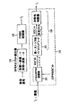
FECヘッダの配置は図1に示されており、ヘッダ情報を符号化する本発明の原理は、図2に従って部分的に達成される。図1は、次のFECフレームのために使用されるヘッダである、任意の次のFECヘッダと共に、図1におけるQAM変調されたLDPCパケットとしてラベル付けされる現在のFECフレームのFECヘッダの配置を示す。また、FECヘッダの変調順序は、FECフレームデータ部分の変調順序に基づくように適合される。例として、FECフレームが16-QAM又は64-QAMの何れかで変調される場合、BPSKは、FECヘッダの変調のために使用することができる。FECフレームが256-QAM、1K-QAM、又は4K-QAMの何れかで変調される場合、QPSKは、FECヘッダのための変調として使用することができる。 The arrangement of the FEC header is shown in FIG. 1, and the principle of the present invention for encoding header information is partially achieved according to FIG. FIG. 1 shows the FEC header placement of the current FEC frame labeled as a QAM modulated LDPC packet in FIG. 1, along with an optional next FEC header, which is the header used for the next FEC frame. Show. Also, the modulation order of the FEC header is adapted to be based on the modulation order of the FEC frame data portion. As an example, if the FEC frame is modulated with either 16-QAM or 64-QAM, BPSK can be used for modulation of the FEC header. If the FEC frame is modulated with either 256-QAM, 1K-QAM, or 4K-QAM, QPSK can be used as modulation for the FEC header.
図2は、FECヘッダの16シグナリングビットが、16-QAM又は64-QAM変調されたFECフレームの何れかについて本発明を使用してどのように更に符号化することができるかを示す。FECヘッダの16のシグナリングビットは、はじめに、たとえばReed-Muller(32,16)符号化によりFEC符号化される。Reed-Muller(32,16)符号化の出力である32コードワードのビットは、擬似ランダムバイナリ系列の32ビットに従ってオフセットBPSKにより変調される。この処理により、32のオフセットBPSKシンボルが得られる。高い信号対雑音比の環境では、FECヘッダ符号化のためにオフセットQPSK変調を使用することができ、16シンボルのみが得られる。 FIG. 2 shows how the 16 signaling bits of the FEC header can be further encoded using the present invention for either 16-QAM or 64-QAM modulated FEC frames. The 16 signaling bits of the FEC header are first FEC encoded by, for example, Reed-Muller (32, 16) encoding. The bits of the 32 code words that are the output of Reed-Muller (32, 16) encoding are modulated by the offset BPSK according to 32 bits of the pseudo random binary sequence. By this process, 32 offset BPSK symbols are obtained. In a high signal to noise ratio environment, offset QPSK modulation can be used for FEC header coding, and only 16 symbols are obtained.
図3は、オフセットBPSKのケースについてFECヘッダの検出を例示する。受信された信号は、その出力がPRBS相関器320により擬似ランダムバイナリ系列と相互の関係が比較されるBPSKオフセット検出器310で復調される。相互の関係の比較により閾値よりも高い場合、Reed-Mullerの対称性の検出330が実行される。閾値は、BPSK変調信号の良好な相関の性能を示す経験的証拠となる値に基づいて選択される。Reed-Muller(32,16)符号は、二次のReed-Muller符号であり、そのコードワードは、一次のReed-Muller符号とは異なり、対称的な構造を有さない。Reed-Muller(32,16)符号の復号化は、マジョリティデコーディングからなる3つのステージから構成され、第一のステージ335の後に、変更されたコードワードは、一次のReed-Muller符号のような対称的な構造を有する。この対称性の構造は、FECヘッダを検出するのに役立つために使用することができる。擬似ランダムバイナリ系列の相関332と、Reed-Muller対称性の相関338の結果は、復号判定を行うために結合される。
FIG. 3 illustrates FEC header detection for the case of offset BPSK. The received signal is demodulated by a BPSK offset
シミュレーションの結果は、BPSK変調によるReed-Muller(32,16)符号の使用は、加法性白色ガウス雑音(AWGN)チャネルにおいて10dBのSNRで信号伝達するFECヘッダについて誤りのない結果を達成することができることを示している。マジョリティデコーディングは、非常に低い複雑度を有しており、同様にシンプルなデコーダにつながる。 Simulation results show that the use of Reed-Muller (32,16) codes with BPSK modulation achieves error-free results for FEC headers signaling with an SNR of 10 dB in an additive white Gaussian noise (AWGN) channel It shows what you can do. Majority decoding has a very low complexity and leads to a simple decoder as well.
本実施の形態は、例としてDVB-C2の16ビットヘッダに適用される本発明の原理を例示する。本実施の形態で明示的に記載又は図示されていないが、本発明の原理を実施するアレンジメントであって、本発明の精神及び範囲に含まれる様々なアレンジメントを当業者であれば創作することを理解されたい。本発明の原理は、本発明の方法及び装置の適切な変更による異なる長さのヘッダ情報に同様に適用可能である。 This embodiment exemplifies the principle of the present invention applied to a DVB-C2 16-bit header as an example. Although not explicitly described or illustrated in the present embodiment, those skilled in the art will create various arrangements that implement the principles of the present invention and that fall within the spirit and scope of the present invention. I want you to understand. The principles of the present invention are equally applicable to header information of different lengths by appropriate modification of the method and apparatus of the present invention.
図4は、FECフレームヘッダを符号化する方法を例示する。符号化は、FEC符号化ステップ410により実行される。この符号化は、たとえばReed-Muller(32,16)符号化とすることができる。このステップに続いて、変調ステップ420は、擬似ランダムバイナリ系列を使用して、符号化されたヘッダ出力の変調を実行する。ステップ420により実行された変調は、たとえばBPSK又はQPSKとすることができる。
FIG. 4 illustrates a method for encoding an FEC frame header. Encoding is performed by
図5は、FECフレームヘッダを符号化する装置を例示する。FECエンコーダ510は、Reed-Muller(32,16)符号化のような入力FECフレームヘッダの符号化を実行するために使用される。符号化ブロック510の出力は、変調ブロック520に供給される。変調ブロック520は、擬似ランダムバイナリ系列を使用してFEC符号化されたフレームヘッダの値の変調を実行するために使用される。変調は、たとえばBPSK又はQPSKとすることができる。
FIG. 5 illustrates an apparatus for encoding an FEC frame header. The
図6は、FECフレームヘッダを検出する方法を例示する。ステップ610は、ヘッダ情報を受信する。次いで、ヘッダは、たとえばBPSKオフセット検出器によりステップ620で復調される。ステップ630で、復調されたヘッダ出力は、擬似ランダムバイナリ系列と相互の関係が比較される。次いで、この比較の結果は、ステップ640である閾値と比較される。比較結果が閾値よりも大きい場合、対称性の検出は、ステップ650で実行される。比較の結果が閾値よりも大きくない場合、プロセスは、ヘッダ情報を受信することで再び初期化される。
FIG. 6 illustrates a method for detecting an FEC frame header. Step 610 receives header information. The header is then demodulated at
図7は、本発明の原理を使用してヘッダ情報を復号化する装置を例示する。受信ブロック710は、ヘッダ情報を受信する。受信されたヘッダは、受信されたヘッダ情報を復調する復調ブロック720に入力される。相関ブロック730は、擬似バイナリ系列と復調された受信されたヘッダ情報の相互の関係を比較して、比較結果を生成するために使用される。比較ブロック740は、比較結果と選択された閾値とを比較する。対称性検出ブロック750は、比較結果が閾値よりも大きい場合に、復調された受信されたヘッダ情報を検出する。
FIG. 7 illustrates an apparatus for decoding header information using the principles of the present invention. The
本実施の形態で記載された全ての例及び条件付き言語は、本発明及び当該技術分野を発展させるために本発明者により寄与される概念を読者が理解するのを支援することが意図され、係る特に記載された例及び条件に限定されるものとして解釈されるべきではない。 All examples and conditional languages described in this embodiment are intended to help the reader understand the concepts contributed by the inventor to develop the invention and the art, It should not be construed as limited to such specifically described examples and conditions.
さらに、本発明の特定の例と同様に、本発明の原理、態様及び実施の形態を記載する全ての説明は、本発明の構造的及び機能的に等価なものを包含することが意図される。さらに、係る等価なものは、現在知られているものと同様に、将来に開発される等価なもの、すなわち構造に係らず同じ機能を実行する開発されたエレメントを含むことが意図される。 Further, as with the specific examples of the present invention, all descriptions describing the principles, aspects and embodiments of the present invention are intended to encompass the structural and functional equivalents of the present invention. . Moreover, such equivalents are intended to include equivalents developed in the future, i.e., elements that have been developed that perform the same function regardless of structure, as are currently known.
従って、たとえば、本実施の形態で与えられたブロック図は、本発明の原理を実施する例示的な回路の概念図を表すことが当業者により理解されるであろう。同様に、任意のフローチャート、フローダイアグラム、状態遷移図、擬似コード等は、コンピュータ読み取り可能な記録媒体で実質的に表され、コンピュータ又はプロセッサが明示的に図示されているか否かに係らず、係るコンピュータ又はプロセッサにより実行される様々な処理を表すことを理解されたい。 Thus, for example, it will be understood by those skilled in the art that the block diagram provided in the present embodiment represents a conceptual diagram of an exemplary circuit implementing the principles of the present invention. Similarly, any flowcharts, flow diagrams, state transition diagrams, pseudocodes, etc. may be substantially represented by computer-readable storage media, regardless of whether the computer or processor is explicitly illustrated. It should be understood that it represents various processes performed by a computer or processor.
図示される様々なエレメントの機能は、適切なソフトウェアと関連するソフトウェアを実行可能なハードウェアと同様に専用ソフトウェアの使用により提供される場合がある。プロセッサにより提供されるとき、機能は、1つの専用プロセッサ、1つの共有されるプロセッサ、又はそのうちの幾つかが共有される複数の個々のプロセッサにより提供される場合がある。さらに、用語「プロセッサ」又は「コントローラ」の明示的な使用は、ソフトウェアを実行可能なハードウェアを排他的に示すものと解釈されるべきではなく、限定されるものではないが、デジタルシグナルプロセッサ(DSP)ハードウェア、ソフトウェアを記憶するリードオンリメモリ(ROM)、ランダムアクセスメモリ(RAM)、及び不揮発性ストレージを暗黙的に含む場合がある。 The functionality of the various elements shown may be provided through the use of dedicated software as well as hardware capable of executing software associated with the appropriate software. When provided by a processor, the functionality may be provided by one dedicated processor, one shared processor, or multiple individual processors some of which are shared. Furthermore, the explicit use of the term “processor” or “controller” should not be construed to represent exclusively hardware capable of executing software, but is not limited to digital signal processors ( It may implicitly include DSP) hardware, read only memory (ROM) storing software, random access memory (RAM), and non-volatile storage.
コンベンショナル及び/又はカスタムの他のハードウェアが含まれる場合もある。同様に、図示される任意のスイッチは概念的なものである。それらの機能は、プログラムロジックの動作を通して、専用ロジックの動作を通して、プログラム制御と専用ロジックとの相互作用を通して、或いは手動的に実行される場合があり、特定の技術は、コンテキストから詳細に理解されるように、実現者により選択可能である。 Other conventional and / or custom hardware may also be included. Similarly, any switches shown are conceptual. These functions may be performed through the operation of program logic, through the operation of dedicated logic, through the interaction of program control and dedicated logic, or manually, and the specific techniques are understood in detail from the context. As can be selected by the implementer.
本発明の請求項では、特定の機能を実行する手段として表現されるエレメントは、たとえばa)その機能を実行する回路エレメントの組み合わせ、又はb)機能を実行するソフトウェアを実行する適切な回路と結合される、ファームウェア、マイクロプロセッサ等を含む任意の形式でのソフトウェア、を含むその機能を実行する方法を包含することが意図される。係る請求項により定義される本発明の原理は、様々な記載された手段により提供される機能が請求項が求める方法と共に結合され、纏められる事実にある。それら機能を提供する任意の手段は本実施の形態で示された手段と等価であるとみなされる。 In the claims of the present invention, an element expressed as a means for performing a specific function is combined with, for example, a) a combination of circuit elements that perform that function, or b) a suitable circuit that executes software that performs the function. It is intended to encompass methods of performing its functions including any form of software, including firmware, microprocessors, etc. The principle of the invention as defined by such claims resides in the fact that the functions provided by the various described means are combined and grouped together with the methods required by the claims. Any means for providing these functions is considered equivalent to the means shown in this embodiment.
本発明の原理の「1実施の形態」又は「実施の形態」に対する明細書における参照は、本発明の他の変形例と同様に、実施の形態と共に記載される特定の特徴、構造、特徴等が本発明の少なくとも1つの実施の形態に含まれることを意味する。従って、明細書を通して様々な位置に現れる他の変形と同様に、記載「1実施の形態では」又は「実施の形態では」の出現は、同じ実施の形態を必ずしも示すものではない。 References in the specification to “one embodiment” or “an embodiment” of the principles of the invention are specific features, structures, features, etc. described with the embodiments, as well as other variations of the invention. Is included in at least one embodiment of the present invention. Thus, like other variations appearing at various locations throughout the specification, the appearance of the description “in one embodiment” or “in an embodiment” does not necessarily indicate the same embodiment.
Claims (6)
Reed-Muller符号化を使用してデジタルケーブルテレビ環境でデータパケットのヘッダビットを符号化するステップと、
前記Reed-Muller符号化の出力を擬似ランダムバイナリ系列で変調するステップとを含み、
前記擬似ランダムバイナリ系列は、オフセット変調方式の別個のオフセット位相を選択するために使用され、
前記変調するステップにおける変調オーダーは、前記ヘッダ情報に対応するデータ部分のために使用される変調オーダーに基づいて適合され、
16-QAM又は64-QAMが前記データパケットの前記データ部分のために使用されるときに、オフセット二相位相シフトキーイングの位相を制御して前記ヘッダ情報を変調するために前記擬似ランダムバイナリ系列が使用され、
256-QAM、1K-QAM又は4K-QAMが前記データパケットの前記データ部分のために使用されるときに、オフセット直交位相シフトキーイングの位相を制御して前記ヘッダ情報を変調するために前記擬似ランダムバイナリ系列が使用される方法。 A method performed by an apparatus for encoding header information,
Encoding header bits of a data packet in a digital cable television environment using Reed-Muller encoding;
Modulating the output of the Reed-Muller encoding with a pseudo-random binary sequence,
The pseudo-random binary sequence is used to select a separate offset phase of an offset modulation scheme;
The modulation order in the modulating step is adapted based on the modulation order used for the data portion corresponding to the header information;
When 16-QAM or 64-QAM is used for the data portion of the data packet, the pseudo-random binary sequence is used to modulate the header information by controlling the phase of offset binary phase shift keying. Used,
When 256-QAM, 1K-QAM or 4K-QAM is used for the data portion of the data packet, the pseudo-random to control the phase of offset quadrature phase shift keying to modulate the header information how to binary sequence Ru is used.
Reed-Muller符号化を使用してデジタルケーブルテレビ環境でデータパケットのヘッダビットを符号化するReed-Mullerエンコーダと、
前記Reed-Muller符号化の出力を擬似ランダムバイナリ系列で変調する変調器とを備え、
前記擬似ランダムバイナリ系列は、オフセット変調方式の別個のオフセット位相を選択するために使用され、
前記変調器による変調オーダーは、前記ヘッダ情報に対応するデータ部分のために使用される変調オーダーに基づいて適合され、
16-QAM又は64-QAMが前記データパケットの前記データ部分のために使用されるときに、オフセット二相位相シフトキーイングの位相を制御して前記ヘッダ情報を変調するために前記擬似ランダムバイナリ系列が使用され、
256-QAM、1K-QAM又は4K-QAMが前記データパケットの前記データ部分のために使用されるときに、オフセット直交位相シフトキーイングの位相を制御して前記ヘッダ情報を変調するために前記擬似ランダムバイナリ系列が使用される装置。 An apparatus for encoding header information,
A Reed-Muller encoder that encodes the header bits of a data packet in a digital cable television environment using Reed-Muller encoding;
A modulator that modulates the output of the Reed-Muller encoding with a pseudo-random binary sequence,
The pseudo-random binary sequence is used to select a separate offset phase of an offset modulation scheme;
The modulation order by the modulator is adapted based on the modulation order used for the data portion corresponding to the header information;
When 16-QAM or 64-QAM is used for the data portion of the data packet, the pseudo-random binary sequence is used to modulate the header information by controlling the phase of offset binary phase shift keying. Used,
When 256-QAM, 1K-QAM or 4K-QAM is used for the data portion of the data packet, the pseudo-random to control the phase of offset quadrature phase shift keying to modulate the header information device binary sequence Ru is used.
デジタルケーブルテレビ環境でデータパケットのヘッダ情報を受信するステップと、
受信されたヘッダ情報を復調するステップとを含み、
オフセット変調方式の別個のオフセット位相を選択するために擬似ランダムバイナリ系列が使用され、
前記復調するステップにおける復調オーダーは、前記ヘッダ情報に対応するデータ部分のために使用される変調オーダーに基づいて適合され、16-QAM又は64-QAMが前記データパケットの前記データ部分のために使用されるときに、オフセット二相位相シフトキーイングの位相を制御して前記ヘッダ情報を復調するために前記擬似ランダムバイナリ系列が使用され、256-QAM、1K-QAM又は4K-QAMが前記データパケットの前記データ部分のために使用されるときに、オフセット直交位相シフトキーイングの位相を制御して前記ヘッダ情報を復調するために前記擬似ランダムバイナリ系列が使用され、
復調された受信されたヘッダ情報を前記擬似ランダムバイナリ系列と関連付けして相関結果を生成するステップと、
復調された受信されたヘッダ情報に二次Reed-Muller符号のReed-Muller復号化を条件付きで実行するステップとを更に含み、
前記条件は、前記相関結果が閾値より大きい場合である方法。 A method performed by a device for decoding header information,
Receiving data packet header information in a digital cable television environment;
Demodulating received header information ,
A pseudo-random binary sequence is used to select a separate offset phase of the offset modulation scheme;
The demodulation order in the demodulating step is adapted based on the modulation order used for the data portion corresponding to the header information, and 16-QAM or 64-QAM is used for the data portion of the data packet. when it is, the pseudo-random binary sequence is used to demodulate the header information by controlling the phase of the offset binary phase shift keying, 256-QAM, 1K-QAM or 4K-QAM is the data packet When used for the data portion, the pseudo-random binary sequence is used to control the phase of offset quadrature phase shift keying to demodulate the header information;
Associating demodulated received header information with the pseudo-random binary sequence to generate a correlation result;
Conditionally performing Reed-Muller decoding of a secondary Reed-Muller code on the demodulated received header information ;
The method is a method in which the correlation result is larger than a threshold value .
デジタルケーブルテレビ環境でデータパケットのヘッダ情報を受信する受信手段と、
受信されたヘッダ情報を復調する復調手段とを備え、
オフセット変調方式の別個のオフセット位相を選択するために擬似ランダムバイナリ系列が使用され、
前記復調手段による復調オーダーは、前記ヘッダ情報に対応するデータ部分のために使用される変調オーダーに基づいて適合され、16-QAM又は64-QAMが前記データパケットの前記データ部分のために使用されるときに、オフセット二相位相シフトキーイングの位相を制御して前記ヘッダ情報を復調するために前記擬似ランダムバイナリ系列が使用され、256-QAM、1K-QAM又は4K-QAMが前記データパケットの前記データ部分のために使用されるときに、オフセット直交位相シフトキーイングの位相を制御して前記ヘッダ情報を復調するために前記擬似ランダムバイナリ系列が使用され、
復調された受信されたヘッダ情報を前記擬似ランダムバイナリ系列と関連付けして相関結果を生成する相関手段と、
復調された受信されたヘッダ情報にReed-Muller復号化を条件付きで実行する二次Reed-Muller符号のReed-Muller復号化手段とを更に備え、
前記条件は、前記相関結果が閾値より大きい場合である装置。 An apparatus for decoding header information,
Receiving means for receiving data packet header information in a digital cable television environment;
Demodulation means for demodulating the received header information ,
A pseudo-random binary sequence is used to select a separate offset phase of the offset modulation scheme;
The demodulation order by the demodulation means is adapted based on the modulation order used for the data portion corresponding to the header information, and 16-QAM or 64-QAM is used for the data portion of the data packet. the Rutoki, said pseudo-random binary sequence to demodulate said header information is used to control the offset binary phase shift keying phase, the 256-QAM, the 1K-QAM or 4K-QAM of the data packet When used for the data portion, the pseudo-random binary sequence is used to control the phase of offset quadrature phase shift keying to demodulate the header information;
Correlation means for associating demodulated received header information with the pseudo-random binary sequence to generate a correlation result;
Reed-Muller decoding means for secondary Reed-Muller code that conditionally executes Reed-Muller decoding on demodulated received header information ,
The condition is an apparatus in which the correlation result is larger than a threshold value .
Applications Claiming Priority (3)
| Application Number | Priority Date | Filing Date | Title |
|---|---|---|---|
| US11512308P | 2008-11-17 | 2008-11-17 | |
| US61/115,123 | 2008-11-17 | ||
| PCT/US2009/006138 WO2010056363A1 (en) | 2008-11-17 | 2009-11-17 | Fec frame header design for cable television signals |
Publications (3)
| Publication Number | Publication Date |
|---|---|
| JP2012509613A JP2012509613A (en) | 2012-04-19 |
| JP2012509613A5 JP2012509613A5 (en) | 2013-01-10 |
| JP5628189B2 true JP5628189B2 (en) | 2014-11-19 |
Family
ID=41572441
Family Applications (1)
| Application Number | Title | Priority Date | Filing Date |
|---|---|---|---|
| JP2011536335A Expired - Fee Related JP5628189B2 (en) | 2008-11-17 | 2009-11-17 | Forward error correction frame header design for cable television signals |
Country Status (7)
| Country | Link |
|---|---|
| US (1) | US9350489B2 (en) |
| EP (1) | EP2356787B1 (en) |
| JP (1) | JP5628189B2 (en) |
| KR (1) | KR20110091545A (en) |
| CN (1) | CN102217263B (en) |
| BR (1) | BRPI0921808A2 (en) |
| WO (1) | WO2010056363A1 (en) |
Families Citing this family (8)
| Publication number | Priority date | Publication date | Assignee | Title |
|---|---|---|---|---|
| KR101737106B1 (en) * | 2009-06-29 | 2017-05-17 | 톰슨 라이센싱 | Method and apparatus for robust and high efficiency fec frame header recovery |
| US8744010B2 (en) | 2011-05-12 | 2014-06-03 | Nokia Corporation | Providing signaling information in an electronic service guide |
| US9584238B2 (en) * | 2011-06-24 | 2017-02-28 | Nokia Corporation | Accessing service guide information in a digital video broadcast system |
| CN103179065B (en) * | 2011-12-21 | 2017-03-29 | 北京普源精电科技有限公司 | Offset quadrature phase-shift-keying modulator approach, device and digital signal generator |
| CN107241188B (en) * | 2017-06-02 | 2022-01-28 | 丁爱民 | Quantum storage data encoding and decoding method, device and system |
| CN114079534B (en) * | 2020-08-20 | 2023-03-28 | 腾讯科技(深圳)有限公司 | Encoding method, decoding method, apparatus, medium, and electronic device |
| CN113965244B (en) * | 2021-09-30 | 2023-05-30 | 西南电子技术研究所(中国电子科技集团公司第十研究所) | Satellite communication variable code modulation fractional frame processing method |
| CN114666024A (en) * | 2022-03-11 | 2022-06-24 | 成都中科微信息技术研究院有限公司 | Reverse signaling retransmission method and communication system based on DVB protocol |
Family Cites Families (34)
| Publication number | Priority date | Publication date | Assignee | Title |
|---|---|---|---|---|
| JPH09181618A (en) | 1995-12-27 | 1997-07-11 | Nec Corp | Data transmitter |
| US6211919B1 (en) * | 1997-03-28 | 2001-04-03 | Tektronix, Inc. | Transparent embedment of data in a video signal |
| US6031865A (en) | 1997-08-04 | 2000-02-29 | Motorola, Inc. | Rapidly decorrelating spreading sequences for DS-CDMA transceivers |
| US6590889B1 (en) * | 1997-08-11 | 2003-07-08 | Gte Internetworking Incorporated | Data communications system and hybrid time-code multiplexing method |
| US6426978B1 (en) | 1998-10-01 | 2002-07-30 | Ericsson Inc. | Digital communication systems and methods for differential and/or amplitude encoding and decoding secondary symbols |
| US6868075B1 (en) * | 1999-09-28 | 2005-03-15 | Telefonaktiebolaget Lm Ericsson (Publ) | Method and apparatus for compressed mode communications over a radio interface |
| AU5999301A (en) * | 2000-05-25 | 2001-12-03 | Soma Networks Inc | Quality dependent data communication channel |
| US6865236B1 (en) * | 2000-06-01 | 2005-03-08 | Nokia Corporation | Apparatus, and associated method, for coding and decoding multi-dimensional biorthogonal codes |
| KR100421164B1 (en) | 2000-06-12 | 2004-03-04 | 삼성전자주식회사 | Apparatus and method for encoding and decoding tfci in a mobile communication system |
| US7313192B2 (en) * | 2001-05-31 | 2007-12-25 | Nxp B.V. | Method and apparatus for a complementary encoder/decoder |
| CN1151677C (en) | 2001-08-17 | 2004-05-26 | 清华大学 | Cascade error-correcting coder and its coding method |
| JP2003158519A (en) * | 2001-11-22 | 2003-05-30 | Canon Inc | Method and apparatus for cryptographing quantum state and quantum information |
| US8208499B2 (en) * | 2003-06-13 | 2012-06-26 | Dtvg Licensing, Inc. | Framing structure for digital broadcasting and interactive services |
| CA2470546C (en) | 2003-06-13 | 2010-08-17 | The Directv Group, Inc. | Method and apparatus for providing carrier synchronization in digital broadcast and interactive systems |
| US7352797B2 (en) | 2003-06-30 | 2008-04-01 | Conexant Systems, Inc. | Procedure for BPSK modulation with reduced envelope peaking |
| CN1213573C (en) | 2003-07-18 | 2005-08-03 | 清华大学 | Physical layer encryption method based on time-varying MPSK modulation in wireless local area network |
| US7356089B2 (en) * | 2003-09-05 | 2008-04-08 | Nortel Networks Limited | Phase offset spatial multiplexing |
| DE602004011445T2 (en) * | 2003-11-03 | 2009-01-15 | Broadcom Corp., Irvine | FEC decoding with dynamic parameters |
| JP4359877B2 (en) | 2004-01-20 | 2009-11-11 | 日本ビクター株式会社 | OFDM signal modulation apparatus and OFDM signal modulation method |
| JP2005260611A (en) | 2004-03-11 | 2005-09-22 | Sanyo Electric Co Ltd | Transmitting method and device, and receiving method and device |
| JP2005260600A (en) | 2004-03-11 | 2005-09-22 | Nippon Dempa Kogyo Co Ltd | Crystal oscillator for surface mounting |
| EP1762021A1 (en) * | 2004-09-15 | 2007-03-14 | Samsung Electronics Co., Ltd. | Method and apparatus for encoding/decoding transmission information in mobile telecommunication system |
| FR2892245B1 (en) | 2005-10-14 | 2008-04-04 | Cnes Epic | METHOD FOR RECEIVING FRAMES OF A DIGITAL STREAM |
| US7715786B2 (en) * | 2006-02-08 | 2010-05-11 | The Directv Group, Inc. | Blind identification of advanced modulation and coding modes |
| US7627058B2 (en) | 2006-03-28 | 2009-12-01 | Teledyne Licensing Llc | Alternating quadratures differential binary phase shift keying modulation and demodulation method |
| WO2007148863A1 (en) | 2006-06-20 | 2007-12-27 | Lg Electronics Inc. | Digital broadcasting system and method of processing data |
| CN101150574B (en) | 2006-09-18 | 2012-05-30 | 国家广播电影电视总局广播科学研究院 | Valid frame structure of digital satellite communication |
| US8306060B2 (en) * | 2006-11-07 | 2012-11-06 | Samsung Electronics Co., Ltd. | System and method for wireless communication of uncompressed video having a composite frame format |
| GB0625851D0 (en) * | 2006-12-22 | 2007-02-07 | Isis Innovation | Improvements in communications security |
| JP5003177B2 (en) | 2007-01-26 | 2012-08-15 | ソニー株式会社 | Transmitting apparatus, receiving apparatus, packet transmitting method, packet receiving method, and program |
| JP4913641B2 (en) | 2007-03-20 | 2012-04-11 | 株式会社エヌ・ティ・ティ・ドコモ | Base station, communication terminal, transmission method, reception method, communication system |
| US8238436B2 (en) | 2007-03-30 | 2012-08-07 | Mediatek Inc. | Methods and device for fast acquisition of digital video signals |
| JP4324886B2 (en) * | 2007-04-27 | 2009-09-02 | ソニー株式会社 | Frame synchronization apparatus and method, and demodulation apparatus |
| CN101222290B (en) | 2007-11-09 | 2013-01-02 | 北京创毅视讯科技有限公司 | Data transmission method, emission system and terminal in broadcasting system |
-
2009
- 2009-11-17 WO PCT/US2009/006138 patent/WO2010056363A1/en active Application Filing
- 2009-11-17 JP JP2011536335A patent/JP5628189B2/en not_active Expired - Fee Related
- 2009-11-17 KR KR1020117013826A patent/KR20110091545A/en not_active Application Discontinuation
- 2009-11-17 CN CN200980145671.4A patent/CN102217263B/en not_active Expired - Fee Related
- 2009-11-17 US US12/998,660 patent/US9350489B2/en not_active Expired - Fee Related
- 2009-11-17 EP EP09796146.0A patent/EP2356787B1/en not_active Not-in-force
- 2009-11-17 BR BRPI0921808A patent/BRPI0921808A2/en not_active IP Right Cessation
Also Published As
| Publication number | Publication date |
|---|---|
| CN102217263A (en) | 2011-10-12 |
| CN102217263B (en) | 2015-06-03 |
| WO2010056363A1 (en) | 2010-05-20 |
| JP2012509613A (en) | 2012-04-19 |
| BRPI0921808A2 (en) | 2018-06-05 |
| EP2356787B1 (en) | 2017-10-04 |
| US20110222610A1 (en) | 2011-09-15 |
| EP2356787A1 (en) | 2011-08-17 |
| KR20110091545A (en) | 2011-08-11 |
| US9350489B2 (en) | 2016-05-24 |
Similar Documents
| Publication | Publication Date | Title |
|---|---|---|
| US8887030B2 (en) | Encoder and encoding method providing incremental redundancy | |
| US10250358B2 (en) | Transmitter and receiver for transmitting basic codeword portion and auxiliary codeword portion of a codeword in different frames | |
| US9385752B2 (en) | Encoder and encoding method providing incremental redundancy | |
| JP5628189B2 (en) | Forward error correction frame header design for cable television signals | |
| JP5804562B2 (en) | Encoding method and apparatus | |
| US10965396B2 (en) | Receiver for receiving data in a broadcast system using redundancy data | |
| WO2014082997A1 (en) | Receiver for receiving data in a broadcast system | |
| WO2014082933A1 (en) | Control device and method for use in a broadcast system | |
| TWI508504B (en) | Receiver and receiving method for receiving data in a broadcasting system using incremental redundancy | |
| WO2010056357A2 (en) | Fec frame header design for cable television signals | |
| WO2010065100A2 (en) | Method and apparatus for transmitting and receiving fec frame headers | |
| WO2011104144A1 (en) | Encoder and encoding method providing incremental redundancy |
Legal Events
| Date | Code | Title | Description |
|---|---|---|---|
| A521 | Written amendment |
Free format text: JAPANESE INTERMEDIATE CODE: A523 Effective date: 20121116 |
|
| A621 | Written request for application examination |
Free format text: JAPANESE INTERMEDIATE CODE: A621 Effective date: 20121116 |
|
| A131 | Notification of reasons for refusal |
Free format text: JAPANESE INTERMEDIATE CODE: A131 Effective date: 20130903 |
|
| A601 | Written request for extension of time |
Free format text: JAPANESE INTERMEDIATE CODE: A601 Effective date: 20131202 |
|
| A602 | Written permission of extension of time |
Free format text: JAPANESE INTERMEDIATE CODE: A602 Effective date: 20131209 |
|
| A521 | Written amendment |
Free format text: JAPANESE INTERMEDIATE CODE: A523 Effective date: 20140228 |
|
| TRDD | Decision of grant or rejection written | ||
| A01 | Written decision to grant a patent or to grant a registration (utility model) |
Free format text: JAPANESE INTERMEDIATE CODE: A01 Effective date: 20140902 |
|
| A61 | First payment of annual fees (during grant procedure) |
Free format text: JAPANESE INTERMEDIATE CODE: A61 Effective date: 20141001 |
|
| R150 | Certificate of patent or registration of utility model |
Ref document number: 5628189 Country of ref document: JP Free format text: JAPANESE INTERMEDIATE CODE: R150 |
|
| LAPS | Cancellation because of no payment of annual fees |