JP5627394B2 - Program for determining mask data and exposure conditions, determination method, mask manufacturing method, exposure method, and device manufacturing method - Google Patents
Program for determining mask data and exposure conditions, determination method, mask manufacturing method, exposure method, and device manufacturing method Download PDFInfo
- Publication number
- JP5627394B2 JP5627394B2 JP2010244368A JP2010244368A JP5627394B2 JP 5627394 B2 JP5627394 B2 JP 5627394B2 JP 2010244368 A JP2010244368 A JP 2010244368A JP 2010244368 A JP2010244368 A JP 2010244368A JP 5627394 B2 JP5627394 B2 JP 5627394B2
- Authority
- JP
- Japan
- Prior art keywords
- pattern
- parameter
- mask
- main pattern
- image
- Prior art date
- Legal status (The legal status is an assumption and is not a legal conclusion. Google has not performed a legal analysis and makes no representation as to the accuracy of the status listed.)
- Active
Links
Images


Classifications
-
- G—PHYSICS
- G03—PHOTOGRAPHY; CINEMATOGRAPHY; ANALOGOUS TECHNIQUES USING WAVES OTHER THAN OPTICAL WAVES; ELECTROGRAPHY; HOLOGRAPHY
- G03F—PHOTOMECHANICAL PRODUCTION OF TEXTURED OR PATTERNED SURFACES, e.g. FOR PRINTING, FOR PROCESSING OF SEMICONDUCTOR DEVICES; MATERIALS THEREFOR; ORIGINALS THEREFOR; APPARATUS SPECIALLY ADAPTED THEREFOR
- G03F1/00—Originals for photomechanical production of textured or patterned surfaces, e.g., masks, photo-masks, reticles; Mask blanks or pellicles therefor; Containers specially adapted therefor; Preparation thereof
- G03F1/36—Masks having proximity correction features; Preparation thereof, e.g. optical proximity correction [OPC] design processes
-
- G—PHYSICS
- G03—PHOTOGRAPHY; CINEMATOGRAPHY; ANALOGOUS TECHNIQUES USING WAVES OTHER THAN OPTICAL WAVES; ELECTROGRAPHY; HOLOGRAPHY
- G03F—PHOTOMECHANICAL PRODUCTION OF TEXTURED OR PATTERNED SURFACES, e.g. FOR PRINTING, FOR PROCESSING OF SEMICONDUCTOR DEVICES; MATERIALS THEREFOR; ORIGINALS THEREFOR; APPARATUS SPECIALLY ADAPTED THEREFOR
- G03F7/00—Photomechanical, e.g. photolithographic, production of textured or patterned surfaces, e.g. printing surfaces; Materials therefor, e.g. comprising photoresists; Apparatus specially adapted therefor
- G03F7/70—Microphotolithographic exposure; Apparatus therefor
- G03F7/70058—Mask illumination systems
- G03F7/70125—Use of illumination settings tailored to particular mask patterns
-
- G—PHYSICS
- G03—PHOTOGRAPHY; CINEMATOGRAPHY; ANALOGOUS TECHNIQUES USING WAVES OTHER THAN OPTICAL WAVES; ELECTROGRAPHY; HOLOGRAPHY
- G03F—PHOTOMECHANICAL PRODUCTION OF TEXTURED OR PATTERNED SURFACES, e.g. FOR PRINTING, FOR PROCESSING OF SEMICONDUCTOR DEVICES; MATERIALS THEREFOR; ORIGINALS THEREFOR; APPARATUS SPECIALLY ADAPTED THEREFOR
- G03F7/00—Photomechanical, e.g. photolithographic, production of textured or patterned surfaces, e.g. printing surfaces; Materials therefor, e.g. comprising photoresists; Apparatus specially adapted therefor
- G03F7/70—Microphotolithographic exposure; Apparatus therefor
- G03F7/70425—Imaging strategies, e.g. for increasing throughput or resolution, printing product fields larger than the image field or compensating lithography- or non-lithography errors, e.g. proximity correction, mix-and-match, stitching or double patterning
- G03F7/70433—Layout for increasing efficiency or for compensating imaging errors, e.g. layout of exposure fields for reducing focus errors; Use of mask features for increasing efficiency or for compensating imaging errors
- G03F7/70441—Optical proximity correction [OPC]
-
- G—PHYSICS
- G03—PHOTOGRAPHY; CINEMATOGRAPHY; ANALOGOUS TECHNIQUES USING WAVES OTHER THAN OPTICAL WAVES; ELECTROGRAPHY; HOLOGRAPHY
- G03F—PHOTOMECHANICAL PRODUCTION OF TEXTURED OR PATTERNED SURFACES, e.g. FOR PRINTING, FOR PROCESSING OF SEMICONDUCTOR DEVICES; MATERIALS THEREFOR; ORIGINALS THEREFOR; APPARATUS SPECIALLY ADAPTED THEREFOR
- G03F7/00—Photomechanical, e.g. photolithographic, production of textured or patterned surfaces, e.g. printing surfaces; Materials therefor, e.g. comprising photoresists; Apparatus specially adapted therefor
- G03F7/70—Microphotolithographic exposure; Apparatus therefor
- G03F7/70483—Information management; Active and passive control; Testing; Wafer monitoring, e.g. pattern monitoring
- G03F7/70491—Information management, e.g. software; Active and passive control, e.g. details of controlling exposure processes or exposure tool monitoring processes
- G03F7/705—Modelling or simulating from physical phenomena up to complete wafer processes or whole workflow in wafer productions
Description
本発明は、マスクのデータを作成するためのプログラムに関する。 The present invention relates to a program for creating mask data.
IC、LSIなどの半導体デバイスの製造工程において露光装置が使用されている。露光装置は、マスク(レチクル)を照明装置で照明し、そのマスクに描画されたパターンの像を投影光学系を用いて基板(ウエハ)に投影して基板を露光する。 An exposure apparatus is used in the manufacturing process of semiconductor devices such as IC and LSI. The exposure apparatus illuminates a mask (reticle) with an illumination apparatus, and projects an image of a pattern drawn on the mask onto a substrate (wafer) using a projection optical system to expose the substrate.
露光装置の解像性能を向上させる手法として超解像技術がある。例えば、マスクに、自身は解像しない補助パターンを設けて、基板上に形成すべきパターンを解像する技術がある。補助パターンの配置等を設計する方法として、インターフェアレンスマップを利用する方法(非特許文献1)と、インバースリソグラフィー(非特許文献2)、特許文献1に記載の方法がある。
There is a super-resolution technique as a technique for improving the resolution performance of an exposure apparatus. For example, there is a technique for resolving a pattern to be formed on a substrate by providing a mask with an auxiliary pattern that does not resolve itself. As a method for designing the arrangement of the auxiliary pattern and the like, there are a method using an interference map (Non-Patent Document 1), inverse lithography (Non-Patent Document 2), and a method described in
しかし、非特許文献1では、パターン形状の最適化において、基板に転写されるべきメインパターンの形状と補助パターンの形状は別々に決定される。どちらの形状も基板上に投影される投影像に影響を与えるため、別々に決定する方法ではローカルミニマム(局所解)にトラップされやすく、マスクのパターンの最適な形状(最適解)が求まりにくい。または、最適解を求めるのに必要な計算量が増えてしまうという欠点があった。
However, in
また、特許文献1に記載の方法は、メインパターンと補助パターンを変形しながらマスクパターンを決定しているが、物理モデルに忠実に計算した厳密像ではなく、近似空中像を用いている。そして、その近似空中像のみに従ってマスクのパターンを決定しているため、最適化結果に誤差を生じる可能性があった。また、近似空中像は複雑な模様を示すため、マスクパターンが複雑な形状となるおそれがある。
In the method described in
非特許文献2のインバースリソグラフィーでは、メインパターンと補助パターンが一度に決定される。しかし、値が連続的に変化する複雑な模様を示す2次元のマップから、マスクパターンを作成するため、マスクのパターンが複雑になり、マスクの製造コストが高くなるという欠点があった。
In the inverse lithography of Non-Patent
そこで本発明は、解像性能とマスク製造コストの抑制とを両立できるマスクデータ作成プログラムや方法を提供することを目的とする。 Accordingly, an object of the present invention is to provide a mask data creation program and method that can achieve both resolution performance and mask manufacturing cost reduction.
本発明の一側面としてのプログラムは、マスクのパターンの像を基板に投影する投影光学系を用いて前記基板を露光する露光装置に用いられる前記マスクのデータおよび露光条件をコンピュータに決定させるプログラムであって、前記マスクのパターンとして、前記基板に形成すべき目標パターンを解像するためのメインパターンと前記メインパターンの解像を補助する補助パターンとを設定し、前記メインパターンのパラメータの値と、前記補助パターンのパラメータの値を設定する設定ステップと、前記マスクを照明する照明光学系の瞳面の光強度分布のパラメータの値を設定するステップと、該設定された前記メインパターンのパラメータおよび前記補助パターンのパラメータのそれぞれの値で定められる前記メインパターンおよび前記補助パターンを、該設定された前記照明光学系の瞳面の光強度分布で前記投影光学系を用いて投影した場合の前記メインパターンの像を計算する計算ステップと、該計算された前記メインパターンの像を評価する評価ステップとを前記コンピュータに実行させ、前記評価ステップにおける前記メインパターンの像の評価結果に基づいて前記メインパターンのパラメータの値、前記補助パターンのパラメータの値および前記照明光学系の瞳面の光強度分布のパラメータの値を変更する変更ステップと、前記変更ステップにおいて変更した後の前記メインパターンのパラメータの値、前記補助パターンのパラメータの値および前記照明光学系の瞳面の光強度分布のパラメータの値を用いて前記計算ステップ及び前記評価ステップを行うステップと、を繰り返し前記コンピュータに実行させ、当該繰り返しによって得られる前記メインパターンの像の評価結果に基づいて、前記メインパターンのパラメータの値、前記補助パターンのパラメータの値および前記照明光学系の瞳面の光強度分布のパラメータの値を前記コンピュータに決定させることを特徴とする。 A program according to one aspect of the present invention is a program that causes a computer to determine the mask data and exposure conditions used in an exposure apparatus that exposes the substrate using a projection optical system that projects an image of a mask pattern onto the substrate. And, as the mask pattern, a main pattern for resolving a target pattern to be formed on the substrate and an auxiliary pattern for assisting in the resolution of the main pattern are set, and the parameter value of the main pattern Setting a parameter value of the auxiliary pattern; setting a parameter value of a light intensity distribution parameter of a pupil plane of an illumination optical system that illuminates the mask; and the set main pattern parameter and The main pattern and the front defined by the respective values of the auxiliary pattern parameters A calculation step of calculating an image of the main pattern when the auxiliary pattern is projected using the projection optical system with the light intensity distribution of the pupil plane of the illumination optical system thus set, and the calculated main pattern An evaluation step for evaluating the image of the main pattern, and the main pattern parameter value, the auxiliary pattern parameter value, and the illumination optical system based on the evaluation result of the main pattern image in the evaluation step. A change step of changing a light intensity distribution parameter value of the pupil plane, a parameter value of the main pattern, a parameter value of the auxiliary pattern, and a pupil plane of the illumination optical system after the change in the change step Performing the calculation step and the evaluation step using values of parameters of the light intensity distribution Are repeatedly executed by the computer, and based on the evaluation result of the image of the main pattern obtained by the repetition, the parameter value of the main pattern, the parameter value of the auxiliary pattern, and the pupil plane of the illumination optical system The computer is configured to determine a value of a parameter of light intensity distribution .
本発明によれば、解像性能とマスク製造コストの抑制とを両立できるマスクデータ作成プログラムや方法を提供できる。 ADVANTAGE OF THE INVENTION According to this invention, the mask data creation program and method which can make resolution performance and suppression of mask manufacturing cost compatible can be provided.
以下に、本発明の好ましい実施例を添付の図面に基づいて詳細に説明する。 Hereinafter, preferred embodiments of the present invention will be described in detail with reference to the accompanying drawings.
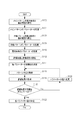
図1は、マスクのパターンを決定する際のフローチャートである。なお、各ステップを実行するためのプログラムをコンピュータにインストールして、該プログラムをコンピュータに実行させることによりマスクのパターンを求める。 FIG. 1 is a flowchart for determining a mask pattern. A program for executing each step is installed in a computer, and the mask pattern is obtained by causing the computer to execute the program.
第1の実施例では基板に転写すべきメインパターンと、基板に転写されない補助パターン(SRAF(Sub−Resolution Assist features)ともいう)の両方がマスク上に存在し、その両方のパターンの形状と位置とを決定する。さらに、メインパターンと補助パターンとを含むマスクのパターンの像をウエハ(基板)に投影してウエハを露光する場合の露光条件も決定する。 In the first embodiment, both a main pattern to be transferred to the substrate and an auxiliary pattern (also referred to as SRAF (Sub-Resolution Assist Features)) that are not transferred to the substrate exist on the mask, and the shape and position of both patterns. And decide. Further, the exposure condition for exposing the wafer by projecting an image of the mask pattern including the main pattern and the auxiliary pattern onto the wafer (substrate) is also determined.
本実施例のマスクパターンと露光条件の決定方法は、図1に示すように、まず、S102ではメインパターンの基本形状と基本配置とを設定する。例えば、基本形状は長方形や正方形など、基本配置は左右対称などを表す。S104では、メインパターンの形状と位置とを定めるためのパラメータを設定する。S106では、補助パターンの基本形状と基本配置とを設定する。S108では、補助パターンの形状と位置とを定めるためのパラメータを設定する。S110では、マスクのパターンの像をウエハに投影して露光するときの露光条件を表すパラメータを設定する。S112では、ウエハに投影されるパターンの像を評価する位置と評価項目を設定する。これらの設定は、ユーザーがデータを入力し、入力データをコンピュータ上で設定することにより行われてもよいし、プログラムに実装されたコードを実行することによりコンピュータで自動的に行ってもよい。 As shown in FIG. 1, in the determination method of the mask pattern and exposure conditions of this embodiment, first, in S102, the basic shape and basic arrangement of the main pattern are set. For example, the basic shape represents a rectangle or a square, and the basic arrangement represents left-right symmetry. In S104, parameters for determining the shape and position of the main pattern are set. In S106, the basic shape and basic arrangement of the auxiliary pattern are set. In S108, parameters for determining the shape and position of the auxiliary pattern are set. In step S110, parameters representing exposure conditions when the mask pattern image is projected onto the wafer for exposure are set. In S112, a position and an evaluation item for evaluating a pattern image projected on the wafer are set. These settings may be performed by the user inputting data and setting the input data on the computer, or may be automatically performed by the computer by executing a code installed in the program.
S114では、S104とS108とS110で設定した各パラメータの初期値を決定する。S116では、S114で決定した初期値で表されるパターンと露光条件を用いて、該パターンを物体面に配置して該露光条件で投影光学系を用いて投影した場合、ウエハに投影されるパターンの像を算出する。像の算出には、アッベの結像理論や相互透過係数(TCC)を用いる方法など既知の計算方法を用いることができる。S118では、S116で算出したパターンの像を評価して、評価結果を取得する。S120では、S118で取得された評価結果と目標とを比較し、評価結果が目標を満たすかどうかを判定する。S120で目標を満たすと判定された場合は、S114で決定した各パラメータの値を最終的な値として出力し(S122)、作業フローを終了する。S120で目標を満たさないと判定した場合は、メインパターン、補助パターンおよび露光条件のうち少なくとも1つのパラメータの値を変更して(S124)、各パラメータの値を再度決定して、S116、S118およびS120を再度実行する。そして、像の評価結果が目標を満足するまでS116、S118、S120およびS124を繰り返し、S120で目標を満たすと判定した場合は、S124で決定した各パラメータの値を最終的な値として決定し、マスクのデータを作成する(S122)。各パラメータの値で定められるマスクのパターンや露光条件のデータは記憶装置に記憶されてもよいし、表示装置に計算結果として表示してもよい。なお、S116、S118、S120およびS124の繰り返しループにおいて、メインパターン、補助パターンおよび露光条件のパラメータの値が変更されて、パターンの像の計算および評価が行われる。 In S114, initial values of the parameters set in S104, S108, and S110 are determined. In S116, when the pattern represented by the initial value determined in S114 and the exposure condition are used, the pattern is projected on the wafer when the pattern is arranged on the object plane and projected using the projection optical system under the exposure condition. Is calculated. For calculating the image, a known calculation method such as Abbe's imaging theory or a method using a mutual transmission coefficient (TCC) can be used. In S118, the pattern image calculated in S116 is evaluated, and an evaluation result is acquired. In S120, the evaluation result acquired in S118 is compared with the target to determine whether the evaluation result satisfies the target. If it is determined in S120 that the target is satisfied, the values of the parameters determined in S114 are output as final values (S122), and the work flow is terminated. If it is determined in S120 that the target is not satisfied, the value of at least one of the main pattern, auxiliary pattern, and exposure condition is changed (S124), the value of each parameter is determined again, and S116, S118, and S120 is executed again. Then, S116, S118, S120, and S124 are repeated until the evaluation result of the image satisfies the target. If it is determined that the target is satisfied in S120, the value of each parameter determined in S124 is determined as a final value. Mask data is created (S122). Mask pattern and exposure condition data determined by the value of each parameter may be stored in a storage device or displayed as a calculation result on a display device. In the repetitive loop of S116, S118, S120, and S124, the values of the main pattern, auxiliary pattern, and exposure condition parameters are changed, and pattern images are calculated and evaluated.
次に、具体例を挙げて説明する。まず、前提条件について示す。露光光はArFエキシマーレーザー、投影光学系のNAは1.35、投影光学系とウエハとの間に液体を満たして露光する、いわゆる液浸露光装置を想定する。マスクはバイナリーマスクで、ウエハ上に塗布されるレジストはポジ型を用いるとする。なお、本実施例は、投影光学系の投影倍率を1/4倍として、マスクパターンの座標は、便宜上、像面における座標に置き換えて、すなわち、投影倍率を乗じて表記することとする。 Next, a specific example will be described. First, preconditions are shown. It is assumed that the exposure light is an ArF excimer laser, the NA of the projection optical system is 1.35, and a so-called immersion exposure apparatus that fills and exposes a liquid between the projection optical system and the wafer. The mask is a binary mask, and a positive type resist is applied on the wafer. In this embodiment, the projection magnification of the projection optical system is set to ¼, and the coordinates of the mask pattern are represented by replacing the coordinates on the image plane for convenience, that is, multiplied by the projection magnification.
図2は、ウエハ上に形成すべき目標パターンの形状の中央部の拡大図である。斜線部は露光されない部分、白抜き部は露光される部分を示す。目標パターンは上下対称、左右対称である。上下の対称軸をx軸とし、左右の対称軸をy軸とする。ラインパターン102と104の幅110は70nmで、ラインエンド間距離112は100nmである。ラインパターン102と104の長さは十分に長いものとする。パターン106と108はラインパターンの周辺に配置された大きなパターンであり、横方向にも縦方向にも十分大きいとする。大きなパターン106と108との間隔114は670nmである。
FIG. 2 is an enlarged view of the central portion of the shape of the target pattern to be formed on the wafer. A hatched portion indicates a portion that is not exposed, and a white portion indicates a portion that is exposed. The target pattern is vertically symmetric and symmetric. The upper and lower symmetry axes are taken as the x axis, and the left and right symmetry axes are taken as the y axis. The
マスクを照明する光学系(照明光学系)の瞳面の光強度分布(有効光源分布)は輪帯状とする。輪帯照明の詳細は後に述べる。また、投影光学系の収差は無視できるとする。 The light intensity distribution (effective light source distribution) on the pupil plane of the optical system (illumination optical system) that illuminates the mask is annular. Details of the annular illumination will be described later. It is assumed that the aberration of the projection optical system can be ignored.
図3は、図1のフローチャートのS102とS104で設定するメインパターンの基本形状と基本配置、および、メインパターンの形状と位置を定めるパラメータを表わしている。図形122、124、126、128がメインパターンである。メインパターンの基本形状はx軸およびy軸に平行な辺を有する長方形とした。また、目標パターンが上下、左右に対称で、有効光源分布も対称なため、メインパターンの基本配置も上下、左右に対称とした。130はラインパターン122と124のマスク上の線幅を表わしている。132はラインパターン122と124のマスク上の間隔を表わしている。134は大きなパターン126と128の間隔を表わしている。130、132、134の3つのパラメータの値が定まれば、上述したパターンの対称性からメインパターンの形状と位置が一意に定まる。従って、メインパターンのパラメータとして130、132、134の3つを設定する。
FIG. 3 shows the basic shape and basic arrangement of the main pattern set in S102 and S104 of the flowchart of FIG. 1, and parameters for determining the shape and position of the main pattern. Figures 122, 124, 126, and 128 are main patterns. The basic shape of the main pattern was a rectangle having sides parallel to the x axis and the y axis. In addition, since the target pattern is symmetrical vertically and horizontally and the effective light source distribution is also symmetrical, the basic arrangement of the main pattern is symmetrical vertically and horizontally.
図4は、フローチャートのS106とS108で設定する補助パターンの基本形状と基本配置、および、補助パターンの形状と位置とを定めるパラメータを表わしている。図形142、144、146、148、152、154、156、158、162、164、166、168が補助パターンである。補助パターンの基本形状はx軸およびy軸に平行な辺を有する長方形とした。また、目標パターンが上下、左右に対称であり、有効光源分布も対称であるため、補助パターンの基本配置も上下、左右に対称とした。170は最も内側にある1番目の補助パターン142〜148のマスク上の幅を表わしている。172は1番目の補助パターンのX方向の間隔を表わしている。174は1番目の補助パターンのY方向の間隔を表わしている。この3つのパラメータの値が定まれば、パターンの対称性から1番目の補助パターンの形状と位置とが一意に定まる。同様にして、2番目の補助パターン152〜158に対しても、幅176、X方向の間隔178、Y方向の間隔180の3つのパラメータ値が定まれば一意に定まる。3番目の補助パターン162〜168に対しても同様で、幅182、X方向の間隔184、Y方向の間隔186の3つのパラメータ値が定まれば一意に定まる。このように、補助パターンのパラメータとして、170から186の9つを設定する。
FIG. 4 shows parameters for determining the basic shape and basic arrangement of the auxiliary pattern and the shape and position of the auxiliary pattern set in S106 and S108 of the flowchart. Figures 142, 144, 146, 148, 152, 154, 156, 158, 162, 164, 166, 168 are auxiliary patterns. The basic shape of the auxiliary pattern was a rectangle having sides parallel to the x-axis and the y-axis. Further, since the target pattern is symmetrical vertically and horizontally and the effective light source distribution is also symmetrical, the basic arrangement of the auxiliary pattern is symmetrical vertically and horizontally.
なお、上記のメインパターンと補助パターンの基本形状は長方形として設定したが、長方形に限られるものではない。例えばラインパターンの端をハンマーヘッド状にしても構わない。その場合、ハンマーヘッドの大きさをパターンのパラメータとして設定しても構わない。また、1つのパターンを複数の多角形の組み合わせで表わしても構わない。また、上記のメインパターンと補助パターンのパラメータの設定はひとつの例であり、パターンが一意に定まるならば他の設定でも構わない。基本形状が長方形であるならば長方形の中心座標とx、yそれぞれの方向の幅を用いるなどしてもよいし、パターンの頂点座標を用いてもかまわない。 The basic shapes of the main pattern and the auxiliary pattern are set as rectangles, but are not limited to rectangles. For example, the end of the line pattern may have a hammer head shape. In this case, the size of the hammer head may be set as a pattern parameter. One pattern may be represented by a combination of a plurality of polygons. Further, the setting of the main pattern and auxiliary pattern parameters is one example, and other settings may be used as long as the pattern is uniquely determined. If the basic shape is a rectangle, the center coordinates of the rectangle and the widths in the x and y directions may be used, or the vertex coordinates of the pattern may be used.
なお、本実施例では補助パターンの基本形状と基本配置は特開2009−093138を参考にして決定した。図5は、特開2009−093138に記載の近似空中像の2階微分(Laplacian)と、目標パターン(実線)を重ねて表わしている。目標パターン以外の部分の比較的暗い部分が補助パターンを置くのに適した場所である。 In this embodiment, the basic shape and basic arrangement of the auxiliary pattern are determined with reference to Japanese Patent Laid-Open No. 2009-093138. FIG. 5 shows the second-order differentiation (Laplacian) of the approximate aerial image described in JP-A-2009-093138 and the target pattern (solid line) in an overlapping manner. A relatively dark part other than the target pattern is a suitable place for placing the auxiliary pattern.
本実施例では特開2009−093138の方法を参考にして補助パターンの基本形状と基本配置を決定したが、これに限られない。例えば、非特許文献1のインターフェアレンスマップを参考にしても構わないし、非特許文献2のインバースリソグラフィーの結果を参考にしても構わない。補助パターンの詳細な形状の決定は後述する。
In this embodiment, the basic shape and basic arrangement of the auxiliary pattern are determined with reference to the method disclosed in Japanese Patent Application Laid-Open No. 2009-093138. However, the present invention is not limited to this. For example, the interference map of
次に、フローチャートのS110で露光条件のパラメータの設定を行う。本実施例では露光条件として有効光源分布を扱う。図6は有効光源分布と、そのパラメータの設定を表わしている。図6において、上側は有効光源分布を2次元マップとして表わしており、下側はx軸を断面とした断面図で表わしている。上側の有効光源分布は黒色の濃さが光強度の大きさを表している。図中のraは輪帯状に光っている部分の半径に関係するパラメータであり、waは輪帯状の幅に関係するパラメータである。具体的には光強度分布Iは、 Next, parameters of exposure conditions are set in S110 of the flowchart. In this embodiment, an effective light source distribution is handled as an exposure condition. FIG. 6 shows the effective light source distribution and the setting of its parameters. In FIG. 6, the upper side represents the effective light source distribution as a two-dimensional map, and the lower side is represented by a cross-sectional view with the x axis taken as a cross section. In the upper effective light source distribution, the darkness of black represents the magnitude of the light intensity. In the figure, ra is a parameter related to the radius of the portion shining in a ring shape, and w a is a parameter related to the width of the ring shape. Specifically, the light intensity distribution I is

と表わすことにする。ここでrは有効光源の中心からの距離である。つまり、有効光源分布を表わすパラメータとしてraとwaを設定する。本実施例では有効光源分布として滑らかに変化する関数を用いたが、これに限られない。例えば、有効光源分布をトップハット形状として、外側σ値と内側σ値を設定するなどしてもよい。なお、σ値とはコヒーレンスファクターのことである。さらには、有効光源分布内の偏光光の分布をパラメータとして設定してもよい。 I will express it. Here, r is the distance from the center of the effective light source. That is, setting a r a and w a a parameter representing the effective light source distribution. In this embodiment, a function that smoothly changes is used as the effective light source distribution, but the present invention is not limited to this. For example, the effective light source distribution may be a top hat shape, and the outer σ value and the inner σ value may be set. The σ value is a coherence factor. Further, the distribution of polarized light within the effective light source distribution may be set as a parameter.
本実施例では有効光源分布を露光条件として例示したが、他にも、投影光学系のNA、投影光学系の収差に代表される瞳関数、露光波長のスペクトル分布、多重デフォーカス露光におけるデフォーカスレンジ、などを含めてもよい。また、投影光学系の収差のパラメータとしては、波面収差のZernike係数を設定しても構わない。このように、さまざまな露光条件をパラメータとして設定することが可能である。 In this embodiment, the effective light source distribution is exemplified as the exposure condition. However, the NA of the projection optical system, the pupil function typified by the aberration of the projection optical system, the spectral distribution of the exposure wavelength, and the defocus in the multiple defocus exposure. Range, etc. may be included. Further, a Zernike coefficient of wavefront aberration may be set as the aberration parameter of the projection optical system. Thus, various exposure conditions can be set as parameters.
図7はフローチャートのS112の評価位置の設定を表わしている。太線であらわされている192、194、196、198が、パターンの像を評価する位置である。192ではラインパターン122の像の幅を評価項目とする。さらに、192ではILS(Image Log Slope)も評価する。194ではラインパターン122、124の像のY方向の間隔を評価する。さらに、194ではILSも評価する。196では大きなパターン126、128の像の間隔を評価する。198は補助パターン上に設定されており、補助パターンは基板上に転写されるべきではないので、ここに像ができるかどうかを評価する。本実施例では目標パターンの形状、物体面のパターンの形状、有効光源分布が上下対称、左右対称であり、また、投影光学系の収差等がないとしているので像も上下対称、左右対称になる。それを考慮して評価位置を設定している。また、例えば、ラインパターンの幅を評価するための評価位置は192に限られるものではなく、必要に応じてY方向に平行移動したり、さらには、複数設定しても構わない。また、本実施例では評価項目として、像の幅とILSを設定したが、他にも、像の位置、焦点深度、ドーズ敏感度、プロセスウィンドウ、NILS、像のコントラスト、MEEF、さらには電気特性など様々なものが利用可能である。NILSは、Normalized Image Log Slopeを表す。
FIG. 7 shows the setting of the evaluation position in S112 of the flowchart. The
S114では、各パラメータ130〜134、170〜186、ra、waの初期値を設定する。設定の方法としては、さまざまな方法が考えられる。例えば、各パラメータに上下限値を設定して乱数により決めても構わない。パラメータの初期値の決定方法は最適化手法に関係するものであり、本発明の主眼ではないので詳細には述べない。 In S114, the initial value of each parameter 130~134,170~186, r a, w a. Various methods are conceivable as setting methods. For example, upper and lower limit values may be set for each parameter and determined by random numbers. The method for determining the initial value of the parameter is related to the optimization method and is not the main point of the present invention, so it will not be described in detail.
S116ではパターンの像を取得する。前提条件の波長やNA等と、S114で決められたパラメータ値によって定まるパターンと有効光源分布を用いて、シミュレーションによって該パターンの像を計算する。本実施例では空中像を求めてパターン像としたが、レジスト像やさらにはエッチング後のエッチング像を用いても構わない。図8はパターン像の例をコンター図で表したものである。本実施例では、S112で設定した全ての評価項目がデフォーカスがない状態での評価なので、取得する像はデフォーカスしていない像である。しかし、例えば焦点深度を評価する場合は、デフォーカスした像も取得する。一般的に言うならば、前提条件や評価項目に鑑みて必要な像を取得すべきである。 In S116, an image of the pattern is acquired. An image of the pattern is calculated by simulation using a predetermined wavelength, NA, and the like, a pattern determined by the parameter value determined in S114, and an effective light source distribution. In this embodiment, an aerial image is obtained and used as a pattern image. However, a resist image or an etched image after etching may be used. FIG. 8 is a contour diagram showing an example of a pattern image. In this embodiment, since all the evaluation items set in S112 are evaluations in a state where there is no defocus, the acquired image is an image that is not defocused. However, for example, when evaluating the depth of focus, a defocused image is also acquired. Generally speaking, a necessary image should be acquired in view of the preconditions and evaluation items.
S118では評価結果を取得する。S116で取得した像からS112で設定した評価位置において、S112で設定した評価項目を評価する。 In S118, an evaluation result is acquired. The evaluation item set in S112 is evaluated at the evaluation position set in S112 from the image acquired in S116.
次に、S120において、評価項目が目標を満たしているかを判定する。本実施例で用いた目標はラインパターンの幅192に対して70nm、ラインパターンのY方向の間隔194に対しては100nm、大きなパターンの間隔196に対しては670nmにそれぞれなるべく近いこととした。目標の設定の仕方として、他に、例えば「70±2nmであること」のように、値や範囲を指定する方法もある。また、評価位置198は像ができないことという目標を設定した。
Next, in S120, it is determined whether the evaluation item satisfies the target. The targets used in this example are 70 nm for the
また、評価位置192と194のILS値の目標は、192と194のILS値の内、小さいほうのILS値がなるべく大きくなることとすることもできる。その場合、「なるべく大きくなること」という目標が入っているので、S120の判定は常にNoとなってしまう。これを解消するために、S120において、目標を満足するかどうかの判定に代えて、判定回数の最大回数をあらかじめ決めておき、最大回数に達した場合はYesと判定することもできる。 Further, the target of the ILS values at the evaluation positions 192 and 194 may be such that the smaller ILS value of the 192 and 194 ILS values is as large as possible. In that case, since the goal of “as much as possible” is included, the determination in S120 is always No. In order to solve this, in S120, instead of determining whether or not the target is satisfied, the maximum number of determinations can be determined in advance, and when the maximum number is reached, Yes can also be determined.
S120の判定でNoとなった場合は、メインパターン、補助パターンおよび露光条件のうち少なくとも1つのパラメータの値を変更して(S124)、各パラメータの値を再度決定する。例えば、乱数を用いて決定してもよいし、これまでの計算結果を利用して、より改善すると思われる値に決定してもよい。決定のやり直し方は最適化手法に関係するものであり、本発明の主眼ではないので詳細には述べない。パラメータ値の再決定後、S116、S118、S120が繰り返される。S120でYesと判定した場合、その場合の各パラメータの値を、各パラメータの最終的な値として決定し、計算結果として記憶装置や表示装置に出力する。 If the determination in S120 is No, at least one parameter value of the main pattern, auxiliary pattern, and exposure condition is changed (S124), and the value of each parameter is determined again. For example, it may be determined using a random number, or may be determined to be a value that seems to be improved by using the calculation results so far. How to redo the determination is related to the optimization method, and is not the main point of the present invention, so it will not be described in detail. After the parameter value is determined again, S116, S118, and S120 are repeated. When it determines with Yes in S120, the value of each parameter in that case is determined as a final value of each parameter, and it outputs to a memory | storage device or a display apparatus as a calculation result.
S120で判定回数が最大回数に達した場合にYesとする場合、それまでに評価された評価結果の中で、最も像性能が良いものに対応する各パラメータの値を各パラメータの最終的な値として決定する。 In the case where the number of determinations reaches the maximum number in S120, the determination result is the final value of each parameter corresponding to the one with the best image performance among the evaluation results evaluated so far. Determine as.
図9はS122で決定されたパラメータの最終的な値で定められたマスクのパターンを表わす図である。図10はS122で決定されたパラメータra、waに基づいて描かれた有効光源分布を表わす図である。図10の上側の有効光源分布は黒色の濃さが光強度の大きさを表している。下側は断面における光強度分布を表している。図8に示すようなパターン像について、このときの各評価結果は、ラインパターンの幅192が70.0nm、ラインパターンのY方向の間隔194が100.0nm、大きなパターンの間隔196が670.0nmとなり、十分に目標に近い結果となった。また、評価位置198には補助パターンの像はできていなかった。このとき、評価位置192と194のILS値はそれぞれ25.1と26.4だった。
FIG. 9 is a diagram showing a mask pattern determined by the final value of the parameter determined in S122. FIG. 10 is a diagram showing the effective light source distribution drawn based on the parameters r a and w a determined in S122. In the effective light source distribution on the upper side of FIG. 10, the darkness of black represents the magnitude of the light intensity. The lower side represents the light intensity distribution in the cross section. For the pattern image as shown in FIG. 8, the evaluation results at this time are as follows: the
このように、本実施例によれば、メインパターン、補助パターンおよび露光条件のパラメータの値を変更しながら、メインパターンおよび補助パターンを含むパターンの像性能を評価している。そのため、目標パターンに近い像を得られる、解像性能の良いマスクのパターンおよび露光条件を求めることができる。さらに、予めマスクのパターンの基本形状や基本配置をシンプルに決めてから、その基本形状および基本配置に基づいてパラメータの最適化を行っているため、マスクのパターンがシンプルになり、従来技術よりもマスクの製造コストを抑えることができる。 Thus, according to the present embodiment, the image performance of the pattern including the main pattern and the auxiliary pattern is evaluated while changing the parameter values of the main pattern, the auxiliary pattern, and the exposure condition. Therefore, it is possible to obtain a mask pattern and an exposure condition that can obtain an image close to the target pattern and that have good resolution performance. Furthermore, since the basic shape and basic arrangement of the mask pattern are determined in advance and parameters are optimized based on the basic shape and basic arrangement, the mask pattern becomes simpler than in the prior art. The manufacturing cost of the mask can be suppressed.
本実施例に好適な適用例として、メモリーセルへの適用があげられる。メモリーセルにはサイズができるだけ小さいことが求められる。そのため、マスクパターンと同時に露光条件も最適化することには大きな利点がある。 A preferred application example for this embodiment is application to a memory cell. Memory cells are required to be as small as possible. Therefore, there is a great advantage in optimizing the exposure conditions simultaneously with the mask pattern.
また、本実施例に好適な適用例として、スタンダードセルライブラリーへの適用があげられる。スタンダードセルライブラリーとは、AND回路やNAND回路など、機能の限定された1つのセルのパターンをあらかじめ作り、複数集めたものである。主に、ロジックデバイスの設計を行うときに用いられ、論理設計を行った後に、スタンダードセルライブラリーを参照してマスク上のパターンを作成する。スタンダードセルライブラリーのパターンを作成するときに同時に有効光源分布に代表される露光条件も同時に最適化することができる。 Further, as an example of application suitable for this embodiment, application to a standard cell library can be mentioned. A standard cell library is a collection of a plurality of patterns of one cell having a limited function, such as an AND circuit and a NAND circuit. It is mainly used when designing logic devices. After logic design, a pattern on a mask is created by referring to a standard cell library. When creating the standard cell library pattern, the exposure conditions represented by the effective light source distribution can be optimized at the same time.
マスクパターンと露光条件の同時最適化として、インバースリソグラフィーがあるが、値が連続的に変化する複雑な模様を示す2次元のマップから、マスクパターンを作成するため、マスクのパターンが複雑になり、マスクの製造コストが高くなるという欠点がある。 There is inverse lithography as a simultaneous optimization of the mask pattern and the exposure conditions, but the mask pattern becomes complicated because a mask pattern is created from a two-dimensional map showing a complicated pattern whose value changes continuously, There is a drawback that the manufacturing cost of the mask is increased.
本実施例ではマスクのパターンは1面であったが、これに限られず、同時に複数面のマスクパターンを決定しても構わない。すなわち、スタンダードセルライブラリーに含まれる全てのパターン、もしくは一部のパターンに対してマスクパターンと露光条件の決定を同時に行うことができる。 In the present embodiment, the mask pattern is one surface, but the present invention is not limited to this, and a plurality of mask patterns may be determined simultaneously. That is, it is possible to simultaneously determine the mask pattern and the exposure conditions for all or some patterns included in the standard cell library.
つぎに、図11に基づいて第2の実施例のマスクパターンの決定方法について説明する。図11は第2の実施例におけるマスクのパターンを決定する際のフローチャートである。本実施例では基板上に転写すべきメインパターンと転写すべきでない補助パターンの両方を含むマスクのパターンとして、その両方のパターンの形状と位置とを決定する。ただし、露光条件は予め決められており変更しない。 Next, a mask pattern determining method according to the second embodiment will be described with reference to FIG. FIG. 11 is a flowchart for determining a mask pattern in the second embodiment. In this embodiment, the shape and position of both patterns are determined as mask patterns including both the main pattern to be transferred onto the substrate and the auxiliary pattern that should not be transferred. However, the exposure conditions are predetermined and are not changed.
本実施例のマスクパターンの決定方法は、図11に示すように、まず、S202でマスク上のメインパターンの基本形状と基本配置を設定する。S204ではメインパターンのマスク上の形状と位置とを定めるためのパラメータを設定する。S206では補助パターンのマスク上の基本形状と基本配置とを設定する。S208では補助パターンのマスク上の形状と位置とを定めるためのパラメータを設定する。S212では、ウエハ上にできるパターンの像の評価位置と評価項目を設定する。S214ではS204とS208で設定した各パラメータの初期値を決定する。S216ではS214で決定した初期値で定められるパターンを照明してウエハ上(像面)に形成される該パターンの像を取得する。S218ではS216で取得されたパターンの像を評価し評価結果を取得する。S220ではS218で取得した評価結果と目標とを比較し、評価結果が目標を満たすかどうかを判定する。S220で目標を満たすと判定した場合は、S214で決定した各パラメータの値を最終的な値として決定し、出力する(S222)。S220で評価結果が目標を満たさないと判定した場合は、メインパターンおよび補助パターンのうち少なくとも1つのパラメータの値を変更して(S224)、各パラメータの値を再度決定して、S216、S218およびS220を再度実行する。そして、像の評価結果が目標を満足するまでS216、S218、S220およびS224を繰り返し、S220で目標を満たすと判定した場合は、S224で決定した各パラメータの値を最終的な値として決定し、マスクのデータを作成する(S222)。 In the mask pattern determination method of this embodiment, as shown in FIG. 11, first, in S202, the basic shape and basic arrangement of the main pattern on the mask are set. In S204, parameters for determining the shape and position of the main pattern on the mask are set. In S206, the basic shape and basic arrangement on the mask of the auxiliary pattern are set. In S208, parameters for determining the shape and position of the auxiliary pattern on the mask are set. In S212, the evaluation position and evaluation items of the pattern image formed on the wafer are set. In S214, initial values of the parameters set in S204 and S208 are determined. In S216, the pattern defined by the initial value determined in S214 is illuminated to obtain an image of the pattern formed on the wafer (image plane). In S218, the image of the pattern acquired in S216 is evaluated and an evaluation result is acquired. In S220, the evaluation result acquired in S218 is compared with the target to determine whether the evaluation result satisfies the target. When it is determined that the target is satisfied in S220, the value of each parameter determined in S214 is determined as a final value and output (S222). If it is determined in S220 that the evaluation result does not satisfy the target, the value of at least one parameter of the main pattern and the auxiliary pattern is changed (S224), the value of each parameter is determined again, and S216, S218 and S220 is executed again. Then, S216, S218, S220, and S224 are repeated until the evaluation result of the image satisfies the target. If it is determined that the target is satisfied in S220, the value of each parameter determined in S224 is determined as a final value. Mask data is created (S222).
次に具体的を挙げて説明する。ただし、実施例1と共通する部分は一部省略して説明する。前提条件は実施例1と同様で、露光光はArFエキシマーレーザー、投影光学系のNAは1.35、投影光学系とウエハとの間に液体を満たして露光する、いわゆる液浸露光装置を想定する。マスクはバイナリーマスクで、ウエハ上に塗布されるレジストはポジ型を用いるとする。 Next, a specific example will be described. However, a part common to Example 1 is abbreviate | omitted and demonstrated. The preconditions are the same as those in the first embodiment, assuming that the exposure light is an ArF excimer laser, the NA of the projection optical system is 1.35, and a so-called immersion exposure apparatus that fills and exposes a liquid between the projection optical system and the wafer. To do. The mask is a binary mask, and a positive type resist is applied on the wafer.
図12はウエハ上に形成すべき目標パターンの形状の中央部の拡大図である。斜線部は露光されない部分、白抜き部は露光される部分を示す。目標パターンは上下対称、左右対称である。上下の対称軸をx軸とし、左右の対称軸をy軸とする。ラインパターン202と204の幅210は70nmで、ラインエンド間距離212は100nmである。ラインパターン202と204の長さは十分に長いものとする。パターン206と208はラインパターンの周辺に配置された大きなパターンであり、横方向にも縦方向にも十分大きいとする。大きなパターン206と208との間隔214は550nmである。なお、マスクはバイナリーマスクとする。図13は予め設定した有効光源分布を表わしている。設定した有効光源分布は外σが0.98、内σが0.80のトップハット状の輪帯照明である。
FIG. 12 is an enlarged view of the central portion of the shape of the target pattern to be formed on the wafer. A hatched portion indicates a portion that is not exposed, and a white portion indicates a portion that is exposed. The target pattern is vertically symmetric and symmetric. The upper and lower symmetry axes are taken as the x axis, and the left and right symmetry axes are taken as the y axis. The
図14は図11のフローチャートのS202とS204で設定するメインパターンの基本形状と基本配置、および、メインパターンの形状と位置とを定めるパラメータを表わしている。222、224、226および228がメインパターンである。メインパターンの基本形状はx軸およびy軸に平行な辺をもつ長方形とした。また、目標パターンが上下、左右に対称で、有効光源分布も対称なため、メインパターンの基本配置も上下、左右に対称とした。230はラインパターン222と224のマスク上の線幅を表わしている。232はラインパターン222と224のマスク上の間隔を表わしている。234は大きなパターン226と228の間隔を表わしている。230、232、234の3つのパラメータの値が定まれば、上に述べたパターンの対称性からメインパターンの形状と位置とが一意に定まる。従って、メインパターンのパラメータとして230、232、234の3つを設定する。
FIG. 14 shows parameters for determining the basic shape and basic arrangement of the main pattern and the shape and position of the main pattern set in S202 and S204 in the flowchart of FIG.
図15はフローチャートのS206とS208で設定する補助パターンの基本形状と基本配置、および、補助パターンの形状と位置とを定めるパラメータを表わしている。242〜258が補助パターンである。補助パターンの基本形状はx軸およびy軸に平行な辺をもつ長方形とした。また、目標パターンが上下、左右に対称であり、有効光源分布も対称であるため、補助パターンの基本配置も上下、左右に対称とした。270は内側の補助パターン242〜248のマスク上の幅を表わしている。272は内側の補助パターンのX方向の間隔を表わしている。274は内側の補助パターンのY方向の間隔を表わしている。この3つのパラメータの値が定まれば、パターンの対称性から内側の補助パターンの形状と位置とが一意に定まる。同様にして、外側の補助パターンも幅276、X方向の間隔278、Y方向の間隔280の3つのパラメータ値が定まれば一意に定まる。このように、補助パターンのパラメータとして、270から280の6つを設定する。
FIG. 15 shows parameters for determining the basic shape and basic arrangement of the auxiliary pattern and the shape and position of the auxiliary pattern set in S206 and S208 of the flowchart.
なお、本実施例では補助パターンの基本形状と基本配置は特開2009−093138を参考にして決定した。図16は特開2009−093138に記載の近似空中像の2階微分(Laplacian)と、目標パターン(実線)を重ねて表わしている。目標パターン以外の部分の比較的暗い部分が補助パターンを置くのに適した場所である。 In this embodiment, the basic shape and basic arrangement of the auxiliary pattern are determined with reference to Japanese Patent Laid-Open No. 2009-093138. FIG. 16 shows the second-order differentiation (Laplacian) of the approximate aerial image described in JP-A-2009-093138 and the target pattern (solid line) in an overlapping manner. A relatively dark part other than the target pattern is a suitable place for placing the auxiliary pattern.
なお、本実施例では特開2009−093138の方法を参考にして補助パターンの基本形状と基本配置を決定したが、これに限られない。例えば非特許文献1のインターフェアレンスマップを参考にしても構わないし、非特許文献2のインバースリソグラフィーの結果を参考にしても構わない。
In this embodiment, the basic shape and basic arrangement of the auxiliary pattern are determined with reference to the method disclosed in Japanese Patent Laid-Open No. 2009-093138, but the present invention is not limited to this. For example, the interference map of
図17はフローチャートのS212の評価位置の設定を表わしている。太線であらわされている292〜298がパターンの像を評価する位置である。292ではラインパターンの像の幅を評価項目とする。さらに、292ではILS(Image Log Slope)も評価する。294ではラインパターンの像のY方向の間隔を評価する。さらに、294ではILSも評価する。296では大きなパターンの像の間隔を評価する。298は補助パターン上に設定されており、補助パターンは基板上に転写されるべきではないので、ここに像ができるかどうかを評価する。本実施例では目標パターン形状、物体面のパターンの形状、有効光源分布が上下対称、左右対称であり、また、投影光学系の収差等がないとしているので像も上下対称、左右対称になる。それを考慮して評価位置を設定している。また、本実施例は説明を簡単にするために評価位置を少なくしている。
FIG. 17 represents the setting of the evaluation position in S212 of the flowchart.
次に、S214で各パラメータ230〜234、270〜280の初期値を設定する。設定の方法としては、例えば、各パラメータに上下限値を設定して乱数により仮の値を決めても構わない。パラメータの仮の値の決定方法は最適化手法に関係するものであり、本発明の主眼ではないので詳細には述べない。
Next, in S214, initial values of the
次に、S216ではパターンの像を取得する。前提条件の波長やNAや有効光源分布等とS214で決定されたパラメータの値によって定まるパターンを用いて、シミュレーションによってパターンの像を計算する。図18はパターン像の例をコンター図で表したものである。本実施例では、S212で設定した全ての評価項目がデフォーカスがない状態での評価なので、取得する像はデフォーカスしていない像である。 In step S216, a pattern image is acquired. A pattern image is calculated by simulation using a pattern determined by the wavelength, NA, effective light source distribution, etc. of the preconditions and the parameter value determined in S214. FIG. 18 is a contour diagram showing an example of a pattern image. In this embodiment, since all the evaluation items set in S212 are evaluated in a state where there is no defocus, the acquired image is an image that is not defocused.
次に、S218で評価結果を取得する。S216で取得した像についてS212で設定した評価位置において、S212で設定した評価項目を評価する。 Next, an evaluation result is acquired in S218. The evaluation item set in S212 is evaluated at the evaluation position set in S212 for the image acquired in S216.
次に、S220において、評価項目が目標を満たしているかを判定する。本実施例で用いた目標はラインパターンの幅292に対して70nm、ラインパターンのY方向の間隔294に対しては100nm、大きなパターンの間隔296に対しては550nmにそれぞれなるべく近いこととした。また、評価位置292と294のILS値の目標は、292と294のILS値の内、小さいほうのILS値がなるべく大きくなることとした。また、評価位置298は像ができないことという目標を設定した。本実施例では「なるべく大きくなること」という目標が入っているので、S220の判定は常にNoとなってしまう。これを避けるために、本実施例では判定回数の最大回数をあらかじめ決めておき、最大回数に達した場合はYesと判定するようにした。
Next, in S220, it is determined whether the evaluation item satisfies the target. The targets used in this example are 70 nm for the
S220の判定でNoとなった場合はS224に戻り、メインパターンおよび補助パターンのうち少なくとも1つのパラメータの値を変更し、各パラメータの値を再度決定する。仮決定のやり直し方は最適化手法に関係するものであり、本発明の主眼ではないので詳細には述べない。パラメータ値の再決定後、S216、S218、S220が繰り返される。この繰り返しループにおいて、メインパターンおよび補助パターンのパラメータの双方の値が変更されて、パターンの像の計算および評価が行われる。 If the determination in S220 is No, the process returns to S224, the value of at least one parameter of the main pattern and the auxiliary pattern is changed, and the value of each parameter is determined again. The method of redoing the provisional decision is related to the optimization method and is not the main point of the present invention, so it will not be described in detail. After the parameter value is determined again, S216, S218, and S220 are repeated. In this repetitive loop, the values of both the main pattern and auxiliary pattern parameters are changed, and pattern images are calculated and evaluated.
S220でYesと判定した場合、その場合の各パラメータの値を、各パラメータの最終的な値として決定し、計算結果として記憶装置や表示装置に出力する。本実施例の場合、S220での判定回数が最大回数に達した場合にYesとなるため、それまでに評価された評価結果の中で、最も良いものに対応するパラメータを最終的なパラメータの値として決定した。 When it determines with Yes by S220, the value of each parameter in that case is determined as a final value of each parameter, and it outputs to a memory | storage device or a display apparatus as a calculation result. In the case of the present embodiment, when the number of determinations in S220 reaches the maximum number, the result is Yes. Therefore, the parameter corresponding to the best one among the evaluation results evaluated so far is determined as the final parameter value. As determined.
図19はS222で決定されたパラメータの最終的な値で定められたマスクのパターンを表わす図である。図8に示すようなパターン像について、このときの各評価結果はラインパターンの幅292は70.0nm、ラインパターンのY方向の間隔294は100.0nm、大きなパターンの間隔296は550.0nmとなり、十分に目標に近い結果となった。また、評価位置298には補助パターンの像はできていなかった。このとき、評価位置292と294のILS値はともに26.1だった。
FIG. 19 shows a mask pattern determined by the final value of the parameter determined in S222. For the pattern image shown in FIG. 8, the evaluation results at this time are as follows: the
比較のために従来技術を用いた結果を示す。ここで示す従来例は特開2009−093138に記載の方法で補助パターンを作成する方法である。図20は従来例によるマスクパターンを示している。このときの各評価結果はラインパターンの幅292は70.0nm、ラインパターンのY方向の間隔294は100.0nm、大きなパターンの間隔296は550.0nmとなり、十分に目標に近い結果となった。また、評価位置298には補助パターンの像はできていない。このとき、評価位置292と294のILS値はそれぞれ26.1、25.0だった。本実施例と比較すると、ラインパターンの幅の部分292のILS値は同じだが、2本のラインの間隔の部分294のILS値は本実施例のほうがよい結果となった。また、図20に示す補助のパターンは複数の長方形で構成されており、複雑なパターンとなっている。それに比べ、図19に示す本実施例のマスクパターンはシンプルである。
The result using the prior art is shown for comparison. The conventional example shown here is a method of creating an auxiliary pattern by the method described in JP-A-2009-093138. FIG. 20 shows a mask pattern according to a conventional example. Each evaluation result at this time was 70.0 nm for the
このように、本実施例によれば、メインパターンおよび補助パターンのパラメータの値を変更しながら、メインパターンおよび補助パターンを含むパターンの像性能を評価している。そのため、目標パターンに近い像を得られる、解像性能の良いマスクのパターンを作成することができる。さらに、マスクのパラメータが少なくなるため、マスクのパターンがシンプルになり、従来技術よりもマスクの製造コストを抑えることができる。 As described above, according to the present embodiment, the image performance of the pattern including the main pattern and the auxiliary pattern is evaluated while changing the parameter values of the main pattern and the auxiliary pattern. Therefore, it is possible to create a mask pattern with good resolution performance that can obtain an image close to the target pattern. Furthermore, since the mask parameters are reduced, the mask pattern is simplified, and the manufacturing cost of the mask can be reduced as compared with the prior art.
本実施例に好適な適用例として、デザインマニュアルの作成があげられる。集積回路の回路設計においては、多くの場合、最も微細なパターンに対して露光条件が最適化される。そのパターンと同時に露光されるそれ以外のパターンは、その露光条件で十分な露光余裕度が得られる。しかし、比較的粗いパターンでも、露光条件が適さなければ十分な露光余裕度が得られないパターンがある。そのようなパターンは回路設計において用いることはできない。例えばラインアンドスペースパターンにおいて、あるピッチのパターンでは十分な露光余裕度が得られるが、それよりも大きなピッチであるにもかかわらず十分な露光余裕度が得られないピッチ領域が存在する。このようなピッチ領域は禁止ピッチと呼ばれることがある。このように、回路設計に用いてよいパターンと、用いるべきでないパターンをあらかじめ調べて一覧表にしたものがデザインマニュアルである。 An example of a suitable application for this embodiment is the creation of a design manual. In circuit design of integrated circuits, in many cases, exposure conditions are optimized for the finest patterns. With respect to other patterns exposed at the same time as the pattern, a sufficient exposure margin can be obtained under the exposure conditions. However, even with a relatively rough pattern, there is a pattern in which a sufficient exposure margin cannot be obtained unless the exposure conditions are suitable. Such a pattern cannot be used in circuit design. For example, in a line-and-space pattern, a sufficient exposure margin can be obtained with a certain pitch pattern, but there is a pitch region where a sufficient exposure margin cannot be obtained even though the pitch is larger than that. Such a pitch region may be referred to as a forbidden pitch. Thus, the design manual is a list of patterns that may be used for circuit design and patterns that should not be used in advance.
デザインマニュアル、または、その一部分においては、露光条件が固定されており、実施例2の状況に一致する。従って、デザインマニュアルの作成に実施例2の方法を用いることができる。一方、従来技術のインバースリソグラフィーをデザインマニュアルの作成に用いることが考えられる。しかし、デザインマニュアル作成時と最終的にマスクを作成するときとで着目しているマスクパターンの周囲のマスクパターンが異なるため、デザインマニュアル作成時に出来上がったマスクパターンと、最終的なマスクパターンが大きく異なってしまう可能性がある。そのため、デバイス製造用の最終的なマスクパターンでは所望の像性能が得られないという問題がある。これに対し、実施例2の方法はS204、および、S208でマスク上のパターンをパラメータ化するときと、S214でパラメータの値を決定するときにマスク上のパターンの形状と位置とを制御可能であり、その問題はない。
In the design manual or a part thereof, the exposure conditions are fixed, which matches the situation of the second embodiment. Therefore, the method of
また、本発明に好適な応用例として、スタンダードセルライブラリーへの適用があげられる。スタンダードセルライブラリーを作る場合、何らかの制約により露光条件が固定されている場合があり、実施例2の状況に一致する。従って、スタンダードセルライブラリーの作成に実施例2の方法を用いることができる。一方、従来技術のインバースリソグラフィーをスタンダードセルライブラリーの作成に用いることが考えられる。しかし、スタンダードセルライブラリー作成時と最終的にマスクを作成するときとで着目しているマスクパターンの周囲のマスクパターンが異なるため、該ライブラリー作成時に出来たマスクパターンと、最終的なマスクパターンが大きく異なってしまう可能性がある。そのため、デバイス製造用の最終的なマスクパターンでは所望の像性能が得られないという問題がある。これに対し、実施例2の方法はS204、および、S208でマスク上のパターンをパラメータ化するときと、S214でパラメータの値を決定するときにマスクパターンの形状と位置とを制御可能であり、その問題はない。 An application example suitable for the present invention is application to a standard cell library. When creating a standard cell library, the exposure conditions may be fixed due to some restrictions, which is consistent with the situation of Example 2. Therefore, the method of Example 2 can be used to create a standard cell library. On the other hand, it is conceivable to use conventional inverse lithography for creating a standard cell library. However, since the mask pattern around the mask pattern of interest is different between the creation of the standard cell library and the final creation of the mask, the mask pattern created at the creation of the library and the final mask pattern May be very different. Therefore, there is a problem that desired image performance cannot be obtained with a final mask pattern for device manufacture. On the other hand, the method of the second embodiment can control the shape and position of the mask pattern when parameterizing the pattern on the mask in S204 and S208 and determining the parameter value in S214. There is no problem.
以上、本発明の好ましい実施例について説明したが、本発明はこれらの実施例に限定されず、その要旨の範囲内で種々の変形および変更が可能である。 As mentioned above, although the preferable Example of this invention was described, this invention is not limited to these Examples, A various deformation | transformation and change are possible within the range of the summary.
上述の実施例で決定されたマスクパターンのパラメータの値を含むマスクのデータはマスク製造装置(描画装置)に入力され、入力データに基づきパターンを描画してマスクを製造する。そして、実施例1で決定された露光条件や実施例2で予め設定された露光条件を露光装置に設定し、製造されたマスクを照明して、ウエハ上の感光剤(レジスト)にマスクのパターンの像を投影して、感光剤を露光する。 Mask data including mask pattern parameter values determined in the above-described embodiments is input to a mask manufacturing apparatus (drawing apparatus), and a mask is manufactured by drawing a pattern based on the input data. Then, the exposure conditions determined in the first embodiment and the exposure conditions preset in the second embodiment are set in the exposure apparatus, the manufactured mask is illuminated, and the mask pattern is formed on the photosensitive agent (resist) on the wafer. The image is projected to expose the photosensitive agent.
次に、前述の露光方法を利用したデバイス(半導体IC素子、液晶表示素子等)の製造方法を説明する。デバイスは、前述の露光方法を使用して、感光剤が塗布された基板(ウェハ、ガラス基板等)を露光する工程と、その基板(感光剤)を現像する工程と、他の周知の工程と、を経ることにより製造される。他の周知の工程には、エッチング、レジスト剥離、ダイシング、ボンディング、パッケージング等が含まれる。本デバイス製造方法によれば、従来よりも高品位のデバイスを製造することができる。 Next, a method for manufacturing a device (semiconductor IC element, liquid crystal display element, etc.) using the above-described exposure method will be described. The device uses the exposure method described above to expose a substrate (wafer, glass substrate, etc.) coated with a photosensitive agent, to develop the substrate (photosensitive agent), and other known steps. It is manufactured by going through. Other known processes include etching, resist stripping, dicing, bonding, packaging, and the like. According to this device manufacturing method, it is possible to manufacture a higher quality device than before.
Claims (8)
前記マスクのパターンとして、前記基板に形成すべき目標パターンを解像するためのメインパターンと前記メインパターンの解像を補助する補助パターンとを設定し、前記メインパターンのパラメータの値と、前記補助パターンのパラメータの値を設定する設定ステップと、
前記マスクを照明する照明光学系の瞳面の光強度分布のパラメータの値を設定するステップと、
該設定された前記メインパターンのパラメータおよび前記補助パターンのパラメータのそれぞれの値で定められる前記メインパターンおよび前記補助パターンを、該設定された前記照明光学系の瞳面の光強度分布で前記投影光学系を用いて投影した場合の前記メインパターンの像を計算する計算ステップと、
該計算された前記メインパターンの像を評価する評価ステップとを前記コンピュータに実行させ、
前記評価ステップにおける前記メインパターンの像の評価結果に基づいて前記メインパターンのパラメータの値、前記補助パターンのパラメータの値および前記照明光学系の瞳面の光強度分布のパラメータの値を変更する変更ステップと、
前記変更ステップにおいて変更した後の前記メインパターンのパラメータの値、前記補助パターンのパラメータの値および前記照明光学系の瞳面の光強度分布のパラメータの値を用いて前記計算ステップ及び前記評価ステップを行うステップと、を繰り返し前記コンピュータに実行させ、
当該繰り返しによって得られる前記メインパターンの像の評価結果に基づいて、前記メインパターンのパラメータの値、前記補助パターンのパラメータの値および前記照明光学系の瞳面の光強度分布のパラメータの値を前記コンピュータに決定させることを特徴とするプログラム。 A program that causes a computer to determine the mask data and exposure conditions used in an exposure apparatus that exposes the substrate using a projection optical system that projects an image of a mask pattern onto the substrate,
As the mask pattern, a main pattern for resolving a target pattern to be formed on the substrate and an auxiliary pattern for assisting in the resolution of the main pattern are set, the parameter value of the main pattern, and the auxiliary pattern A setting step for setting the value of the pattern parameter;
Setting a value of a parameter of light intensity distribution on a pupil plane of an illumination optical system that illuminates the mask;
The projection optics uses the light intensity distribution on the pupil plane of the illumination optical system to determine the main pattern and the auxiliary pattern determined by the set main pattern parameter and the auxiliary pattern parameter, respectively. A calculation step of calculating an image of the main pattern when projected using a system;
Causing the computer to execute an evaluation step for evaluating the calculated image of the main pattern;
Change that changes the parameter value of the main pattern, the parameter value of the auxiliary pattern, and the parameter value of the light intensity distribution on the pupil plane of the illumination optical system based on the evaluation result of the image of the main pattern in the evaluation step Steps,
The calculation step and the evaluation step are performed using the parameter value of the main pattern, the parameter value of the auxiliary pattern, and the parameter value of the light intensity distribution on the pupil plane of the illumination optical system after being changed in the changing step. And causing the computer to repeatedly execute
The obtained by the repeated based on the evaluation result of the image of the main pattern, the values of the parameters of the main pattern, the value of the parameter of the light intensity distribution of the values and the pupil plane of the illumination optical system parameters of the auxiliary pattern the program characterized Rukoto is determined in the computer.
前記判定ステップにおいて、評価結果が目標を満たさないと判定した場合は、前記メインパターンのパラメータの値、前記補助パターンのパラメータの値および前記照明光学系の瞳面の光強度分布のパラメータの値を前記コンピュータに変更させて前記計算ステップを実行させ、In the determination step, when it is determined that the evaluation result does not satisfy the target, the parameter value of the main pattern, the parameter value of the auxiliary pattern, and the parameter value of the light intensity distribution on the pupil plane of the illumination optical system are set. Let the computer change to execute the calculation step,
前記判定ステップにおいて、評価結果が目標を満たすと判定した場合は、その場合に設定された前記メインパターンのパラメータの値、前記補助パターンのパラメータの値および前記照明光学系の瞳面の光強度分布のパラメータの値を前記コンピュータに決定させることを特徴とする請求項1に記載のプログラム。In the determination step, when it is determined that the evaluation result satisfies the target, the parameter value of the main pattern, the parameter value of the auxiliary pattern, and the light intensity distribution on the pupil plane of the illumination optical system set in that case The program according to claim 1, wherein the computer determines a value of a parameter.
前記マスクのパターンとして、前記基板に形成すべき目標パターンを解像するためのメインパターンと前記メインパターンの解像を補助する補助パターンとを設定し、前記メインパターンのパラメータの値と、前記補助パターンのパラメータの値を設定する設定ステップと、As the mask pattern, a main pattern for resolving a target pattern to be formed on the substrate and an auxiliary pattern for assisting in the resolution of the main pattern are set, the parameter value of the main pattern, and the auxiliary pattern A setting step for setting the value of the pattern parameter;
前記マスクを照明する照明光学系の瞳面の光強度分布のパラメータの値を設定するステップと、Setting a value of a parameter of light intensity distribution on a pupil plane of an illumination optical system that illuminates the mask;
該設定された前記メインパターンのパラメータおよび前記補助パターンのパラメータのそれぞれの値で定められる前記メインパターンおよび前記補助パターンを、該設定された前記照明光学系の瞳面の光強度分布で前記投影光学系を用いて投影した場合の前記メインパターンの像を計算する計算ステップと、The projection optics uses the light intensity distribution on the pupil plane of the illumination optical system to determine the main pattern and the auxiliary pattern determined by the set main pattern parameter and the auxiliary pattern parameter, respectively. A calculation step of calculating an image of the main pattern when projected using a system;
該計算された前記メインパターンの像を評価する評価ステップとを有し、Evaluating the calculated image of the main pattern, and
前記評価ステップにおける前記メインパターンの像の評価結果に基づいて前記メインパターンのパラメータの値、前記補助パターンのパラメータの値および前記照明光学系の瞳面の光強度分布のパラメータの値を変更する変更ステップと、Change that changes the parameter value of the main pattern, the parameter value of the auxiliary pattern, and the parameter value of the light intensity distribution on the pupil plane of the illumination optical system based on the evaluation result of the image of the main pattern in the evaluation step Steps,
前記変更ステップにおいて変更した後の前記メインパターンのパラメータの値、前記補助パターンのパラメータの値および前記照明光学系の瞳面の光強度分布のパラメータの値を用いて前記計算ステップ及び前記評価ステップを行うステップと、を繰り返し、The calculation step and the evaluation step are performed using the parameter value of the main pattern, the parameter value of the auxiliary pattern, and the parameter value of the light intensity distribution on the pupil plane of the illumination optical system after being changed in the changing step. Repeat the steps to do,
当該繰り返しによって得られる前記メインパターンの像の評価結果に基づいて、前記メインパターンのパラメータの値、前記補助パターンのパラメータの値および前記照明光学系の瞳面の光強度分布のパラメータの値を決定することを特徴とする決定方法。Based on the evaluation result of the image of the main pattern obtained by the repetition, the parameter value of the main pattern, the parameter value of the auxiliary pattern, and the parameter value of the light intensity distribution on the pupil plane of the illumination optical system are determined. A determination method characterized by:
該作成されたマスクのデータを用いてマスクを製造するステップとを有することを特徴とするマスク製造方法。 A step of generating mask data by computer determination method according to claim 5 to be executed,
And a step of manufacturing a mask using the created mask data.
該製造されたマスクのパターンの像を基板に投影して前記基板を露光するステップとを有することを特徴とする露光方法。 Manufacturing a mask using the mask manufacturing method according to claim 6 ;
And exposing the substrate by projecting an image of the manufactured mask pattern onto the substrate.
該露光された基板を現像するステップとを有することを特徴とするデバイス製造方法。 Exposing the substrate using the exposure method according to claim 7 ;
And developing the exposed substrate. A device manufacturing method comprising:
Priority Applications (5)
| Application Number | Priority Date | Filing Date | Title |
|---|---|---|---|
| JP2010244368A JP5627394B2 (en) | 2010-10-29 | 2010-10-29 | Program for determining mask data and exposure conditions, determination method, mask manufacturing method, exposure method, and device manufacturing method |
| US13/280,735 US8949748B2 (en) | 2010-10-29 | 2011-10-25 | Recording medium recording program for generating mask data, method for manufacturing mask, and exposure method |
| TW100139153A TWI444787B (en) | 2010-10-29 | 2011-10-27 | Recording medium recording program for generating mask data, method for manufacturing mask, and exposure method |
| KR1020110111098A KR101375376B1 (en) | 2010-10-29 | 2011-10-28 | Recording medium recording program for generating mask data, method for manufacturing mask, and exposure method |
| CN201110333535.7A CN102592002B (en) | 2010-10-29 | 2011-10-28 | Method for generating mask data, method for manufacturing mask, and exposure method |
Applications Claiming Priority (1)
| Application Number | Priority Date | Filing Date | Title |
|---|---|---|---|
| JP2010244368A JP5627394B2 (en) | 2010-10-29 | 2010-10-29 | Program for determining mask data and exposure conditions, determination method, mask manufacturing method, exposure method, and device manufacturing method |
Publications (3)
| Publication Number | Publication Date |
|---|---|
| JP2012098397A JP2012098397A (en) | 2012-05-24 |
| JP2012098397A5 JP2012098397A5 (en) | 2013-12-05 |
| JP5627394B2 true JP5627394B2 (en) | 2014-11-19 |
Family
ID=45997133
Family Applications (1)
| Application Number | Title | Priority Date | Filing Date |
|---|---|---|---|
| JP2010244368A Active JP5627394B2 (en) | 2010-10-29 | 2010-10-29 | Program for determining mask data and exposure conditions, determination method, mask manufacturing method, exposure method, and device manufacturing method |
Country Status (5)
| Country | Link |
|---|---|
| US (1) | US8949748B2 (en) |
| JP (1) | JP5627394B2 (en) |
| KR (1) | KR101375376B1 (en) |
| CN (1) | CN102592002B (en) |
| TW (1) | TWI444787B (en) |
Families Citing this family (10)
| Publication number | Priority date | Publication date | Assignee | Title |
|---|---|---|---|---|
| JP6039910B2 (en) * | 2012-03-15 | 2016-12-07 | キヤノン株式会社 | Generation method, program, and information processing apparatus |
| JP6108693B2 (en) * | 2012-06-08 | 2017-04-05 | キヤノン株式会社 | Pattern creation method |
| JP6192372B2 (en) * | 2013-06-11 | 2017-09-06 | キヤノン株式会社 | Mask pattern creation method, program, and information processing apparatus |
| CN103631096B (en) * | 2013-12-06 | 2015-05-20 | 北京理工大学 | Source mask polarization optimization method based on Abbe vector imaging model |
| CN105607413B (en) | 2016-03-18 | 2019-11-01 | 京东方科技集团股份有限公司 | Generate the system and method and exposure system of mask pattern |
| CN109073981B (en) * | 2016-04-04 | 2021-09-24 | 科磊股份有限公司 | Process compatibility improvement by fill factor modulation |
| US10083833B1 (en) * | 2017-06-21 | 2018-09-25 | Arm Limited | Integration fill technique |
| WO2019138940A1 (en) * | 2018-01-10 | 2019-07-18 | 凸版印刷株式会社 | Photomask |
| CN113109990B (en) * | 2020-01-09 | 2022-08-26 | 中芯国际集成电路制造(北京)有限公司 | Method for correcting mask layout |
| TWI796008B (en) * | 2021-11-22 | 2023-03-11 | 力晶積成電子製造股份有限公司 | Photomask and manufacturing method of semiconductor device |
Family Cites Families (35)
| Publication number | Priority date | Publication date | Assignee | Title |
|---|---|---|---|---|
| JP3577363B2 (en) * | 1994-06-29 | 2004-10-13 | 株式会社ルネサステクノロジ | Method for manufacturing semiconductor device |
| KR960002536A (en) * | 1994-06-29 | 1996-01-26 | ||
| US6335130B1 (en) | 2000-05-01 | 2002-01-01 | Asml Masktools Netherlands B.V. | System and method of providing optical proximity correction for features using phase-shifted halftone transparent/semi-transparent features |
| EP1249734B1 (en) * | 2001-04-11 | 2012-04-18 | Fujitsu Semiconductor Limited | Rectangle/lattice data conversion method for charged particle beam exposure mask pattern and charged particle beam exposure method |
| JP3754934B2 (en) * | 2002-04-23 | 2006-03-15 | キヤノン株式会社 | Mask pattern and illumination condition setting method |
| KR100583697B1 (en) | 2002-07-26 | 2006-05-25 | 에이에스엠엘 마스크툴즈 비.브이. | Automatic Optical Proximity CorrectionOPC Rule Generation |
| JP4332331B2 (en) * | 2002-08-05 | 2009-09-16 | キヤノン株式会社 | Exposure method |
| US7001693B2 (en) * | 2003-02-28 | 2006-02-21 | International Business Machines Corporation | Binary OPC for assist feature layout optimization |
| US6964032B2 (en) * | 2003-02-28 | 2005-11-08 | International Business Machines Corporation | Pitch-based subresolution assist feature design |
| US7355673B2 (en) * | 2003-06-30 | 2008-04-08 | Asml Masktools B.V. | Method, program product and apparatus of simultaneous optimization for NA-Sigma exposure settings and scattering bars OPC using a device layout |
| US6905899B2 (en) | 2003-09-23 | 2005-06-14 | Macronix International Co., Ltd. | Methods for forming a photoresist pattern using an anti-optical proximity effect |
| JP4709511B2 (en) | 2004-08-18 | 2011-06-22 | 株式会社東芝 | Mask pattern correction method, mask pattern correction program, photomask manufacturing method, and semiconductor device manufacturing method |
| US8037429B2 (en) * | 2005-03-02 | 2011-10-11 | Mentor Graphics Corporation | Model-based SRAF insertion |
| JP4389222B2 (en) * | 2005-05-02 | 2009-12-24 | エルピーダメモリ株式会社 | How to create mask data |
| US7349066B2 (en) * | 2005-05-05 | 2008-03-25 | Asml Masktools B.V. | Apparatus, method and computer program product for performing a model based optical proximity correction factoring neighbor influence |
| EP1956431A4 (en) * | 2005-11-15 | 2009-06-24 | Nikon Corp | Exposure apparatus, exposure method and device manufacturing method |
| JP4791198B2 (en) | 2006-02-03 | 2011-10-12 | パナソニック株式会社 | Photomask, pattern formation method using the photomask, and mask data creation method |
| JP5235322B2 (en) * | 2006-07-12 | 2013-07-10 | キヤノン株式会社 | Original data creation method and original data creation program |
| JP2008076683A (en) * | 2006-09-20 | 2008-04-03 | Canon Inc | Mask data generation program, mask data generation method, mask fabrication method, exposure method and device manufacturing method |
| JP4804294B2 (en) * | 2006-09-20 | 2011-11-02 | キヤノン株式会社 | Master data creation program, master data creation method, master creation method, exposure method, and device manufacturing method |
| JP4484909B2 (en) * | 2007-07-24 | 2010-06-16 | キヤノン株式会社 | Original data creation method, original data creation method, exposure method, and original data creation program |
| KR100871750B1 (en) | 2007-08-10 | 2008-12-05 | 주식회사 동부하이텍 | Method for forming a mask |
| JP2009093138A (en) * | 2007-09-19 | 2009-04-30 | Canon Inc | Mask data generation method, mask fabrication method, exposure method, device fabrication method and program for generation of mask data |
| EP2040120B1 (en) * | 2007-09-19 | 2011-03-02 | Canon Kabushiki Kaisha | Mask data generation method, mask fabrication method, exposure method, device fabrication method, and program |
| JP4402145B2 (en) | 2007-10-03 | 2010-01-20 | キヤノン株式会社 | Calculation method, generation method, program, exposure method, and original plate creation method |
| JP5300354B2 (en) * | 2008-07-11 | 2013-09-25 | キヤノン株式会社 | Generation method, original plate creation method, exposure method, device manufacturing method, and program |
| JP2010165856A (en) * | 2009-01-15 | 2010-07-29 | Canon Inc | Determination method, exposure method, method of manufacturing device, and program |
| JP2011028098A (en) * | 2009-07-28 | 2011-02-10 | Toshiba Corp | Pattern evaluation method, method for forming pattern, pattern evaluation program |
| JP5665398B2 (en) * | 2009-08-10 | 2015-02-04 | キヤノン株式会社 | Generation method, creation method, exposure method, device manufacturing method, and program |
| JP2011059513A (en) * | 2009-09-11 | 2011-03-24 | Toshiba Corp | Pattern forming method, method for manufacturing mask, and method for manufacturing semiconductor device |
| JP5603685B2 (en) * | 2010-07-08 | 2014-10-08 | キヤノン株式会社 | Generation method, creation method, exposure method, device manufacturing method, and program |
| JP5513325B2 (en) * | 2010-09-01 | 2014-06-04 | キヤノン株式会社 | Determination method, exposure method and program |
| JP5513324B2 (en) * | 2010-09-01 | 2014-06-04 | キヤノン株式会社 | Determination method, exposure method and program |
| JP6039910B2 (en) * | 2012-03-15 | 2016-12-07 | キヤノン株式会社 | Generation method, program, and information processing apparatus |
| JP5677356B2 (en) * | 2012-04-04 | 2015-02-25 | キヤノン株式会社 | Generation method of mask pattern |
-
2010
- 2010-10-29 JP JP2010244368A patent/JP5627394B2/en active Active
-
2011
- 2011-10-25 US US13/280,735 patent/US8949748B2/en active Active
- 2011-10-27 TW TW100139153A patent/TWI444787B/en active
- 2011-10-28 KR KR1020110111098A patent/KR101375376B1/en active IP Right Grant
- 2011-10-28 CN CN201110333535.7A patent/CN102592002B/en active Active
Also Published As
| Publication number | Publication date |
|---|---|
| KR20120069542A (en) | 2012-06-28 |
| US20120107730A1 (en) | 2012-05-03 |
| TWI444787B (en) | 2014-07-11 |
| TW201224676A (en) | 2012-06-16 |
| US8949748B2 (en) | 2015-02-03 |
| JP2012098397A (en) | 2012-05-24 |
| CN102592002A (en) | 2012-07-18 |
| CN102592002B (en) | 2015-06-03 |
| KR101375376B1 (en) | 2014-03-17 |
Similar Documents
| Publication | Publication Date | Title |
|---|---|---|
| JP5627394B2 (en) | Program for determining mask data and exposure conditions, determination method, mask manufacturing method, exposure method, and device manufacturing method | |
| TWI364679B (en) | Model-based sraf insertion | |
| US7735053B2 (en) | Correction method and correction system for design data or mask data, validation method and validation system for design data or mask data, yield estimation method for semiconductor integrated circuit, method for improving design rule, mask production method, and semiconductor integrated circuit production method | |
| US8732625B2 (en) | Methods for performing model-based lithography guided layout design | |
| KR100721205B1 (en) | Pattern decomposition and optical proximity effect correction method for double exposure | |
| JP6192372B2 (en) | Mask pattern creation method, program, and information processing apparatus | |
| US20130004056A1 (en) | Determining Calibration Parameters For a Lithographic Process | |
| US20060275675A1 (en) | Method for determining an optimal absorber stack geometry of a lithographic reflection mask | |
| JP5300354B2 (en) | Generation method, original plate creation method, exposure method, device manufacturing method, and program | |
| US8458626B1 (en) | Method for calibrating an SRAF printing model | |
| KR20110013362A (en) | Method for analyzing masks for photolithography | |
| TWI742184B (en) | Target optimization method | |
| JP4336671B2 (en) | A program for causing a computer to determine exposure parameters, a determination method for determining exposure parameters, an exposure method, and a device manufacturing method. | |
| TW201915604A (en) | Methods for integrated circuit fabrication | |
| US8498469B2 (en) | Full-field mask error enhancement function | |
| JP2010039287A (en) | Original data generation program, original data generation method, original generation method, exposure method and device manufacturing method | |
| KR20170048281A (en) | Pattern generation method, program, information processing apparatus, and mask fabrication method | |
| KR20200028169A (en) | OPC(Optical Proximity Correction) method, and methods for manufacturing mask using the OPC method | |
| US7406675B2 (en) | Method and system for improving aerial image simulation speeds | |
| JP5148395B2 (en) | Latent image intensity distribution evaluation system, latent image intensity distribution evaluation method, and latent image intensity distribution evaluation program | |
| US8336000B2 (en) | Method for determining position of auxiliary pattern, method for manufacturing photomask, and method for manufacturing semiconductor device | |
| US11415876B2 (en) | Method of fabricating a photomask | |
| JP2011197304A (en) | Method for creating mask data, method for manufacturing mask for lithography, method for manufacturing semiconductor device, and flare correction program | |
| CN110647008B (en) | Method for screening SBAR rules | |
| WO2023066657A1 (en) | Pattern matching method |
Legal Events
| Date | Code | Title | Description |
|---|---|---|---|
| A521 | Written amendment |
Free format text: JAPANESE INTERMEDIATE CODE: A523 Effective date: 20131017 |
|
| A621 | Written request for application examination |
Free format text: JAPANESE INTERMEDIATE CODE: A621 Effective date: 20131017 |
|
| A977 | Report on retrieval |
Free format text: JAPANESE INTERMEDIATE CODE: A971007 Effective date: 20140410 |
|
| A131 | Notification of reasons for refusal |
Free format text: JAPANESE INTERMEDIATE CODE: A131 Effective date: 20140422 |
|
| A521 | Written amendment |
Free format text: JAPANESE INTERMEDIATE CODE: A523 Effective date: 20140623 |
|
| TRDD | Decision of grant or rejection written | ||
| A01 | Written decision to grant a patent or to grant a registration (utility model) |
Free format text: JAPANESE INTERMEDIATE CODE: A01 Effective date: 20140902 |
|
| A61 | First payment of annual fees (during grant procedure) |
Free format text: JAPANESE INTERMEDIATE CODE: A61 Effective date: 20140930 |
|
| R151 | Written notification of patent or utility model registration |
Ref document number: 5627394 Country of ref document: JP Free format text: JAPANESE INTERMEDIATE CODE: R151 |