JP5621091B2 - Fluid pressure equipment - Google Patents
Fluid pressure equipment Download PDFInfo
- Publication number
- JP5621091B2 JP5621091B2 JP2010115074A JP2010115074A JP5621091B2 JP 5621091 B2 JP5621091 B2 JP 5621091B2 JP 2010115074 A JP2010115074 A JP 2010115074A JP 2010115074 A JP2010115074 A JP 2010115074A JP 5621091 B2 JP5621091 B2 JP 5621091B2
- Authority
- JP
- Japan
- Prior art keywords
- support ring
- outer periphery
- piston
- inner peripheral
- sliding hole
- Prior art date
- Legal status (The legal status is an assumption and is not a legal conclusion. Google has not performed a legal analysis and makes no representation as to the accuracy of the status listed.)
- Active
Links
Images


Classifications
-
- F—MECHANICAL ENGINEERING; LIGHTING; HEATING; WEAPONS; BLASTING
- F16—ENGINEERING ELEMENTS AND UNITS; GENERAL MEASURES FOR PRODUCING AND MAINTAINING EFFECTIVE FUNCTIONING OF MACHINES OR INSTALLATIONS; THERMAL INSULATION IN GENERAL
- F16J—PISTONS; CYLINDERS; SEALINGS
- F16J15/00—Sealings
- F16J15/16—Sealings between relatively-moving surfaces
- F16J15/18—Sealings between relatively-moving surfaces with stuffing-boxes for elastic or plastic packings
-
- F—MECHANICAL ENGINEERING; LIGHTING; HEATING; WEAPONS; BLASTING
- F16—ENGINEERING ELEMENTS AND UNITS; GENERAL MEASURES FOR PRODUCING AND MAINTAINING EFFECTIVE FUNCTIONING OF MACHINES OR INSTALLATIONS; THERMAL INSULATION IN GENERAL
- F16J—PISTONS; CYLINDERS; SEALINGS
- F16J15/00—Sealings
- F16J15/56—Other sealings for reciprocating rods
-
- F—MECHANICAL ENGINEERING; LIGHTING; HEATING; WEAPONS; BLASTING
- F15—FLUID-PRESSURE ACTUATORS; HYDRAULICS OR PNEUMATICS IN GENERAL
- F15B—SYSTEMS ACTING BY MEANS OF FLUIDS IN GENERAL; FLUID-PRESSURE ACTUATORS, e.g. SERVOMOTORS; DETAILS OF FLUID-PRESSURE SYSTEMS, NOT OTHERWISE PROVIDED FOR
- F15B15/00—Fluid-actuated devices for displacing a member from one position to another; Gearing associated therewith
- F15B15/08—Characterised by the construction of the motor unit
- F15B15/14—Characterised by the construction of the motor unit of the straight-cylinder type
-
- F—MECHANICAL ENGINEERING; LIGHTING; HEATING; WEAPONS; BLASTING
- F16—ENGINEERING ELEMENTS AND UNITS; GENERAL MEASURES FOR PRODUCING AND MAINTAINING EFFECTIVE FUNCTIONING OF MACHINES OR INSTALLATIONS; THERMAL INSULATION IN GENERAL
- F16J—PISTONS; CYLINDERS; SEALINGS
- F16J15/00—Sealings
- F16J15/16—Sealings between relatively-moving surfaces
- F16J15/18—Sealings between relatively-moving surfaces with stuffing-boxes for elastic or plastic packings
- F16J15/24—Sealings between relatively-moving surfaces with stuffing-boxes for elastic or plastic packings with radially or tangentially compressed packing
-
- F—MECHANICAL ENGINEERING; LIGHTING; HEATING; WEAPONS; BLASTING
- F16—ENGINEERING ELEMENTS AND UNITS; GENERAL MEASURES FOR PRODUCING AND MAINTAINING EFFECTIVE FUNCTIONING OF MACHINES OR INSTALLATIONS; THERMAL INSULATION IN GENERAL
- F16J—PISTONS; CYLINDERS; SEALINGS
- F16J15/00—Sealings
- F16J15/16—Sealings between relatively-moving surfaces
- F16J15/32—Sealings between relatively-moving surfaces with elastic sealings, e.g. O-rings
- F16J15/3284—Sealings between relatively-moving surfaces with elastic sealings, e.g. O-rings characterised by their structure; Selection of materials
-
- F—MECHANICAL ENGINEERING; LIGHTING; HEATING; WEAPONS; BLASTING
- F16—ENGINEERING ELEMENTS AND UNITS; GENERAL MEASURES FOR PRODUCING AND MAINTAINING EFFECTIVE FUNCTIONING OF MACHINES OR INSTALLATIONS; THERMAL INSULATION IN GENERAL
- F16J—PISTONS; CYLINDERS; SEALINGS
- F16J9/00—Piston-rings, e.g. non-metallic piston-rings, seats therefor; Ring sealings of similar construction
- F16J9/12—Details
- F16J9/14—Joint-closures
Description
本発明は、流体圧シリンダや流体切換弁等の流体圧機器に関するものであり、さらに詳しくは、ハウジングの摺動孔内を移動するピストンやスプールなどの仕切部材に改良されたパッキンを装着した流体圧機器に関するものである。 The present invention relates to a fluid pressure device such as a fluid pressure cylinder or a fluid switching valve, and more specifically, a fluid in which an improved packing is attached to a partition member such as a piston or a spool that moves in a sliding hole of a housing. Pressure equipment.
例えば、流体圧シリンダは、一般に、ハウジングに形成された摺動孔内を軸線方向に移動するピストンを有していて、このピストンの外周にゴム弾性材からなるパッキン(Oリング)を装着し、このパッキンでピストンの外周と摺動孔の内周との間をシールしている(例えば、特許文献1、2参照)。 For example, a fluid pressure cylinder generally has a piston that moves in an axial direction in a sliding hole formed in a housing, and a packing (O-ring) made of a rubber elastic material is attached to the outer periphery of the piston. This packing seals between the outer periphery of the piston and the inner periphery of the sliding hole (see, for example, Patent Documents 1 and 2).
また、従来技術では、上記ピストンに、上記パッキンとは別に、該パッキンより硬質で摺動性に優れた材料(例えば合成樹脂)からならなるウエアリングを設けている。これにより、ピストンに摺動孔の軸線と該ピストンの軸線とがずれる方向、すなわち、ピストンの軸線に対して直交する方向の横荷重が作用した場合に、このウエアリングでピストンの軸線のずれを抑制し、上記パッキンが摺動孔の内面に強く押し付けられて極度につぶされるのを防止している。また、ウエアリングにより、ピストンの外周が摺動孔の内周に接触するのを防止している。 Further, in the prior art, apart from the packing, the piston is provided with a wear ring made of a material (for example, synthetic resin) that is harder and more slidable than the packing. As a result, when a lateral load is applied to the piston in a direction in which the axis of the sliding hole and the axis of the piston are displaced, i.e., in a direction perpendicular to the axis of the piston, the wear ring can shift the piston axis. This prevents the packing from being extremely crushed by being strongly pressed against the inner surface of the sliding hole. The wear ring prevents the outer periphery of the piston from contacting the inner periphery of the sliding hole.
しかしながら、従来技術のように、パッキンとウエアリングとをピストンに装着すると、部品数が多くなってシール部の構成が複雑になる。また、従来技術では、パッキンとウエアリングは、ピストンの軸線方向に間隔をおいてピストンに装着されるため、ピストンの軸線方向の寸法が大きくなる。 However, when the packing and the wear ring are attached to the piston as in the prior art, the number of parts increases and the configuration of the seal portion becomes complicated. In the prior art, since the packing and the wear ring are attached to the piston with an interval in the axial direction of the piston, the dimension in the axial direction of the piston increases.
本発明は上記の事情に鑑みてなされたものであり、ピストンなどの仕切部材が摺動孔の内周に接触することを防止する機能を有しながらも、シール部の構成を簡略化でき、かつピストンの軸線方向の寸法の増大を抑制できるパッキンを備えた流体圧機器を提供することを目的とする。 The present invention has been made in view of the above circumstances, and the structure of the seal portion can be simplified while having a function of preventing a partition member such as a piston from contacting the inner periphery of the sliding hole, And it aims at providing the fluid pressure apparatus provided with the packing which can suppress the increase in the dimension of the axial direction of a piston.
上記の目的を達成するため、本発明に係る流体圧機器は、摺動孔が形成されたハウジングと、前記摺動孔内を軸線方向に移動する仕切部材と、前記仕切部材の外周に装着されたパッキンと、を備え、前記パッキンは、前記仕切部材の外周に形成された環状のパッキン装着溝に装着された、弾性材からなるリング状のシール部材と、前記シール部材の外周に取り付けられた低摩擦材からなるサポートリングと、を有し、前記シール部材は、前記摺動孔の内周面に接触するシール用突部と、該シール用突部の両側又は片側のみに形成されて前記パッキン装着溝から外部に突出している肩部と、を外周に有し、前記サポートリングは、前記シール用突部の両側又は片側のみに配置され、前記シール部材よりも軸線方向に突出し、前記サポートリングの外周には、前記仕切部材の軸線方向に平坦なサポート面が形成され、前記仕切部材に横荷重が作用していないとき、前記シール用突部は前記摺動孔の内周面に押圧されて弾性圧縮変形し、前記サポートリングの前記サポート面は前記摺動孔の内周面に接触する一方、前記サポートリングの内周面は前記仕切部材の外周に非接触の状態で前記仕切部材の外周に対向し、前記仕切部材に所定以上の横荷重が作用しているとき、前記シール用突部は前記摺動孔の内周面に押圧されて弾性圧縮変形し、前記サポートリングの前記サポート面は前記摺動孔の内周面に接触するとともに、前記サポートリングの内周面は前記仕切部材の外周に接触する、ことを特徴とする。 In order to achieve the above object, a fluid pressure device according to the present invention is mounted on a housing in which a sliding hole is formed, a partition member that moves in the axial direction in the sliding hole, and an outer periphery of the partition member. A ring-shaped seal member made of an elastic material, which is mounted in an annular packing mounting groove formed on the outer periphery of the partition member, and attached to the outer periphery of the seal member. A support ring made of a low-friction material, and the sealing member is formed on a sealing protrusion that contacts the inner peripheral surface of the sliding hole, and is formed only on both sides or one side of the sealing protrusion. A shoulder projecting outwardly from a packing mounting groove, and the support ring is disposed on both sides or only one side of the seal projection, and projects in the axial direction from the seal member, and the support ring On the outer periphery, a flat support surface is formed in the axial direction of the partition member. When no lateral load is applied to the partition member, the sealing protrusion is pressed against the inner peripheral surface of the sliding hole. The support ring is elastically compressed and deformed, and the support surface of the support ring comes into contact with the inner peripheral surface of the sliding hole, while the inner peripheral surface of the support ring is not in contact with the outer periphery of the partition member. When the lateral load of a predetermined level or more is applied to the partition member, the sealing projection is pressed against the inner peripheral surface of the sliding hole to be elastically compressed and deformed, and the support surface of the support ring Is in contact with the inner peripheral surface of the sliding hole, and the inner peripheral surface of the support ring is in contact with the outer periphery of the partition member.
上記の構成によれば、ピストンに横荷重が作用したときには、サポートリングの内周の一部とピストンの外周の一部とが接触し、ピストンの横方向の移動が規制されることにより、シール用突部が潰れすぎることが防止されるとともに、ピストンが摺動孔の内周面に接触することが防止される。このように、サポートリングが従来のウエアリングと少なくとも同等の機能を担っているので、ピストンの軸線方向に間隔を置いた位置にパッキンとは別のウエアリングを配置する必要がない。このため、構成が簡単であり、また、ピストンの軸線方向の寸法の増大を抑制できる。 According to the above configuration, when a lateral load is applied to the piston, a part of the inner periphery of the support ring and a part of the outer periphery of the piston come into contact with each other, and the movement of the piston in the lateral direction is restricted. The projecting portion is prevented from being crushed too much, and the piston is prevented from contacting the inner peripheral surface of the sliding hole. As described above, since the support ring has at least the same function as the conventional wear ring, it is not necessary to arrange a wear ring separate from the packing at a position spaced in the axial direction of the piston. For this reason, a structure is simple and the increase in the dimension of the axial direction of a piston can be suppressed.
前記シール部材の外周には、前記肩部と前記シール用突部との間に介在する凹溝が設けられ、前記サポートリングの内周には、係止用の突条が形成され、前記突条が前記凹溝に係止されることにより、前記サポートリングが前記シール部材に前記肩部の外周を取り巻くように取り付けられるとよい。 A concave groove interposed between the shoulder and the sealing projection is provided on the outer periphery of the seal member, and a locking protrusion is formed on the inner periphery of the support ring. It is preferable that the support ring is attached to the seal member so as to surround the outer periphery of the shoulder portion by engaging the groove with the groove.
上記の構成によれば、シール部材へのサポートリングの組み付けが容易になる。 According to said structure, the assembly | attachment of the support ring to a seal member becomes easy.
前記シール用突部の弾性圧縮変形量は、前記仕切部材に横荷重が作用していないときと、前記仕切部材に横荷重が作用しているときとで同じであるとよい。 The amount of elastic compressive deformation of the sealing protrusion may be the same when a lateral load is not applied to the partition member and when a lateral load is applied to the partition member.
上記の構成によれば、サポートリングは、ピストンに横荷重が作用しているときもしていないときも、常時、摺動孔の内周面に接触し、シール用突部の弾性変形量は各状態で同じである。従って、シール用突部と摺動孔との接触面圧及び接触面積は、ピストンに横荷重が作用しているときもしていないときも同じであり、ピストンの摺動抵抗の管理が容易である。 According to the above configuration, the support ring always contacts the inner peripheral surface of the sliding hole, whether or not a lateral load is acting on the piston, and the amount of elastic deformation of the sealing protrusion is Same in state. Accordingly, the contact surface pressure and the contact area between the sealing projection and the sliding hole are the same whether or not a lateral load is acting on the piston, and management of the sliding resistance of the piston is easy. .
前記シール部材の内周に、前記パッキン装着溝の溝底に弾性的に接触するシール用の内周突起が形成されているとよい。 An inner peripheral projection for sealing that elastically contacts the groove bottom of the packing mounting groove may be formed on the inner periphery of the seal member.
上記の構成によれば、シール部材の内周に設けられた内周突起により、シール部材の内周とパッキン装着溝の溝低との間のシールがなされ、両者間の流体の流れが有効に阻止される。 According to the above configuration, the inner peripheral projection provided on the inner periphery of the seal member provides a seal between the inner periphery of the seal member and the groove lower portion of the packing mounting groove, so that the fluid flow between the two is effective. Be blocked.
本発明に係る流体圧機器によれば、仕切部材が摺動孔の内周に接触することを防止する機能を有しながらも、シール部の構成を簡略化でき、かつピストンの軸線方向の寸法の増大を抑制できるという優れた効果が得られる。 According to the fluid pressure device according to the present invention, the configuration of the seal portion can be simplified and the dimension of the piston in the axial direction can be achieved while having a function of preventing the partition member from contacting the inner periphery of the sliding hole. As a result, an excellent effect of suppressing the increase in the thickness can be obtained.
以下、本発明に係る流体圧機器について好適な実施の形態を挙げ、添付の図面を参照しながら説明する。 Hereinafter, preferred embodiments of the fluid pressure device according to the present invention will be described with reference to the accompanying drawings.
図1は、一実施形態に係る流体圧機器10の部分断面側面図である。本実施形態において、流体圧機器10は、ハウジング12内でピストン13が往復移動する流体圧シリンダ10Aとして構成されている。流体圧シリンダ10Aは、一対のポート14、16を備えたアルミニウム合金等の金属素材からなるハウジング12の内部に、ポート14、16にそれぞれ連通する摺動孔18を有し、この摺動孔18の内部に、金属素材からなるピストン13が配置されている。
FIG. 1 is a partial cross-sectional side view of a
図1において、符号L1はピストン13の軸線を示し、符号L2は摺動孔18の軸線を示す。図1の状態ではピストン13の軸線L1と摺動孔18の軸線L2とは一致している。このピストン13は、ハウジング12に収容され、一方のポート14側の圧力室20と、他方のポート16側の圧力室22とに仕切った状態で、摺動孔18の軸線L2方向(図1で、矢印X方向)に移動自在な変位体である。すなわち、本実施形態におけるピストン13は、摺動孔18内を軸線L2方向に移動する「仕切部材」を構成するものである。
In FIG. 1, the symbol L <b> 1 indicates the axis of the
ピストン13の外周には、パッキン装着溝24が形成され、このパッキン装着溝24にゴム弾性材からなるリング状のパッキン26が装着され、このパッキン26でピストン13の外周面と摺動孔18の内周面との間がシールされている。ピストン13にピストンロッド28の基端部が連結され、このピストンロッド28の先端部は、摺動孔18の端部を塞ぐロッドカバー30を貫通して摺動孔18の外部に延出している。
A packing mounting groove 24 is formed on the outer periphery of the
ロッドカバー30の内周部に形成された環状溝32には、ロッドカバー30の内周面とピストンロッド28の外周面との間をシールするシール部材34が装着されている。ロッドカバー30の外周部に形成された環状溝36には、ロッドカバー30の外周面と摺動孔18の内周面との間をシールするシール部材38が装着されている。
A
上記2つのポート14、16から2つの圧力室20、22の内部に圧縮エア等の圧力流体を交互に供給及び排出することにより、ピストン13が摺動孔18の軸線L2方向に往復移動してピストンロッド28が進退移動する。このピストン13は、横荷重を受けることがある。この横荷重とは、ピストンロッド28の先端に連結して作業を行う部材により、ピストンロッド28を介してピストン13に作用する横向きの力(図1中、矢印A方向の力)のことで、ピストン13の軸線L1を摺動孔18の軸線L2からずらしたり、傾けたりする力である。
By alternately supplying and discharging pressure fluid such as compressed air from the two
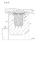
図2は、図1の部分拡大図であって、ピストン13に横荷重が作用していないときのパッキン26及びその周辺部位を示す一部省略断面図である。
FIG. 2 is a partial enlarged view of FIG. 1, and is a partially omitted cross-sectional view showing the
図2に示すように、パッキン装着溝24は、左右の側壁29aと溝底29bとで三方を囲まれた溝であり、左右の側壁29aは、ピストン13の軸線L1と直交する平坦な面であって、互いに平行しており、前記溝底29bは、ピストン13の軸線L1方向に平坦な面である。従って、このパッキン装着溝24は、全体的に均一な溝幅と均一な深さとを有するものである。また、ピストン13の外周において、パッキン装着溝24の軸線方向両側には、ピストン13の最外周面39よりも外径が小さい小径部40が、周方向に延在して設けられている。
As shown in FIG. 2, the packing mounting groove 24 is a groove surrounded on three sides by left and
パッキン26は、弾性体(例えば、ゴム材)からなるリング状のシール部材42と、このシール部材42の外周に取り付けられた2つのサポートリング44とを有する。
The packing 26 includes a ring-shaped
シール部材42は、ピストン13のパッキン装着溝24に装着されており、外周及び内周と、軸線方向両側で互いに平行な側面43とを有する。シール部材42の外周には、摺動孔18の内周面に常時接触するシール用突部46と、シール用突部46の両側に位置してパッキン装着溝24から外部に突出している2つの肩部48と、肩部48とシール用突部46との間に介在する断面U字形の凹溝50とが形成されている。
The
シール用突部46は、パッキン26の軸線方向のほぼ中央の位置に形成され、パッキン26の外周において、周方向の全周にわたって、半径方向外方に突出している。図2において仮想線で示すように、シール用突部46の最外周部は、自然状態(パッキン26に何らの圧縮荷重が作用してなく弾性変形していない状態)で、断面略円弧形状である。
The sealing
肩部48は、ピストン13の軸線L1方向に平坦な面であって、2つの肩部48の径は互いに同径である。換言すれば、ピストン13の軸線L1から一方の肩部48までの距離と他方の肩部48までの距離とは互いに等しい。ピストン13に横荷重が作用していない状態において、肩部48の外径は、シール用突部46の外径よりも小さく、ピストン13の小径部40の外径よりも大きい。
The
サポートリング44は、低摩擦材からなる。このため、サポートリング44(具体的には、サポート面52)と摺動孔18の内周面との間の摩擦係数は、シール部材42(具体的には、シール用突部46)と摺動孔18の内周面との間の摩擦係数も小さい。このような低摩擦材としては、例えば、四フッ化エチレン(PTFE)のような低摩擦性と耐摩耗性とを兼ね備えた合成樹脂材料や、金属材料等が挙げられる。
The
サポートリング44は、シール用突部46の両側に配置されている。サポートリング44の一端は、シール用突部46の側面に近接または当接し、また、サポートリング44の他端は、シール部材42の側面43よりも軸線方向に突出している。サポートリング44の外周には、ピストン13の軸線L1方向に平坦なサポート面52が設けられている。
The
サポートリング44の内周には、U字形断面をした係止用の突条54が設けられている。サポートリング44は、突条54を凹溝50に係止させることにより、シール部材42に肩部48の外周を取り巻くように取り付けられている。
A locking
シール部材42の内周には、前記パッキン装着溝24の溝底29bに弾性的に接触する断面が半円形をしたシール用の内周突起56が形成されている。この内周突起56は、シール用突部46とピストン13の軸線L1方向の同じ位置、即ち、内周の中央位置に設けられていて、シール用突部46より幅及び高さが小さい。
On the inner periphery of the
また、シール部材42の内周における内周突起56の両側には、内周突起56がパッキン装着溝24の溝底29bに押し付けられて圧縮されたとき(図4参照)、一部が溝底29bに当接する当たり面47を備えている。この当たり面47は、ピストン13が摺動孔18内に装着されていない状態においては、ピストン13の軸線L1方向に平坦な面であり、このとき内周突起56の両側にある2つの当たり面47の径は互いに等しい。
Further, on both sides of the inner
なお、内周突起56は、シール用突部46とピストン13の軸線L1方向の異なる位置に設けることもできる。
In addition, the inner
本実施形態に係る流体圧機器10は、基本的には以上のように構成されるものであり、以下、その作用及び効果について説明する。
The
図2に示すように、ピストン13に横荷重が作用していない状態において、シール用突部46は、摺動孔18の内周面に当接し、弾性圧縮変形している。この弾性圧縮変形量は、軸線周りの全周にわたって略一定である。また、サポートリング44の外周面は、軸線周りの全周にわたって摺動孔18の内周面に当接する。このとき、サポートリング44の突出端部の内周面は、ピストン13の外周に当接しない、つまり非接触である。
As shown in FIG. 2, in a state where no lateral load is applied to the
図2に示す状態で、ピストン13は摺動孔18の軸線L2方向に沿って往復移動し、これによりサポートリング44の外周面は、サポート面52と摺動孔18の内周面に対して接触しながら移動する、つまり摺動するが、サポートリング44は低摩擦材からなるため、サポート面52と摺動孔18の内周面との間の摩擦抵抗は十分に小さく、このため、ピストン13は円滑かつ安定的に動作する。
In the state shown in FIG. 2, the
図3に示すように、ピストン13に矢印A方向の小さい横荷重が作用した場合、ピストン13の軸線L1は摺動孔18の軸線L2に対して角度θだけ傾斜するが、サポートリング44の軸線は摺動孔18の軸線L2と平行を保持する。このため、サポートリング44のサポート面52と摺動孔18の内周面との接触状態は、図2の状態と同じであり、シール用突部46の弾性圧縮変形量も同じである。また、このようにピストン13に作用する横荷重が小さい場合でも、サポートリング44の外周面と摺動孔18の内周面とが面で接触するので、摺動抵抗が過大となるのが防止され、ピストン13を円滑かつ安定的に動作させることができる。
As shown in FIG. 3, when a small lateral load in the direction of arrow A acts on the
図4に示すように、ピストン13に矢印A方向の大きい横荷重が作用した場合、サポートリング44の内周面が、ピストン13の外周(図示例では、小径部40)に当接する。一方、サポートリング44のサポート面52は、ピストン13の最外周よりも半径方向外側に位置するので、ピストン13の外周は摺動孔18の内周面に接触しない。すなわち、サポートリング44により、ピストン13が摺動孔18の内周面に接触することが防止される。
As shown in FIG. 4, when a large lateral load in the direction of arrow A is applied to the
また、この状態で、サポートリング44のサポート面52と摺動孔18の内周面との接触状態は、図2及び図3の状態と同じであり、シール用突部46の弾性圧縮変形量も同じである。また、このようにピストン13に作用する横荷重が大きい場合でも、サポートリング44の外周面と摺動孔18の内周面とが面で接触するので、摺動抵抗が過大となるのが防止され、ピストン13を円滑かつ安定的に動作させることができる。
Further, in this state, the contact state between the
上述したように、本実施形態に係る流体圧機器10によれば、ピストン13に横荷重が作用したときには、サポートリング44の内周の一部とピストン13の外周の一部とが接触し、ピストン13の横方向の移動が規制されることにより、シール部材42のシール用突起が潰れすぎることが防止されるとともに、ピストン13が摺動孔18の内周面に接触することが防止される。このように、サポートリング44が従来のウエアリングと少なくとも同等の機能を担っているので、ピストン13の軸線L1方向に間隔を置いた位置にパッキン26とは別のウエアリングを配置する必要がない。このため、構成が簡単であり、また、ピストン13の軸線L1方向の寸法の増大を抑制できる。
As described above, according to the
また、上記の構成によれば、サポートリング44の内周には、内周に係止用の突条54が形成され、突条54が凹溝50に係止されることにより、サポートリング44がシール部材42に肩部48の外周を取り巻くように取り付けられるので、シール部材42へのサポートリング44の組み付けが容易になる。
Further, according to the above-described configuration, the
さらに、上記の構成によれば、サポートリング44は、ピストン13に横荷重が作用しているときもしていないときも、常時、摺動孔18の内周面に接触し、シール用突部46の弾性変形量は各状態で同じである。従って、シール用突部46と摺動孔18との接触面圧及び接触面積は、ピストン13に横荷重が作用しているときもしていないときも同じであり、ピストン13の摺動抵抗の管理が容易である。
Furthermore, according to the above-described configuration, the
またさらに、シール部材42の内周には、パッキン装着溝24の溝底29bに弾性的に接触するシール用の内周突起56が形成されているので、シール部材42の内周とパッキン装着溝24の溝低との間のシールがなされ、両者間の流体の流れが有効に阻止される。
Furthermore, since an inner
図5は、第1変形例に係るパッキン26a及びその周辺部位を示す一部省略断面図である。上述した本実施形態では、シール部材42の外周の凹溝50とサポートリング44の内周の突条54とが何れも断面U字形に形成されているが、この凹溝50と突条54とはその他の形状に形成することもできる。例えば、図5に示すシール部材42aとサポートリング44aのように、凹溝50aの肩部48a側の溝面と突条54aの該溝面に対応する側面とを、シール部材42aの軸線と直交する方向の平坦面とすることもできる。パッキン26aに関して上述した部分以外の構成については、図2に示したパッキン26と同一構成である。
FIG. 5 is a partially omitted cross-sectional view showing the
第1変形例の構成によれば、サポートリング44aをシール部材42aに対して確実に係止させることができる。あるいは、凹溝50aの左右の溝面を互いに平行な平坦面に形成するとともに底面を平坦面とし、突条54aの断面形状をこの凹溝50aの溝形状と同様な形状に形成することもできる。
According to the structure of the 1st modification, the
また、図6に示す第2変形例に係るパッキン26bのように、サポートリング44bに周方向に間隔をおいて複数の孔60を形成することもできる。図示例では、各孔60は、等間隔に配置されている。この孔60は、サポートリング44を厚さ方向に貫通している。このような孔60に代えて、サポートリング44の外周面に周方向に間隔をおいて凹部を設けてもよい。このような凹部は、サポートリング44bを厚さ方向に貫通しない穴(窪み)である。
Further, like the
このような孔60または凹部は、グリス溜の機能を持つので、その内部にグリスを保持することによってサポート面52aと摺動孔18の内面との間の良好な摺動性を長期間維持できる。
Since such a
なお、上述した実施形態では、流体圧機器10の一例として流体圧シリンダ10Aを示したが、この流体圧機器10は、ハウジング12に形成された摺動孔18内を摺動するスプールで流体流路を切り換える流体切換弁であってもよい。この場合、前記スプールが仕切部材を形成することになる。
In the above-described embodiment, the
上述した実施形態、第1変形例及び第2変形例では、サポートリング44(44a、44b)は、シール用突部46の両側に設けられた場合を説明したが、シール用突部46の片側のみに配設されてもよく、この場合、肩部48はサポートリング44が配設される側のみに設けられればよい。
In the above-described embodiment, the first modified example, and the second modified example, the support ring 44 (44a, 44b) has been described as being provided on both sides of the sealing
上記において、本発明について好適な実施の形態を挙げて説明したが、本発明は前記実施の形態に限定されるものではなく、本発明の要旨を逸脱しない範囲において、種々の改変が可能なことは言うまでもない。 In the above description, the present invention has been described with reference to preferred embodiments. However, the present invention is not limited to the above-described embodiments, and various modifications can be made without departing from the scope of the present invention. Needless to say.
10…流体圧機器 12…ハウジング
13…ピストン 24…パッキン装着溝
26、26a、26b…パッキン 42、42a…シール部材
44、44a、44b…サポートリング 46…シール用突部
48…肩部 50、50a…凹溝
52、52a…サポート面 54、54a…突条
56…内周突起
DESCRIPTION OF
Claims (4)
前記摺動孔内を軸線方向に移動する仕切部材と、
前記仕切部材の外周に装着されたパッキンと、を備え、
前記パッキンは、前記仕切部材の外周に形成された環状のパッキン装着溝に装着された、弾性材からなるリング状のシール部材と、前記シール部材の外周に取り付けられた低摩擦材からなるサポートリングと、を有し、
前記シール部材は、前記摺動孔の内周面に接触するシール用突部と、該シール用突部の両側又は片側のみに形成されて前記パッキン装着溝から外部に突出している肩部と、を外周に有し、
前記サポートリングは、前記シール用突部の両側又は片側のみに配置され、前記シール部材よりも軸線方向に突出し、
前記サポートリングの外周には、前記仕切部材の軸線方向に平坦なサポート面が形成され、
前記仕切部材に横荷重が作用していないとき、前記シール用突部は前記摺動孔の内周面に押圧されて弾性圧縮変形し、前記サポートリングの前記サポート面は前記摺動孔の内周面に接触する一方、前記サポートリングの内周面は前記仕切部材の外周に非接触の状態で前記仕切部材の外周に対向し、
前記仕切部材に所定以上の横荷重が作用しているとき、前記シール用突部は前記摺動孔の内周面に押圧されて弾性圧縮変形し、前記サポートリングの前記サポート面は前記摺動孔の内周面に接触するとともに、前記サポートリングの内周面は前記仕切部材の外周に接触する、
ことを特徴とする流体圧機器。 A housing in which a sliding hole is formed;
A partition member that moves in the axial direction in the sliding hole;
A packing mounted on the outer periphery of the partition member,
The packing is a ring-shaped seal member made of an elastic material, which is attached to an annular packing attachment groove formed on the outer periphery of the partition member, and a support ring made of a low friction material attached to the outer periphery of the seal member. And having
The seal member includes a sealing protrusion that contacts the inner peripheral surface of the sliding hole, a shoulder that is formed only on both sides or one side of the sealing protrusion and protrudes outward from the packing mounting groove, On the outer periphery,
The support ring is disposed only on both sides or one side of the seal projection, and protrudes in the axial direction from the seal member,
On the outer periphery of the support ring, a flat support surface is formed in the axial direction of the partition member,
When a lateral load is not applied to the partition member, the sealing projection is pressed against the inner peripheral surface of the sliding hole to be elastically compressed and deformed, and the support surface of the support ring is an inner portion of the sliding hole. While contacting the peripheral surface, the inner peripheral surface of the support ring faces the outer periphery of the partition member in a non-contact state with the outer periphery of the partition member ,
When a predetermined lateral load or more is applied to the partition member, the sealing protrusion is pressed against the inner peripheral surface of the sliding hole to be elastically compressed and deformed, and the support surface of the support ring is slid. While contacting the inner peripheral surface of the hole, the inner peripheral surface of the support ring contacts the outer periphery of the partition member,
Fluid pressure equipment characterized by that.
前記シール部材の外周には、前記肩部と前記シール用突部との間に介在する凹溝が設けられ、
前記サポートリングの内周には、係止用の突条が形成され、
前記突条が前記凹溝に係止されることにより、前記サポートリングが前記シール部材に前記肩部の外周を取り巻くように取り付けられる、
ことを特徴とする流体圧機器。 The fluid pressure device according to claim 1,
On the outer periphery of the seal member, a concave groove is provided to be interposed between the shoulder portion and the seal projection,
A locking ridge is formed on the inner periphery of the support ring,
The support ring is attached to the seal member so as to surround the outer periphery of the shoulder by locking the protrusion to the concave groove.
Fluid pressure equipment characterized by that.
前記シール用突部の弾性圧縮変形量は、前記仕切部材に横荷重が作用していないときと、前記仕切部材に横荷重が作用しているときとで同じである、
ことを特徴とする流体圧機器。 The fluid pressure device according to claim 1 or 2,
The amount of elastic compressive deformation of the seal projection is the same when a lateral load is not applied to the partition member and when a lateral load is applied to the partition member.
Fluid pressure equipment characterized by that.
前記シール部材の内周に、前記パッキン装着溝の溝底に弾性的に接触するシール用の内周突起が形成されている、
ことを特徴とする流体圧機器。 In the fluid pressure apparatus according to any one of claims 1 to 3,
On the inner periphery of the seal member, an inner peripheral protrusion for sealing that elastically contacts the groove bottom of the packing mounting groove is formed.
Fluid pressure equipment characterized by that.
Priority Applications (6)
| Application Number | Priority Date | Filing Date | Title |
|---|---|---|---|
| JP2010115074A JP5621091B2 (en) | 2010-05-19 | 2010-05-19 | Fluid pressure equipment |
| US13/107,230 US8739684B2 (en) | 2010-05-19 | 2011-05-13 | Fluid pressure apparatus |
| TW100116803A TWI526641B (en) | 2010-05-19 | 2011-05-13 | Fluid pressure apparatus |
| KR1020110046488A KR101802901B1 (en) | 2010-05-19 | 2011-05-17 | Fluid pressure apparatus |
| DE102011101968.9A DE102011101968B4 (en) | 2010-05-19 | 2011-05-18 | fluid pressure device |
| CN201110145285.4A CN102252093B (en) | 2010-05-19 | 2011-05-19 | Fluid pressure apparatus |
Applications Claiming Priority (1)
| Application Number | Priority Date | Filing Date | Title |
|---|---|---|---|
| JP2010115074A JP5621091B2 (en) | 2010-05-19 | 2010-05-19 | Fluid pressure equipment |
Publications (2)
| Publication Number | Publication Date |
|---|---|
| JP2011241912A JP2011241912A (en) | 2011-12-01 |
| JP5621091B2 true JP5621091B2 (en) | 2014-11-05 |
Family
ID=44971346
Family Applications (1)
| Application Number | Title | Priority Date | Filing Date |
|---|---|---|---|
| JP2010115074A Active JP5621091B2 (en) | 2010-05-19 | 2010-05-19 | Fluid pressure equipment |
Country Status (6)
| Country | Link |
|---|---|
| US (1) | US8739684B2 (en) |
| JP (1) | JP5621091B2 (en) |
| KR (1) | KR101802901B1 (en) |
| CN (1) | CN102252093B (en) |
| DE (1) | DE102011101968B4 (en) |
| TW (1) | TWI526641B (en) |
Families Citing this family (15)
| Publication number | Priority date | Publication date | Assignee | Title |
|---|---|---|---|---|
| JP5621091B2 (en) | 2010-05-19 | 2014-11-05 | Smc株式会社 | Fluid pressure equipment |
| JP5636613B2 (en) * | 2010-05-19 | 2014-12-10 | Smc株式会社 | Fluid pressure equipment |
| JP5621092B2 (en) | 2010-05-19 | 2014-11-05 | Smc株式会社 | Fluid pressure equipment |
| CN102705295A (en) * | 2012-05-30 | 2012-10-03 | 马鞍山市裕华机械制造有限公司 | Guide sleeve of hydraulic oil cylinder |
| US10316604B2 (en) * | 2014-07-02 | 2019-06-11 | Utex Industries, Inc. | Inflatable seal with fabric expansion restriction |
| CN104154072A (en) * | 2014-07-30 | 2014-11-19 | 莱歇研磨机械制造(上海)有限公司 | Improved structure of hydraulic cylinder of hydraulic loading system for mill |
| US10041325B2 (en) * | 2014-08-01 | 2018-08-07 | Utex Industries, Inc. | High pressure seal with composite anti-extrusion mechanism |
| JP6097799B2 (en) * | 2015-08-25 | 2017-03-15 | Kyb株式会社 | Fluid pressure cylinder |
| JP6647551B2 (en) * | 2015-10-14 | 2020-02-14 | Smc株式会社 | Fluid pressure device and manufacturing method thereof |
| CN108087548B (en) * | 2017-11-07 | 2022-03-15 | 广东盛路通信有限公司 | Sealing structure and method for matching surfaces of multiple parts |
| DE102017220691A1 (en) * | 2017-11-20 | 2019-05-23 | Bayerische Motoren Werke Aktiengesellschaft | Arrangement structure and method for producing a component arrangement |
| CN111212995B (en) * | 2018-05-30 | 2022-01-11 | Nok株式会社 | Sealing ring and sealing structure |
| US11242933B2 (en) * | 2019-06-03 | 2022-02-08 | Fisher Controls International Llc | Floating valve seat for a rotary control valve for use in severe service applications |
| JP2021004670A (en) * | 2019-06-27 | 2021-01-14 | 株式会社デンソー | Valve device |
| JP2022050742A (en) * | 2020-09-18 | 2022-03-31 | トヨタ自動車株式会社 | Plunger tip and sliding method |
Family Cites Families (46)
| Publication number | Priority date | Publication date | Assignee | Title |
|---|---|---|---|---|
| US2349170A (en) | 1942-01-23 | 1944-05-16 | Woodling George V | Sealing device |
| US2765204A (en) | 1954-11-05 | 1956-10-02 | Greene Tweed & Co Inc | Sealing device |
| GB1160574A (en) * | 1966-08-05 | 1969-08-06 | Dowty Seals Ltd | Seal |
| DE6811760U (en) | 1968-12-17 | 1969-04-17 | Carl Freudenberg | PISTON SEAL |
| DE1948432A1 (en) | 1969-09-25 | 1971-05-19 | Merkel Asbest & Gummiwerke | Rubber-elastic, fabric-reinforced sealing ring for an undivided piston |
| US3582094A (en) * | 1970-02-16 | 1971-06-01 | Greene Tweed & Co Inc | Sealing assembly |
| GB1316841A (en) | 1970-03-31 | 1973-05-16 | Hallite Holdings Ltd | Piston seal assembly |
| US3771801A (en) | 1972-06-05 | 1973-11-13 | Greene Tweed & Co Inc | Sealing device |
| FR2231267A5 (en) * | 1973-05-21 | 1974-12-20 | Dechavanne Jacques | |
| DE7417490U (en) | 1973-05-21 | 1974-09-12 | Dechavanne J | Piston seal |
| US4059280A (en) | 1975-07-02 | 1977-11-22 | Hall & Hall Limited | Seal ring assembly |
| CH599487A5 (en) * | 1976-11-23 | 1978-05-31 | Patent & Inventions Ltd | |
| GB1512181A (en) | 1977-01-06 | 1978-05-24 | Polypac Ltd | Packing assemblies |
| US4177837A (en) * | 1977-05-19 | 1979-12-11 | Abex Corporation | Accumulator |
| JPS5919161Y2 (en) * | 1979-11-02 | 1984-06-02 | 帝国ピストンリング株式会社 | combination seal ring |
| US4305595A (en) * | 1980-04-30 | 1981-12-15 | Hydril Company | Composite seal |
| GB2077368A (en) | 1980-06-05 | 1981-12-16 | Weir Polypac Ltd | Packing assembly |
| AT368406B (en) | 1980-09-18 | 1982-10-11 | Raedler Xaver S | PIPE CLEANING DEVICE |
| US4484512A (en) * | 1981-09-10 | 1984-11-27 | Jacques Dechavanne | Seal, scraper, and guide for double-acting piston |
| US4577874A (en) | 1983-06-13 | 1986-03-25 | Microdot Incorporated | Seal assembly |
| JPS60121560A (en) | 1983-12-02 | 1985-06-29 | Matsushita Electric Ind Co Ltd | Magnetic recording and reproducing device |
| EP0147764B1 (en) | 1983-12-16 | 1988-06-15 | C.I. Kasei Co., Ltd | Joint sealing member |
| JPS60121560U (en) * | 1983-12-22 | 1985-08-16 | 三菱電線工業株式会社 | Sliding packing |
| JPS6132862A (en) | 1984-07-25 | 1986-02-15 | Fuji Xerox Co Ltd | Managing device of copying machine |
| JPS6132862U (en) * | 1984-07-31 | 1986-02-27 | 三菱電線工業株式会社 | sealing device |
| US4576386A (en) | 1985-01-16 | 1986-03-18 | W. S. Shamban & Company | Anti-extrusion back-up ring assembly |
| DE3533797A1 (en) | 1985-09-21 | 1987-04-02 | Walter Hunger | SEALING DEVICE |
| DK157947C (en) | 1987-03-20 | 1990-09-10 | Shamban W S Europ | COMBINATION SEAL FOR SEAL BETWEEN TWO MACHINE ELEMENTS |
| US5014603A (en) | 1989-11-02 | 1991-05-14 | Allied-Signal Inc. | Hydraulic actuator having frangible or deformable components |
| JP2574206Y2 (en) * | 1991-09-30 | 1998-06-11 | いすゞ自動車株式会社 | Piston device |
| US5385081A (en) * | 1993-09-09 | 1995-01-31 | Arde Incorporated | Fluid storage tank employing a shear seal |
| US5524905A (en) | 1994-09-28 | 1996-06-11 | Greene, Tweed Of Delaware, Inc. | Sealing assembly with T-shaped seal ring and anti-extrusion rings |
| JPH08326914A (en) | 1995-03-31 | 1996-12-10 | Ntn Corp | Piston of hot gas machine |
| JPH0972310A (en) | 1995-09-01 | 1997-03-18 | Nok Corp | Sealing device for piston |
| JP3471498B2 (en) | 1995-09-25 | 2003-12-02 | Nok株式会社 | Packing |
| US5879010A (en) | 1997-07-22 | 1999-03-09 | Green Tweed Of Delaware, Inc. | Seal assembly with mechanically joined anti-extrusion rings |
| US6173964B1 (en) | 1998-07-07 | 2001-01-16 | Greene, Tweed Of Delaware, Inc. | Seal assembly with backup elements having coil springs positioned therein |
| JP2000074009A (en) | 1998-08-31 | 2000-03-07 | Mitsubishi Plastics Ind Ltd | Heat resisting air cylinder |
| US6217030B1 (en) | 1999-02-09 | 2001-04-17 | Richard D. Zitting | Seal assembly |
| DE10117662C1 (en) * | 2001-04-09 | 2003-01-16 | Freudenberg Carl Kg | Rod or piston primary seal |
| JP2003120602A (en) | 2001-10-12 | 2003-04-23 | Nok Corp | Piston type accumulator |
| US7568424B2 (en) * | 2002-01-02 | 2009-08-04 | Flow International Corporation | Method and apparatus for sealing an ultrahigh-pressure fluid system |
| US8246055B2 (en) | 2008-02-29 | 2012-08-21 | Zodiac Pool Systems, Inc. | Multi-lobed seal member |
| JP5304057B2 (en) * | 2008-07-02 | 2013-10-02 | Nok株式会社 | Sealing device and sealing structure |
| WO2010018640A1 (en) | 2008-08-15 | 2010-02-18 | 日本バルカー工業株式会社 | Piston sealant |
| JP5621091B2 (en) | 2010-05-19 | 2014-11-05 | Smc株式会社 | Fluid pressure equipment |
-
2010
- 2010-05-19 JP JP2010115074A patent/JP5621091B2/en active Active
-
2011
- 2011-05-13 TW TW100116803A patent/TWI526641B/en not_active IP Right Cessation
- 2011-05-13 US US13/107,230 patent/US8739684B2/en active Active
- 2011-05-17 KR KR1020110046488A patent/KR101802901B1/en active IP Right Grant
- 2011-05-18 DE DE102011101968.9A patent/DE102011101968B4/en not_active Expired - Fee Related
- 2011-05-19 CN CN201110145285.4A patent/CN102252093B/en not_active Expired - Fee Related
Also Published As
| Publication number | Publication date |
|---|---|
| JP2011241912A (en) | 2011-12-01 |
| CN102252093A (en) | 2011-11-23 |
| TWI526641B (en) | 2016-03-21 |
| DE102011101968B4 (en) | 2022-07-14 |
| KR101802901B1 (en) | 2017-11-29 |
| US8739684B2 (en) | 2014-06-03 |
| DE102011101968A1 (en) | 2012-02-09 |
| TW201202577A (en) | 2012-01-16 |
| KR20110127608A (en) | 2011-11-25 |
| CN102252093B (en) | 2015-07-01 |
| US20110283880A1 (en) | 2011-11-24 |
Similar Documents
| Publication | Publication Date | Title |
|---|---|---|
| JP5621091B2 (en) | Fluid pressure equipment | |
| JP5621092B2 (en) | Fluid pressure equipment | |
| JP5636613B2 (en) | Fluid pressure equipment | |
| US9512924B2 (en) | Sealing structure | |
| US20100295253A1 (en) | Packing and sealing system | |
| KR20130031350A (en) | Piston bearing structure for fluid pressure cylinder | |
| CN108779859B (en) | Sealing structure | |
| WO2013172094A1 (en) | Buffer ring | |
| JP2012002325A (en) | Fluid pressure apparatus | |
| JP2017015245A (en) | Fluid pressure cylinder | |
| US11221072B2 (en) | Arrangement structure for seal member | |
| JP5177391B2 (en) | Piston seal structure | |
| JP6076789B2 (en) | Seal structure | |
| JP7262764B2 (en) | Ball valve | |
| WO2018056216A1 (en) | Shock absorber | |
| JP2008121846A (en) | Backup ring | |
| JP2012137121A (en) | Sealing device | |
| JP2006250245A (en) | Piston ring | |
| CN112013112A (en) | Sealing ring | |
| JP2012229759A (en) | Wear ring used in linear actuator | |
| JP2019138388A (en) | Sealing device | |
| JP2014109322A (en) | Slide seal and seal structure |
Legal Events
| Date | Code | Title | Description |
|---|---|---|---|
| A621 | Written request for application examination |
Free format text: JAPANESE INTERMEDIATE CODE: A621 Effective date: 20130416 |
|
| A977 | Report on retrieval |
Free format text: JAPANESE INTERMEDIATE CODE: A971007 Effective date: 20131227 |
|
| A131 | Notification of reasons for refusal |
Free format text: JAPANESE INTERMEDIATE CODE: A131 Effective date: 20140107 |
|
| A521 | Request for written amendment filed |
Free format text: JAPANESE INTERMEDIATE CODE: A523 Effective date: 20140306 |
|
| TRDD | Decision of grant or rejection written | ||
| A01 | Written decision to grant a patent or to grant a registration (utility model) |
Free format text: JAPANESE INTERMEDIATE CODE: A01 Effective date: 20140729 |
|
| A61 | First payment of annual fees (during grant procedure) |
Free format text: JAPANESE INTERMEDIATE CODE: A61 Effective date: 20140821 |
|
| R150 | Certificate of patent or registration of utility model |
Ref document number: 5621091 Country of ref document: JP Free format text: JAPANESE INTERMEDIATE CODE: R150 |
|
| R250 | Receipt of annual fees |
Free format text: JAPANESE INTERMEDIATE CODE: R250 |
|
| R250 | Receipt of annual fees |
Free format text: JAPANESE INTERMEDIATE CODE: R250 |
|
| R250 | Receipt of annual fees |
Free format text: JAPANESE INTERMEDIATE CODE: R250 |
|
| R250 | Receipt of annual fees |
Free format text: JAPANESE INTERMEDIATE CODE: R250 |
|
| R250 | Receipt of annual fees |
Free format text: JAPANESE INTERMEDIATE CODE: R250 |
|
| R250 | Receipt of annual fees |
Free format text: JAPANESE INTERMEDIATE CODE: R250 |
|
| R250 | Receipt of annual fees |
Free format text: JAPANESE INTERMEDIATE CODE: R250 |