JP5619084B2 - Synchronous motor - Google Patents
Synchronous motor Download PDFInfo
- Publication number
- JP5619084B2 JP5619084B2 JP2012159826A JP2012159826A JP5619084B2 JP 5619084 B2 JP5619084 B2 JP 5619084B2 JP 2012159826 A JP2012159826 A JP 2012159826A JP 2012159826 A JP2012159826 A JP 2012159826A JP 5619084 B2 JP5619084 B2 JP 5619084B2
- Authority
- JP
- Japan
- Prior art keywords
- teeth
- rotor
- synchronous motor
- winding
- stator
- Prior art date
- Legal status (The legal status is an assumption and is not a legal conclusion. Google has not performed a legal analysis and makes no representation as to the accuracy of the status listed.)
- Expired - Fee Related
Links
Images


Classifications
-
- H—ELECTRICITY
- H02—GENERATION; CONVERSION OR DISTRIBUTION OF ELECTRIC POWER
- H02K—DYNAMO-ELECTRIC MACHINES
- H02K21/00—Synchronous motors having permanent magnets; Synchronous generators having permanent magnets
- H02K21/12—Synchronous motors having permanent magnets; Synchronous generators having permanent magnets with stationary armatures and rotating magnets
- H02K21/14—Synchronous motors having permanent magnets; Synchronous generators having permanent magnets with stationary armatures and rotating magnets with magnets rotating within the armatures
-
- H—ELECTRICITY
- H02—GENERATION; CONVERSION OR DISTRIBUTION OF ELECTRIC POWER
- H02K—DYNAMO-ELECTRIC MACHINES
- H02K21/00—Synchronous motors having permanent magnets; Synchronous generators having permanent magnets
- H02K21/12—Synchronous motors having permanent magnets; Synchronous generators having permanent magnets with stationary armatures and rotating magnets
- H02K21/22—Synchronous motors having permanent magnets; Synchronous generators having permanent magnets with stationary armatures and rotating magnets with magnets rotating around the armatures, e.g. flywheel magnetos
Landscapes
- Engineering & Computer Science (AREA)
- Power Engineering (AREA)
- Permanent Magnet Type Synchronous Machine (AREA)
Description
本発明は、同期電動機に関する。 The present invention relates to a synchronous motor.
小型の送風機に用いられる電動機としては、一般に、安価で小型の単相誘導電動機が用いられることが多い。この単相誘導電動機は、効率が低いため、出力が小さい割には、消費電力が大きいという欠点がある。このような欠点を改善するものとして、一般的な固定子の巻線が異なる相同志をラップさせる分布巻き構造に対し、巻線のコイルを小さくできる集中巻き構造としたかご形3相誘導電動機があるが、回転子のかご形導体に電流を発生させるためのエネルギーを固定子側より供給するため、回転子から発生する磁束を永久磁石から供給する同期電動機に比べると効率が低く、消費電力の削減にも限界がある。 In general, an inexpensive and small single-phase induction motor is often used as a motor used for a small blower. Since this single-phase induction motor has low efficiency, there is a drawback that power consumption is large for a small output. In order to remedy such drawbacks, there is a squirrel-cage three-phase induction motor having a concentrated winding structure that can reduce the winding coil, in contrast to a distributed winding structure in which common stator windings wrap different homologs. However, since the energy for generating current to the cage conductor of the rotor is supplied from the stator side, the efficiency is lower than the synchronous motor that supplies the magnetic flux generated from the rotor from the permanent magnet, and the power consumption is low. There are limits to reduction.
一方、OA機器や設備の冷却用に用いられる、所謂「軸流ファン」の電動機としては、単相同期電動機が用いられることが多い。この単相同期電動機は、集中巻き構造の固定子と、固定子のティースと同数の磁極の回転子とを組み合わせて構成され、一般に、駆動回路のコストを抑制するために半波整流後の電流を用いて駆動されるが、通電する相を切り替えるタイミングで出力トルクが大きく落ち込み、リップルが大きくなるため、振動や騒音が大きいという欠点がある。 On the other hand, a single-phase synchronous motor is often used as a so-called “axial fan” motor used for cooling OA equipment and equipment. This single-phase synchronous motor is configured by combining a stator with a concentrated winding structure and a rotor with the same number of magnetic poles as the stator teeth. Generally, the current after half-wave rectification is used to reduce the cost of the drive circuit. However, there is a drawback that the vibration and noise are large because the output torque is greatly reduced and the ripple is increased at the timing of switching the energized phase.
集中巻き構造の同期電動機において、トルクリップルを抑制して低振動化、低騒音化を図る技術としては、例えば、回転子の極数に対して固定子の突極(ティース)を少なくし、2相の巻線に90°の位相差を有する2相の交流電流を通電して駆動することで、高効率化、高トルク化を図りつつ、出力トルクの落ち込みを少なくして、低振動化、低騒音化を図るものがある(例えば、特許文献1)。 In a synchronous motor having a concentrated winding structure, as a technique for reducing torque ripple and reducing vibration and noise, for example, the number of stator salient poles (tooth) is reduced with respect to the number of rotor poles, and 2 By driving a two-phase alternating current having a phase difference of 90 ° to the winding of the phase and driving, it is possible to reduce the drop in the output torque while reducing the output torque while increasing the efficiency and torque. There is one that reduces noise (for example, Patent Document 1).
永久磁石を用いた同期電動機では、振動や騒音の別の要因として、回転子の永久磁石と固定子のティースとの間に働く磁気吸引力に起因して発生するコギングトルクがある。このコギングトルクは、回転子の機械的な1回転中にスロット数と磁極数との最小公倍数で発生するトルク脈動成分である。この回転子の1回転中に発生するコギングトルクの脈動数が多いほど、エネルギーが分散され、これに伴ってコギングトルクの振幅が小さくなり、振動や騒音が小さくなる。逆に、コギングトルクの脈動数が少ないほど、コギングトルクの振幅が大きくなり、振動や騒音が大きくなる。上記従来技術は、回転子の極数に対してティースの数を少なくする、つまりスロット数を少なくすることで、巻線を巻回するスペースを拡大して高効率化、高トルク化を図るものであるので、スロット数と磁極数との組み合わせによっては、コギングトルクの脈動数が少なくなり、これに伴ってコギングトルクの振幅が大きくなり、振動や騒音が大きくなる場合がある、という問題があった。 In a synchronous motor using a permanent magnet, another factor of vibration and noise is cogging torque generated due to a magnetic attractive force acting between the permanent magnet of the rotor and the teeth of the stator. This cogging torque is a torque pulsation component generated at the least common multiple of the number of slots and the number of magnetic poles during one mechanical rotation of the rotor. As the number of pulsations of the cogging torque generated during one rotation of the rotor increases, the energy is dispersed, and accordingly, the amplitude of the cogging torque is reduced, and vibration and noise are reduced. Conversely, the smaller the pulsation number of the cogging torque, the larger the amplitude of the cogging torque, and the greater the vibration and noise. The above prior art reduces the number of teeth with respect to the number of poles of the rotor, that is, reduces the number of slots, thereby expanding the space for winding the windings to achieve higher efficiency and higher torque. Therefore, depending on the combination of the number of slots and the number of magnetic poles, there is a problem that the number of pulsations of the cogging torque decreases, and this increases the amplitude of the cogging torque, which may increase vibration and noise. It was.
本発明は、上記に鑑みてなされたものであって、高効率化、高トルク化を図りつつ、より低振動化、低騒音化を図ることができる同期電動機を提供することを目的とする。 The present invention has been made in view of the above, and an object of the present invention is to provide a synchronous motor that can achieve lower vibration and lower noise while achieving higher efficiency and higher torque.
上述した課題を解決し、目的を達成するため、本発明にかかる同期電動機は、電気角で90°位相の異なる2相の交流電流により駆動される同期電動機であって、4n(nは自然数)個のティースが周方向に等角度間隔で形成され、前記各ティースに巻線が集中巻きで巻回された固定子と、軟磁性材料のバックヨークの表面に、6n個の永久磁石が異なる極性を交互にして周方向に等角度間隔で配置され、前記固定子に対向配置された回転子と、を備え、前記各ティースの前記回転子に対向する部分の幅は、機械角で略(45/n)°であることを特徴とする。 In order to solve the above-described problems and achieve the object, a synchronous motor according to the present invention is a synchronous motor driven by a two-phase alternating current having an electrical angle of 90 ° and a phase difference of 4n (n is a natural number). The teeth are formed at equal angular intervals in the circumferential direction, and 6n permanent magnets have different polarities on the surface of the back yoke of the soft magnetic material and the stator in which the winding is wound around each of the teeth by concentrated winding. Are arranged at equal angular intervals in the circumferential direction, and opposed to the stator, and the width of the portion of each tooth facing the rotor is substantially mechanical angle (45 / N) °.
本発明によれば、高効率化、高トルク化を図りつつ、より低振動化、低騒音化を図ることができる、という効果を奏する。 According to the present invention, there is an effect that vibration and noise can be further reduced while achieving high efficiency and high torque.
以下に添付図面を参照し、本発明の実施の形態にかかる同期電動機について説明する。なお、以下に示す実施の形態により本発明が限定されるものではない。 A synchronous motor according to an embodiment of the present invention will be described below with reference to the accompanying drawings. In addition, this invention is not limited by embodiment shown below.
実施の形態1.
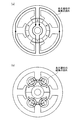
図1は、実施の形態1にかかる同期電動機の横断面図である。図1に示すように、本実施の形態では、固定子1の内周面に対向して回転子4を配置した、所謂インナーロータ型の同期電動機である場合の例について説明する。
Embodiment 1 FIG.
FIG. 1 is a cross-sectional view of the synchronous motor according to the first embodiment. As shown in FIG. 1, in the present embodiment, an example in the case of a so-called inner rotor type synchronous motor in which a rotor 4 is disposed facing the inner peripheral surface of a stator 1 will be described.
固定子1は、軸心を中心とする円環状の鉄心に4n(nは自然数)個の突起状の鉄心(以下、「ティース」という)2a,2b,2c,2dが軸心に向かって周方向に等角度間隔で形成され、この各ティース2a,2b,2c,2dに巻線が集中巻きで巻回され4n個のコイル3が形成されている。
The stator 1 has an annular iron core centered on the shaft center and 4n (n is a natural number) protruding iron cores (hereinafter referred to as “teeth”) 2a, 2b, 2c, 2d around the shaft center. The
各ティース2a,2b,2c,2dは、2n個ずつの2組に区分される。このとき、一方の組を成す各ティース(ここでは、各ティース2a,2c)と他方の組を成す各ティース(ここでは、各ティース2b,2d)とが交互に配置されるように区分される。各ティース2a,2b,2c,2dに巻回される巻線は、一方の組を成す各ティース(ここでは、各ティース2a,2c)に巻回される巻線と、他方の組を成す各ティース(ここでは、各ティース2b,2d)に巻回される巻線との2つに分離した2相の巻線としており、同じ組内において隣接する各ティース(ここでは、各ティース2a,2c、あるいは、各ティース2b,2d)に巻回する巻線の巻回方向を軸心から見て互いに逆方向としている。
Each
なお、図1に示す実線矢印は、各コイル3を形成する各巻線(A相(+)巻線、A相(−)巻線、B相(+)巻線、B相(−)巻線)に流れる正方向電流の向きを示している。この固定子1の構成は、集中巻きの誘導電動機の固定子の構成と同様である。また、各ティース2a,2b,2c,2dの回転子4に対向する部分の幅(以下、「先端幅」という)は、軸心を中心として機械角で略(45/n)°としている。
In addition, the solid line arrow shown in FIG. 1 indicates each winding (A phase (+) winding, A phase (−) winding, B phase (+) winding, B phase (−) winding) forming each
回転子4は、軸心を中心とする円柱状の軟磁性材料のバックヨーク5の外周面に、6n個の平行配向あるいはラジアル配向された永久磁石6が異なる極性を交互にして周方向に等角度間隔で配置され、各ティース2a,2b,2c,2dの内側に固定子1に対向して回転可能に配置されている。
The rotor 4 has 6n parallel or radial-oriented
なお、図1に示す例では、n=1、つまり、固定子1の突極数(ティース数)が4、回転子4の極数が6、各ティース2a,2b,2c,2dの先端幅が軸心を中心として機械角で略45°である例を示している。また、以下の説明において、各ティース2a,2b,2c,2dを特に区別する必要のない場合には、ティース2と称する。
In the example shown in FIG. 1, n = 1, that is, the number of salient poles (teeth number) of the stator 1 is 4, the number of poles of the rotor 4 is 6, and the tip widths of the
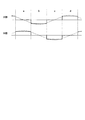
つぎに、実施の形態1にかかる同期電動機の動作について、図2および図3を参照して説明する。図2は、実施の形態1にかかる同期電動機の駆動電流の一例を示す図である。また、図3は、図2に示す駆動電流の各状態において各コイルに流れる電流方向を示す図である。 Next, the operation of the synchronous motor according to the first embodiment will be described with reference to FIGS. FIG. 2 is a diagram illustrating an example of a drive current of the synchronous motor according to the first embodiment. FIG. 3 is a diagram showing the direction of current flowing through each coil in each state of the drive current shown in FIG.
図2に示すように、本実施の形態にかかる同期電動機では、電気角で90°位相の異なる2相(A相、B相)の交流電流(図2中において一点鎖線で示す)により駆動されるが、ここでは、説明を容易とするため、90°ずつ位相を区切った矩形波電流(図2中において実線で示す)を与える例について説明する。また、ここでは、B相巻線に正方向に電流を通電した状態を状態a、A相巻線に負方向に電流を通電した状態を状態b、B相巻線に負方向に電流を通電した状態を状態c、A相巻線に正方向に電流を通電した状態を状態dとする。 As shown in FIG. 2, the synchronous motor according to the present embodiment is driven by two-phase (A-phase and B-phase) alternating currents (indicated by a one-dot chain line in FIG. 2) whose electrical angles are 90 ° different in phase. However, here, for ease of explanation, an example in which a rectangular wave current (indicated by a solid line in FIG. 2) in which phases are divided by 90 ° will be described. Also, here, a state where the B-phase winding is energized in the positive direction is a state a, a state where the A-phase winding is energized in the negative direction is a state b, and a B-phase winding is energized in the negative direction. This state is referred to as state c, and the state in which a current is passed through the A-phase winding in the positive direction is referred to as state d.
状態aでは、B相(+)巻線を巻回したティース2bにN極の磁極が発生し、B相(−)巻線を巻回したティース2dにS極の磁極が発生する。ここで、図3(a)に示すように、各ティース2b,2dに対向する回転子4の表面にN極およびS極の両方の磁極が存在する場合、各ティース2b,2dに発生した磁極との吸引、反発によって、回転子4は時計回り(図3(a)中に破線矢印で示す)に回転する。
In state a, an N-pole magnetic pole is generated in the
ティース2bに発生したN極の磁極と回転子4のS極の磁極、および、ティース2dに発生したS極の磁極と回転子4のN極の磁極とが対向する角度まで回転子4が回転すると、図3(b)に示すように、A相(+)巻線を巻回したティース2aおよびA相(−)巻線を巻回したティース2cには、回転子4のN極およびS極の両方の磁極が対向する。このタイミングで状態bに移行、つまり、A相巻線に負方向に電流を通電すると、A相(+)巻線を巻回したティース2aにS極の磁極が発生し、A相(−)巻線を巻回したティース2cにN極の磁極が発生し、回転子4の各磁極との吸引、反発によって、回転子4は時計回り(図3(b)中に破線矢印で示す)に回転する。
The rotor 4 rotates to an angle at which the N-pole magnetic pole generated in the
ティース2aに発生したS極の磁極と回転子4のN極の磁極、および、ティース2cに発生したN極の磁極と回転子4のS極の磁極とが対向する角度まで回転子4が回転すると、図3(c)に示すように、B相(+)巻線を巻回したティース2bおよびB相(−)巻線を巻回したティース2dには、回転子4のN極およびS極の両方の磁極が対向する。このタイミングで状態cに移行、つまり、B相巻線に負方向に電流を通電すると、B相(+)巻線を巻回したティース2bにS極の磁極が発生し、B相(−)巻線を巻回したティース2dにN極の磁極が発生し、回転子4の各磁極との吸引、反発によって、回転子4は時計回り(図3(c)中に破線矢印で示す)に回転する。
The rotor 4 rotates to an angle at which the S-pole magnetic pole generated on the
ティース2bに発生したS極の磁極と回転子4のN極の磁極、および、ティース2dに発生したN極の磁極と回転子4のS極の磁極とが対向する角度まで回転子4が回転すると、図3(d)に示すように、A相(+)巻線を巻回したティース2aおよびA相(−)巻線を巻回したティース2cには、回転子4のN極およびS極の両方の磁極が対向する。このタイミングで状態dに移行、つまり、A相巻線に正方向に電流を通電すると、A相(+)巻線を巻回したティース2aにN極の磁極が発生し、A相(−)巻線を巻回したティース2cにS極の磁極が発生し、回転子4の各磁極との吸引、反発によって、回転子4は時計回り(図3(d)中に破線矢印で示す)に回転する。
The rotor 4 rotates to an angle at which the S-pole magnetic pole generated in the
以降、上述した状態a〜状態dを繰り返すことにより、回転子4の回転が持続される。 Thereafter, the rotation of the rotor 4 is continued by repeating the above-described states a to d.
一般に、軸流ファン等に用いられる単相同期電動機では、ティースの数と磁極の数を一致させることが多く、この場合は、ティースと回転子の磁極の位置によっては、どの巻線に通電しても回転子が回転できない位置や、どちらの方向に回転するか特定できない位置が存在する。 In general, in a single-phase synchronous motor used for an axial fan or the like, the number of teeth and the number of magnetic poles are often matched. In this case, depending on the position of the magnetic poles of the teeth and the rotor, which winding is energized However, there are positions where the rotor cannot rotate and positions where it cannot be specified in which direction.
これに対し、本実施の形態にかかる同期電動機では、固定子1のティース2の数と回転子4の磁極数とが異なっているため、回転子4の磁極位置を把握していれば、確実に回転方向を特定して電動機を駆動することができる。また、2相の巻線に通電される電流は、90°位相がずれているため、同時に0となるタイミングは不要である。このため、トルクが大きく落ち込むことを抑えることができ、振動、騒音を抑えることができる。
On the other hand, in the synchronous motor according to this embodiment, the number of
つぎに、永久磁石を用いた同期電動機で発生するコギングトルクについて説明する。上述したように、永久磁石を用いた同期電動機では、その原理上、スロット数と磁極数との最小公倍数の脈動数のコギングトルクが発生する。図1に示すように、固定子1のティース数が4、つまり、スロット数が4であり、回転子4の極数が6(4スロット6極)である場合には、回転子4の1回転中に12回の脈動、つまりコギングトルクが発生する。このコギングトルクの数が多いほど、これに伴ってコギングトルクの振幅が小さくなり、振動や騒音が小さくなる。
Next, cogging torque generated in a synchronous motor using a permanent magnet will be described. As described above, in a synchronous motor using a permanent magnet, a cogging torque having a pulsation number of the least common multiple of the number of slots and the number of magnetic poles is generated in principle. As shown in FIG. 1, when the number of teeth of the stator 1 is 4, that is, the number of slots is 4, and the number of poles of the rotor 4 is 6 (4
一般に、ティースに発生する磁極と回転子の磁極との位置関係において、磁気回路上、安定しやすい位置と不安点になる位置とが存在し、コギングトルクは、不安定な状態から安定な状態へと回転子が移動しようとする力として発生する。脈動数が小さいということは、複数ある磁気回路上安定する位置が少ないということとなり、安定する位置間の距離が大きくなる。安定する位置間の距離が大きいほど、不安定な位置から安定する位置へ回転しようとする力が大きくなるため、脈動数が小さいと、コギングトルクの振幅は大きくなる。 Generally, in the positional relationship between the magnetic poles generated in the teeth and the magnetic poles of the rotor, there are positions on the magnetic circuit that are likely to be stable and positions that become uneasy. Cogging torque changes from an unstable state to a stable state. And generated as a force that the rotor tries to move. A small number of pulsations means that there are few stable positions on a plurality of magnetic circuits, and the distance between stable positions is large. The greater the distance between the stable positions, the greater the force to rotate from the unstable position to the stable position. Therefore, when the pulsation number is small, the amplitude of the cogging torque increases.
また、ティース間の鉄心が存在しない領域(スロットオープニング)が大きくなると、回転子表面の磁気回路のアンバランスが大きくなるため、コギングトルクは大きくなる。 Further, when the region where the iron core between the teeth does not exist (slot opening) becomes large, the unbalance of the magnetic circuit on the rotor surface becomes large, so that the cogging torque becomes large.
本実施の形態では、ティース2の回転子4に対向する先端幅を、機械角で略(45/n)°とすることにより、コギングトルクの低減を図るものである。以下、この技術的根拠について、図4〜図6を参照して説明する。
In this embodiment, the cogging torque is reduced by setting the tip width of the
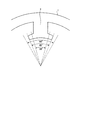
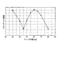
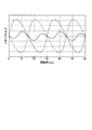
図4は、図1に示す同期電動機のティースの先端部の拡大図である。また、図5は、図1に示す同期電動機のティースの先端幅をパラメータとして、コギングトルクの振幅を比較した図である。また、図6は、ティースの先端幅が60°、45°、30°である場合における回転子の回転角とコギングトルクとの関係を示す図である。 FIG. 4 is an enlarged view of the distal end portion of the teeth of the synchronous motor shown in FIG. FIG. 5 is a diagram comparing the amplitude of cogging torque using the tip width of the teeth of the synchronous motor shown in FIG. 1 as a parameter. FIG. 6 is a diagram showing the relationship between the rotation angle of the rotor and the cogging torque when the tip width of the teeth is 60 °, 45 °, and 30 °.
ティース2の先端幅が90°の場合には、隣り合うティースが接することとなり、スロットオープニングは0となる。図5に示すように、ティース2の先端幅が60°のときは、コギングトルクの振幅は極大値をとり、ティース2の先端幅が45°のとき、コギングトルクの振幅は小さくなる。また、ティース2の先端幅が30°のとき、コギングトルクの振幅は大きくなる。
When the tip width of the
ティース2の先端幅が60°のとき、ティース2の先端幅と、回転子4の磁極の幅とが一致する。このため、回転子4の磁極とティース2が対向した位置、磁極間とティース2の中央の位置が一致した位置で、磁気回路上、非常に安定するため、コギングトルクの振幅は大きくなる(図6において一点鎖線で示す線)。
When the tip width of the
ティース2の先端幅が30°のとき、スロットオープニングの幅が60°となり、回転子4の磁極の幅と一致する。このため、ティース2の先端幅が60°のときとは逆位相の振幅の大きなコギングトルクが発生する(図6において破線で示す線)。
When the tip width of the
一方、ティース2の先端幅が45°のときには、ティース2の先端幅が60°の場合のコギングトルクとティース2の先端幅が30°の場合のコギングトルクとが互いに打ち消し合うこととなり、コギングトルクの振幅は小さくなる(図6において実線で示す線)。また、図6に示すように、コギングトルクの脈動数は、ティース2の先端幅が60°、30°の場合の2倍となっている。これは、別の観点では、スロット数が8である場合の脈動数(8スロット6極である場合の8と6との最小公倍数24)と等しくなるため、コギングトルクの振幅が小さくなっているとも言える。
On the other hand, when the tip width of the
なお、図5に示すように、ティースの先端幅を60°よりも大きく、つまり、スロットオープニングの幅を30°より小さくしてもコギングトルクの振幅を小さくすることができるが、スロットオープニングの幅が小さいと、回転子から発生する磁束が、ティースの先端部から隣のティースの先端部を通って回転子へ戻る経路を通過しやすくなるため、固定子の巻線へ磁束の鎖交量が減少して、電動機の出力トルクが低下する。 As shown in FIG. 5, the amplitude of the cogging torque can be reduced even if the tip width of the teeth is larger than 60 °, that is, the slot opening width is smaller than 30 °. Is small, it is easy for the magnetic flux generated from the rotor to pass through the path from the tip of the tooth to the rotor through the tip of the adjacent tooth. As a result, the output torque of the motor decreases.
また、ティースの先端部は、回転子の永久磁石に近いため、磁束が集中しやすく、回転子の回転に応じた磁束密度の変化も大きいため、鉄損が発生しやすい。同期電動機の場合、鉄損の発生が大きいと、この鉄損が電動機自体にブレーキとして作用するため、電動機の効率が悪化する。特に小型で出力の小さい電動機では、この影響が大きい。このため、ティースの先端幅は、巻線に鎖交する磁束が大きく低下しない程度に狭くすることが望ましい。 Moreover, since the tip of the teeth is close to the permanent magnet of the rotor, the magnetic flux is likely to concentrate, and the change in the magnetic flux density according to the rotation of the rotor is large, and iron loss is likely to occur. In the case of a synchronous motor, if the iron loss is large, the iron loss acts as a brake on the motor itself, so that the efficiency of the motor deteriorates. In particular, this effect is significant in a small motor with a small output. For this reason, it is desirable to make the tip width of the teeth narrow to such an extent that the magnetic flux interlinking with the winding does not drop significantly.
なお、本実施の形態によるティース2の先端幅と回転子4の永久磁石6の磁極の幅との関係を用いたコギングトルクの低減手法は、回転子4が軟磁性材料のバックヨーク5とその表面に配置される平行配向あるいはラジアル配向された永久磁石6で構成されることによって成立する。以下、この技術的根拠について、図7を参照して説明する。
Note that the cogging torque reduction method using the relationship between the tip width of the
図7は、永久磁石の磁束の流れを示す図である。図7(a)は、実施の形態1にかかる同期電動機における永久磁石の磁束の流れを示す図である。また、図7(b)は、極配向のリング磁石を用いた場合における永久磁石の磁束の流れを示す図である。 FIG. 7 is a diagram showing the flow of magnetic flux of the permanent magnet. FIG. 7A is a diagram illustrating the flow of magnetic flux of the permanent magnet in the synchronous motor according to the first embodiment. FIG. 7B is a diagram showing the flow of magnetic flux of the permanent magnet when a polar-oriented ring magnet is used.
例えば、極配向のリング磁石を用いた場合、図7(b)に示すように、永久磁石の内部を通過する磁束は、必ず隣り合う磁極に向かって流れるため、スロットオープニングが広い場合には、ティース〜永久磁石を通過する磁束は、必ずスロットオープニングへと流れる。スロットオープニングは、非磁性領域であり磁気抵抗が高いため、永久磁石から効率良く磁束を発生させられない。また、隣の磁極の影響を受けるため、必ずしもティースの先端幅と回転子の永久磁石の磁極の幅との関係を用いてコギングトルクを小さく抑えられるとは限らない。 For example, when a polar-oriented ring magnet is used, as shown in FIG. 7B, the magnetic flux passing through the interior of the permanent magnet always flows toward the adjacent magnetic pole, so when the slot opening is wide, The magnetic flux passing through the teeth to the permanent magnet always flows to the slot opening. The slot opening is a non-magnetic region and has a high magnetic resistance, so that a magnetic flux cannot be efficiently generated from a permanent magnet. In addition, since it is affected by the adjacent magnetic pole, the cogging torque cannot always be kept small by using the relationship between the tip width of the teeth and the width of the magnetic pole of the permanent magnet of the rotor.
一方、本実施の形態にかかる同期電動機のように、回転子4が軟磁性材料のバックヨーク5とその表面に配置される永久磁石6で構成される場合、図7(a)に示すように、永久磁石6が発生する磁束がバックヨーク5の内部で磁気抵抗の低い経路を選択して通過できるため、隣の磁極がスロットオープニングに対向していてもその影響を受けることなく、永久磁石6の磁力を有効に利用できる。これにより、本実施の形態によるティース2の先端幅と回転子4の永久磁石6の磁極の幅との関係を用いたコギングトルクの低減手法が有効となり、上述したように、ティース2の回転子4に対向する先端幅を、機械角で略(45/n)°とすることにより、コギングトルクの低減を図ることができる。
On the other hand, when the rotor 4 is composed of the soft yoke back
以上説明したように、実施の形態1の同期電動機によれば、固定子の内周面に対向して回転子を配置したインナーロータ型の同期電動機において、電気角で90°位相の異なる2相の交流電流により駆動され、4n(nは自然数)個のティースが周方向に等角度間隔で形成され、各ティースに巻線が集中巻きで巻回された固定子と、軟磁性材料のバックヨークの表面に、6n個の平行配向あるいはラジアル配向された永久磁石が周方向に異なる極性を交互にして等角度間隔で配置され、固定子に対向配置された回転子とを備え、各ティースの先端幅を、鉄損の発生やトルクの低下を抑制しつつ、コギングトルクの低減を図ることが可能な略(45/n)°としたので、高効率化、高トルク化を図りつつ、より低振動化、低騒音化を図ることができる。 As described above, according to the synchronous motor of the first embodiment, in the inner rotor type synchronous motor in which the rotor is disposed so as to face the inner peripheral surface of the stator, the two phases differing in phase by 90 ° in terms of electrical angle. 4n (n is a natural number) teeth are formed at equal angular intervals in the circumferential direction, and the stator is wound with concentrated windings around each tooth, and a soft magnetic back yoke 6n pieces of parallel or radial permanent magnets are arranged at equal angular intervals alternately with different polarities in the circumferential direction, and a rotor arranged opposite to the stator, the tip of each tooth The width is set to approximately (45 / n) °, which can reduce the cogging torque while suppressing the occurrence of iron loss and torque reduction. Therefore, the width is reduced while achieving higher efficiency and higher torque. By reducing vibration and noise Yes.
また、実施の形態1の固定子の構成は、集中巻きの誘導電動機の固定子の構成と同様であるので、集中巻きの誘導電動機の固定子と共用化することができ、生産切り替えに伴う新規の設備コストを抑えることができる。 Further, the configuration of the stator of the first embodiment is the same as the configuration of the stator of the concentrated winding induction motor, and therefore can be shared with the stator of the concentrated winding induction motor. The equipment cost can be reduced.
実施の形態2.
上述した実施の形態1では、固定子の内周面に対向して回転子を配置したインナーロータ型の同期電動機である場合の例について説明したが、本実施の形態では、回転子が固定子の外周側に配置された、所謂アウターロータ型の同期電動機である場合の例について説明する。
In the first embodiment described above, the example in the case of the inner rotor type synchronous motor in which the rotor is disposed facing the inner peripheral surface of the stator has been described. However, in this embodiment, the rotor is the stator. An example in the case of a so-called outer rotor type synchronous motor disposed on the outer peripheral side will be described.
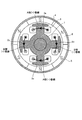
図8は、実施の形態2にかかる同期電動機の横断面図である。固定子1は、軸心を中心とする円柱状の鉄心に4n(nは自然数)個のティース2が遠心方向に向かって周方向に等角度間隔で形成され、この各ティース2a,2b,2c,2dに巻線が集中巻きで巻回され4n個のコイル3が形成されている。
FIG. 8 is a cross-sectional view of the synchronous motor according to the second embodiment. In the stator 1, 4n (n is a natural number)
各ティース2a,2b,2c,2dは、2n個ずつの2組に区分される。このとき、一方の組を成す各ティース(ここでは、各ティース2a,2c)と他方の組を成す各ティース(ここでは、各ティース2b,2d)とが交互に配置されるように区分される。各ティース2a,2b,2c,2dに巻回される巻線は、一方の組を成す各ティース(ここでは、各ティース2a,2c)に巻回される巻線と、他方の組を成す各ティース(ここでは、各ティース2b,2d)に巻回される巻線との2つに分離した2相の巻線としており、同じ組内において隣接する各ティース(ここでは、各ティース2a,2c、あるいは、各ティース2b,2d)に巻回する巻線の巻回方向を軸心から見て互いに逆方向としている。
Each
なお、図8に示す実線矢印は、各コイル3を形成する各巻線(A相(+)巻線、A相(−)巻線、B相(+)巻線、B相(−)巻線)に流れる正方向電流の向きを示している。また、各ティース2a,2b,2c,2dの先端幅は、実施の形態1と同様に、軸心を中心として機械角で略(45/n)°としている。
8 indicate the respective windings (A phase (+) winding, A phase (−) winding, B phase (+) winding, B phase (−) winding) forming each
回転子4は、軸心を中心とする円環状の軟磁性材料のバックヨーク5の内周面に、6n個の平行配向あるいはラジアル配向された永久磁石6が異なる極性を交互にして周方向に等角度間隔で配置され、各ティース2a,2b,2c,2dの外側に固定子1に対向して回転可能に配置されている。
The rotor 4 has 6 n parallel or radial-oriented
なお、図8に示す例では、n=1、つまり、固定子1の突極数(ティース数)が4、回転子4の極数が6である例を示している。なお、以下の説明において、各ティース2a,2b,2c,2dを特に区別する必要のない場合には、ティース2と称する。
In the example illustrated in FIG. 8, n = 1, that is, the number of salient poles (tooth number) of the stator 1 is 4, and the number of poles of the rotor 4 is 6. In the following description, the
本実施の形態にかかる同期電動機の動作、および各ティース2の先端幅を機械角で略(45/n)°とする技術的根拠については、実施の形態1と同様であるのでここでは説明を省略する。
Since the operation of the synchronous motor according to the present embodiment and the technical basis for setting the tip width of each
インナーロータ型の同期電動機とした実施の形態1の構成の場合、ティース2の先端幅を狭く(具体的には、回転子4の永久磁石6の磁極の幅(機械角で60°)よりも狭い45°)することにより、コギングトルクを低減できる反面、巻線に鎖交する磁束が減少して出力が低下する。
In the case of the configuration of the first embodiment, which is an inner rotor type synchronous motor, the tip width of the
上述したアウターロータ型の同期電動機とした本実施の形態の構成では、回転子4を固定子1の外周に配置することで、永久磁石6を大きくすることができるため、巻線に鎖交する磁束量を大きくすることができ、出力の低下を抑制することができる。
In the configuration of the present embodiment, which is the above-described outer rotor type synchronous motor, the
なお、実施の形態1のインナーロータ型の同期電動機の場合、巻線を収納するスロットの断面積は広くできるが、可能な限り多くの巻線を収納しようとしても、コイルエンドが大きくなるため、コイル3の形状が崩れやすくなり収納が難しく、また、巻線の抵抗も大きくなるため、効率改善効果が少ない。つまり、インナーロータ型の同期電動機では、スロットの断面積を有効に利用できないことが多い。
In addition, in the case of the inner rotor type synchronous motor of the first embodiment, the cross-sectional area of the slot for storing the winding can be widened, but the coil end becomes large even when trying to store as many windings as possible. Since the shape of the
これに対し、実施の形態2のアウターロータ型の同期電動機では、スロットの断面積が広く取れなくても、巻線の収納の容易性や巻線の抵抗を考慮すると、収納できる巻線の量は、実施の形態1のインナーロータ型の同期電動機に対して、極端に少なくなることはない。 On the other hand, in the outer rotor type synchronous motor according to the second embodiment, even if the slot cross-sectional area is not large, the amount of winding that can be stored is considered in consideration of the ease of storing the winding and the resistance of the winding. This is not extremely less than the inner rotor type synchronous motor of the first embodiment.
以上説明したように、実施の形態2の同期電動機によれば、アウターロータ型の同期電動機とすることにより、永久磁石を大きくすることができるので、実施の形態1のインナーロータ型の同期電動機よりも巻線に鎖交する磁束量を大きくすることができ、出力の低下を抑制することができる。 As described above, according to the synchronous motor of the second embodiment, since the permanent magnet can be enlarged by using the outer rotor type synchronous motor, the inner rotor type synchronous motor of the first embodiment can be used. In addition, the amount of magnetic flux interlinked with the winding can be increased, and the decrease in output can be suppressed.
また、以上の実施の形態に示した構成は、本発明の構成の一例であり、別の公知の技術と組み合わせることも可能であるし、本発明の要旨を逸脱しない範囲で、一部を省略する等、変更して構成することも可能であることは言うまでもない。 The configurations described in the above embodiments are examples of the configurations of the present invention, and can be combined with other known techniques, and a part of the configurations is omitted without departing from the gist of the present invention. Needless to say, it is possible to change the configuration.
1 固定子、2,2a,2b,2c,2d ティース、3 コイル、4 回転子、5 バックヨーク、6 永久磁石。 1 stator, 2, 2a, 2b, 2c, 2d teeth, 3 coils, 4 rotors, 5 back yoke, 6 permanent magnets.
Claims (5)
4n(nは自然数)個のティースが周方向に等角度間隔で形成され、前記各ティースに巻線が集中巻きで巻回された固定子と、
軟磁性材料のバックヨークの表面に、6n個の永久磁石が異なる極性を交互にして周方向に等角度間隔で配置され、前記固定子に対向配置された回転子と、
を備え、
前記各ティースの前記回転子に対向する部分の幅は、機械角で略(45/n)°であることを特徴とする同期電動機。 A synchronous motor driven by two-phase alternating currents having an electrical angle of 90 ° different from each other,
A stator in which 4n (n is a natural number) teeth are formed at equal angular intervals in the circumferential direction, and a winding is wound around each of the teeth by concentrated winding;
On the surface of the back yoke of soft magnetic material, 6n permanent magnets are alternately arranged with different polarities at equal angular intervals in the circumferential direction, and a rotor disposed opposite to the stator;
With
The synchronous motor according to claim 1, wherein a width of a portion of each tooth facing the rotor is substantially (45 / n) ° in mechanical angle.
前記回転子は、軸心を中心とする円柱状の前記バックヨークの外周面に、前記永久磁石が配置され、
前記各ティースの内側に前記固定子に対向して前記回転子が回転可能に配置されたインナーロータ型の構成であることを特徴とする請求項1〜3のいずれか一項に記載の同期電動機。 Each of the stators is formed in an annular iron core centered on the shaft center toward the shaft center.
In the rotor, the permanent magnet is disposed on the outer peripheral surface of the columnar back yoke centered on the axis.
The synchronous motor according to any one of claims 1 to 3, wherein the synchronous motor is configured to be an inner rotor type in which the rotor is rotatably disposed inside the teeth so as to face the stator. .
前記回転子は、軸心を中心とする円環状の前記バックヨークの内周面に、前記永久磁石が配置され、
前記各ティースの外側に前記固定子に対向して前記回転子が回転可能に配置されたアウターロータ型の構成であることを特徴とする請求項1〜3のいずれか一項に記載の同期電動機。 The stator is formed in a columnar iron core with an axial center as the teeth toward the centrifugal direction,
In the rotor, the permanent magnet is disposed on an inner peripheral surface of the annular back yoke centered on an axis.
The synchronous motor according to any one of claims 1 to 3, wherein the synchronous motor is configured as an outer rotor type in which the rotor is rotatably disposed opposite to the stator on the outside of each tooth. .
Priority Applications (1)
| Application Number | Priority Date | Filing Date | Title |
|---|---|---|---|
| JP2012159826A JP5619084B2 (en) | 2012-07-18 | 2012-07-18 | Synchronous motor |
Applications Claiming Priority (1)
| Application Number | Priority Date | Filing Date | Title |
|---|---|---|---|
| JP2012159826A JP5619084B2 (en) | 2012-07-18 | 2012-07-18 | Synchronous motor |
Publications (2)
| Publication Number | Publication Date |
|---|---|
| JP2014023279A JP2014023279A (en) | 2014-02-03 |
| JP5619084B2 true JP5619084B2 (en) | 2014-11-05 |
Family
ID=50197606
Family Applications (1)
| Application Number | Title | Priority Date | Filing Date |
|---|---|---|---|
| JP2012159826A Expired - Fee Related JP5619084B2 (en) | 2012-07-18 | 2012-07-18 | Synchronous motor |
Country Status (1)
| Country | Link |
|---|---|
| JP (1) | JP5619084B2 (en) |
Families Citing this family (1)
| Publication number | Priority date | Publication date | Assignee | Title |
|---|---|---|---|---|
| CN109861468B (en) * | 2019-03-15 | 2020-07-10 | 永嘉县麦通机械有限公司 | An automatic assembly machine for the external magnetic rotor of a magnetic pump |
Family Cites Families (4)
| Publication number | Priority date | Publication date | Assignee | Title |
|---|---|---|---|---|
| JP4626405B2 (en) * | 2005-06-01 | 2011-02-09 | 株式会社デンソー | Brushless motor |
| JP2007051909A (en) * | 2005-08-17 | 2007-03-01 | Tamagawa Seiki Co Ltd | Resolver |
| JP2009055698A (en) * | 2007-08-27 | 2009-03-12 | Aichi Elec Co | Rotor for permanent magnet type motor |
| CN102088234B (en) * | 2009-12-04 | 2015-07-01 | 德昌电机(深圳)有限公司 | Brushless direct-current motor |
-
2012
- 2012-07-18 JP JP2012159826A patent/JP5619084B2/en not_active Expired - Fee Related
Also Published As
| Publication number | Publication date |
|---|---|
| JP2014023279A (en) | 2014-02-03 |
Similar Documents
| Publication | Publication Date | Title |
|---|---|---|
| JP4926107B2 (en) | Rotating electric machine | |
| JP5682600B2 (en) | Rotating electrical machine rotor | |
| JP5774081B2 (en) | Rotating electric machine | |
| JP5449892B2 (en) | Permanent magnet excitation type radial magnetic bearing and magnetic bearing device including the radial magnetic bearing | |
| US7569962B2 (en) | Multi-phase brushless motor with reduced number of stator poles | |
| JP2013055872A (en) | Switched reluctance motor | |
| JP6138075B2 (en) | 2-phase synchronous motor | |
| JP6327803B2 (en) | High-power, high-efficiency single-phase multipolar generator | |
| CN106233584B (en) | Motor | |
| CN107078617B (en) | Double stator type rotator | |
| JP2018516061A (en) | Switched reluctance machine (SRM) with parallel flux paths | |
| CN113615041A (en) | Rotating electrical machine | |
| JP5460807B1 (en) | Synchronous motor | |
| JP2016067138A (en) | Dynamo-electric machine | |
| JP6589703B2 (en) | Rotating electric machine | |
| JP5619084B2 (en) | Synchronous motor | |
| KR101666931B1 (en) | Magnetic circuit with variable magnetic flux | |
| JP6096646B2 (en) | motor | |
| JP5611094B2 (en) | Rotating electric machine | |
| JP2017063594A (en) | Brushless motor | |
| JP2008178187A (en) | Polyphase induction machine | |
| JP6541532B2 (en) | Switched reluctance motor | |
| JP2014176137A (en) | Double stator type switched reluctance rotating machine | |
| KR101511908B1 (en) | Permanent magnet motor | |
| JP5340332B2 (en) | Rotating electric machine |
Legal Events
| Date | Code | Title | Description |
|---|---|---|---|
| A131 | Notification of reasons for refusal |
Free format text: JAPANESE INTERMEDIATE CODE: A131 Effective date: 20140107 |
|
| TRDD | Decision of grant or rejection written | ||
| A01 | Written decision to grant a patent or to grant a registration (utility model) |
Free format text: JAPANESE INTERMEDIATE CODE: A01 Effective date: 20140819 |
|
| A61 | First payment of annual fees (during grant procedure) |
Free format text: JAPANESE INTERMEDIATE CODE: A61 Effective date: 20140916 |
|
| R150 | Certificate of patent or registration of utility model |
Ref document number: 5619084 Country of ref document: JP Free format text: JAPANESE INTERMEDIATE CODE: R150 |
|
| R250 | Receipt of annual fees |
Free format text: JAPANESE INTERMEDIATE CODE: R250 |
|
| R250 | Receipt of annual fees |
Free format text: JAPANESE INTERMEDIATE CODE: R250 |
|
| R250 | Receipt of annual fees |
Free format text: JAPANESE INTERMEDIATE CODE: R250 |
|
| R250 | Receipt of annual fees |
Free format text: JAPANESE INTERMEDIATE CODE: R250 |
|
| R250 | Receipt of annual fees |
Free format text: JAPANESE INTERMEDIATE CODE: R250 |
|
| R250 | Receipt of annual fees |
Free format text: JAPANESE INTERMEDIATE CODE: R250 |
|
| R250 | Receipt of annual fees |
Free format text: JAPANESE INTERMEDIATE CODE: R250 |
|
| LAPS | Cancellation because of no payment of annual fees |