JP5615524B2 - Weight inspection device - Google Patents
Weight inspection device Download PDFInfo
- Publication number
- JP5615524B2 JP5615524B2 JP2009229812A JP2009229812A JP5615524B2 JP 5615524 B2 JP5615524 B2 JP 5615524B2 JP 2009229812 A JP2009229812 A JP 2009229812A JP 2009229812 A JP2009229812 A JP 2009229812A JP 5615524 B2 JP5615524 B2 JP 5615524B2
- Authority
- JP
- Japan
- Prior art keywords
- conveyor
- weighing
- article
- support plate
- inspection apparatus
- Prior art date
- Legal status (The legal status is an assumption and is not a legal conclusion. Google has not performed a legal analysis and makes no representation as to the accuracy of the status listed.)
- Active
Links
Images


Landscapes
- Sorting Of Articles (AREA)
Description
本発明は、コンベア上を移送中に物品の重量を計量する重量検査装置に関する。 The present invention relates to a weight inspection apparatus that measures the weight of an article while being transferred on a conveyor.
従来、ポテトチップス、キャンデー等の物品を所定重量範囲内の重量に計量して包装し、市場に出荷する工場の生産ラインには、例えば、組合せ秤等の計量機器と、包装機と、検査装置(X線異物検出装置、金属検出機、重量検査装置等)と、振分装置と、箱詰め装置とが備えられている。 Conventionally, for example, a weighing machine such as a combination weigher, a packaging machine, and an inspection device are used in a production line of a factory that weighs and packages articles such as potato chips and candy within a predetermined weight range and ships them to the market. (X-ray foreign matter detection device, metal detector, weight inspection device, etc.), a sorting device, and a boxing device are provided.
このような生産ラインにおいて、検査装置では、包装機等から搬送されてきた物品をコンベアで搬送しながら所定の検査に対応する処理を実施し、その処理結果に基づいて例えば良品であるか不良品であるかの判定を行い、その判定結果(検査結果)を振分装置に渡し、振分装置では、不良品と判定された物品をコンベア上から排除し、良品と判定された物品を下流側の装置へ送るように構成されている。 In such a production line, the inspection apparatus performs processing corresponding to a predetermined inspection while conveying the articles conveyed from the packaging machine or the like by a conveyor, and based on the processing result, for example, it is a non-defective product or a defective product. The determination result (inspection result) is passed to the sorting device, and in the sorting device, the articles determined as defective are excluded from the conveyor, and the articles determined as non-defective are downstream. Configured to be sent to other devices.
検査装置のうち、重量検査装置には、物品を搬送しながら重量を計測するための計量コンベアと、計量コンベアへ物品を送り込むための送込コンベアとを備えたものがある(例えば、特許文献1,2参照)。 Among the inspection devices, some weight inspection devices include a weighing conveyor for measuring the weight while conveying an article and a feeding conveyor for feeding the article to the weighing conveyor (for example, Patent Document 1). , 2).
さらに、重量検査装置の操作及び検査結果等の表示を行うための操作表示器が取り付けられた電装品収納ボックスが両コンベアの搬送方向に対し左手側あるいは右手側に取り付けられ、コンパクト化が図られた構成のものがある。この構成の場合、作業者は両コンベア上を搬送される物品と操作表示器とを同じ側から見ることができるように、操作表示器はその前面が両コンベア側を向くように電装品収納ボックスに取り付けられている。電装品収納ボックス内には制御装置が収納され、制御装置は送込コンベアや計量コンベアのコンベア駆動用モータ等と配線ケーブルで接続されている。 In addition, an electrical component storage box with an operation indicator for displaying the operation of the weight inspection device and inspection results is attached to the left or right hand side with respect to the conveying direction of both conveyors, thereby achieving compactness. There are things with different configurations. In the case of this configuration, the operation indicator is an electrical component storage box so that the front of the operation indicator faces the both conveyors so that the operator can see the articles conveyed on both conveyors and the operation indicator from the same side. Is attached. A control device is stored in the electrical component storage box, and the control device is connected to a conveyor driving motor of a feeding conveyor, a weighing conveyor, or the like by a wiring cable.
上記のような重量検査装置は、通常、その製造工場において、操作表示器の前面側に送込コンベア及び計量コンベアが配置されるように、上側部分に操作表示器を有する電装品収納ボックスが取り付けられた状態に組み立てられ、この組み立てられた状態で販売店や顧客へ出荷される。 The weight inspection apparatus as described above is usually attached to an electrical component storage box having an operation indicator on the upper part so that a feeding conveyor and a weighing conveyor are arranged on the front side of the operation indicator in the manufacturing factory. The assembled state is then shipped to a dealer or customer in this assembled state.
販売店で販売される重量検査装置は、それが使用される生産ラインによっては、物品の搬送方向を逆方向に変更しなければならない場合がある。また、顧客先での生産ラインの変更によって物品の搬送方向を逆方向に変更しなければならない場合もある。 A weight inspection apparatus sold in a store may have to change the conveyance direction of an article to the opposite direction depending on the production line in which it is used. In some cases, it is necessary to change the conveyance direction of the article in the reverse direction by changing the production line at the customer site.
このように物品の搬送方向を変更しなければならない場合、電装品収納ボックスを取り外して反対側に取り付ける方法と、計量コンベアと送込コンベアとを取り外して位置を入れ替える方法とがある。電装品収納ボックスを反対側に取り付ける場合には、配線の取外しや再接続等の作業も必要になる。また、計量コンベアと送込コンベアとの位置を入れ替える場合には、配線の取外しや再接続の作業や、計量コンベアと送込コンベアとの搬送面の高さが同レベルとなるように搬送面の高さの調整作業が必要となる。さらに、この場合には、所定の計量精度が得られていることを確認するための再検査を行う必要もある。いずれの方法によっても、その作業を販売店の従業員や顧客が行うことは困難であり、製造工場の従業員が出張して行うことになるが、製造工場の従業員が行っても作業に手間がかかり、数時間の作業時間が必要になる。 Thus, when the conveyance direction of articles | goods must be changed, there exist the method of removing an electrical equipment storage box and attaching to an opposite side, and the method of removing a measurement conveyor and a feeding conveyor and changing a position. When the electrical component storage box is attached to the opposite side, work such as wiring removal and reconnection is also required. In addition, when the positions of the weighing conveyor and the feeding conveyor are switched, the work of removing and reconnecting the wiring, and the height of the feeding surface of the weighing conveyor and the feeding conveyor should be the same level. Height adjustment work is required. Furthermore, in this case, it is necessary to perform a re-inspection to confirm that a predetermined weighing accuracy is obtained. Either way, it is difficult for dealer employees and customers to do the work, and the employees of the manufacturing plant do business trips. It takes time and requires several hours of work.
本発明は上記のような課題を解決するためになされたもので、物品の搬送方向の変更作業を容易かつ短時間で行うことができる重量検査装置を提供することを目的としている。 The present invention has been made to solve the above-described problems, and an object of the present invention is to provide a weight inspection apparatus that can easily and quickly change an article conveyance direction.
上記目的を達成するために、本発明の重量検査装置は、一方向に物品を搬送する送込コンベアと、前記送込コンベアの下流側に隣接して配置され、前記送込コンベアから搬送されてきた物品を前記一方向へ搬送する計量コンベアと、前記計量コンベアを支持し、前記計量コンベア上の物品の重量を計量する計量ユニットとを備えた重量検査装置であって、
前記計量コンベアを支持した状態の前記計量ユニットと前記送込コンベアとを支持する支持板が、取付手段によって架台に着脱自在に取り付けられている。
In order to achieve the above object, a weight inspection apparatus according to the present invention is arranged adjacent to a downstream side of an infeed conveyor that conveys an article in one direction and is conveyed from the infeed conveyor. A weight inspection apparatus comprising: a weighing conveyor that conveys the article in one direction; and a weighing unit that supports the weighing conveyor and measures the weight of the article on the weighing conveyor;
A support plate that supports the weighing unit and the feeding conveyor in a state of supporting the weighing conveyor is detachably attached to a gantry by an attaching means.
この構成によれば、1つの支持板によって、計量コンベア及び計量ユニットと送込コンベアとが支持されているので、支持板を架台から取り外して180度方向転換して取り付けるだけで物品の搬送方向を逆方向にすることができ、容易かつ短時間の作業で物品の搬送方向を変更することができる。 According to this configuration, since the weighing conveyor, the weighing unit, and the feeding conveyor are supported by one support plate, the conveyance direction of the article can be changed simply by removing the support plate from the gantry and changing the direction 180 degrees. The direction can be reversed, and the conveyance direction of the article can be easily changed in a short time.
また、前記計量ユニットの計量結果を表示する操作表示器が上側部分に取り付けられた電装品収納ボックスが、前記送込コンベア及び前記計量コンベアの近傍に、かつ前記操作表示器が前記送込コンベア及び前記計量コンベアより上方において前記送込コンベア及び前記計量コンベアのコンベア側に面するように配設され、前記電装品収納ボックスは、上側部分の上部筐体部と下側部分の下部筐体部とが連結されてなり、前記上部筐体部が前記下部筐体部に沿うように折り畳むことができるように構成されていてもよい。 In addition, an electrical component storage box having an operation indicator for displaying the measurement result of the weighing unit attached to the upper part is in the vicinity of the feeding conveyor and the weighing conveyor, and the operation indicator is the feeding conveyor and Arranged to face the feeding conveyor and the conveyor side of the weighing conveyor above the weighing conveyor, the electrical component storage box includes an upper casing portion in the upper portion and a lower casing portion in the lower portion. And the upper housing part may be configured to be folded along the lower housing part.
この構成によれば、電装品収納ボックスが送込コンベア及び計量コンベアの近傍に配設されてあっても、電装品収納ボックスを上部筐体部が下部筐体部に沿うように折り畳んだ状態とすることにより、搬送方向を逆にするための支持板の方向転換を容易に行うことができる。 According to this configuration, even when the electrical component storage box is disposed in the vicinity of the feeding conveyor and the weighing conveyor, the electrical component storage box is folded so that the upper housing portion is along the lower housing portion. By doing so, it is possible to easily change the direction of the support plate for reversing the transport direction.
本発明は、以上に説明した構成を有し、重量検査装置において、物品の搬送方向の変更作業を容易かつ短時間で行うことができるという効果を奏する。 The present invention has the above-described configuration, and produces an effect that, in the weight inspection apparatus, an operation of changing the article conveyance direction can be performed easily and in a short time.
以下、本発明の好ましい実施の形態を、図面を参照しながら説明する。なお、以下では全ての図面を通じて同一又は相当する要素には同一の参照符号を付して、その重複する説明を省略する。また、本発明は、以下の実施形態に限定されない。 Hereinafter, preferred embodiments of the present invention will be described with reference to the drawings. In the following description, the same or corresponding elements are denoted by the same reference symbols throughout all the drawings, and redundant description thereof is omitted. Further, the present invention is not limited to the following embodiment.
(実施形態)
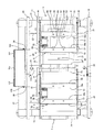
図1は、本発明の実施形態の重量検査装置の外観を示す斜視図であり、この図では計量コンベアCwのコンベアベルト30(図4参照)を図示していない。図2は、同重量検査装置の平面図であり、この図では送込コンベアCs及び計量コンベアCwの両コンベアベルト70,30(図4参照)を図示していない。図3(a)は、図1において矢印A方向から見た重量検査装置の側面図であり、図3(b)は、図1において矢印B方向から見た重量検査装置の側面図である。また、図4は、同重量検査装置の搬送方向を変更する方法を示す斜視図である。
(Embodiment)
FIG. 1 is a perspective view showing an appearance of a weight inspection apparatus according to an embodiment of the present invention. In this figure, the conveyor belt 30 (see FIG. 4) of the weighing conveyor Cw is not shown. FIG. 2 is a plan view of the same weight inspection apparatus, in which the
本実施形態の重量検査装置は、架台1と、この架台1に取り付けられた定盤(支持板)2と、送込コンベアCsと、計量コンベアCwと、計量ユニット6(図3)と、物品検出センサ25と、電装品収納ボックス10等を備えている。
The weight inspection apparatus according to the present embodiment includes a gantry 1, a surface plate (support plate) 2 attached to the gantry 1, a feed conveyor Cs, a weighing conveyor Cw, a weighing unit 6 (FIG. 3), and an article. A
この重量検査装置では、例えば、送込コンベアCsの前段に配置されたコンベア(図示せず)から送込コンベアCsへ搬送されてきた被検査物である物品は、送込コンベアCsから計量コンベアCwへ移送される。物品が送込コンベアCsから計量コンベアCwへ移送されたことは物品検出センサ25によって検出され、物品が計量コンベアCs上の所定位置に移送されてきたときに、計量コンベアCwを支持する計量ユニット6内の重量センサ63(図3)によって重量が計量され、この重量センサ63の計量信号は制御装置111へ入力される。
In this weight inspection apparatus, for example, an article that is an object to be inspected that has been conveyed from a conveyor (not shown) arranged in front of the feeding conveyor Cs to the feeding conveyor Cs is transferred from the feeding conveyor Cs to the weighing conveyor Cw. It is transferred to. It is detected by the
電装品収納ボックス10には、その前面の上部に操作表示器110が嵌め込まれるようにして取り付けられ、内部には制御装置111と、送込コンベアCs及び計量コンベアCwのモータの駆動回路(図示せず)等が収納されている。物品検出センサ25の検出信号及び重量センサ63の計量信号は制御装置111に入力される。
An
制御装置111は、例えばマイクロコンピュータ等によって構成され、本重量検査装置の動作の制御、例えばモータの駆動回路(図示せず)を介して送込コンベアCs及び計量コンベアCwの駆動及び停止の制御を行う。また、制御装置111には、物品検出センサ25の検出信号及び重量センサ63の計量信号が入力される。また制御装置111は、重量センサ63によって計量された物品の重量に基づいて、その重量が予め定められた複数の重量範囲のうちのどの重量範囲に属するかを判定し、その判定結果を本重量検査装置の後段に配置される振分装置へ送信する。また、制御装置111は、操作表示器110からの信号を入力するとともに、操作表示器110へその表示パネル110aに表示するデータ等の信号を出力する。
The
操作表示器110は、例えばタッチパネルディスプレイ等を用いて構成され、本重量検査装置の運転開始や運転停止等の操作等を行うための入力手段と、制御装置111から入力される計量結果である物品の重量値等を表示パネル110aに表示する表示手段とを備えている。
The
以下、本重量検査装置の構造について詳しく説明する。 Hereinafter, the structure of the weight inspection apparatus will be described in detail.
架台1には、取付手段であるボルト2Bによって定盤2が着脱自在に取り付けられている。定盤2には、送込コンベアCsが取り付けられるとともに、計量コンベアCwを支持した計量ユニット6が取り付けられている。また、架台1には、電装品収納ボックス10も取り付けられている。
A
架台1は、4本の脚部11〜14と、それぞれ2本の脚部間を連結する連結部15,16と、連結部15と連結部16とを連結し、定盤2が取り付けられる2本の水平フレーム17,18とを有している。また、一方の水平フレーム17にはアーム21,22が取り付けられ、アーム21,22の先端に保護用の棒状部材19が取り付けられている。同様に、他方の水平フレーム18にもアーム23,24が取り付けられ、アーム23,24の先端に保護用の棒状部材20が取り付けられている。棒状部材19、20には、物品が送込コンベアCsから計量コンベアCwへ移送されたことを検知するために光電センサを用いた物品検出センサ25が取り付けられている。さらに架台1は、その脚部12,14間を連結するフレーム27を有し、このフレーム27上に電装品収納ボックス10が固定されている。
The gantry 1 connects the four
図2に示すように、計量コンベアCwは、計量コンベア本体3とモータ4と計量コンベア受け部5とを備えている。
As shown in FIG. 2, the weighing conveyor Cw includes a weighing
計量コンベア本体3は、モータ4の回転がタイミングベルト等を介して伝動される駆動ローラ33と、従動ローラ34と、駆動ローラ33及び従動ローラ34を回転可能に支持するコンベアフレーム31,32と、駆動ローラ33及び従動ローラ34に張設されたコンベアベルト30(図4)とを備えている。符号41はタイミングベルトのカバーである。
The weighing
計量コンベア受け部5は、4枚の側板51〜54を備えている。前面側の側板51の一端側の上部にはフック部51a(図1)が設けられ、このフック部51aにコンベアフレーム31の一端部に突設されたピン35が係合し、側板51の他端側の上部とコンベアフレーム31の他端部とがパッチン錠37により固定されることにより、側板51とコンベアフレーム31とが固定されている。同様に、背面側の側板52の一端側の上部に設けられたフック部とコンベアフレーム32に突設されたピン36とが係合し、他端側がパッチン錠38により固定されることにより、側板52とコンベアフレーム32とが固定されている。モータ4は側板52の内側に固定されている。以上のようにして計量コンベア受け部5に計量コンベア本体3が取り付けられている。また、側板53、54の下端は折り曲げられてそれぞれ底板部53a,54aが形成されている。
The weighing
また、送込コンベアCsは、計量コンベヤCwへ物品を送り込むためのコンベヤであり、送込コンベア本体7とモータ8と送込コンベア受け部9とを備えている。
The feed conveyor Cs is a conveyor for feeding articles to the weighing conveyor Cw, and includes a
送込コンベア本体7は、計量コンベア本体3と同様の構成であり、モータ8の回転がタイミングベルト等を介して伝動される駆動ローラ73と、従動ローラ74と、駆動ローラ73及び従動ローラ74を回転可能に支持するコンベアフレーム71,72と、駆動ローラ73及び従動ローラ74に張設されたコンベアベルト70(図4)とを備えている。符号81はタイミングベルトのカバーである。
The feeding
送込コンベア受け部9も、計量コンベア受け部5と同様の構成であり、4枚の側板91〜94を備えている。また、計量コンベア受け部5及び計量コンベア本体3の場合と同様にして送込コンベア受け部9に送込コンベア本体7が取り付けられている。すなわち、前面側の側板91のフック部にコンベアフレーム71のピン75が係合するとともに、パッチン錠77の固定により、側板91とコンベアフレーム71とが固定され、背面側の側板92のフック部とコンベアフレーム72のピン76とが係合するとともに、パッチン錠78の固定により、側板92とコンベアフレーム72とが固定されている。また、モータ8は側板92の内側に固定されている。また、側板93、94の下端は折り曲げられてそれぞれ底板部93a,94aが形成されている。
The feeding
次に図3(a)に示すように、計量コンベアCwは、計量コンベア受け部5の底板部53a,54aのそれぞれが、計量ユニット6の2つの荷受部64にボルト66(図2)で固定されている。
Next, as shown in FIG. 3A, in the weighing conveyor Cw, each of the
計量ユニット6は、筐体61の内側にロードセルからなる重量センサ63が1個取り付けられ、4個の荷受部64にかかる荷重が重量センサ63により検出されるように、筐体61の内部に4個の荷受部64を連結する荷受金具(図示せず)が配設され、この荷受金具が重量センサ63に取り付けられている。筐体61は、4個の荷受部64を挿通する穴が設けられた金属板62に固定され、この金属板62は定盤2に2本のボルト65で固定されている(図2も参照)。図2に示すように。定盤2には、上方から計量ユニット6を挿通するための大きな開口部2cが設けられている。
The weighing
次に図3(b)に示すように、送込コンベアCsは、送込コンベア受け部9の底板部93a,94aが定盤2から浮いた状態で、底板部93a,94aのそれぞれが2本のボルト90によって定盤2に固定されている。
Next, as shown in FIG. 3B, the feed conveyor Cs includes two
以上の構成によって、計量コンベアCwは計量ユニット6に支持され、その計量ユニット6が定盤2に固定されている。また送込コンベアCsが定盤2に固定されている。
With the above configuration, the weighing conveyor Cw is supported by the weighing
定盤2は、架台1の水平フレーム17,18に5本ずつのボルト2B(図4)によって固定され、10本のボルト2Bを取り外すことによって架台1から取り外せることができる。定盤2には、コンベアCs,Cwの幅方向に対向する両縁部が下方に折り曲げられてなる持ち手部2a、2bが設けられている。
The
また、電装品収納ボックス10は、上側の上部筐体部10aと下側の下部筐体部10bとが2つの蝶番101によって連結され、下部筐体部10bが架台1のフレーム27上に固定されている。そして、一方の棒状部材20に取り付けられた2つの取付部材28に、下部筐体部10bの上部の両側側面がボルト102で固定されている。また、2つの取付部材28に、上部筐体部10aの下部の両側側面がボルト103で固定されており、このボルト103を取り外せば、上部筐体部10aは2つの蝶番101のみによって下部筐体部10bと連結された状態となり、図4に示すように、上部筐体部10aを回動させて下部筐体部10bに沿わせた状態にすることができる。
In the electrical
また、下部筐体部10bの前面側に設けられた穴(図示せず)と、水平フレーム18の中央に設けられた横穴18a(図4)とが電線管(プリカチューブ)104(図3)で連結されており、モータ4,8及び重量センサ63に接続された配線ケーブル105(図4)等が電線管104内を通って電装品収納ボックス10内の制御装置111に接続されている。ここで、モータ4,8に接続された配線ケーブルは、定盤2に設けられた穴等を通って定盤2の下方へ引き出され、重量センサ63に接続された配線ケーブルは、計量ユニット6から定盤2の下方へ引き出されており、これらの配線ケーブルは定盤2の中央の下方で束ねられ、さらに電線管104内を通って電装品収納ボックス10内の制御装置111に接続されている。
Further, a hole (not shown) provided on the front surface side of the
以上のように構成された重量検査装置において、物品の搬送方向を逆方向に変更する場合の作業について説明する。 In the weight inspection apparatus configured as described above, an operation in the case where the conveyance direction of the article is changed in the reverse direction will be described.
まず、電装品収納ボックス10の上部筐体部10aの下部の両側側面を固定するボルト103を取り外し、図4に示すように、上部筐体部10aを回動させて下部筐体部10bに沿わせた状態にする。これにより電装品収納ボックス10が折り畳まれた状態になる。
First, the
次に、定盤2を固定しているボルト2Bを全て取り外し、定盤2の持ち手部2a、2bを持って定盤2を上方へ持ち上げて、180度方向転換させた後、水平フレーム17,18上に降ろして、全てのボルト2Bを取り付ける。
Next, all the
その後、電装品収納ボックス10の上部筐体部10aを下部筐体部10b上に載せて2本のボルト103を取り付ける。
Thereafter, the
以上によって、物品の搬送方向を逆方向にする作業が終了する。この作業は、数分〜10分程度で行うことができ、非常に作業時間の短縮を図ることができる。なお、送込コンベアCsと計量コンベアCwとが一体的に方向転換されるので、送込コンベアCsと計量コンベアCwとの搬送面の高さの調整の必要がなく、計量精度の再検査も必要ない。 As described above, the work for changing the conveying direction of the article is completed. This operation can be performed in about several minutes to 10 minutes, and the operation time can be greatly shortened. In addition, since the feeding conveyor Cs and the weighing conveyor Cw are integrally changed in direction, it is not necessary to adjust the height of the conveying surface between the feeding conveyor Cs and the weighing conveyor Cw, and the weighing accuracy needs to be re-inspected. Absent.
本実施形態では、1つの定盤2に、計量コンベアCw及び計量ユニット6と送込コンベアCsとが支持されているので、定盤2を架台1から取り外して180度方向転換して取り付けるだけで物品の搬送方向を逆方向にすることができ、容易かつ短時間の作業で物品の搬送方向を変更することができる。また、作業が容易であるので、販売店の従業員や顧客が行うことも可能である。
In the present embodiment, since the weighing conveyor Cw and the weighing
さらに、本実施形態では、送込コンベヤCs及び計量コンベヤCwの近傍に配設された電装品収納ボックス10を図4に示す折り畳まれた状態とすることにより、上部筐体部10aを下方へ退避させることができ、定盤2の方向転換を容易に行うことができる。
Furthermore, in this embodiment, the upper housing | casing
なお、本実施形態では、定盤2を持ちやすくするため、定盤2を折り曲げて持ち手部2a、2bを設けているが、定盤2に取っ手を取り付けてもよい。本実施形態のように定盤2を折り曲げて持ち手部2a、2bを設けた場合には、定盤2の強度の向上にも寄与する。
In this embodiment, in order to make it easier to hold the
また、本実施形態では、定盤2をボルト2Bで固定するようにしたが、これに限られるものではない。例えば、パッチン錠を用いて定盤2を架台1に固定するようにしてもよい。
Moreover, in this embodiment, although the
また、物品検出センサ25も取付部材等を介して定盤2に固定されるように構成してもよい。物品検出センサ25は送込コンベア本体7と計量コンベア本体3との略境界上の物品を検出できるように取り付けられているが、物品検出センサ25を定盤2に固定することにより、送込コンベア本体7と計量コンベア本体3との長さが異なる場合に搬送方向を変更しても、物品検出センサ25の取付位置を変更する必要がない。言い換えれば、物品検出センサ25を定盤2に固定していなければ、送込コンベア本体7と計量コンベア本体3との長さが異なる場合に搬送方向を変更すれば、物品検出センサ25の取付位置を変更しなければならない。本実施形態では、物品検出センサ25を定盤2に固定していないが、送込コンベア本体7と計量コンベア本体3との長さが等しいため、搬送方向を変更しても物品検出センサ25の取付位置を変更する必要はない。
The
なお、搬送方向を逆にしたとき、配線ケーブル105にねじれが生じるが、それにより配線ケーブル105の接続部に負荷がかかり接続不良等の不具合が生じる場合には、配線ケーブル105の途中にコネクタを用いて接続及び切り離し可能なように構成してもよい。あるいは、柔軟性の高いケーブルを使用することにより配線ケーブル105の接続部への負荷を軽減するようにしてもよい。 Note that when the transport direction is reversed, the wiring cable 105 is twisted. If this causes a load on the connection portion of the wiring cable 105 and a problem such as poor connection occurs, connect the connector in the middle of the wiring cable 105. It may be configured to be connectable and disconnectable. Or you may make it reduce the load to the connection part of the wiring cable 105 by using a highly flexible cable.
本発明は、物品の搬送方向の変更作業を容易かつ短時間で行うことができる重量検査装置等として有用である。 INDUSTRIAL APPLICATION This invention is useful as a weight inspection apparatus etc. which can perform the change operation | work of the conveyance direction of articles | goods easily and in a short time.
Cs 送込コンベア
Cw 計量コンベア
1 架台
2 定盤(支持板)
2B ボルト
6 計量ユニット
10 電装品収納ボックス
10a 上部筐体部
10b 下部筐体部
25 物品検出センサ
28 取付部材
101 蝶番
102,103 ボルト
110 操作表示器
110a 表示パネル
Cs Feeding conveyor Cw Weighing conveyor 1
Claims (4)
前記計量コンベアを支持した状態の前記計量ユニットと前記送込コンベアとを支持する支持板が、取付手段によって架台に着脱自在に取り付けられ、
前記支持板は、物品の搬送方向を逆方向に変更するために180度向きを変えても、前記取付手段によって前記架台に着脱自在に取り付けられる、重量検査装置。 An infeed conveyor that conveys articles in one direction, a weighing conveyor that is arranged adjacent to the downstream side of the infeed conveyor, and that conveys articles conveyed from the infeed conveyor in the one direction, and the weighing conveyor And a weighing unit comprising a weighing unit for weighing the article on the weighing conveyor,
A support plate that supports the weighing unit and the feeding conveyor in a state of supporting the weighing conveyor is detachably attached to a gantry by attachment means ,
The weight inspection apparatus , wherein the support plate is detachably attached to the gantry by the attachment means even if the orientation of the support plate is changed by 180 degrees in order to change the conveyance direction of the article in the reverse direction .
前記支持板は、前記2本の水平フレームに着脱自在に取り付けられた、請求項1または2に記載の重量検査装置。 The weight inspection apparatus according to claim 1, wherein the support plate is detachably attached to the two horizontal frames.
前記支持板は、前記2本の水平フレームに着脱自在に取り付けられ、The support plate is detachably attached to the two horizontal frames,
前記計量ユニットは、前記支持板の下方で、かつ前記2本の水平フレームの間に配置され、The weighing unit is disposed below the support plate and between the two horizontal frames,
前記計量ユニットの計量結果を表示する操作表示器が上側部分に取り付けられた電装品収納ボックスが、前記操作表示器が前記送込コンベア及び前記計量コンベアより上方において前記送込コンベア及び前記計量コンベアのコンベア側に面するようにして、前記架台に固定された、請求項1または2に記載の重量検査装置。An electrical component storage box in which an operation indicator for displaying the measurement result of the weighing unit is attached to the upper portion, and the operation indicator is located above the feeding conveyor and the weighing conveyor, and is connected to the feeding conveyor and the weighing conveyor. The weight inspection apparatus according to claim 1, wherein the weight inspection apparatus is fixed to the frame so as to face a conveyor side.
Priority Applications (1)
| Application Number | Priority Date | Filing Date | Title |
|---|---|---|---|
| JP2009229812A JP5615524B2 (en) | 2009-10-01 | 2009-10-01 | Weight inspection device |
Applications Claiming Priority (1)
| Application Number | Priority Date | Filing Date | Title |
|---|---|---|---|
| JP2009229812A JP5615524B2 (en) | 2009-10-01 | 2009-10-01 | Weight inspection device |
Publications (2)
| Publication Number | Publication Date |
|---|---|
| JP2011075508A JP2011075508A (en) | 2011-04-14 |
| JP5615524B2 true JP5615524B2 (en) | 2014-10-29 |
Family
ID=44019637
Family Applications (1)
| Application Number | Title | Priority Date | Filing Date |
|---|---|---|---|
| JP2009229812A Active JP5615524B2 (en) | 2009-10-01 | 2009-10-01 | Weight inspection device |
Country Status (1)
| Country | Link |
|---|---|
| JP (1) | JP5615524B2 (en) |
Families Citing this family (4)
| Publication number | Priority date | Publication date | Assignee | Title |
|---|---|---|---|---|
| CN102795353B (en) * | 2012-08-14 | 2014-05-14 | 胡海明 | Electronic weighing device capable of automatically conveying cans |
| DE102013203460A1 (en) | 2013-02-28 | 2014-08-28 | Bizerba Gmbh & Co Kg | Frame of a weighing conveyor |
| CN103482145A (en) * | 2013-09-22 | 2014-01-01 | 芜湖万向新元环保科技有限公司 | Automatic weighing rail |
| JP6391110B2 (en) * | 2014-06-16 | 2018-09-19 | 株式会社エー・アンド・デイ | Weight inspection device |
Family Cites Families (3)
| Publication number | Priority date | Publication date | Assignee | Title |
|---|---|---|---|---|
| JPH0641955Y2 (en) * | 1987-10-14 | 1994-11-02 | アンリツ株式会社 | Weight sorter |
| JP4156786B2 (en) * | 2000-10-06 | 2008-09-24 | 株式会社イシダ | Quality inspection equipment |
| JP4008413B2 (en) * | 2003-12-26 | 2007-11-14 | アンリツ産機システム株式会社 | Weight sorter |
-
2009
- 2009-10-01 JP JP2009229812A patent/JP5615524B2/en active Active
Also Published As
| Publication number | Publication date |
|---|---|
| JP2011075508A (en) | 2011-04-14 |
Similar Documents
| Publication | Publication Date | Title |
|---|---|---|
| JP5615524B2 (en) | Weight inspection device | |
| KR101324275B1 (en) | Cargo volume checker | |
| JP5848880B2 (en) | Weighing device | |
| GB2165365A (en) | High-speed transporting and weighing machine | |
| JP5064973B2 (en) | Weight inspection device | |
| JP5284744B2 (en) | Weight sorter | |
| JP2009113888A (en) | Quality inspection device | |
| JP2013193158A (en) | Industrial robot | |
| JP4711300B2 (en) | Inspection equipment | |
| CN215623175U (en) | Visual detection and weighing integrated machine | |
| CN218099484U (en) | Chip testing device with limiting structure | |
| JP2004132839A (en) | Weight measuring conveyor and inspection system and article classification system using it | |
| JP7398798B2 (en) | Weighing device | |
| JP6486229B2 (en) | Weight inspection device | |
| KR101626825B1 (en) | Apparatus for sensing and indicating serpentine moving of conveyor belt | |
| JP4848257B2 (en) | Conveyor scale of belt conveyor | |
| KR101242381B1 (en) | Weighing chain conveyor | |
| JP2002039845A (en) | Weighing equipment | |
| JP2007101463A (en) | Weight-detecting device | |
| CN1754794B (en) | Conveyor device, and article testing unit having the same | |
| JP2002131117A (en) | Metering device | |
| JP2002102803A (en) | Scale with sorting function | |
| CN216486860U (en) | Comprehensive training examination platform for industrial robot | |
| JP3198402U (en) | Combination scale | |
| CN219785663U (en) | Weighing device and sorting equipment |
Legal Events
| Date | Code | Title | Description |
|---|---|---|---|
| A621 | Written request for application examination |
Free format text: JAPANESE INTERMEDIATE CODE: A621 Effective date: 20120906 |
|
| A977 | Report on retrieval |
Free format text: JAPANESE INTERMEDIATE CODE: A971007 Effective date: 20131217 |
|
| A131 | Notification of reasons for refusal |
Free format text: JAPANESE INTERMEDIATE CODE: A131 Effective date: 20131224 |
|
| A521 | Request for written amendment filed |
Free format text: JAPANESE INTERMEDIATE CODE: A523 Effective date: 20140206 |
|
| TRDD | Decision of grant or rejection written | ||
| A01 | Written decision to grant a patent or to grant a registration (utility model) |
Free format text: JAPANESE INTERMEDIATE CODE: A01 Effective date: 20140909 |
|
| A61 | First payment of annual fees (during grant procedure) |
Free format text: JAPANESE INTERMEDIATE CODE: A61 Effective date: 20140910 |
|
| R150 | Certificate of patent or registration of utility model |
Ref document number: 5615524 Country of ref document: JP Free format text: JAPANESE INTERMEDIATE CODE: R150 |
|
| R250 | Receipt of annual fees |
Free format text: JAPANESE INTERMEDIATE CODE: R250 |
|
| R250 | Receipt of annual fees |
Free format text: JAPANESE INTERMEDIATE CODE: R250 |
|
| R250 | Receipt of annual fees |
Free format text: JAPANESE INTERMEDIATE CODE: R250 |
|
| R250 | Receipt of annual fees |
Free format text: JAPANESE INTERMEDIATE CODE: R250 |
|
| R250 | Receipt of annual fees |
Free format text: JAPANESE INTERMEDIATE CODE: R250 |
|
| R250 | Receipt of annual fees |
Free format text: JAPANESE INTERMEDIATE CODE: R250 |
|
| R250 | Receipt of annual fees |
Free format text: JAPANESE INTERMEDIATE CODE: R250 |