JP5615086B2 - Imaging apparatus, control method thereof, and program - Google Patents
Imaging apparatus, control method thereof, and program Download PDFInfo
- Publication number
- JP5615086B2 JP5615086B2 JP2010178760A JP2010178760A JP5615086B2 JP 5615086 B2 JP5615086 B2 JP 5615086B2 JP 2010178760 A JP2010178760 A JP 2010178760A JP 2010178760 A JP2010178760 A JP 2010178760A JP 5615086 B2 JP5615086 B2 JP 5615086B2
- Authority
- JP
- Japan
- Prior art keywords
- display unit
- display
- live view
- view image
- level guide
- Prior art date
- Legal status (The legal status is an assumption and is not a legal conclusion. Google has not performed a legal analysis and makes no representation as to the accuracy of the status listed.)
- Expired - Fee Related
Links
Images


Description
本発明は、デジタルカメラ等の撮像装置、その制御方法、プログラム及びコンピュータ読み取り可能な記録媒体に関する。 The present invention relates to an imaging apparatus such as a digital camera, a control method thereof, a program, and a computer-readable recording medium.
従来、デジタルカメラ等の撮像装置において、ユーザがカメラを水平に構えるための水準器ガイド表示機能を備えたものが実現されている。また、表示面の向きを前後左右に自由に変えられる表示ユニットを備えたものも実現されている。 2. Description of the Related Art Conventionally, an imaging apparatus such as a digital camera having a level guide display function for a user to hold the camera horizontally has been realized. In addition, a display unit that can freely change the direction of the display surface from front to back and from side to side is realized.
この種の撮像装置では、一般的に、表示ユニットが被写体側に向いているときに、表示ユニットが背面側に向いているときと同じ表示をしたり、ライブビュー画像に従った表示をしたりする技術が開発されている。例えば特許文献1には、表示部が対面撮影用に回転可能なものであれば、表示制御部は表示部の回転に応じて、音声インジケータの表示も反転させることが開示されている。具体的には、例えば撮影画像の上下または左右の表示を切り替えると共に、音声インジケータの表示位置の上下または左右の表示位置を切り替える。
In this type of imaging device, in general, when the display unit is facing the subject, the same display as when the display unit is facing the back side is performed, or the display according to the live view image is performed. Technology has been developed. For example,
しかしながら、表示ユニットに水準器ガイドを表示する際に、表示ユニットの向きに応じて水準器ガイドを適切に表示するための技術はいまのところない。例えば図11(a)、(b)に示すように、背面側に向いていた表示ユニット417を被写体側に向ける場合に、水準器ガイドの水平線1101をそのまま表示すると、水平線1101の傾きが左右反転になる。そのため、水平線1101に従ってカメラを調整すると、より傾いてしまい、不便であった。
However, when displaying the level guide on the display unit, there is currently no technique for appropriately displaying the level guide according to the orientation of the display unit. For example, as shown in FIGS. 11A and 11B, when the
そのような不都合を避けるために、表示ユニット417の向きに応じて表示アイテムを反転する構成も考えられる。しかしながら、全ての表示アイテムを反転すると、文字及びアイコンといった所定の表示アイテムが見にくいものとなるおそれがある。
In order to avoid such an inconvenience, a configuration in which the display item is inverted according to the orientation of the
本発明は、上記のような点に鑑みてなされたものであり、文字及びアイコンといった所定の表示アイテムと水準器ガイドとを表示ユニットの向きに応じてそれぞれ適切に表示できるようにすることを目的とする。 The present invention has been made in view of the above points, and it is an object of the present invention to appropriately display predetermined display items such as characters and icons and a level guide according to the orientation of the display unit. And
本発明の撮像装置は、撮像装置本体と、前記撮像装置本体内に設けられた撮像手段と、前記撮像装置本体に対して複数の位置に移動可能に取り付けられた表示ユニットと、姿勢検知手段と、前記撮像手段により撮像されたライブビュー画像と、前記姿勢検知手段による姿勢検知情報を表わす水準器ガイドを、前記表示ユニットの位置に応じて、前記表示ユニットに表示させる制御手段とを備え、前記制御手段は、前記表示ユニットの位置に応じて、前記ライブビュー画像を反転させて表示させ、さらに、前記表示ユニットが第1の位置の場合には、前記ライブビュー画像に対する前記水準器ガイドの表示状態が所定の状態となるように表示させ、前記表示ユニットが第2の位置の場合には、前記ライブビュー画像に対する前記水準器ガイドの表示状態が前記所定の状態から左右反転した状態で表示されるように制御することを特徴とする。 Imaging apparatus of the present invention includes an imaging apparatus main body, and an imaging means provided in the image pickup apparatus main body, a display unit attached movably in a plurality of positions with respect to the imaging apparatus main body, and the posture detecting means Control means for displaying a live view image picked up by the image pickup means and a level guide representing posture detection information by the posture detection means on the display unit according to the position of the display unit, The control means inverts and displays the live view image in accordance with the position of the display unit, and further, when the display unit is at the first position, displays the level guide for the live view image. When the display unit is in the second position, the level guide is displayed for the live view image. It shows state and controls to be displayed in a state of horizontally reversed from the predetermined state.
本発明によれば、文字及びアイコンといった所定の表示アイテムと水準器ガイドとを表示ユニットの向きに応じてそれぞれ適切に表示することができる。したがって、表示ユニットがどの向きにあっても、所定の表示アイテムが見にくいものとなることがなく、かつ、水準器ガイドを見てカメラの姿勢を調整すると正しく水平にすることができる。 According to the present invention, predetermined display items such as characters and icons and a level guide can be appropriately displayed according to the orientation of the display unit. Therefore, the display unit does not become difficult to see regardless of the orientation of the display unit, and can be correctly leveled by adjusting the posture of the camera while looking at the level guide.
以下、添付図面を参照して、本発明の好適な実施形態について説明する。
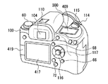
図1は本発明の実施形態に係る撮像装置の外観図、図2は撮像装置の内部構成図である。図1、2に示す撮像装置はデジタル一眼レフカメラ(以下、カメラという)として構成されている。カメラ本体(撮像装置本体)100の上部には、アクセサリシュー110、光学ファインダ104、レリーズボタン114が設けられている。レリーズボタン114は、撮像動作を指示するために用いられる。
Preferred embodiments of the present invention will be described below with reference to the accompanying drawings.
FIG. 1 is an external view of an imaging apparatus according to an embodiment of the present invention, and FIG. 2 is an internal configuration diagram of the imaging apparatus. 1 and 2 is configured as a digital single-lens reflex camera (hereinafter referred to as a camera). An
また、カメラ本体100の上部には、メイン電子ダイヤル115、モードダイヤル60、外部表示ユニット409も設けられている。メイン電子ダイヤル115は、他の操作ボタンと共に操作されることによって、カメラ動作に関する数値を入力したり、撮像モードを切換えたりするために用いられる。外部表示ユニット409は、液晶パネル等により構成され、シャッタスピード値、絞り値、撮像モード等の撮影条件その他の情報を表示する。
A main
カメラ本体100の背面には、バリアングルTFT液晶モニタ(以下、単にバリアングル液晶モニタと称する)417、ヒンジ419が設けられている。また、LV(ライブビューボタン)68、Infoボタン66、サブ電子ダイヤル116、SETボタン117、電源スイッチ72が設けられている。また、不図示であるが十字キーやマルチコントローラ等の操作部材も設けられている。
A vari-angle TFT liquid crystal monitor (hereinafter simply referred to as a vari-angle liquid crystal monitor) 417 and a
バリアングル液晶モニタ417は、ヒンジ419を介して表示面の向きを前後左右に自由に変えられる表示ユニットであり、撮影により得られた画像(画像データ)や各種設定画面等を表示するために利用される。バリアングル液晶モニタ417は、透過型LCDで構成され、バックライト416(図2を参照)を有する。なお、バリアングル液晶モニタ417は、設定或いは処理可能な各種の設定、処理等を指定するためのメニュー画面や、後述するLV撮影画面(図11を参照)を表示する表示器としても利用される。ヒンジ419は、カメラ本体100とバリアングル液晶モニタ417を接続し、横回転及び縦回転をすることによりバリアングル液晶モニタ417の向きを変えることができる。
The vari-angle
LVボタン68は、バリアングル液晶モニタ417にライブビュー表示させる際に利用される。Infoボタン66は、バリアングル液晶モニタ417に表示している情報の表示状態を変更させる際に利用される。例えば、LV撮影画面ではInfoボタン66を押下するごとに情報表示が変更され、その中の一表示状態に姿勢検知情報を表わす水準器ガイド表示が存在する。
The
カメラ本体100の前面にはマウント106(図3を参照)が設けられており、このマウント106には、交換レンズ300に設けられたマウント306が着脱可能に結合する。図2において、500は撮像光軸を示す。交換レンズ300には、複数のレンズにより構成されるレンズユニット310、絞り312が設けられている。
A mount 106 (see FIG. 3) is provided on the front surface of the
カメラ本体100の内部において、撮像光路内にミラー130が配置されている。このミラー130は、レンズユニット310からの被写体光をファインダ光学系に向けて反射する位置(図2に示す位置)と、撮像光路外に退避する位置との間で移動可能となっている。ピント板150上には、ミラー130で反射された被写体光によって被写体像が形成される。
Inside the
また、カメラ本体100の内部において、ペンタゴナルダハプリズム132が配置されている。ペンタゴナルダハプリズム132は、ピント板150及びコンデンサレンズ152を通った被写体光を接眼レンズ154に導く。これらピント板150〜接眼レンズ154によって光学ファインダ104が構成される。ユーザは、接眼レンズ154を通してピント板150上に形成された被写体像を観察することができる。
A
後幕156及び先幕164は、それぞれフォーカルプレンシャッタ12(図3を参照)を構成する。これら後幕156及び先幕164の開放制御により、撮像素子14が必要な時間だけ露光される。撮像素子14は、CCDセンサやCMOSセンサにより構成され、その前面には光学ローパスフィルタ162が配設されている。また、撮像素子14は、プリント基板160に接続されている。このプリント基板160の後方には、表示基板158が配置されている。カメラ本体100とヒンジ419によりバリアングル液晶モニタ417及びバックライト416が接続されている。
The
カメラ本体100には、撮像動作で得られた画像データを記録する記録媒体200や付属装置210(図3を参照)が装着される。また、カメラ本体100には、二次電池86が装着される。記録媒体200、付属装置210及び電池86は、カメラ本体100に対して着脱が可能である。
The
次に、図3を参照して、カメラ本体100及び交換レンズ300の回路構成を説明する。なお、図3において、図1及び図2に示した構成要素については同一の符号を付す。
まず、交換レンズ300内の回路構成について説明する。交換レンズ300には、この交換レンズ300をカメラ本体100と電気的に接続するためのコネクタ322及びインタフェース320が設けられている。コネクタ322及びインタフェース320は、カメラ本体100に設けられたコネクタ122及びインタフェース120を介して、後述するレンズシステム制御回路350とカメラ本体100内のシステム制御回路50との通信を可能とする。
Next, the circuit configuration of the
First, a circuit configuration in the
絞り制御部340は、絞り312を制御する絞り制御部である。絞り制御部340は、後述する測光制御部46からの測光情報に基づいて、シャッタ制御部40と連携しながら絞り312を制御する。フォーカス制御部342は、レンズユニット310のフォーカス動作を制御する。ズーム制御部344は、レンズユニット310の変倍動作を制御する。
The
レンズシステム制御回路350は、交換レンズ300の各種動作を全体的に制御する。レンズシステム制御回路350は、各種動作用の定数、変数、コンピュータプログラム等を記憶するメモリを備えている。
The lens
次に、カメラ本体100内の回路構成について説明する。レンズユニット310及び絞り312を通過した被写体光は、ミラー130が撮像光路外に退避した状態(ミラー130がハーフミラーである場合は撮像光路内に配置された状態)で、開放されたフォーカルプレンシャッタ12を通過して撮像素子14に入射される。撮像素子14は、入射された被写体光を光電変換し、アナログの画像信号として出力する。A/D変換器16は、撮像素子14から出力されるアナログ信号(画像信号)をデジタル信号に変換する。タイミング発生回路18は、メモリ制御回路22及びシステム制御回路50の制御の下に、撮像素子14、A/D変換器16及びD/A変換器26にクロック信号や制御信号を供給する。
Next, a circuit configuration in the
画像処理回路20は、A/D変換器16からの画像データ又はメモリ制御回路22からの画像データに対して、画素補間処理や色変換処理を行う。また、画像処理回路20は、A/D変換器16から出力される画像データを用いて所定の演算処理を行う。システム制御回路50は、この演算結果に基づいて、シャッタ制御部40及び焦点調節部42を制御するためのTTL方式のオートフォーカス(AF)処理、自動露出(AE)処理及びフラッシュプリ発光(EF)処理を行う。さらに、画像処理回路20は、A/D変換器16から出力される画像データを用いて所定の演算処理を行い、この演算結果に基づいてTTL方式のオートホワイトバランス(AWB)処理も行う。
The
メモリ制御回路22は、A/D変換器16、タイミング発生回路18、画像処理回路20、画像表示メモリ24、D/A変換器26、メモリ30及び圧縮・伸長回路32を制御する。A/D変換器16から出力された画像データは、画像処理回路20及びメモリ制御回路22を介して、又はメモリ制御回路22のみを介して画像表示メモリ24又はメモリ30に書き込まれる。
The
画像表示部28は、D/A変換器26によりアナログ信号に変換され、画像表示メモリ24に書き込まれた画像信号を、図1及び図2に示したバリアングル液晶モニタ417に逐次表示することで、電子ビューファインダ(EVF)機能を実現する。なお、画像表示部28は、システム制御回路50の指示により、電子ビューファインダ(EVF)機能をON/OFFする。
The
メモリ30は、撮像に係る静止画像を格納する。また、メモリ30は、動画撮影時に所定レートで連続的に記録媒体200、付属装置210書き込まれる画像のフレームバッファとして使用される。さらに、メモリ30は、システム制御回路50の作業領域としても使用される。
The
圧縮・伸長回路32は、公知の画像圧縮方法を用いて画像データを圧縮・伸長する。圧縮・伸長回路32は、メモリ30に格納された画像を読み込んで圧縮処理又は伸長処理を行い、処理を終えたデータを再びメモリ30に書き込む。
The compression /
シャッタ制御部40は、測光制御部46からの測光情報に基づいて、絞り制御部340と連携しながら、フォーカルプレンシャッタ12のシャッタ速度を制御する。焦点調節部42は、ミラー130を透過して不図示のサブミラーによって導かれた被写体像の位相差を検出することで、AF処理を行う。測光制御部46は、不図示の測光センサからの出力信号に基づいて、AE処理を行う。フラッシュ48は、AF補助光の投光機能やフラッシュ調光機能を有する。なお、測光制御部46は、フラッシュ48と連携して、EF処理を行う。
The
システム制御回路50は、CPUやメモリを含み、カメラ本体100の動作を全体的に制御する。メモリ52には、システム制御回路50の動作用の定数、変数、コンピュータプログラム(基本プログラム)等が記憶される。
The
通知部54は、システム制御回路50でのコンピュータプログラムの実行に応じて、文字、画像をLCDやLED等により表示したり、音声をスピーカ(図示省略)から発したりして、カメラの動作状態やメッセージ等を外部に通知する。この通知部54には、光学ファインダ104内に絞り値、シャッタ速度、合焦度、手振れ警告、露出補正値等の表示を行うLCDユニットが含まれる。
The
不揮発性メモリ56は、例えば電気的に消去・記録可能なEEPROM等で構成され、コンピュータプログラム等の格納用メモリとして使用される。この場合、当然ながら、コンピュータプログラムは、コンピュータ読取可能に不揮発性メモリ56に格納される。このコンピュータプログラムには、後述する図4〜図9のフローチャートに係るコンピュータ実行可能に構成されたアプリケーションプログラムが含まれる。不揮発性メモリ56には、メニュー画面等のGUI画面上で設定された設定値、メイン電子ダイヤル115、サブ電子ダイヤル116の操作で設定された設定値、モードダイヤル60の操作で指定された撮影モード情報等も格納される。
The
シャッタスイッチ(SW1)62は、レリーズボタン114の第1ストローク操作(半押し)によってONとなり、AF処理、AE処理、AWB処理、EF処理等の動作開始をシステム制御回路50に指示する。シャッタスイッチ(SW2)64は、レリーズボタン114の第2ストローク操作(全押し)によってONとなり、露光処理、現像処理及び記録処理からなる一連の撮像処理の動作開始をシステム制御回路50に指示する。
The shutter switch (SW1) 62 is turned on by the first stroke operation (half-press) of the
Infoボタン66は、情報表示の種類をシステム制御回路50に指示するために操作される。システム制御回路50は、情報表示の種類変更指示を受けて、撮影条件等を不揮発性メモリ56から読み出して情報表示画面を作成し、バリアングル液晶モニタ417に表示する。LVボタン68は、LV表示の開始及び終了を指示するために操作される。操作部70は、Infoボタン66、LVボタン68等の各種ボタンや、メイン電子ダイヤル115、サブ電子ダイヤル116、モードダイヤル60等の各種ダイヤルを含む。システム制御回路50は、操作部70からの信号に応じて各種動作を行う。
The
電源スイッチ72は、カメラ本体100の電源のON/OFFを切換えるためのスイッチである。また、電源スイッチ72の操作によって、カメラ本体100に接続された交換レンズ300、外部フラッシュ、記録媒体200及び他の付属装置(パーソナルコンピュータ等)210の電源のON/OFFも同時に切換えることができる。
The
横回転検知スイッチ74は、ヒンジ419が標準位置にある場合はOFF、横回転した場合はONを通知する。縦回転検知スイッチ76は、ヒンジ419が標準位置にある場合はOFF、縦回転した場合はONを通知する。
The lateral rotation detection switch 74 notifies OFF when the
電源制御部80は、電池検出回路、DC−DCコンバータ、通電するブロックを切換えるスイッチ回路等により構成される。電源制御部80は、電池の装着の有無、電池の種類及び電池残量の検出を行い、その検出結果及びシステム制御回路50の指示に基づいてDC−DCコンバータを制御し、必要な電圧を必要な期間、記録媒体200を含む各部に供給する。
The
コネクタ82、84は、電池86からの電力をカメラ本体100、交換レンズ300、外部フラッシュ、記録媒体200及び他の付属装置210に供給する。カメラ本体100には、記録媒体200及び付属装置210のインタフェース90、94、記録媒体200や付属装置210との接続を行うコネクタ92、96を備える。着脱検知回路78、98は、コネクタ92、96に記録媒体200や付属装置210が装着されているか否かを検出する。
The
記録媒体200は、メモリカードやハードディスク等の記録媒体であり、半導体メモリや磁気ディスク等から構成される記録部202、カメラ本体100とのインタフェース204、カメラ本体100と接続を行うコネクタ206を備える。同じく、付属装置210は、半導体メモリや磁気ディスク等から構成される記録部212、カメラ本体100とのインタフェース214、カメラ本体100と接続を行うコネクタ216を備える。
The
ここで、図10を参照して、カメラ本体100とバリアングル液晶モニタ417との位置関係を説明する。カメラ本体100とバリアングル液晶モニタ417との位置の変更は、ユーザがヒンジ419を回転することにより行われる。図10(a)は、バリアングル液晶モニタ417がカメラ本体100の背面に収まっている、第1の位置の状態である。
Here, the positional relationship between the
図10(b)は、バリアングル液晶モニタ417が被写体側に向いている、第2の位置の状態である。図10(a)の状態から180度の横回転(カメラ本体100に対して垂直な方向を回転軸として180度回転)で図10(b)の状態になる。すなわち、第2の位置は、第1の位置を基準とすると、バリアングル液晶モニタ417をカメラ本体100に対して垂直な方向を回転軸として180度回転した位置である。そして、第2の位置にあるバリアングル液晶モニタ417の表示面は、第1の位置にあるバリアングル液晶モニタ417の表示面と180度反対向きである。
FIG. 10B shows the second position where the vari-angle liquid crystal monitor 417 faces the subject. From the state of FIG. 10A, the state is changed to the state of FIG. 10B by lateral rotation of 180 degrees (rotating 180 degrees with the direction perpendicular to the
図10(c)は、バリアングル液晶モニタ417がカメラ本体100の背面側に向いている、第3の位置の状態である。図10(b)の状態から180度の縦回転(カメラ本体100に対して水平な方向を回転軸として180度回転)で図10(c)の状態になる。すなわち、第3の位置は、第1の位置を基準とすると、バリアングル液晶モニタ417をカメラ本体100に対して垂直な方向を回転軸として180度回転し、かつ、カメラ本体100に対して水平な方向を回転軸として180度回転した位置である。そして、第3の位置にあるバリアングル液晶モニタ417の表示面は、第1の位置にあるバリアングル液晶モニタ417の表示面と同じ向きである。
FIG. 10C shows a third position where the vari-angle liquid crystal monitor 417 faces the back side of the
次に、図11を参照して、バリアングル液晶モニタ417に表示するLV撮影画面の例について説明する。図11(a)は、バリアングル液晶モニタ417が第1の位置(図10(a))にあるときのLV撮影画面である。図11(b)は、バリアングル液晶モニタ417が第2の位置(図10(b))にあるときに、第1の位置で表示したLV撮影画面をそのままとしたときの表示である。図11(c)は、バリアングル液晶モニタ417が第2の位置(図10(b))にあるときに、本発明を適用した対策を行ったときの表示である。図11(b)では、撮影者が立っている地面に対して水準器ガイドの水平線1101が平行になっていない。それに対して、対策を行った表示(図11(c))では、撮影者が立っている地面に対して水準器ガイドの水平線1101が平行になっている。
Next, an example of the LV shooting screen displayed on the vari-angle liquid crystal monitor 417 will be described with reference to FIG. FIG. 11A shows an LV shooting screen when the vari-angle
次に、図12を参照して、水準器ガイド表示の詳細について説明する。この表示例では、水平、あおり方向の水準を表示している。図12(a)は、カメラの姿勢を正位置又は上下反転したときの表示例である。図12(b)は、カメラの姿勢を90度回転又は270度回転したときの表示例である。 Next, details of the level guide display will be described with reference to FIG. In this display example, levels in the horizontal and tilt directions are displayed. FIG. 12A shows a display example when the posture of the camera is the normal position or upside down. FIG. 12B is a display example when the posture of the camera is rotated 90 degrees or 270 degrees.
1201は水平方向の水準を表すための補助線であり、ユーザがカメラの姿勢を変更しなければ、同じ位置に表示される。1202は水平線であり、地面と平行に表示され、傾きがある場合は例えば赤色、水平の場合は補助線1201と重なって例えば緑色で表示される。
1201 is an auxiliary line for representing the level in the horizontal direction, and is displayed at the same position unless the user changes the posture of the camera.
1203はあおり方向の補助線であり、ユーザがカメラの姿勢を変更しなければ、同じ位置に表示される。1204はあおり位置であり、あおりの傾きによって図12(a)の場合は上下に、図12(b)の場合は左右に移動する。
1203 is an auxiliary line in the tilt direction, and is displayed at the same position unless the user changes the posture of the camera.
1205は水平方向の水準を合わせるために、カメラを傾ける方向を表したガイダンス表示である。図示例の場合、カメラを時計回りに回すと、水平になる。1206は、バリアングル液晶モニタ417の向きを表すガイダンス用のアイコンである。図示例の場合、バリアングル液晶モニタ417はレンズが付いている側、すなわち被写体側に向いていることを表している。
1205 is a guidance display showing the direction in which the camera is tilted in order to adjust the level in the horizontal direction. In the case of the illustrated example, when the camera is rotated clockwise, it becomes horizontal.
次に、図4を参照して、LV撮影モードの処理の概要を説明する。ユーザがLVボタン68を押下してLV撮影画面の表示指示を行うと、システム制御回路50は、LV撮影画面の表示に必要な初期データを不揮発性メモリ56から取得する(ステップS401)。LV撮影画面の表示に必要な初期データとしては、LV情報表示の情報表示レベル、ヒンジ419の回転スイッチ情報、外部出力端子の接続状態がある。また、このときの処理としては、水準器情報取得開始指示やフラグの初期化がある。この初期データ取得処理の詳細は図5を用いて後述する。
Next, an overview of the processing in the LV shooting mode will be described with reference to FIG. When the user presses the
次に、システム制御回路50は、撮影モード、AFモード、ISO等撮影に必要なデータを不揮発性メモリ56から取得する。また、システム制御回路50が測光情報等に基づいて算出したシャッタ速度、絞り値等のデータを取得する(ステップS402)。
Next, the
次に、システム制御回路50は、ヒンジ419の回転スイッチ状態及び外部出力端子の接続状態に基づいて、LV撮影画面に表示する情報の座標を求める(ステップS403)。この表示座標取得処理の詳細は図6を用いて後述する。
Next, the
次に、システム制御回路50は、LV情報表示の情報表示レベルに基づいて、LV撮影画面に必要な情報を表示する(ステップS404)。このLV情報表示処理の詳細は図7を用いて後述する。
Next, the
LV撮影画面を表示中にユーザが何らかの操作を行った場合、システム制御回路50は、その操作の内容を判別し、操作に合った処理を行う(ステップS405)。この操作毎の処理の詳細は図8を用いて後述する。
When the user performs any operation while the LV shooting screen is displayed, the
システム制御回路50は、LV撮影画面を終了するか継続するかを示す撮影モード終了フラグの内容を判別する(ステップS406)。その結果、撮影モード終了フラグが「1」の場合は、システム制御回路50はLV撮影モードの終了処理を行い(ステップS407)、処理を終了する。この終了処理の詳細は図9を用いて後述する。一方、撮影モード終了フラグが「1」以外の場合は、ステップS402に戻る。
The
図5は、図4のステップS401における初期データ取得処理の詳細を示すフローチャートである。初期データ取得処理では、システム制御回路50は、まず、不揮発性メモリ56から、LV情報表示の情報表示レベルを読み込む(ステップS501)。そして、その情報表示レベルが水準器ガイドを表示する「3」であるか否かを判別する(ステップS502)。その結果、合致した場合はステップS503に進み、合致しなかった場合はステップS504に進む。
FIG. 5 is a flowchart showing details of the initial data acquisition process in step S401 of FIG. In the initial data acquisition process, the
次に、システム制御回路50は、水準器情報を定期的に配信してもらうための、水準器情報取得開始処理を行う(ステップS503)。水準器情報は、水準器情報取得開始処理の後、水準器情報取得終了処理までの間、定期的に配信される。
Next, the
次に、システム制御回路50は、横回転検知スイッチ74から横回転スイッチ状態を取得して横回転フラグにセットする(ステップS504)。また、システム制御回路50は、縦回転検知スイッチ76から縦回転スイッチ状態を取得して縦回転フラグにセットする(ステップS505)。そして、外部出力端子着脱検知回路から外部出力端子の接続状態を取得して外部出力フラグにセットし(ステップS506)、出力変更フラグに「あり」、終了フラグに「0」をセットして初期化を行い(ステップS507)、本処理を終了する。
Next, the
図6は、図4のステップS403における表示座標取得処理の詳細を示すフローチャートである。表示座標取得処理では、システム制御回路50は、まず、出力変更フラグが「あり」であるか否かを判定する(ステップS601)。その結果、合致した場合はステップS602に進み、合致しなかった場合は本処理を終了する。
FIG. 6 is a flowchart showing details of the display coordinate acquisition processing in step S403 of FIG. In the display coordinate acquisition process, the
ステップS601において合致した場合、システム制御回路50は、外部出力フラグが「ON」であるか否かを判定する(ステップS602)。その結果、合致した場合はステップS604に進み、合致しなかった場合はステップS603に進む。
If they match in step S601, the
ステップS602において合致しなかった場合、システム制御回路50は、縦回転フラグ及び横回転フラグが「OFF」であるか否かを判定する(ステップS603)。すなわち、バリアングル液晶モニタ417が第1の位置の状態であるか否かを判定する。その結果、合致した場合はステップS604に進み、合致しなかった場合はステップS605に進む。
If they do not match in step S602, the
ステップS602又はステップS603において合致した場合、システム制御回路50は、水準器ガイド、LV画像(ライブビュー画像)、文字及びアイコンといった所定の表示アイテムの表示位置を、初期状態のままの位置で配置する(ステップS604)。
If they match in step S602 or step S603, the
ステップS603において合致しなかった場合、システム制御回路50は、縦回転フラグが「OFF」で、かつ、横回転フラグが「ON」であるか否かを判定する(ステップS605)。すなわち、バリアングル液晶モニタ417が被写体側に向いている、第2の位置の状態であるか否かを判定する。その結果、合致した場合はステップS606に進み、合致しなかった場合はS607に進む。
If they do not match in step S603, the
ステップS605において合致した場合、システム制御回路50は、水準器ガイドの表示位置を、X座標を反転して配置する(左右反転表示)。また、LV画像、所定の表示アイテムの表示位置を、初期状態のままの位置で配置する(ステップS604)。ステップS605において合致しなかった場合、システム制御回路50は、縦回転フラグが「ON」で、かつ、横回転フラグが「ON」であるか否かを判定する(ステップS607)。すなわち、バリアングル液晶モニタ417がカメラ本体100の背面側に向いている、第3の位置の状態であるか否かを判定する。その結果、合致した場合はステップS608に進み、合致しなかった場合はステップS609に進む。
If they match in step S605, the
ステップS607において合致した場合、システム制御回路50は、水準器ガイド、LV画像、所定の表示アイテムの表示位置を、X座標、Y座標ともに反転して配置する(上下反転かつ左右反転表示)(ステップS608)。ステップS607において合致しなかった場合、システム制御回路50は、縦回転フラグが「ON」で、かつ、横回転フラグが「OFF」であるか否かを判定する(ステップS609)。その結果、合致した場合はステップS610に進み、合致しなかった場合はS611に進む。
If they match in step S607, the
ステップS609において合致した場合、システム制御回路50は、バリアングル液晶モニタ417が表示面をカメラ本体100側に向けて閉じられたと判定して、モニタを消灯する(ステップS610)。
If they match in step S609, the
ステップS604又はステップS610の後、システム制御回路50は、出力変更フラグに「なし」をセットして(ステップS611)、本処理を終了する。
After step S604 or step S610, the
図7は、図4のステップS404におけるLV情報表示処理の詳細を示すフローチャートである。LV情報表示処理では、画面上にどのような情報を表示するかを決定する。システム制御回路50は、まず、情報表示レベルの値を判定する(ステップS701)。その結果、「1」の場合は撮影情報を簡易表示し(ステップS702)、「2」の場合は撮影情報を詳細に表示し(ステップS703)、「3」の場合は水準器ガイドを表示する(ステップS704)。
FIG. 7 is a flowchart showing details of the LV information display process in step S404 of FIG. In the LV information display process, what information is displayed on the screen is determined. The
次に、システム制御回路50は、バリアングル液晶モニタ417を消灯するか否かを判定し(ステップS705)、点灯するときにはモニタを点灯して(ステップS706)、本処理を終了する。
Next, the
図8は、図4のステップS405における操作毎の処理の詳細を示すフローチャートである。操作毎の処理では、ユーザが実行した操作に対する処理を行う。システム制御回路50は、まず、ユーザが行った操作を判定する(ステップS801)。その結果、SW2 64ボタン操作の場合、システム制御回路50は、撮影処理を行う(ステップS802)。LVボタン68操作の場合、システム制御回路50は、LV処理を終了するために、終了フラグに「1」をセットする(ステップS803)。Infoボタン66操作の場合、システム制御回路50は、LV情報表示の種別を変更するために、現在の情報表示レベルの値を判定する(ステップS804)。その結果が「1」の場合は、情報表示レベルに「2」をセットする(ステップS808)。「2」の場合は、情報表示レベルに「3」をセットし(ステップS809)、水準器情報取得開始処理を行う(ステップS817)。「3」の場合は、情報表示レベルに「1」をセットし(ステップS810)、水準器情報取得終了処理を行う(ステップS818)。
FIG. 8 is a flowchart showing details of processing for each operation in step S405 of FIG. In the processing for each operation, processing for the operation executed by the user is performed. The
ヒンジ419を縦回転した場合、縦回転検知スイッチ76が配信され、システム制御回路50は、縦回転スイッチ状態を判定する(ステップS805)。その結果がスイッチ「入」の場合は縦回転フラグに「ON」をセットし(ステップS811)、「切」の場合は縦回転フラグに「OFF」をセットする(ステップS812)。ヒンジ419を横回転した場合、横回転検知スイッチ74が配信され、システム制御回路50は、横回転スイッチ状態を判定する(ステップS806)。その結果がスイッチ「入」の場合は横回転フラグに「ON」をセットし(ステップS813)、「切」の場合は横回転フラグに「OFF」をセットする(ステップS814)。
When the
外部出力端子に変更があった場合、外部出力端子着脱検知回路78が着脱を検知し、システム制御回路50は、外部出力端子が挿されたか、又は、抜かれたかを判定する(ステップS807)。その結果が「挿された」場合は外部出力フラグに「ON」をセットし(ステップS815)、「抜かれた」の場合は外部出力フラグに「OFF」をセットする(ステップS816)。
When the external output terminal is changed, the external output terminal attachment / detachment detection circuit 78 detects attachment / detachment, and the
次に、ステップS811〜S816を実行後、システム制御回路50は、出力変更フラグに「あり」をセットする(ステップS819)。
Next, after executing Steps S811 to S816, the
図9は、図4のステップS407における終了処理の詳細を示すフローチャートである。終了処理では、システム制御回路50は、まず、情報表示レベルの値を判定する(ステップS901)。その結果、「3」の場合は、水準器情報取得終了処理を行う(ステップS902)。次に、システム制御回路50は、情報表示レベルの値を不揮発性メモリ56に保存し(ステップS903)、本処理を終了する。
FIG. 9 is a flowchart showing details of the termination process in step S407 of FIG. In the termination process, the
上述した実施形態では、横開きタイプのバリアングル液晶モニタ417について説明したが、以下では、縦開きタイプの場合について説明する。図14にはカメラ本体100とバリアングル液晶モニタ417との位置関係を、図15にはバリアングル液晶モニタ417に表示するLV撮影画面の例を示す。縦開きタイプの場合、図4のステップS403における表示座標取得処理の詳細(図13)が異なる。
In the above-described embodiment, the horizontal opening type vari-angle
ここで、図14を参照して、カメラ本体100とバリアングル液晶モニタ417との位置関係を説明する。カメラ本体100とバリアングル液晶モニタ417との位置の変更は、ユーザがヒンジ419を回転することにより行われる。図14(a)は、バリアングル液晶モニタ417がカメラ本体100の背面に収まっている、第1の位置の状態である。
Here, the positional relationship between the
図14(b)は、バリアングル液晶モニタ417が被写体側に向いている、第4の位置の状態である。図14(a)の状態から180度の縦回転(カメラ本体100に対して水平な方向を回転軸として180度回転)で図14(b)の状態になる。すなわち、第4の位置は、第1の位置を基準とすると、バリアングル液晶モニタ417をカメラ本体100に対して水平な方向を回転軸として180度回転した位置である。そして、第4の位置にあるバリアングル液晶モニタ417の表示面は、第1の位置にあるバリアングル液晶モニタ417の表示面と180度反対向きである。
FIG. 14B shows a fourth position where the vari-angle liquid crystal monitor 417 faces the subject. From the state shown in FIG. 14A, the state is changed to the state shown in FIG. That is, the fourth position is a position obtained by rotating the vari-angle liquid crystal monitor 417 by 180 degrees with respect to the
図14(c)は、バリアングル液晶モニタ417がカメラ本体100の背面側に向いている、第5の位置の状態である。図14(b)の状態から180度の横回転(カメラ本体100に対して垂直な方向を回転軸として180度回転)で図14(c)の状態になる。すなわち、第5の位置は、第1の位置を基準とすると、バリアングル液晶モニタ417をカメラ本体100に対して水平な方向を回転軸として180度回転し、かつ、カメラ本体100に対して垂直な方向を回転軸として180度回転した位置である。そして、第5の位置にあるバリアングル液晶モニタ417の表示面は、第1の位置にあるバリアングル液晶モニタ417の表示面と同じ向きである。
FIG. 14C illustrates a fifth position where the vari-angle liquid crystal monitor 417 faces the back side of the
次に、図15を参照して、バリアングル液晶モニタ417に表示するLV撮影画面の例について説明する。図15(a)は、バリアングル液晶モニタ417が第1の位置(図14(a))にあるときのLV撮影画面である。図15(b)は、バリアングル液晶モニタ417が第4の位置(図14(b))にあるときに、第1の位置で表示したLV撮影画面をそのままとしたときの表示である。図14(c)は、バリアングル液晶モニタ417が第2の位置(図14(b))にあるときに、本発明を適用した対策を行ったときの表示である。図15(b)では、撮影者が立っている地面に対して水準器ガイドの水平線1501が平行になっていない。それに対して、対策を行った表示(図15(c))では、撮影者が立っている地面に対して水準器ガイドの水平線1501が平行になっている。
Next, an example of the LV shooting screen displayed on the vari-angle liquid crystal monitor 417 will be described with reference to FIG. FIG. 15A is an LV photographing screen when the vari-angle
図13は、図4のステップS403における表示座標取得処理の詳細を示すフローチャートである。表示座標取得処理では、システム制御回路50は、まず、出力変更フラグが「あり」であるか否かを判定する(ステップS1301)。その結果、合致した場合はステップS1302に進み、合致しなかった場合は本処理を終了する。
FIG. 13 is a flowchart showing details of the display coordinate acquisition processing in step S403 of FIG. In the display coordinate acquisition process, the
ステップS1301において合致した場合、システム制御回路50は、外部出力フラグが「ON」であるか否かを判定する(ステップS1302)。その結果、合致した場合はステップS1304に進み、合致しなかった場合はステップS1303に進む。
If they match in step S1301, the
ステップS1302において合致しなかった場合、システム制御回路50は、縦回転フラグ及び横回転フラグが「OFF」であるか否かを判定する(ステップS1303)。すなわち、バリアングル液晶モニタ417が第1の位置の状態であるか否かを判定する。その結果、合致した場合はステップS1304に進み、合致しなかった場合はステップS1305に進む。
If they do not match in step S1302, the
ステップS1302又はステップS1303において合致した場合、システム制御回路50は、水準器ガイド、LV画像、所定の表示アイテムの表示位置を、初期状態のままの位置で配置する(ステップS1304)。
If they match in step S1302 or step S1303, the
ステップS1303において合致しなかった場合、システム制御回路50は、縦回転フラグが「ON」で、かつ、横回転フラグが「OFF」であるか否かを判定する(ステップS1305)。すなわち、バリアングル液晶モニタ417が被写体側に向いている、第4の位置の状態であるか否かを判定する。その結果、合致した場合はステップS1306に進み、合致しなかった場合はステップS1307に進む。
If they do not match in step S1303, the
ステップS1305において合致した場合、システム制御回路50は、水準器ガイドの表示位置を、Y座標を反転して配置する(上下反転表示)。また、LV画像、所定の表示アイテムの表示位置を、X座標、Y座標ともに反転して配置する(上下反転かつ左右反転表示)(ステップS1304)。ステップS1305において合致しなかった場合、システム制御回路50は、縦回転フラグが「ON」で、かつ、横回転フラグが「ON」であるか否かを判定する(ステップS1307)。すなわち、バリアングル液晶モニタ417がカメラ本体100の背面側に向いている、第5の位置の状態であるか否かを判定する。その結果、合致した場合はステップS1308に進み、合致しなかった場合はステップS1309に進む。
If they match in step S1305, the
ステップS1307において合致した場合、システム制御回路50は、水準器ガイド、LV画像、所定の表示アイテムの表示位置を、X座標、Y座標ともに反転して配置する(上下反転かつ左右反転表示)(ステップS1308)。ステップS1307において合致しなかった場合、システム制御回路50は、縦回転フラグが「OFF」で、かつ、横回転フラグが「ON」であるか否かを判定する(ステップS1309)。その結果、合致した場合はステップS1310に進み、合致しなかった場合はステップS1311に進む。
If they match in step S1307, the
ステップS1309において合致した場合、システム制御回路50は、バリアングル液晶モニタ417が表示面をカメラ本体100側に向けて閉じられたと判定して、モニタを消灯する(ステップS1310)。
If they match in step S1309, the
ステップS1304又はステップS1310の後、システム制御回路50は、出力変更フラグに「なし」をセットして(ステップS1311)、本処理を終了する。
After step S1304 or step S1310, the
なお、本実施形態ではシステム制御回路50が実行した制御は、1つのハードウェアが行ってもよいし、複数のハードウェアが処理を分担することで、装置全体の制御を行ってもよい。
In the present embodiment, the control executed by the
また、本発明をその好適な実施形態に基づいて詳述してきたが、本発明はこれら特定の実施形態に限られるものではなく、この発明の要旨を逸脱しない範囲の様々な形態も本発明に含まれる。さらに、上述した各実施形態は本発明の一実施形態を示すものにすぎず、各実施形態を適宜組み合わせることも可能である。 Although the present invention has been described in detail based on the preferred embodiments thereof, the present invention is not limited to these specific embodiments, and various forms without departing from the gist of the present invention are also included in the present invention. included. Furthermore, each embodiment mentioned above shows only one embodiment of this invention, and it is also possible to combine each embodiment suitably.
また、上述した実施形態においては、本発明をデジタルカメラに適用した場合を例にして説明したが、これはこの例に限定されない。すなわち、本発明はデジタルビデオカメラやデジタル一眼レフカメラ、カメラ機能つきの携帯電話端末やゲーム機、PDA等、撮像機能を有し、向きを変えられる表示モニタを有する撮像装置であれば適用可能である。 Further, in the above-described embodiment, the case where the present invention is applied to a digital camera has been described as an example, but this is not limited to this example. That is, the present invention can be applied to any imaging apparatus having an imaging function and a display monitor that can change the orientation, such as a digital video camera, a digital single-lens reflex camera, a mobile phone terminal with a camera function, a game machine, or a PDA. .
(他の実施形態)
本発明は、以下の処理を実行することによっても実現される。すなわち、上述した実施形態の機能を実現するソフトウェア(プログラム)をネットワーク又は各種記憶媒体を介してシステム或いは装置に供給し、そのシステム或いは装置のコンピュータ(又はCPUやMPU等)がプログラムコードを読み出して実行する処理である。この場合、そのプログラム、及び該プログラムを記憶した記憶媒体は本発明を構成することになる。
(Other embodiments)
The present invention is also realized by executing the following processing. That is, software (program) that implements the functions of the above-described embodiments is supplied to a system or apparatus via a network or various storage media, and a computer (or CPU, MPU, etc.) of the system or apparatus reads the program code. It is a process to be executed. In this case, the program and the storage medium storing the program constitute the present invention.
14:撮像素子、50:システム制御回路、56:不揮発性メモリ、74:横回転検知スイッチ、76:縦回転検知スイッチ、100:カメラ本体、417:バリアングル液晶モニタ、419:ヒンジ 14: Image sensor, 50: System control circuit, 56: Non-volatile memory, 74: Horizontal rotation detection switch, 76: Vertical rotation detection switch, 100: Camera body, 417: Vari-angle liquid crystal monitor, 419: Hinge
Claims (15)
前記撮像装置本体内に設けられた撮像手段と、
前記撮像装置本体に対して複数の位置に移動可能に取り付けられた表示ユニットと、
姿勢検知手段と、
前記撮像手段により撮像されたライブビュー画像と、前記姿勢検知手段による姿勢検知情報を表わす水準器ガイドを、前記表示ユニットの位置に応じて、前記表示ユニットに表示させる制御手段とを備え、
前記制御手段は、前記表示ユニットの位置に応じて、前記ライブビュー画像を反転させて表示させ、さらに、前記表示ユニットが第1の位置の場合には、前記ライブビュー画像に対する前記水準器ガイドの表示状態が所定の状態となるように表示させ、前記表示ユニットが第2の位置の場合には、前記ライブビュー画像に対する前記水準器ガイドの表示状態が前記所定の状態から左右反転した状態で表示されるように制御することを特徴とする撮像装置。 An imaging device body;
Imaging means provided in the imaging apparatus body;
A display unit movably attached to a plurality of positions with respect to the imaging device body;
Attitude detection means;
Control means for causing the display unit to display a live view image picked up by the image pickup means and a level guide representing posture detection information by the posture detection means according to the position of the display unit;
The control means inverts and displays the live view image according to the position of the display unit. Further, when the display unit is at the first position, the level guide of the level guide for the live view image is displayed. When the display unit is in the second position, the display state of the level guide with respect to the live view image is displayed in a state that is horizontally reversed from the predetermined state. imaging device and controls so as to.
前記表示ユニットが前記第1の位置の場合には、前記ライブビュー画像に対する前記所定のアイテムおよび前記水準器ガイドの表示状態が所定の状態となるように表示させ、前記表示ユニットが前記第2の位置の場合には、前記ライブビュー画像に対する前記所定のアイテムの表示状態が前記所定の状態となるように表示させるが、前記ライブビュー画像に対する前記水準器ガイドの表示状態が前記所定の状態から左右反転した状態で表示されるように制御することを特徴とする請求項1乃至3のいずれか1項に記載の撮像装置。When the display unit is in the first position, the display unit displays the predetermined item and the level guide on the live view image so that the display state is in a predetermined state. In the case of the position, the display state of the predetermined item with respect to the live view image is displayed so as to be the predetermined state, but the display state of the level guide with respect to the live view image is changed from the predetermined state. The image pickup apparatus according to claim 1, wherein the image pickup apparatus is controlled so as to be displayed in an inverted state.
前記制御手段は、前記第1の位置における前記ライブビュー画像および前記水準器ガイドの前記表示ユニットへの表示状態を初期状態とすると、前記第2の位置の場合には、前記ライブビュー画像が初期状態、前記水準器ガイドが前記初期状態から左右反転となるように表示させ、前記第3の位置の場合には、前記ライブビュー画像および前記水準器ガイドが上下反転かつ左右反転となるように表示させることを特徴とする請求項1乃至4のいずれか1項に記載の撮像装置。The control means sets the live view image at the first position and the display state of the level guide to the display unit as an initial state. In the case of the second position, the live view image is an initial state. State, the level guide is displayed so as to be horizontally reversed from the initial state, and in the case of the third position, the live view image and the level guide are displayed vertically reversed and horizontally reversed. The imaging apparatus according to any one of claims 1 to 4, wherein the imaging apparatus is configured to perform the imaging.
前記第3の位置は、前記第1の位置から、前記表示ユニットを前記撮像装置本体に対して垂直な方向を回転軸として180度回転し、かつ、前記撮像装置本体に対して水平な方向を回転軸として180度回転した位置であり、
前記第2の位置における前記表示ユニットの表示面は、前記第1の位置における前記表示ユニットの表示面と反対向きであり、前記第3の位置における前記表示ユニットの表示面は、前記第1の位置における前記表示ユニットの表示面と同じ向きであることを特徴とする請求項5に記載の撮像装置。 The second position is a position obtained by rotating the display unit from the first position by 180 degrees with a direction perpendicular to the imaging apparatus body as a rotation axis.
The third position rotates the display unit from the first position by 180 degrees about a direction perpendicular to the imaging apparatus body as a rotation axis, and a horizontal direction with respect to the imaging apparatus body. It is a position rotated 180 degrees as a rotation axis,
The display surface of the display unit in the second position is a display surface in the opposite direction to the direction of the display unit in the first position, the display surface of the display unit definitive in the third position, the first the imaging apparatus according to claim 5, characterized in that the same direction as the display surface of the display unit definitive the position.
前記制御手段は、前記第3の位置における前記ライブビュー画像および前記水準器ガイドの前記表示ユニットへの表示状態を初期状態とすると、前記第1の位置の場合には、前記ライブビュー画像および前記水準器ガイドが上下反転かつ左右反転となるように表示させ、前記第2の位置の場合には、前記ライブビュー画像が初期状態から左右反転および上下反転、前記水準器ガイドが前記初期状態から上下反転となるように表示させることを特徴とする請求項1乃至4のいずれか1項に記載の撮像装置。The control means sets the live view image at the third position and the display state of the level guide to the display unit as an initial state. In the case of the first position, the control means The level guide is displayed so that it is flipped upside down and left and right. In the second position, the live view image is flipped horizontally and upside down from the initial state, and the level guide is up and down from the initial state. The imaging apparatus according to claim 1, wherein the image is displayed so as to be inverted.
前記第2の位置は、前記第3の位置から、前記表示ユニットを前記撮像装置本体に対して水平な方向を回転軸として180度回転した位置であり、
前記第1の位置において、前記表示ユニットの表示面は、前記第3の位置における前記表示ユニットの表示面と同じ向きであり、前記第2の位置における前記表示ユニットの表示面は、前記第3の位置における前記表示ユニットの表示面と反対向きであることを特徴とする請求項7に記載の撮像装置。 The first position rotates the display unit from the third position by 180 degrees about a horizontal direction with respect to the imaging apparatus body as a rotation axis, and a direction perpendicular to the imaging apparatus body. It is a position rotated 180 degrees as a rotation axis,
The second position is a position obtained by rotating the display unit from the third position by 180 degrees about a horizontal direction with respect to the imaging apparatus main body as a rotation axis.
In the first position, the display surface of the display unit is the same direction as the display surface of the display unit in the third position, the display surface of the display unit definitive in the second position, the first 3 of the imaging apparatus according to claim 7, characterized in that the display surface in the opposite direction to the direction of the display unit definitive the position.
前記撮像装置本体内に設けられた撮像手段と、
前記撮像装置本体に対して垂直な方向を回転軸として回転可能、かつ、前記撮像装置本体に対して水平な方向を回転軸として回転可能に取り付けられた表示ユニットと、
前記撮像装置本体の姿勢を検知する姿勢検知手段と、
前記撮像手段により撮像されたライブビュー画像と、前記姿勢検知手段により検知した勢検を表わす水準器ガイドを、前記表示ユニットに表示させる制御手段であって、前記表示ユニットの回転に応じて、前記ライブビュー画像と前記水準器ガイドとを反転させて表示させる制御手段とを備え、
前記制御手段は、
前記表示ユニットが前記垂直な方向を回転軸として回転された場合に、前記ライブビュー画像は反転させず、前記水準器ガイドを前記垂直な方向を軸として反転させて表示させ、
前記表示ユニットが前記水平な方向を回転軸として回転された場合に、前記ライブビュー画像を前記垂直な方向を軸として反転させ、かつ、前記水平な方向を軸として反転させて表示させ、前記水準器ガイドを前記水平な方向を軸として反転させて表示させることを特徴とする撮像装置。 An imaging device body;
Imaging means provided in the imaging apparatus body;
A display unit that is rotatable about a direction perpendicular to the imaging apparatus main body as a rotation axis, and that is rotatable about a direction horizontal to the imaging apparatus main body as a rotation axis;
Attitude detection means for detecting the attitude of the imaging device body;
Control means for causing the display unit to display a live view image picked up by the image pickup means and a spirit level guide representing the sensation detected by the posture detection means, and according to the rotation of the display unit, Control means for inverting and displaying a live view image and the level guide,
The control means includes
When the display unit is rotated the vertical direction rotation axis, the live view image is not inverted, it is inverted to display the spirit level guide the vertical direction as an axis,
When the display unit is rotated the horizontal direction as a rotation axis, the live view image is inverted the vertical direction axis, and is inverted to display the horizontal direction as an axis, the level An image pickup apparatus for displaying a container guide by inverting the horizontal direction as an axis.
前記ライブビュー画像と前記水準器ガイドと共に、さらに、所定のアイテムを前記表示ユニットに表示させ、Along with the live view image and the level guide, a predetermined item is further displayed on the display unit,
前記表示ユニットが前記垂直な方向を回転軸として回転された場合に、前記ライブビュー画像および前記所定のアイテムは反転させず、前記水準器ガイドを前記垂直な方向を軸として反転させて表示させ、When the display unit is rotated about the vertical direction as a rotation axis, the live view image and the predetermined item are not reversed, and the level guide is reversed and displayed with the vertical direction as an axis,
前記表示ユニットが前記水平な方向を回転軸として回転された場合に、前記ライブビュー画像および前記所定のアイテムを前記垂直な方向を軸として反転させ、かつ、前記水平な方向を軸として反転させて表示させ、前記水準器ガイドを前記水平な方向を軸として反転させて表示させることを特徴とする請求項9に記載の撮像装置。When the display unit is rotated about the horizontal direction as a rotation axis, the live view image and the predetermined item are reversed with the vertical direction as an axis, and the horizontal direction is reversed as an axis. The image pickup apparatus according to claim 9, wherein the imaging device is displayed and the level guide is reversed and displayed with the horizontal direction as an axis.
前記撮像手段により撮像されたライブビュー画像と、前記姿勢検知手段による姿勢検知情報を表わす水準器ガイドを、前記表示ユニットの位置に応じて、前記表示ユニットに表示させる際に、
前記表示ユニットの位置に応じて、前記ライブビュー画像を反転させて表示させ、さらに、前記表示ユニットが第1の位置の場合には、前記ライブビュー画像に対する前記水準器ガイドの表示状態が所定の状態となるように表示させ、前記表示ユニットが第2の位置の場合には、前記ライブビュー画像に対する前記水準器ガイドの表示状態が前記所定の状態から左右反転した状態で表示されるように制御するステップを有することを特徴とする撮像装置の制御方法。 An imaging apparatus main body, and an imaging means provided in the image pickup apparatus main body, a display unit attached movably in a plurality of positions with respect to the imaging apparatus main body, control of the imaging apparatus and a posture detecting means A method,
When displaying a live view image picked up by the image pickup means and a level guide representing posture detection information by the posture detection means on the display unit according to the position of the display unit,
The live view image is inverted and displayed according to the position of the display unit. Further, when the display unit is in the first position, the display state of the level guide with respect to the live view image is a predetermined value. When the display unit is in the second position, the display state of the level guide with respect to the live view image is controlled so that the display is reversed left and right from the predetermined state. And a step of controlling the imaging apparatus.
前記撮像手段により撮像されたライブビュー画像と、前記姿勢検知手段により検知した勢検を表わす水準器ガイドを、前記表示ユニットに表示させる制御ステップであって、前記表示ユニットの回転に応じて、前記ライブビュー画像と前記水準器ガイドとを反転させて表示させる制御ステップとを有し、
前記制御ステップでは、
前記表示ユニットが前記垂直な方向を回転軸として回転された場合に、前記ライブビュー画像は反転させず、前記水準器ガイドを前記垂直な方向を軸として反転させて表示させ、
前記表示ユニットが前記水平な方向を回転軸として回転された場合に、前記ライブビュー画像を前記垂直な方向を軸として反転させ、かつ、前記水平な方向を軸として反転させて表示させ、前記水準器ガイドを前記水平な方向を軸として反転させて表示させることを特徴とする撮像装置の制御方法。 An imaging device main body, imaging means provided in the imaging device main body, and a rotation axis that is rotatable about a direction perpendicular to the imaging device main body and that is horizontal to the imaging device main body A control unit for an image pickup apparatus, comprising: a display unit rotatably attached as a position detection means for detecting the attitude of the main body of the image pickup apparatus;
A control step for displaying on the display unit a live view image picked up by the image pickup means and a level guide representing a sensation detected by the posture detection means, and according to the rotation of the display unit, A control step for inverting and displaying a live view image and the level guide,
In the control step,
When the display unit is rotated the vertical direction rotation axis, the live view image is not inverted, it is inverted to display the spirit level guide the vertical direction as an axis,
When the display unit is rotated the horizontal direction as a rotation axis, the live view image is inverted the vertical direction axis, and is inverted to display the horizontal direction as an axis, the level A method for controlling an image pickup apparatus, comprising: displaying an instrument guide by inverting the horizontal direction as an axis.
Priority Applications (1)
| Application Number | Priority Date | Filing Date | Title |
|---|---|---|---|
| JP2010178760A JP5615086B2 (en) | 2010-08-09 | 2010-08-09 | Imaging apparatus, control method thereof, and program |
Applications Claiming Priority (1)
| Application Number | Priority Date | Filing Date | Title |
|---|---|---|---|
| JP2010178760A JP5615086B2 (en) | 2010-08-09 | 2010-08-09 | Imaging apparatus, control method thereof, and program |
Publications (3)
| Publication Number | Publication Date |
|---|---|
| JP2012039452A JP2012039452A (en) | 2012-02-23 |
| JP2012039452A5 JP2012039452A5 (en) | 2013-09-19 |
| JP5615086B2 true JP5615086B2 (en) | 2014-10-29 |
Family
ID=45850924
Family Applications (1)
| Application Number | Title | Priority Date | Filing Date |
|---|---|---|---|
| JP2010178760A Expired - Fee Related JP5615086B2 (en) | 2010-08-09 | 2010-08-09 | Imaging apparatus, control method thereof, and program |
Country Status (1)
| Country | Link |
|---|---|
| JP (1) | JP5615086B2 (en) |
Families Citing this family (2)
| Publication number | Priority date | Publication date | Assignee | Title |
|---|---|---|---|---|
| JP5761272B2 (en) | 2013-08-06 | 2015-08-12 | カシオ計算機株式会社 | Imaging apparatus, imaging method, and program |
| JP6314645B2 (en) | 2014-05-08 | 2018-04-25 | ソニー株式会社 | Imaging device |
Family Cites Families (5)
| Publication number | Priority date | Publication date | Assignee | Title |
|---|---|---|---|---|
| JPH06230461A (en) * | 1993-02-01 | 1994-08-19 | Canon Inc | Camera |
| JP2004241894A (en) * | 2003-02-04 | 2004-08-26 | Minolta Co Ltd | Image display apparatus |
| KR101018375B1 (en) * | 2003-05-06 | 2011-03-02 | 삼성전자주식회사 | Hinge device and electric cable being used for same |
| JP4358266B2 (en) * | 2007-10-26 | 2009-11-04 | 株式会社リコー | Imaging device |
| JP2010171703A (en) * | 2009-01-22 | 2010-08-05 | Nikon Corp | Image recording apparatus |
-
2010
- 2010-08-09 JP JP2010178760A patent/JP5615086B2/en not_active Expired - Fee Related
Also Published As
| Publication number | Publication date |
|---|---|
| JP2012039452A (en) | 2012-02-23 |
Similar Documents
| Publication | Publication Date | Title |
|---|---|---|
| JP4991621B2 (en) | Imaging device | |
| JP5693355B2 (en) | Imaging apparatus, control method therefor, program, and storage medium | |
| US11206354B2 (en) | Electronic device and method of controlling same | |
| CN108377329B (en) | Image pickup apparatus and control method thereof | |
| JP2013097352A (en) | Photographing system and control method for photographing system | |
| US10491835B2 (en) | Imaging apparatus, method for controlling imaging apparatus, method for controlling display control apparatus, and method for controlling recording apparatus | |
| JP6590630B2 (en) | Imaging apparatus, control method, and program | |
| JP5615086B2 (en) | Imaging apparatus, control method thereof, and program | |
| JP2014230084A (en) | Imaging apparatus, control method of imaging apparatus, program and storage medium | |
| JP6736410B2 (en) | Imaging device, control method of imaging device, program, and storage medium | |
| JP6410778B2 (en) | Imaging apparatus and control method thereof | |
| JP6745682B2 (en) | Imaging device, control method, program, and storage medium | |
| US11076086B2 (en) | Electronic device and method of controlling same | |
| JP7183110B2 (en) | IMAGING DEVICE, CONTROL METHOD AND PROGRAM THEREOF | |
| JP2015126243A (en) | Imaging device, method of controlling display control device, and method of controlling recording device | |
| JP7171876B2 (en) | IMAGING DEVICE, CONTROL METHOD THEREOF, AND PROGRAM | |
| JP2019016914A (en) | Imaging apparatus, control method of the same, program, and recording medium | |
| US9667876B2 (en) | Image capturing apparatus and control method of the same | |
| JP2021069005A (en) | Imaging control device, imaging device, control method, program, and recording medium | |
| JP2016082352A (en) | Imaging apparatus and control method therefor | |
| JP5610738B2 (en) | Display control apparatus, control method, program, and storage medium | |
| JP2023184106A (en) | Display control device, display control method, program, and storage medium | |
| JP2015142299A (en) | Imaging apparatus and image display method of imaging apparatus | |
| JP2019020441A (en) | Imaging apparatus, control method thereof, program and storage medium | |
| JP2019016956A (en) | Imaging apparatus, control method thereof, program, and storage medium |
Legal Events
| Date | Code | Title | Description |
|---|---|---|---|
| A521 | Request for written amendment filed |
Free format text: JAPANESE INTERMEDIATE CODE: A523 Effective date: 20130809 |
|
| A621 | Written request for application examination |
Free format text: JAPANESE INTERMEDIATE CODE: A621 Effective date: 20130809 |
|
| A131 | Notification of reasons for refusal |
Free format text: JAPANESE INTERMEDIATE CODE: A131 Effective date: 20140204 |
|
| A521 | Request for written amendment filed |
Free format text: JAPANESE INTERMEDIATE CODE: A523 Effective date: 20140404 |
|
| TRDD | Decision of grant or rejection written | ||
| A01 | Written decision to grant a patent or to grant a registration (utility model) |
Free format text: JAPANESE INTERMEDIATE CODE: A01 Effective date: 20140812 |
|
| A61 | First payment of annual fees (during grant procedure) |
Free format text: JAPANESE INTERMEDIATE CODE: A61 Effective date: 20140909 |
|
| R151 | Written notification of patent or utility model registration |
Ref document number: 5615086 Country of ref document: JP Free format text: JAPANESE INTERMEDIATE CODE: R151 |
|
| LAPS | Cancellation because of no payment of annual fees |