JP5613325B2 - Safety knife - Google Patents
Safety knife Download PDFInfo
- Publication number
- JP5613325B2 JP5613325B2 JP2013518340A JP2013518340A JP5613325B2 JP 5613325 B2 JP5613325 B2 JP 5613325B2 JP 2013518340 A JP2013518340 A JP 2013518340A JP 2013518340 A JP2013518340 A JP 2013518340A JP 5613325 B2 JP5613325 B2 JP 5613325B2
- Authority
- JP
- Japan
- Prior art keywords
- handle
- blade
- cartridge assembly
- safety
- shield
- Prior art date
- Legal status (The legal status is an assumption and is not a legal conclusion. Google has not performed a legal analysis and makes no representation as to the accuracy of the status listed.)
- Active
Links
Images


Classifications
-
- A—HUMAN NECESSITIES
- A61—MEDICAL OR VETERINARY SCIENCE; HYGIENE
- A61B—DIAGNOSIS; SURGERY; IDENTIFICATION
- A61B17/00—Surgical instruments, devices or methods, e.g. tourniquets
- A61B17/32—Surgical cutting instruments
- A61B17/3209—Incision instruments
- A61B17/3211—Surgical scalpels, knives; Accessories therefor
- A61B17/3213—Surgical scalpels, knives; Accessories therefor with detachable blades
-
- A—HUMAN NECESSITIES
- A61—MEDICAL OR VETERINARY SCIENCE; HYGIENE
- A61B—DIAGNOSIS; SURGERY; IDENTIFICATION
- A61B17/00—Surgical instruments, devices or methods, e.g. tourniquets
- A61B17/32—Surgical cutting instruments
- A61B17/3209—Incision instruments
- A61B17/3211—Surgical scalpels, knives; Accessories therefor
-
- A—HUMAN NECESSITIES
- A61—MEDICAL OR VETERINARY SCIENCE; HYGIENE
- A61B—DIAGNOSIS; SURGERY; IDENTIFICATION
- A61B17/00—Surgical instruments, devices or methods, e.g. tourniquets
- A61B2017/0023—Surgical instruments, devices or methods, e.g. tourniquets disposable
-
- A—HUMAN NECESSITIES
- A61—MEDICAL OR VETERINARY SCIENCE; HYGIENE
- A61B—DIAGNOSIS; SURGERY; IDENTIFICATION
- A61B17/00—Surgical instruments, devices or methods, e.g. tourniquets
- A61B17/32—Surgical cutting instruments
- A61B17/3209—Incision instruments
- A61B17/3211—Surgical scalpels, knives; Accessories therefor
- A61B2017/32113—Surgical scalpels, knives; Accessories therefor with extendable or retractable guard or blade
-
- A—HUMAN NECESSITIES
- A61—MEDICAL OR VETERINARY SCIENCE; HYGIENE
- A61B—DIAGNOSIS; SURGERY; IDENTIFICATION
- A61B90/00—Instruments, implements or accessories specially adapted for surgery or diagnosis and not covered by any of the groups A61B1/00 - A61B50/00, e.g. for luxation treatment or for protecting wound edges
- A61B90/06—Measuring instruments not otherwise provided for
- A61B2090/061—Measuring instruments not otherwise provided for for measuring dimensions, e.g. length
Description
[関連出願の相互参照]
本願は、2010年6月28日に出願された「安全メス」という名称の米国仮特許出願第61/359,249号に対して優先権を主張し、その出願は、以下で説明されているかのように参照により本明細書に組込まれる。
[背景]
[1.技術分野]
本発明の実施形態は、概して、切断デバイスに関し、より詳細には、医療用途の安全メスに関する。
[2.関連技術の説明]
医療は、米国経済において2番目に成長が著しい分野であって、1,200万人を超える労働者を雇用している。医療従事者は、針刺しおよび鋭器傷害、背中の傷害、ラテックスアレルギー、暴力、およびストレスを含む、幅広い業務上の危険に直面している。医療従事者がこれらの危険に曝されることを防止または低減することは可能であるが、医療従事者は、実際上、増え続ける業務上の傷病を経験している。医療従事者の業務上の傷害率は、過去10年間で増加し続けている。対照的に、最も危険な産業のうちの2つである農業および建設業は、今日では、10年前よりも安全である。
[Cross-reference of related applications]
This application claims priority to US Provisional Patent Application No. 61 / 359,249, filed June 28, 2010, entitled “Safety Scalpel,” which application is described below. Is incorporated herein by reference as follows.
[background]
[1. Technical field]
Embodiments of the present invention generally relate to a cutting device, and more particularly to a safety scalpel for medical applications.
[2. Description of related technology]
Healthcare is the second fastest growing area in the US economy and employs over 12 million workers. Health care workers face a wide range of operational risks, including needlestick and sharp injury, back injury, latex allergies, violence, and stress. While it is possible to prevent or reduce health care workers from being exposed to these risks, they are actually experiencing an increasing number of occupational injuries. The injury rate for health professionals has been increasing over the past decade. In contrast, agriculture and construction, two of the most dangerous industries, are now safer than 10 years ago.
医療従事者における針刺しおよび他の経皮傷害の年間件数についての正確な全国データは得られていない。しかし、推定では、年間600,000〜800,000件のこのような傷害が生じていることが示唆されている。これらの傷害のうちの約半数は、報告されずに終わっている。EPINet(曝露予防情報ネットワーク)からのデータによると、平均的な病院では、従事者は、年間100床あたり約30件の針刺し傷を負っていることが示唆されている。 Accurate national data are not available on the annual number of needle sticks and other transcutaneous injuries in health care workers. However, estimates suggest that 600,000 to 800,000 such injuries occur annually. About half of these injuries end unreported. Data from the EPINet (exposure prevention information network) suggests that in an average hospital, workers have about 30 needlesticks per 100 beds per year.
報告される、針刺しおよび鋭器損傷の大部分は、看護スタッフに関わるものであるが、検査スタッフ、医師、ハウスキーパ、および他の医療従事者もまた、傷害を受けている。これらの傷害の一部は、感染症を引き起こしうる血液由来病原体に従事者を曝す。より深刻なこれらの病原体は、B型肝炎ウイルス(HBV)、C型肝炎ウイルス(HCV)、およびヒト免疫不全ウイルス(HIV)である。これらの病原体のそれぞれによる感染症は、生命を脅かす可能性があるものの、予防可能である。 The majority of reported needlestick and sharp instrument injuries involve nursing staff, but laboratory staff, physicians, housekeepers, and other health care workers are also injured. Some of these injuries expose workers to blood-borne pathogens that can cause infections. More serious of these pathogens are hepatitis B virus (HBV), hepatitis C virus (HCV), and human immunodeficiency virus (HIV). Infections caused by each of these pathogens can be life-threatening but preventable.
針刺しおよび鋭器傷害の心理的影響は、重篤な感染症に感染していない場合であっても、深刻でかつ長期間にわたりうる。傷害がHIVへの曝露に関わるとき、その影響は、特に深刻である。HIVへ曝露されたことがある20名の医療従事者を対象とした、ある研究では、11名が急性の重度の苦痛を報告し、7名には持続性の中程度の苦痛があり、6名が、曝露の結果、退職した。カウンセリングを必要とする他のストレス反応もまた報告されている。原因患者の感染状態が分からないことは、医療従事者のストレスを増大させうる。曝露された医療従事者に加え、その同僚および家族も、精神的に苦痛を感じる場合がある。 The psychological effects of needlestick and sharp injury can be severe and long lasting, even if not infected with a serious infection. The effect is particularly severe when the injury involves exposure to HIV. In one study of 20 health care workers who had been exposed to HIV, 11 reported acute severe distress, 7 had persistent moderate distress, 6 Name retired as a result of exposure. Other stress responses that require counseling have also been reported. Not knowing the infection status of the causative patient can increase the stress on health care workers. In addition to exposed health workers, their colleagues and family members may also feel mentally distressed.
安全衛生問題は、職場環境のあらゆる局面を考慮し、経営者側の関与ならびに従業員の参画を伴う包括的な予防計画を設定することで、最も有効に対処されうる。改良された工学的制御を使用することは、そのような包括的計画の1つの要素である。しかし、取り組まれなければならない他の予防戦略の要因としては、危険な業務の実施の改善、職場環境における針の危険に対処する管理の変更(たとえば、満杯になった鋭器廃棄箱の迅速な撤去など)、安全教育および安全意識、安全性向上に関するフィードバック、継続的課題に対処する措置が挙げられる。 Health and safety issues can be most effectively addressed by taking into account all aspects of the workplace environment and developing a comprehensive prevention plan with management involvement and employee involvement. The use of improved engineering controls is one element of such a comprehensive plan. However, other preventive strategies that must be addressed include improved risky work practices, changes in management to address the dangers of needles in the workplace environment (eg, the rapid removal of full sharps bins) Removal, etc.), safety education and safety awareness, feedback on safety improvement, and measures to deal with ongoing issues.
改良された工学的制御は、多くの場合、業務上の危険の低減に対する最も効果的なアプローチに含まれるので、針刺し予防計画の重要な要素である。このような制御は、針の不必要な使用を排除すること、および、安全機能を有するデバイスを実施することを含む。複数の出典では、安全デバイスのためのいくつかの好ましい特徴が特定されており、該いくつかの好ましい特徴には、針を使用しないという選択、デバイスの一体部分として安全機能を組み込むという選択、受動的に機能する(すなわち、使用者が作動させることを必要としない)という選択、片手方式で使用可能であって、使用者が作動させることが必要な場合には、露出された鋭器から医療従事者の手を隠したままにすることができる安全機能を有するという選択、安全機能が作動しているかどうかを使用者が容易に判別できるという選択、作動を停止できず、廃棄中に保護状態を維持する安全機能を有するという選択、確実に機能するという選択、使用が容易で実用的であるという選択、および患者のケアに関して安全かつ有効であるという選択といった、安全デバイスのための選択が含まれる。 Improved engineering control is an important element of a needlestick prevention plan because it is often included in the most effective approach to reducing operational hazards. Such control includes eliminating unnecessary use of the needle and implementing a device with safety features. Several sources have identified several preferred features for safety devices, including the choice of not using a needle, the choice of incorporating safety features as an integral part of the device, passive Functioning (ie, not requiring the user to actuate), can be used in a one-handed manner, and if the user needs to actuate, the exposed sharps The choice of having a safety function that can keep workers' hands hidden, the choice that the user can easily determine whether the safety function is activated, the action cannot be stopped, and the protection state during disposal Safe and effective with regard to the choice of having a safety function to maintain, the choice of functioning reliably, the choice of being easy and practical to use, and patient care Such selection say, include selection for safety devices.
これらの特徴のそれぞれは好ましいが、その一部は、特定の医療状況においては、実行可能でない、適用可能でない、または利用可能でない。たとえば、針は、皮膚穿刺のための代替物を利用できない場合には、常に必要となるであろう。また、使用者が作動させることを要する安全機能は、場合によっては、受動的な安全機能よりも好ましい場合がある。各デバイスは、それ自体の利点と、最終的にはそれ自体の能力とに基づいて、作業場での傷害を低減させるように検討されなければならない。 Although each of these features is preferred, some of them are not feasible, applicable, or available in certain medical situations. For example, a needle will always be needed if an alternative for skin puncture is not available. Also, safety functions that require the user to operate may be preferable to passive safety functions in some cases. Each device must be considered to reduce workplace injury based on its own benefits and ultimately its own capabilities.
具体的にメスに関して、医療産業で現在使用されている従来のメスは、金属ハンドルと、使用前にハンドルに取付けられ、使用後に取外される使い捨て式の刃とを備える。刃の取付けおよび取外しのプロセスは、露出した刃による傷害および刃の上に存在する可能性がある血液による汚染のおそれに医師を曝す困難かつ危険な手順である。 Specifically with respect to scalpels, conventional scalpels currently used in the medical industry comprise a metal handle and a disposable blade that is attached to the handle before use and removed after use. The process of blade installation and removal is a difficult and dangerous procedure that exposes the physician to the risk of injury from exposed blades and blood contamination that may be present on the blades.
手術中にはさらなる危険が存在する。外科医が特定のメスを要求すると、看護師、医師の助手、または手術室要員である技師は、ハンドル端部が外科医の方を向いている状態でメスを外科医に渡さなければならないため、外科医はメスを容易に把持できる。その結果、看護師は、露出した刃を有する端部によってメスを保持しなければならない。結果として、看護師は、受け渡し中に刃で手を切ることが多い。同様に、外科医がメスを看護師に戻すときに、外科医が刃側の端部を看護師に渡すため、看護師は、自身を傷つけることなく刃側の端部を把持しなければならない。 There is an additional danger during surgery. When a surgeon requests a specific scalpel, the nurse, doctor's assistant, or operating room technician must hand the scalpel to the surgeon with the handle end facing the surgeon, The knife can be easily gripped. As a result, the nurse must hold the scalpel by the end with the exposed blade. As a result, nurses often cut their hands with a blade during delivery. Similarly, when the surgeon returns the scalpel to the nurse, the nurse must grip the blade end without hurting himself because the surgeon gives the blade end to the nurse.
金属ハンドルの形状および重量に対する感覚を養ってきている外科医は、現在の使い捨て式の安全メスを好まない。その理由は、特に、プラスチックハンドルは軽すぎて「違和」感を覚えるためである。使用中に、メスのプラスチックハンドルは、金属ハンドルメスの可撓性に比べて、好ましくない可撓性を招く。さらに、使い捨て式の安全メスは、標準の使い捨て式の刃よりも著しく高価である。これら2つの要因が、現時点において、医療産業における安全メスの採用を制限している。 Surgeons who have developed a sense of metal handle shape and weight do not like current disposable safety scalpels. The reason is that, in particular, the plastic handle is too light and feels uncomfortable. During use, the female plastic handle introduces undesirable flexibility compared to the flexibility of the metal handle female. Furthermore, disposable safety scalpels are significantly more expensive than standard disposable blades. These two factors currently limit the adoption of safety scalpels in the medical industry.
必要とされているのは、メスを取り扱う医療従事者に対して適切な保護を提供しながら、医師から寄せられる現在の設計に関する欠点を克服する安全でかつ信頼性の高いメスである。
[概要]
簡潔に述べると、本発明の実施形態は安全メスに関する。本安全メスは、ほとんどの外科医によって好まれる従来の金属ハンドルと、厚さ、長さ、重量、バランス、形状、および感触が同様のハンドル、および、容易にメスハンドルに取付けられまたメスハンドルから取り外されるカートリッジアセンブリを組込んだ安全メスを提供することによる従来のメスに優る改良型である。ハンドルは、再使用可能であり、金属で形成することができる。カートリッジアセンブリは、使い捨て可能な材料で形成することができ、したがって、好ましくはハンドルから着脱可能とすることができる。カートリッジアセンブリは、シールド、刃を担持するスライダ、および、係合位置と非係合位置との間で刃を移動させるボタンを備える。たとえば、刃は、使用中にはハウジングから延出し、メスが使用されていないときにはハウジング内に完全に収容される。
What is needed is a safe and reliable scalpel that overcomes the shortcomings of current designs from physicians while providing adequate protection for health care workers handling the scalpel.
[Overview]
Briefly, embodiments of the present invention relate to safety scalpels. The safety scalpel is a traditional metal handle that is preferred by most surgeons, a handle that is similar in thickness, length, weight, balance, shape, and feel, and is easily attached to and removed from the scalpel handle. This is an improved version over conventional scalpels by providing a safety scalpel that incorporates a cartridge assembly. The handle is reusable and can be made of metal. The cartridge assembly can be formed of a disposable material and thus can preferably be removable from the handle. The cartridge assembly includes a shield, a slider carrying the blade, and a button that moves the blade between an engaged position and a non-engaged position. For example, the blade extends from the housing during use and is fully contained within the housing when the knife is not in use.
例示的な実施形態では、安全メスは、第1の端部および第2の端部を有するハンドル、ハンドルの第2の端部に外嵌されるシールドを有するカートリッジアセンブリ、シールド内に配設されたスライダ、およびスライダに取付けられた刃を備えることができる。 In an exemplary embodiment, a safety scalpel is disposed within a shield having a handle having a first end and a second end, a cartridge assembly having a shield fitted over the second end of the handle, and the shield. And a blade attached to the slider.
ハンドルの第2の端部は、概ね平坦とすることができ、ハンドルの第1の端部よりも狭くすることができる。シールドは、概ね長尺状をなし、断面が略矩形であり、実質的に中空とすることができる。ハンドルの第2の端部は、シールド内に挿入され、シールドに固定されて、キャビティを画定することができる。シールドに組込まれるロックスナップは、ハンドルの画定された孔と係合して、カートリッジをハンドル上にロックすることができる。 The second end of the handle can be generally flat and can be narrower than the first end of the handle. The shield is generally elongated, has a substantially rectangular cross section, and can be made substantially hollow. The second end of the handle can be inserted into the shield and secured to the shield to define a cavity. A locking snap incorporated into the shield can engage a defined hole in the handle to lock the cartridge onto the handle.
いくつかの実施形態では、カートリッジアセンブリが完全に組立てられると、カートリッジアセンブリ内に収容された刃は、ハンドル上に配置されなければ、延出することができない。この特徴は、刃の偶発的な延出を防止し、傷害を低減する。 In some embodiments, once the cartridge assembly is fully assembled, the blade housed within the cartridge assembly cannot be extended unless it is placed on the handle. This feature prevents accidental extension of the blade and reduces injury.
いくつかの実施形態では、安全メスは、延出/後退するように構成される。たとえば、この珍しくない/直観的な行為は、従来のボックスカッターデバイスを使用することと同様である。ユーザが、刃を露出させるためにシールドを後方に摺動させ、また、意識的に刃を覆うために、より一層ぎこちなくシールドを前方に摺動させなければならない、従来の一部のメスとは対照的に、本安全メスは、ボタンの位置を変更するために、ボタンを押し下げてシールドに沿って摺動させることによって刃を延出させ、また後退させるようになっている。 In some embodiments, the safety knife is configured to extend / retract. For example, this unusual / intuitive behavior is similar to using a conventional box cutter device. What are some conventional scalpels that require the user to slide the shield backwards to expose the blade, and to slide the shield forward more awfully in order to consciously cover the blade? In contrast, the safety knife is designed to extend and retract the blade by pushing down and sliding along the shield to change the position of the button.
本発明の実施形態のさらなる特徴および該さらなる特徴によって提供される利点は、添付図面に示す特定の実施形態を参照して以降でより詳細に説明される。添付図面では、同様の要素は同様の符号によって示されている。 Further features of embodiments of the present invention and advantages provided by the further features will be described in more detail below with reference to specific embodiments shown in the accompanying drawings. In the accompanying drawings, like elements are indicated by like reference numerals.
本発明の好ましい実施形態が詳細に説明されるが、他の実施形態も企図されることは理解されるべきである。したがって、以下の説明で述べられ、あるいは図面で示される構成要素の構成および配置の詳細に本発明の範囲を限定することは意図していない。本発明は、他の実施形態が可能であり、また、様々な様式で実施または実行することが可能である。また、好ましい実施形態を説明する際には、明確にするために特定の用語に頼ることになる。 While preferred embodiments of the invention are described in detail, it should be understood that other embodiments are also contemplated. Accordingly, it is not intended that the scope of the invention be limited to the details of construction and the arrangement of components set forth in the following description or illustrated in the drawings. The invention is capable of other embodiments and of being practiced or carried out in various ways. Also, in describing the preferred embodiment, certain terms will be relied upon for clarity.
明細書および添付の特許請求の範囲で使用されるように、単数形「1つの(a)」、「1つの(an)」、および「その(the)」は、文脈から明確に異なる意味が示されない限り、複数の指示物を含むことも留意されなければならない。 As used in the specification and appended claims, the singular forms “a”, “an”, and “the” have the meanings clearly different from the context. It should also be noted that multiple indications are included unless indicated.
同様に、好ましい実施形態を説明する際に、明確にするために特定の用語に頼ることになる。各用語は、当業者に理解されるその最も広い意味を企図し、また、同様の目的を達成するために同様の方法で働く全ての技術的均等物を含むことが意図される。 Similarly, in describing the preferred embodiments, certain terms will be relied upon for clarity. Each term is intended to have its broadest meaning as understood by one of ordinary skill in the art and is intended to include all technical equivalents that work in a similar manner to accomplish a similar purpose.
範囲は、「約(about)」または「ほぼ(approximately)」の1つの特定の値以上、かつ/または、「約」または「ほぼ」の別の特定の値以下、として本明細書で表されうる。こうした範囲が表されるとき、別の実施形態は、当該1つの特定の値以上、かつ/または、当該別の特定の値以下を含む。 A range is expressed herein as being above one particular value of “about” or “approximately” and / or below another particular value of “about” or “approximately”. sell. When such a range is expressed, another embodiment includes greater than and / or less than the one particular value.
「備える(comprising)」または「含む(containing)」または「含む(including)」によって、少なくとも挙げられる化合物、要素、粒子、または方法のステップが、構成物または物品または方法内に存在するが、他の化合物、材料、要素、粒子、方法のステップの存在を、たとえ他のこうした化合物、材料、要素、粒子、方法のステップが挙げられるものと同じ機能を有していても、排除しないことが意味される。 By "comprising" or "containing" or "including", at least the listed compound, element, particle, or method step is present in the composition or article or method, but others Does not exclude the presence of other compounds, materials, elements, particles, or method steps, even if they have the same function as other such compounds, materials, elements, particles, or method steps. Is done.
1つまたは複数の方法のステップについて言及することは、明示的に特定されるそれらステップ間に、追加の方法のステップまたは介在する方法のステップが存在することを排除しないことも理解されるべきである。同様に、デバイスまたはシステム内の1つまたは複数の構成要素について言及することは、明示的に特定される構成要素間に、追加の構成要素または介在する構成要素が存在することを排除しないことも理解されるべきである。 It should also be understood that reference to one or more method steps does not exclude the presence of additional method steps or intervening method steps between those explicitly specified steps. is there. Similarly, reference to one or more components in a device or system does not exclude the presence of additional or intervening components between explicitly specified components. Should be understood.
ここで、図面を詳細に参照すると、図1は、安全メス100の例示的な実施形態の分解アセンブリ図を示す。なお、図面中、いくつかの図を通して同様の数字は同様の部品を表す。安全メス100は、長手方向軸201を有し、ハンドル200およびカートリッジアセンブリ300を備えることができる。多くの実施形態では使い捨て式とすることが可能なカートリッジアセンブリ300は、ハンドル200に着脱可能に取付けることができる。好ましくは、カートリッジアセンブリ300は、長手方向軸201に略平行にカートリッジアセンブリ300を摺動させることによってハンドル200に取付けることができる。ハンドル200は、カートリッジアセンブリ300がハンドル200上をどれだけ遠くまで摺動できるかを制限するための壁または停止表面を有することができる。
Referring now in detail to the drawings, FIG. 1 shows an exploded view of an exemplary embodiment of a
図面、特に図1および図8Aに示すように、カートリッジアセンブリ300は、刃ガード、ガード、またはハウジングと呼ばれることもあるシールド400と、刃ホルダと呼ばれることもあるスライダ500と、刃600と、ボタンと呼ばれることもある作動部材700とを含む。
As shown in the drawings, particularly FIGS. 1 and 8A, the
図2は、安全メス100を組立てる前のハンドル200およびカートリッジアセンブリ300の正面方向からの斜視図を示す。
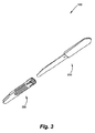
図3は、安全メス100を組立てる前のハンドル200およびカートリッジアセンブリ300の背面方向からの斜視図を示す。
FIG. 2 is a front perspective view of the
FIG. 3 shows a perspective view from the rear side of the
図4〜図6は、組立て後の安全メス100を示す。図4は、刃がシールド400内の後退位置にある安全メス100の正面方向からの斜視図である。図5は、刃600がシールド400の外で延出位置にある安全メス100の正面方向からの斜視図である。図6は、刃600が後退位置にある安全メス100の背面方向からの斜視図である。
4 to 6 show the
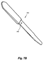
図1および図7A〜7Cに示すように、安全メス100のハンドル200は、第1の端部202および第2の端部204を備える。ハンドル200は、一般に、保持部210、ロック部220、および係合部230である3つの部分を含む。保持部210は、第1の端部202からロック部220まで延在する。係合部230は、第2の端部204からロック部220まで延在する。
As shown in FIG. 1 and FIGS. 7A to 7C, the
ハンドル200の保持部210は、印を含むことができる。安全メス100のユーザが、使用時に測定を行う、または、長さを計算することが望ましい場合がある。目盛り212などの印は、ハンドル200の保持部の少なくとも1つの面に印刷またはエッチングすることができる。多くの実施形態では、目盛り212は、インチ単位、センチメートル単位、ミリメートル単位などとすることができる。
The holding
ハンドル200のロック部220は、カートリッジアセンブリ300の端部と係合することができる。以下で詳細に述べるように、ロック部220は、シールド400の端部と係合し、ハンドル200に対するカートリッジアセンブリ300のぐらつきを、なくさない場合には、低減するために、シールド400と嵌合するキー溝を付けられる。
The locking
ハンドルの係合部230は、カートリッジアセンブリ300の中空キャビティ内に受容されるように構成されている。係合部230は、係合部230の対向する面のそれぞれに沿う突出傾斜部232、画定された切欠き234、スライダ500の一部を受容するように構成されたキー溝236、ぐらつき防止デテントまたは突起238、およびカートリッジアセンブリ300をハンドル200にロックするためにシールド400からタブ410を受容するように構成された孔240を含む。突起238は、スライダ500と係合して、安全メス100が作動位置で作動するときに第1の方向へのぐらつきを防止する一方で、ハンドル200のキー溝236は、スライダ500の延出部材502(図11Bに示す)と共働して第2の方向へのぐらつきを防止する。
The
図8Aは、刃600が後退位置にあるカートリッジアセンブリ300の正面方向からの斜視図である。図8Bは、刃が延出位置にあるカートリッジアセンブリの正面方向からの斜視図である。図8Aおよび図8Bに示すように、カートリッジアセンブリ300は、シールドまたは刃ガード400、シールドまたは刃ガード400のキャビティ402内に摺動可能に取付けられるスライダまたは刃ホルダ500、刃600、およびボタン700または作動部材700を有する。図9は、カートリッジアセンブリ300の背面方向からの斜視図である。
FIG. 8A is a front perspective view of the
図1〜6ならびに図8A、図8B、図9、図10A〜10D、および図11に示すように、カートリッジアセンブリ300のシールド400は、長尺状をなすことができ、略矩形の断面を有する。図10Aを参照すると、シールド400は、実質的に中空であり、キャビティ402を画定し、ハンドル200の第2の端部204上を摺動し、実質的に係合部230まで覆うように構成されている。スライダ500は、シールド400によって画定されたキャビティ402内に配設されうる。いくつかの実施形態では、スライダ500は、シールド400のキャビティ402内に配置されたレール415に沿って摺動することができる。
As shown in FIGS. 1-6 and FIGS. 8A, 8B, 9, 10A-10D, and 11, the
シールド400は、ハンドルのロック部220と係合するように構成された第1の端部404から第2の端部406まで延在する。例示的な実施形態では、第1の端部404はハンドル係合端であり、第2の端部406は刃係合端である。
The
カートリッジアセンブリ300が使用中にハンドル200から滑り落ちることおよび/またはハンドル200に対して相対移動することを防止するために、カートリッジアセンブリ300は、ハンドル200の係合部230上に取付けられると、ハンドル200に対して所定位置にロックすることができる。カートリッジアセンブリ300のシールド400は、シールド400の第2の面上に配置されうるロックスナップ410を備えることができる。ロックスナップまたはタブ410は、ハンドル200の係合部上の孔240と係合して、カートリッジアセンブリ300がハンドル200に取付けられた後にハンドル200から滑り落ちることを防止する。換言すれば、孔240は、ロックスナップ410を受容することができる。
To prevent the
カートリッジアセンブリ300がハンドル200から外れることが誤って起こりうる多くの従来技術の解決策と違い、本発明の安全メス100は、カートリッジアセンブリ300の偶発的な脱離を防止する。多くの実施形態では、カートリッジアセンブリ300は使い捨て式とすることができる。カートリッジアセンブリ300を廃棄することが所望される場合には、従事者は、カートリッジアセンブリ300をハンドル200から取外す。カートリッジアセンブリ300を取外すために、従事者は、鉗子、プライヤ、または別の同様の器具を用いることを必要とする場合がある。器具の先は、ハンドル200の孔240からシールド400のロックスナップ410を持上げることができる。従来の設計は、ハンドル200からのカートリッジアセンブリ300の分解を可能にするが、メスの使用中の脱離の可能性を含む安全を脅かす結果を伴う。安全メス100は、ハンドル200からのカートリッジアセンブリ300の偶発的な脱離を防止する。その理由は、カートリッジアセンブリ300の脱離が、孔240からロックスナップ410を持上げるという積極的な行為を必要とするためである。
Unlike many prior art solutions where the
もう一度シールド400を参照すると、シールド400は、第1の面に沿って長手方向に延在するスロット420を有することができる。スロット420は、シールド400の第1の端部404の近傍のスライダ非係合端422から第2の端部406の近傍のスライダ係合端424まで延在する。他の所で述べるように、スライダ500は、さらに、ボタン700を担持することができる。ボタン700は、スロット420に沿って第1の端部(スライダ非係合端422)から第2の端部(スライダ係合端424)まで、また、その逆に移動させられうる。ボタン700は、ステム702によりスライダ500に取り付けることができる。ボタン700のヘッド704は、シールド400の外に配設されることができる一方で、スライダ500はシールド400内に留まる。
Referring once again to the
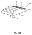
シールド400の少なくとも1つの面は、グリップ430を備えることができる。グリップ430は、シールド400のある面の表面に沿って画定された複数のU字状切欠きを備えることができる。図面に示すように、グリップ430は、2つ以上の面/表面上に配置されてもよい。
At least one surface of the
さらに、位置インジケータまたは延出部材440は、シールド400の少なくとも1つの面から延在することができる。安全メス100が使用されているとき、位置インジケータ440は、位置を特定するために、または滑りを防止すべく触知グリップを提供するために使用されうる従来のメス上のハンドルと刃との間の移行段差を真似ることによって、視覚と感触/触覚の両方によってメス100の位置を即座に示す。これは、切開されている表面において刃600がどれだけ深くにあるかを判定する際に、または、刃が存在する場所についての感触を有するのに役立ち、使用中の滑りを防止するための機械的利点を提供しうる。たとえば、位置インジケータ440は、患者の表皮または組織内に外科医がどれほど深くまで切開したかを即座に示す。
Further, the position indicator or
図1および図11A〜11Bに全体的に示されるスライダ500は、ハンドル200およびシールド400と摺動可能に係合することができる。スライダ500がシールド400およびハンドル200に対して摺動するにつれて、スライダ500および刃600は、シールド400内から延出することができ、また、シールド400内に後退して戻ることができる。外科医または医療専門家などのユーザは、ボタン700をスライダ非係合端422からスライダ係合端424へ移動させることによってシールド400内から刃600を延出させることができる。ユーザは、ボタン700をスライダ係合端424からスライダ非係合端422へ移動させて戻すことによって刃600をシールド300内に後退させて戻すことができる。
The
安全メス100は、刃600がシールド400内の後退位置にある状態で保管することができる。この位置では、刃600は、完全にシールド400内にあり、刃600の先602も、鋭利な切刃604も露出されない。
The
メス100の取扱いは、偶発的な切開が回避されうるため、刃600が後退位置にあると、より安全である。特に、看護師または手術室要員である技師が外科医にメス100を渡す手順は、刃600の切刃が露出されず、外科医も看護師も傷つけることができないため、実質的により安全にされる。
Handling the
安全性を高めるために、スライダ500は、シールド400内でロックされてもよく、カートリッジアセンブリ300がハンドル200上に取付けられていないときに、刃600がハウジング300内から延出することを防止することができる。
To increase safety, the
図1〜2、図4〜5、および図7A〜7Cは、メスハンドル200の例示的な実施形態の正面方向からの斜視図を示す。メスハンドル200は、長手方向軸201、ユーザが把持するための保持部210、および刃カートリッジ300を受容するための係合部230を備えることができる。例示的な実施形態では、係合部230は、メスハンドル200の長さの約半分を含み、保持部210は残りの半分を含む。保持部210と係合部230との間には、シールド400の第1の端部402と共働して嵌合するような寸法及び形状を有するロック部220が設けられる。
1-2, 4-5, and 7A-7C show perspective views from the front of an exemplary embodiment of a
ハンドル200の係合部230は、カートリッジアセンブリ300に嵌入できるように、保持部210より細く、かつ実質的に薄くすることができる。好ましくは、係合部230は、保護用刃ハウジング300への挿入および安全メス100の組立ての改善のためにテーパ付き先端242を備えることができる。
The engaging
長手方向溝またはキー溝236は、ハンドル200の係合部230に沿って配設されて、刃デテント504およびヒートステークを介してスライダ500へ刃600を取付けた後に、スライダ500の延出部材502を収容し、受容してもよい。
A longitudinal groove or
ハンドル200はまた、ハンドルの係合部230に配置されるぐらつき防止デテント238を備えることができる。いくつかの実施形態では突起または外側に延在する部材であるぐらつき防止デテント238は、ハンドル200から上に延在し、カートリッジアセンブリ300がハンドル200上に配置されると、スライダ500と係合する。ぐらつき防止デテント238は、刃600がカートリッジアセンブリ300から延出し、使用状態にあるときに、スライダ500のボタンを押して刃600を安定化させることができる。
The
安全メス100の使用中に指と接触したときのメスハンドル200の摩擦力を増大させるために、ハンドル部210は、ハンドル200の前部および/または後部上に配置された複数の溝を含んでいてもよい。複数の溝は、使用中における安全メス100の滑りを防止することができる。
In order to increase the frictional force of the scalpel handle 200 when in contact with a finger during use of the
図面に示すように、メスハンドル200の保持部230は、印212を含むことができる。印212は、一般的に、メスハンドル200の前面に位置しうる。印212は、複数のマークまたは印刷を含むことができ、印212は、好ましくは、限定はしないが、メートル法、ヤードポンド法、または多くの他の適切な測定系などの測定単位である。
As shown in the drawings, the
ハンドル200は、カートリッジアセンブリ300を受容し、使用時に従来のメスの感触をユーザに提供するように設計される。そのため、ユーザが快適に使用するための材料、重量、および設計が提供されうる。いくつかの実施形態では、ハンドル200および刃600は、ステンレス鋼で形成することができ、一方で、シールド400、スライダ500、およびボタン700は、ポリカーボネート材料で形成される。
The
図1〜6および図8A〜10Dは、シールド400の斜視図を示す。シールド400は、長手方向軸を備えることができ、略矩形の断面を有した長尺状とすることができる。シールド400は中空であり、第1の端部404に第1の開口407と、第2の端部406に第2の開口409とを有するキャビティ402を画定する。
1-6 and FIGS. 8A-10D show perspective views of the
シールド400は、前側壁に広がるスロット420を備えることができる。スロット420は、長尺状をなすことができ、メス100の軸201と略平行に配向されうる。スロット420は、スロット420の端部に開口422および424、すなわちスライダ非係合端部422およびスライダ係合端424を備えることができる。スロット422および424は、スライダを設定位置に維持するための延長部425を有することができる。
The
スライダ500は、シールド400内に挿入され収容されることができる。ボタン700のステム702は、スライダ500のステム受容孔506に通されることができ、一方で、ヘッド704はシールド400の外に留まる。ステム受容孔506は、ボタン700のステム702を収容できるだけの幅を有する。ユーザは、最初にボタン700を(シールド500に向かって)押下げ、所望の方向に該ボタン700を押すまたは引張ることによって、シールド400内でスライダ500を移動させることができる。スライダ500が移動するとき、スロット420は、ボタン700のステム702の移動を制限することによって、シールド400の長さ方向と実質的に平行な長手方向を除いて、スライダ500が任意の方向に移動することを防止する。ステム702がスロット420の範囲内でしか移動できないため、スロット420はまた、スライダ500が移動できる総距離を制限する。いくつかの実施形態では、ボタン700のヘッド704は、ボタン700と係合するときにより良好な把持力をユーザに提供するために、その表面上に複数の隆起705を有することができる。
The
上述したように、安全メス100は、刃600を延出する/後退させるように構成される。たとえば、この珍しくない/直観的な行為は、従来のボックスカッターデバイスを使用する場合に似ている。ユーザが、刃を露出させるためにシールドを後方に摺動させ、また、意識的に刃を覆うために、より一層ぎこちなくシールドを前方に摺動させなければならない、従来の一部のメスとは対照的に、本安全メス100は、ボタン700を下に押してシールド400に沿ってボタン700を長手方向に摺動させることによって刃600を延出させ、また後退させるように構成されている。
As described above,
シールド400は、シールド400の第1の開口407内にハンドル200の係合部230を挿入することによって、メスハンドル200に取付けることができる。シールド400は、シールド400の端部がハンドル200のロック部220の壁に当接し、ロックスナップ410が孔240と係合するまで、係合部230に沿って摺動できる。
The
シールド400は、孔240からロックスナップ410を持上げることによってハンドルから脱離されることができる。これは、鉗子、ロングノーズプライヤ、または他の同様な器具のセットの使用を必要とする場合がある。ロックスナップ410が孔240から取外されると、シールド400、およびより一般的にはカートリッジアセンブリ300は、ハンドル200の保持部210から離れるようにシールド400を引張ることによって取外すことができる。
The
スライダ係合端424は、スライダ500を延出位置にロックすることを容易にしうる。この端部は、スライダ500を延出位置に固定し、対象物に対してメスを押すことによって生成される第1の端部404の方向への力が、スライダまたは刃ホルダ500を保護用刃ハウジング300内に押し戻すことを防止する。スライダ500は、スライダ係合端424とスライダ500との係合を解除するためにボタン700を押し、第1の端部404の方向にボタン700を引張ることによって、後退させることができる。
The
さらなる安全性のために、スライダ500は、カートリッジアセンブリ300がハンドル上に取付けられていないときに、シールド400内でロックされて、刃600の偶発的な延出を防止してもよい。図1に示すように、シールド400は、第1の端部404の近傍に位置するスライダロック孔450を備えることができる。スライダ500は、一方、一対の脚部−少なくとも1つの前脚部510および少なくとも1つの後脚部520−を備える。後脚部520は、一対の前足部522および524ならびに一対の後足部526および528を備えることができる。ばね仕掛けとすることができる後足部526および528は、1つまたは複数の穴を備えることができるロック孔450内に受容されることができる。図面に示すように、ロック孔450は、2つの別個の異なる孔を含むことができ、各孔は、後足部526または528の少なくとも一方を受容する。シールド400の後足部526および528は、シールド400のロック孔内でロックされるため、刃600も担持するスライダ500は、シールド400から延出するように移動できず、したがって、一旦組立てられると、ユーザを偶発的に傷つけたり怪我を負わせたりすることができない。
For added safety, the
上述したように、カートリッジアセンブリ300が完全に組立てられると、刃600は、シールド400から偶発的に延出できない。完全に組立てられたカートリッジアセンブリ300は、スライダ500によって担持された刃600を備える。図12を参照すると、刃600は、刃先602、切刃604、およびスライダ孔606を有する。スライダ500の延出部材504は、刃600のスライダ孔606と係合することができ、したがって、スライダ孔606によって受容されうる。スライダ孔606および延出部材504は、共働して嵌合するようにキー溝が付けられている。スライダ500は、その後、シールド400のキャビティ402内に配置可能である。刃600を担持するスライダ500は、シールド400の第2の端部406の第2の開口409に挿入することができる。
As described above, the
ここで、ボタン700は、スライダ500に連結することができる。図13Aおよび図13Bを参照すると、ボタン700は、第1の表面706および第2の表面707を有するヘッド704を有する。ヘッド704は、第1の表面706から延在するステム702を有することができる。ヘッド704はまた、第2の表面707上に複数の隆起705を備えることができる。ステム702は、スライダ500のステム受容孔506に挿入することができる。いくつかの実施形態では、ステム702をスライダ500にヒートステークすることが望ましい場合がある。こうした実施形態では、ヒートステーク穴455が、スロット420に対向するシールド400の面上に配置される。必要とされる熱が、ヒートステーク穴455を介して加えられて、ボタンのステム702がスライダ500に結合されうる。ボタン700は、スライダ500がシールド400の第1の端部404近傍にロックされるように、スロット420に沿って摺動させることができる。この位置で、後脚部520は、シールド400のロック孔450に受容されうる。スライダ500は、その後足部526および528をシールド400の孔450と係合させることによってシールド400内にロックすることができる。結果として、スライダ500はハンドル200上に配置されなければ移動できず、刃600はシールド400から延出しない。
Here, the
カートリッジアセンブリ300がハンドル200に連結されると、スライダ500は、刃600が使用されうる延出または係合位置と、刃600が収容される非係合または固定位置との間で移動することができる。
When the
上述したように、カートリッジアセンブリ300は、ハンドル200の係合部230に固定することができる。ハンドル200の第2の端部204は、シールド400の第1の端部404の第1の開口407に挿入することができる。ハンドル200は、係合部230の対向する面に沿って一対の傾斜部232を備える。スライダ500の延出部材502は、係合部230のキー溝236に嵌入するような寸法とされる。カートリッジアセンブリ300がハンドル200の係合部230を受容すると、延出部材502がキー溝236と係合し、後脚部520が傾斜部232に沿って摺動する。孔240と係合するロックスナップ410を備えるカートリッジアセンブリ300がハンドルに固定されると、シールドの第1の端部404は、ハンドル200のロック部220を受容する。ロック部220は、シールド400の第1の端部404の第1の開口407の一部に挿入可能である。たとえば、第1の開口407は、ロック部220と共働して係合するために、面取りされた角を有することができる。カートリッジアセンブリ300がハンドルの係合部230に沿って摺動するにつれて、スライダ500の後脚部520は、傾斜部232に沿って摺動する。これにより、後脚部520が持上げられ、シールド400のロック孔450から外れる。その結果、ボタン700が押下されると、スライダ500がシールド400内で摺動することができ、ボタン700が、シールド400のスロット420に沿って摺動して、最終的に刃600を露出させて延出させることができる。
As described above, the
ボタン700が押下されると、スライダ500の底の一部分は、ハンドルの係合部230のU字状切欠き234内に落ち込むことができる。切欠き234は、スライダ500がハンドル200の係合部230に沿って移動することを可能にするために、スライダ500の必要な部分を受容できる寸法及び形状とされる。
When the
シールド400の第2の端部近傍の第2の開口409は、刃600を延出させる方向にユーザがボタン700を移動させるときに、シールド400の外側の方向にスライダ500が刃600を延出させることを可能にするように構成することができる。
The
いくつかの実施形態では、刃600は、スライダ500にヒートステークされてもよい。すなわち、刃600は、熱を加えることによってスライダ500に固定されることができ、これにより、刃600を所定位置に確実にロックする。
In some embodiments, the
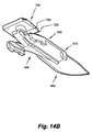
図14Aおよび図14Bは、刃600が取付けられたスライダ500の例示的な実施形態の斜視図を示す。当業者であれば、刃600は、限定はしないが、炭素とステンレス鋼の両方を含む種々の好適な材料で作られうることが認識されるであろう。一般に、刃600を形成するために使用される炭素およびステンレス鋼は、英国規格(「BS」)2982:1992、国際標準化機構(「ISO」)7740:1985、および欧州規格(「EN」)27740:1992を含むいくつかの工業規格に準拠して製造される。刃600は、さらに、たとえばガンマ線照射によって減菌することができる。
14A and 14B show perspective views of an exemplary embodiment of a
図1〜6、図8A〜9、および図15A〜15Bは、カートリッジアセンブリ300の例示的な実施形態の斜視図を示す。述べたように、カートリッジアセンブリ300は、シールド400、スライダ500、および刃600を備えることができる。カートリッジアセンブリ300は、ハンドル200に取付けることができ、廃棄および/または交換のために容易に取外すことができる。カートリッジアセンブリ300は、第2の端部204を第1の開口407に挿入することによって、メスハンドル200の係合部230に確実に外嵌することができる。ロックスナップ410は、カートリッジアセンブリ300をハンドル200上に固定するために孔240と係合することができ、使用中にカートリッジ300がハンドル200から滑り落ちることを防止する。
1-6, 8A-9, and 15A-15B show perspective views of an exemplary embodiment of the
スライダ500は、メスハンドル200の係合部230とシールド400の前側壁との間において、シールド400内に配設することができる。スライダ500は、ユーザがボタン700を移動させるにつれて、係合部230上を摺動することができる。
The
スライダ500は、ボタン700を押下しシールド400の第1の端部404に向かって引張ることによって、ロック位置から後退させることができる。メス100は、スライダ500が完全に後退させられた状態で保管され、取り扱われるように設計される。この位置では、刃600は、シールド400によって完全に覆われ、メス100は、刃600の鋭利な切刃が露出しないため、取り扱うのに安全である。
The
カートリッジアセンブリ300は、スライダ500が後退位置にあるときに、ハンドル200から取外すことができる。これは、孔240からロックスナップ410を取外すことを伴う。
The
図15Aは、ハンドル200を挿入する前のカートリッジアセンブリ300の斜視図である。特に、バネ仕掛けの後足部526、528は、ハンドル200を挿入しない状態で刃600の延出を防止するように構成される。具体的には、後足部526、528は、シールドの第1の端部404近傍に位置するスライダロック孔450内でロックされる。こうして、刃600を有するスライダ500は、シールド400内でロックされて、ハンドルを取付けていない状態で刃600が偶発的にシールドから延出することを防止する。図15Bに示すように、スライダをロック解除するために、後足部526、528は、ハンドル200を挿入することによって、持上げられるか上昇させられて孔450から外れることができる。具体的には、ハンドル200を挿入することによって、傾斜部232はそれぞれ、各足部526、528を持上げる。ハンドル200がカートリッジアセンブリ300に挿入されると、シールド400のロックスナップ410は、ハンドル200の係合部上の孔240と係合して、カートリッジアセンブリ300が、ハンドル200に取付けられた後にハンドル200から滑り落ちることを防止する。換言すれば、孔240は、ロックスナップ410を受容することができる。カートリッジアセンブリ300は、両手と外部器具によって、たとえば外部器具を使用して孔240からロックスナップ410を持上げることによって、ハンドル200から脱離されうる。たとえば、ロックスナップ410は、ハンドル200からカートリッジアセンブリ300を脱離させるように、スナップロックまたはロックスナップのロックを解除するのに適した解除ツールによって、孔240から持上げられてもよい。解除ツールはピンセットであってもよい。カートリッジアセンブリ300を脱離させるために外部器具を用いるのみでよいということの利点は、作動位置にあるときに不注意に手が動く間、または、安全メス100の操作中に、ハンドル200からのカートリッジアセンブリ300の偶発的な脱離を防止することである。カートリッジアセンブリ300を脱離させるために両手を必要とする、すなわちメス100を保持するために一方の手を、ロックスナップ410を孔240から持上げる外部器具を使用するためにもう一方の手を必要とすることによって、カートリッジアセンブリ300の偶発的な脱離のリスクが低減されうる。
FIG. 15A is a perspective view of the
さらに、全ての上記実施形態において、ハンドル200、特に、ハンドル200の保持部210などの把持表面は、手と把持表面との間の摩擦力を向上させうるゴム材料などの防滑材料で形成されるかあるいはコーティングされてもよい。たとえば、保持部210は、合成ゴム材料でコーティングすることができる。ハンドル200は、金属材料で形成することができる。刃ガード、刃ホルダ、および作動部材は、たとえばポリカーボネート材料などの熱可塑性材料などのプラスチックで形成することができるが、材料はこれに限定されるものではない。
Furthermore, in all the above embodiments, the
上記から、本発明が多数の切断デバイスを提供することがわかる。上述した本発明の種々の実施形態は、切断部を保持するためのハンドルおよび使い捨て式カートリッジアセンブリを有する安全メスを提供する。 From the above, it can be seen that the present invention provides a number of cutting devices. The various embodiments of the present invention described above provide a safety scalpel having a handle for holding a cut and a disposable cartridge assembly.
本発明の実施形態は、本発明の趣旨または本質的な特徴から逸脱することなく、他の特定の形態で実施されうる。たとえば、本発明の実施形態は、外科医が使用するための安全メスの文脈で述べられたが、本明細書で述べる概念は、これらの例証的な実施形態に限定されない。 Embodiments of the invention may be implemented in other specific forms without departing from the spirit or essential characteristics of the invention. For example, although the embodiments of the present invention have been described in the context of a safety scalpel for use by a surgeon, the concepts described herein are not limited to these illustrative embodiments.
上記実施形態は、添付の図面と共に詳細に述べられたが、これらの実施形態からの種々の変更が、本発明の範囲から逸脱することなく行われうることが理解されるであろう。 Although the above embodiments have been described in detail in conjunction with the accompanying drawings, it will be understood that various modifications from these embodiments can be made without departing from the scope of the invention.
Claims (18)
前記長手方向軸に平行に、または該長手方向軸に沿って、前記ハンドルの少なくとも一部分上に着脱可能にかつ摺動可能に取付けられたカートリッジアセンブリであって、
第1の端部および第2の端部ならびに前記第1の端部近傍に画定されたロック孔を有し、中空のキャビティを画定し、前記ハンドルの前記第2の端部上に摺動可能に取付けられる、刃ガード、
前記刃ガードの前記キャビティ内に摺動可能に取付けられ、少なくとも1つの前脚部および少なくとも1つの後脚部を有する、刃ホルダであって、前記少なくとも1つの後脚部は、一対の前足部および一対の後足部を有し、前記一対の後足部は、バネ仕掛けとすることができ、前記刃ガードの前記ロック孔内に受容されることができる、刃ホルダ、および、
前記刃ホルダが前記刃ガードの前記キャビティ内で摺動すると、前記刃が、前記刃ガードの前記第2の端部から延出するか、または前記第2の端部内に後退するように、前記刃ホルダと共働して嵌合するようにキー溝を付けられた刃
を備える、カートリッジアセンブリと
を備える安全メス。 A handle having a first end and a second end and having a longitudinal axis extending between the first end and the second end;
A cartridge assembly detachably and slidably mounted on at least a portion of the handle parallel to or along the longitudinal axis ;
Having a first end and a second end and said first end lock hole defined near, defining a middle empty cavity, sliding on said second end of said handle Mounted as possible, blade guard,
A blade holder slidably mounted in the cavity of the blade guard and having at least one front leg and at least one rear leg, the at least one rear leg comprising a pair of front legs and a pair of rear foot portion, the pair of rear foot portion may be a spring-loaded, can be received in the locking hole of the blade guard, blade holder and,
As the blade holder slides within the cavity of the blade guard, the blade extends from the second end of the blade guard or retracts into the second end. A safety knife comprising a cartridge assembly comprising a blade keyed to mate and engage with a blade holder.
前記第1の端部から、前記第1の端部と前記第2の端部との間に配置されたロック部まで延在する保持部、および、
前記第2の端部から前記ロック部まで延在する係合部
を備え、
前記カートリッジアセンブリが、前記長手方向軸に平行に、前記ハンドルの前記係合部上に着脱可能にかつ摺動可能に取付けられ、
前記刃ガードが前記ハンドルの前記第2の端部上に摺動可能に取付けられて、前記係合部を覆い、刃ガードの前記第1の端部が前記ロック部と係合し、
前記カートリッジアセンブリはさらに、前記刃ホルダに取付けられた作動部材であって、前記刃ガードの前記第2の端部の外側の延出位置と前記刃ガードの前記第2の端部内の後退位置との間で前記刃の一部分を移動させるように前記刃ホルダを作動させるように構成された作動部材を備える、請求項1に記載の安全メス。 The handle further comprises :
A holding portion extending from the first end portion to a lock portion disposed between the first end portion and the second end portion; and
An engagement portion extending from the second end portion to the lock portion ;
The cartridge assembly, the flat row in the longitudinal axis, removably and slidably mounted on said engaging portion of said handle,
The blade guard is slidably mounted on said second end of said handle, covering the engagement portion, the first end of the blade guard is engaged with the locking portion,
The cartridge assembly is further an actuating member attached to the blade holder , wherein the cartridge guard extends outward from the second end of the blade guard and a retracted position within the second end of the blade guard. The safety knife of claim 1 , comprising an actuating member configured to actuate the blade holder to move a portion of the blade between.
Applications Claiming Priority (3)
| Application Number | Priority Date | Filing Date | Title |
|---|---|---|---|
| US35924910P | 2010-06-28 | 2010-06-28 | |
| US61/359,249 | 2010-06-28 | ||
| PCT/SG2011/000228 WO2012002910A1 (en) | 2010-06-28 | 2011-06-28 | Safety scalpel |
Publications (3)
| Publication Number | Publication Date |
|---|---|
| JP2013530009A JP2013530009A (en) | 2013-07-25 |
| JP2013530009A5 JP2013530009A5 (en) | 2014-06-26 |
| JP5613325B2 true JP5613325B2 (en) | 2014-10-22 |
Family
ID=45402374
Family Applications (1)
| Application Number | Title | Priority Date | Filing Date |
|---|---|---|---|
| JP2013518340A Active JP5613325B2 (en) | 2010-06-28 | 2011-06-28 | Safety knife |
Country Status (13)
| Country | Link |
|---|---|
| US (1) | US8567072B2 (en) |
| EP (1) | EP2584981B1 (en) |
| JP (1) | JP5613325B2 (en) |
| KR (1) | KR101852007B1 (en) |
| CN (1) | CN103079484B (en) |
| AU (1) | AU2011271744B2 (en) |
| CA (1) | CA2800645C (en) |
| ES (1) | ES2543917T3 (en) |
| MX (1) | MX2012014155A (en) |
| MY (1) | MY159138A (en) |
| SG (1) | SG184982A1 (en) |
| TW (1) | TWI461175B (en) |
| WO (1) | WO2012002910A1 (en) |
Families Citing this family (32)
| Publication number | Priority date | Publication date | Assignee | Title |
|---|---|---|---|---|
| CA2763501C (en) * | 2009-05-26 | 2015-11-03 | Southmedic Incorporated | Blade unit for surgical scalpel |
| US9247954B2 (en) * | 2010-04-21 | 2016-02-02 | Ravi Nallakrishnan Revocable Trust | Safety knife with retractable and extendable blade and guard |
| GB2487950A (en) * | 2011-02-10 | 2012-08-15 | Samuel George | Cutting implement with protective sheath |
| AU2012311160B2 (en) * | 2011-09-23 | 2015-11-19 | Medi- Safe Surgicals (Pty) Ltd | Scalpel Blade Accessory |
| US9808373B2 (en) | 2013-06-28 | 2017-11-07 | Aquesys, Inc. | Intraocular shunt implantation |
| US9622773B2 (en) | 2012-03-19 | 2017-04-18 | Aspen Surgical Products, Inc. | Side activated safety scalpel for left and right hand users with blade removal system |
| EP3068354B1 (en) | 2013-11-14 | 2023-06-28 | Aquesys, Inc. | Intraocular shunt inserter |
| CN103565496A (en) * | 2013-11-25 | 2014-02-12 | 王红军 | Tissue cutter |
| WO2015134601A1 (en) * | 2014-03-05 | 2015-09-11 | Spectra Medical Devices, Inc. | Safety scalpel |
| EP2915495B1 (en) * | 2014-03-07 | 2016-10-05 | Aspen Surgical Products, Inc. | Scalpel handle sheath with blade remover |
| JP6406661B2 (en) * | 2014-06-12 | 2018-10-17 | 株式会社貝印刃物開発センター | Medical knife and manufacturing method thereof |
| US20160095614A1 (en) | 2014-10-03 | 2016-04-07 | Aspen Surgical Products, Inc. | Sharps blade applicator and storage device |
| US10123815B2 (en) | 2015-02-13 | 2018-11-13 | Precision Engineered Products, Llc | Surgical knife |
| US10092314B2 (en) * | 2015-02-27 | 2018-10-09 | Medipurpose Pte Ltd | Safety scalpel with replaceable blade cartridge |
| USD800905S1 (en) | 2015-03-06 | 2017-10-24 | Aspen Surgical Products, Inc. | Scalpel handle sheath |
| CN105125260A (en) * | 2015-08-19 | 2015-12-09 | 扬州永安塑业有限公司 | Disposable safety scalpel |
| USD813390S1 (en) | 2016-01-15 | 2018-03-20 | Aspen Surgical Products, Inc. | Surgical scalpel blade attachment |
| US20170265882A1 (en) | 2016-03-21 | 2017-09-21 | Aspen Surgical Products, Inc. | Safety scalpel handle |
| US20180028214A1 (en) * | 2016-07-29 | 2018-02-01 | Friedman Medical Instruments, LLC | Tensioned collet scalpel handle |
| WO2018030954A1 (en) * | 2016-08-12 | 2018-02-15 | Medipurpose Pte Ltd. | Safety scalpel with replaceable blade cartridge |
| CN107184251B (en) * | 2017-07-17 | 2023-04-21 | 安徽赢创医疗科技有限公司 | Disposable safety multipurpose surgical knife |
| USD831826S1 (en) | 2017-09-05 | 2018-10-23 | Aspen Surgical Products, Inc. | Surgical blade loader |
| US11370132B2 (en) * | 2018-01-10 | 2022-06-28 | Havel's, Llc | Interchangeable cutlery system |
| US10952898B2 (en) * | 2018-03-09 | 2021-03-23 | Aquesys, Inc. | Intraocular shunt inserter |
| CN109247975A (en) * | 2018-07-19 | 2019-01-22 | 卢加贵 | Laparoscope micro-wound surgical operation knife |
| US20200390463A1 (en) * | 2019-06-14 | 2020-12-17 | Quadvantage Technology, Inc. | Dual-blade tendon cutting apparatus and cartridge for multiple apparatuses |
| US11376022B2 (en) | 2019-07-18 | 2022-07-05 | Quadvantage Technology, Inc. | Patella cutting guide |
| KR20210020560A (en) | 2019-08-16 | 2021-02-24 | 주식회사 덴탈스튜디오 | Medical scalpel |
| CN110547881A (en) * | 2019-10-14 | 2019-12-10 | 深圳市鑫劲丰硅橡胶有限公司 | Medical grade surgical instruments protection silica gel circle |
| KR102494436B1 (en) | 2020-08-19 | 2023-01-31 | 인제대학교 산학협력단 | Medical scalpel unit |
| KR102313016B1 (en) * | 2021-07-23 | 2021-10-14 | 주식회사 덴탈스튜디오 | Medical Scalpel Holder with Easy Blade Removal |
| SI26313A (en) * | 2022-02-21 | 2023-08-31 | RaMax Engineering, d.o.o. | Scalpel for eye surgery with protection |
Family Cites Families (36)
| Publication number | Priority date | Publication date | Assignee | Title |
|---|---|---|---|---|
| US5299357A (en) | 1991-12-18 | 1994-04-05 | American Safety Razor Company | Disposable surgical scalpel with safety guard |
| US5309641A (en) * | 1991-12-18 | 1994-05-10 | American Safety Razor Company | Disposable surgical scalpel with safety guard |
| US5411512A (en) * | 1992-01-24 | 1995-05-02 | Leonard Bloom | Guarded surgical scalpel |
| US5496340A (en) * | 1992-01-24 | 1996-03-05 | Leonard Bloom | Combination guarded surgical scalpel and blade stripper |
| US5330493A (en) * | 1992-11-27 | 1994-07-19 | Haining Michael L | Disposable scalpel |
| US5342379A (en) | 1993-06-01 | 1994-08-30 | Volinsky Fredric G | Safety scalpel |
| US5941892A (en) * | 1993-12-08 | 1999-08-24 | Becton, Dickinson And Company | Surgical scalpel |
| US5938676A (en) * | 1993-12-08 | 1999-08-17 | Becton, Dickinson & Company | Surgical scalpel |
| US6053929A (en) * | 1993-12-08 | 2000-04-25 | Becton Dickinson And Company | Surgical scalpel |
| US5919201A (en) * | 1993-12-08 | 1999-07-06 | Becton, Dickinson And Company | Surgical scalpel |
| US5571127A (en) * | 1995-03-08 | 1996-11-05 | Decampli; William M. | Scalpel handle having retractable blade support and method of use |
| US5683407A (en) * | 1995-10-19 | 1997-11-04 | Becton, Dickinson And Company | Cleanable guarded surgical scalpel with scalpel blade remover |
| IT1276991B1 (en) * | 1995-10-24 | 1997-11-03 | Giuseppe Pilo | DISPOSABLE SURGICAL SCALPEL FOR SAFETY |
| US5924206A (en) * | 1997-09-30 | 1999-07-20 | Becton, Dickinson And Company | Reusable device handle |
| US5908432A (en) * | 1998-03-27 | 1999-06-01 | Pan; Huai C. | Scalpel with retractable blade |
| ITSS20000003A1 (en) * | 2000-05-10 | 2001-11-10 | Giuseppe Pilo | SAFE DISPOSABLE SURGICAL SCALPEL |
| US6254621B1 (en) * | 2000-06-01 | 2001-07-03 | S & S Surgical Products, Inc. | Closed channel retractable surgical blade device and associated method |
| US6757977B2 (en) * | 2001-11-20 | 2004-07-06 | Jai Surgicals Limited | Disposable surgical safety scalpel |
| US6884240B1 (en) * | 2001-12-07 | 2005-04-26 | Ronald Dykes | Protection system for surgical instruments |
| JP4865189B2 (en) * | 2002-02-21 | 2012-02-01 | 古河電気工業株式会社 | GaN-based field effect transistor |
| JP4072380B2 (en) * | 2002-05-30 | 2008-04-09 | 株式会社貝印刃物開発センター | Surgical knife |
| BR0314456A (en) * | 2002-09-20 | 2005-07-26 | Occupational & Med Innovations | Safety Scalpel Blade Set |
| US7101382B2 (en) * | 2002-11-12 | 2006-09-05 | Samuel George | Retractable scalpel |
| US7207999B2 (en) * | 2004-03-12 | 2007-04-24 | Griffin Michael D | Safety scalpel |
| US7172611B2 (en) * | 2004-03-22 | 2007-02-06 | Becton, Dickinson And Company | Surgical scalpel assembly |
| US8015712B2 (en) | 2004-10-29 | 2011-09-13 | Medipurpose Pte Ltd | Safety scalpel |
| CN101094616B (en) * | 2004-10-29 | 2010-09-15 | 医用私人有限公司 | Safety scalpel |
| US20060212058A1 (en) * | 2005-03-18 | 2006-09-21 | Ilija Djordjevic | Disposable safety surgical blade |
| US20060241664A1 (en) * | 2005-04-25 | 2006-10-26 | Globe Medical Tech, Inc. | Automatic retractable blade scalpel |
| US7159713B1 (en) * | 2005-11-01 | 2007-01-09 | Georgene Austria | Sharp blade protection device |
| JP4486038B2 (en) * | 2005-12-15 | 2010-06-23 | 正一 中村 | Surgical scalpel blade holder |
| US20070255298A1 (en) * | 2006-05-01 | 2007-11-01 | Ilija Djordjevic | Disposable safety scalpel with reusable handle |
| US8464430B2 (en) * | 2008-02-07 | 2013-06-18 | Beaver-Visitec International (Us), Inc. | Retractable safety knife |
| US8205340B2 (en) * | 2008-07-26 | 2012-06-26 | Georgene Austria | Safety scalpel with blade retention |
| US8181352B1 (en) * | 2008-12-03 | 2012-05-22 | Shackelford Sr Howard L | Scalpel with removable blade assembly |
| US20120245610A1 (en) * | 2011-03-24 | 2012-09-27 | Southmedic Inc. | Retractable and removable blade unit for a scalpel |
-
2011
- 2011-06-28 WO PCT/SG2011/000228 patent/WO2012002910A1/en active Application Filing
- 2011-06-28 TW TW100122572A patent/TWI461175B/en active
- 2011-06-28 SG SG2012078317A patent/SG184982A1/en unknown
- 2011-06-28 JP JP2013518340A patent/JP5613325B2/en active Active
- 2011-06-28 EP EP11801260.8A patent/EP2584981B1/en active Active
- 2011-06-28 MY MYPI2012005272A patent/MY159138A/en unknown
- 2011-06-28 US US13/701,510 patent/US8567072B2/en active Active
- 2011-06-28 AU AU2011271744A patent/AU2011271744B2/en active Active
- 2011-06-28 ES ES11801260.8T patent/ES2543917T3/en active Active
- 2011-06-28 KR KR1020127033577A patent/KR101852007B1/en active IP Right Grant
- 2011-06-28 MX MX2012014155A patent/MX2012014155A/en active IP Right Grant
- 2011-06-28 CA CA2800645A patent/CA2800645C/en active Active
- 2011-06-28 CN CN201180026447.0A patent/CN103079484B/en active Active
Also Published As
| Publication number | Publication date |
|---|---|
| US8567072B2 (en) | 2013-10-29 |
| US20130158574A1 (en) | 2013-06-20 |
| CA2800645C (en) | 2018-02-13 |
| CA2800645A1 (en) | 2012-01-05 |
| JP2013530009A (en) | 2013-07-25 |
| ES2543917T3 (en) | 2015-08-25 |
| MX2012014155A (en) | 2013-02-27 |
| EP2584981A1 (en) | 2013-05-01 |
| KR20130103681A (en) | 2013-09-24 |
| AU2011271744A1 (en) | 2012-12-13 |
| MY159138A (en) | 2016-12-15 |
| TWI461175B (en) | 2014-11-21 |
| SG184982A1 (en) | 2012-11-29 |
| EP2584981A4 (en) | 2014-02-26 |
| TW201206389A (en) | 2012-02-16 |
| CN103079484A (en) | 2013-05-01 |
| WO2012002910A1 (en) | 2012-01-05 |
| CN103079484B (en) | 2015-04-08 |
| EP2584981B1 (en) | 2015-06-03 |
| AU2011271744B2 (en) | 2014-08-28 |
| KR101852007B1 (en) | 2018-04-26 |
Similar Documents
| Publication | Publication Date | Title |
|---|---|---|
| JP5613325B2 (en) | Safety knife | |
| US8015712B2 (en) | Safety scalpel | |
| CA2584865C (en) | Safety scalpel | |
| US20140142600A1 (en) | Retractable universal safety scalpel | |
| EP2732780B1 (en) | Retractable universal safety scalpel | |
| AU2013213686A1 (en) | Retractable Universal Safety Scalpel |
Legal Events
| Date | Code | Title | Description |
|---|---|---|---|
| A529 | Written submission of copy of amendment under article 34 pct |
Free format text: JAPANESE INTERMEDIATE CODE: A529 Effective date: 20121219 |
|
| A521 | Request for written amendment filed |
Free format text: JAPANESE INTERMEDIATE CODE: A523 Effective date: 20140501 |
|
| A621 | Written request for application examination |
Free format text: JAPANESE INTERMEDIATE CODE: A621 Effective date: 20140501 |
|
| A871 | Explanation of circumstances concerning accelerated examination |
Free format text: JAPANESE INTERMEDIATE CODE: A871 Effective date: 20140501 |
|
| A975 | Report on accelerated examination |
Free format text: JAPANESE INTERMEDIATE CODE: A971005 Effective date: 20140529 |
|
| A131 | Notification of reasons for refusal |
Free format text: JAPANESE INTERMEDIATE CODE: A131 Effective date: 20140610 |
|
| A521 | Request for written amendment filed |
Free format text: JAPANESE INTERMEDIATE CODE: A523 Effective date: 20140717 |
|
| TRDD | Decision of grant or rejection written | ||
| A01 | Written decision to grant a patent or to grant a registration (utility model) |
Free format text: JAPANESE INTERMEDIATE CODE: A01 Effective date: 20140819 |
|
| A61 | First payment of annual fees (during grant procedure) |
Free format text: JAPANESE INTERMEDIATE CODE: A61 Effective date: 20140905 |
|
| R150 | Certificate of patent or registration of utility model |
Ref document number: 5613325 Country of ref document: JP Free format text: JAPANESE INTERMEDIATE CODE: R150 |
|
| R250 | Receipt of annual fees |
Free format text: JAPANESE INTERMEDIATE CODE: R250 |
|
| R250 | Receipt of annual fees |
Free format text: JAPANESE INTERMEDIATE CODE: R250 |
|
| R250 | Receipt of annual fees |
Free format text: JAPANESE INTERMEDIATE CODE: R250 |
|
| R250 | Receipt of annual fees |
Free format text: JAPANESE INTERMEDIATE CODE: R250 |
|
| R250 | Receipt of annual fees |
Free format text: JAPANESE INTERMEDIATE CODE: R250 |
|
| R250 | Receipt of annual fees |
Free format text: JAPANESE INTERMEDIATE CODE: R250 |
|
| R250 | Receipt of annual fees |
Free format text: JAPANESE INTERMEDIATE CODE: R250 |