EP2584981B1 - Safety scalpel - Google Patents
Safety scalpel Download PDFInfo
- Publication number
- EP2584981B1 EP2584981B1 EP11801260.8A EP11801260A EP2584981B1 EP 2584981 B1 EP2584981 B1 EP 2584981B1 EP 11801260 A EP11801260 A EP 11801260A EP 2584981 B1 EP2584981 B1 EP 2584981B1
- Authority
- EP
- European Patent Office
- Prior art keywords
- handle
- blade
- cartridge assembly
- safety scalpel
- scalpel
- Prior art date
- Legal status (The legal status is an assumption and is not a legal conclusion. Google has not performed a legal analysis and makes no representation as to the accuracy of the status listed.)
- Active
Links
Images


Classifications
-
- A—HUMAN NECESSITIES
- A61—MEDICAL OR VETERINARY SCIENCE; HYGIENE
- A61B—DIAGNOSIS; SURGERY; IDENTIFICATION
- A61B17/00—Surgical instruments, devices or methods, e.g. tourniquets
- A61B17/32—Surgical cutting instruments
- A61B17/3209—Incision instruments
- A61B17/3211—Surgical scalpels, knives; Accessories therefor
- A61B17/3213—Surgical scalpels, knives; Accessories therefor with detachable blades
-
- A—HUMAN NECESSITIES
- A61—MEDICAL OR VETERINARY SCIENCE; HYGIENE
- A61B—DIAGNOSIS; SURGERY; IDENTIFICATION
- A61B17/00—Surgical instruments, devices or methods, e.g. tourniquets
- A61B2017/0023—Surgical instruments, devices or methods, e.g. tourniquets disposable
-
- A—HUMAN NECESSITIES
- A61—MEDICAL OR VETERINARY SCIENCE; HYGIENE
- A61B—DIAGNOSIS; SURGERY; IDENTIFICATION
- A61B17/00—Surgical instruments, devices or methods, e.g. tourniquets
- A61B17/32—Surgical cutting instruments
- A61B17/3209—Incision instruments
- A61B17/3211—Surgical scalpels, knives; Accessories therefor
- A61B2017/32113—Surgical scalpels, knives; Accessories therefor with extendable or retractable guard or blade
-
- A—HUMAN NECESSITIES
- A61—MEDICAL OR VETERINARY SCIENCE; HYGIENE
- A61B—DIAGNOSIS; SURGERY; IDENTIFICATION
- A61B90/00—Instruments, implements or accessories specially adapted for surgery or diagnosis and not covered by any of the groups A61B1/00 - A61B50/00, e.g. for luxation treatment or for protecting wound edges
- A61B90/06—Measuring instruments not otherwise provided for
- A61B2090/061—Measuring instruments not otherwise provided for for measuring dimensions, e.g. length
Definitions
- Embodiments of the present invention relate to cutting devices and, more particularly, to safety scalpels for medical use.
- Health care is the second fastest growing sector of the U.S. economy, employing over 12 million workers. Health care workers face a wide range of hazards on the job-including needlestick and sharps injuries, back injuries, latex allergies, violence, and stress. Although it is possible to prevent or reduce health care worker exposure to these hazards, health care workers are actually experiencing increasing numbers of occupational injuries and illnesses. Rates of occupational injury to health care workers continue to rise, as they have over the past decade. By contrast, two of the most hazardous industries, agriculture and construction, are safer today than they were a decade ago.
- EPINet Exposure Prevention Information Network
- HBV hepatitis B virus
- HCV hepatitis C virus
- HAV human immunodeficiency virus
- Safety and health issues can best be addressed in the setting of a comprehensive prevention program that considers all aspects of the work environment and that has employee involvement as well as management commitment. Implementing the use of improved engineering controls is one component of such a comprehensive program.
- Other prevention strategy factors that must be addressed, however, include modification of hazardous work practices, administrative changes to address needle hazards in the environment (e.g., prompt removal of filled sharps disposal boxes), safety education and awareness, feedback on safety improvements, and action taken on continuing problems.
- Improved engineering controls are often among the most effective approaches to reducing occupational hazards and, therefore, are an important element of a needlestick prevention program. Such controls include eliminating the unnecessary use of needles and implementing devices having safety features.
- a number of sources have identified several desirable characteristics for safety devices, which include preferences for safety devices that: do not use needles; incorporate the safety feature as an integral part of the device; work passively (i.e., requires no activation by the user); have a safety feature that can be engaged with a single-hand technique and allows the worker's hands to remain behind the exposed sharp, if user activation is necessary; allow the user to easily determine whether the safety feature is activated; have a safety feature that cannot be deactivated and remains protective through disposal; perform reliably; are easy to use and practical; and are safe and effective for patient care.
- the conventional scalpel currently used in the healthcare industry includes a metal handle and a disposable blade that is mounted on the handle prior to use, and removed after use,
- the process of mounting and dismounting the blade is a difficult and dangerous procedure, which exposes the medical practitioner to potential injury from the exposed blade and contamination due to blood that may be present on the blade.
- US 2007/265651 A1 on which the preamble of claim 1 is based, describes a safety scalpel having a disposable blade cartridge, a non-disposable scalpel handle having a distal end.
- the disposable blade cartridge has a blade, a blade holder in communication with the blade, and a blade guard for receiving the blade and the blade holder.
- the disposable blade cartridge is slidable onto the distal end of the non-disposable scalpel handle and is lockable to the non-disposable scalpel handle.
- EP 0 958 788 A1 describes a surgical scalpel having an elongate handle that has a proximal end, an open distal end and sidewalls that define an upwardly open cavity with a bottom with an open void therein.
- the scalpel has a cartridge that is removably retained within the cavity, a shield and a blade holder mounted within the shield.
- the safety scalpel is an improvement over the conventional scalpel by providing a safety scalpel that incorporates a handle similar in thickness, length, weight, balance, shape and feel to the conventional metal handle preferred by most surgeons, and a cartridge assembly that is easily mounted and released from the scalpel handle.
- the handle can be reusable and made of a metal.
- the cartridge assembly can be made of disposable materials and thus can be preferably detachable from the handle.
- the cartridge assembly comprises a shield, a slider carrying a blade, and a button to move the blade between engaging and disengaging positions. For example, the blade extends from the housing during use and is fully housed in the housing when the scalpel is not being used.
- the safety scalpel can comprise a handle having a first end and a second end, a cartridge assembly comprising a shield fitting onto the second end of the handle, a slider disposed within the shield, and a blade attached to the slider.
- the second end of the handle can be generally flat and narrower than the first end of the handle.
- the shield can be generally elongate, generally rectangular in cross-section, and substantially hollow.
- the second end of the handle can be inserted into the shield and secured thereto to define a cavity.
- a locking snap incorporated into the shield can engage a defined aperture of the handle to lock the cartridge onto the handle.
- the blade housed therein cannot be extended unless it is placed on the handle. This feature prevents accidental extension of the blade and reduces injuries.
- the safety scalpel is configured to extend/retract.
- this familiar/intuitive action is similar to using a conventional box cutter device.
- the present safety scalpel is adapted to extend and retract by pushing downward on the button and then sliding along the shield to change its position.
- Ranges may be expressed herein as from “about” or “approximately” one particular value and/or to “about” or “approximately” another particular value. When such a range is expressed, another embodiment includes from the one particular value and/or to the other particular value.
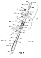
- Fig. 1 illustrates an exploded assembly view of an exemplary embodiment of a safety scalpel 100.
- the safety scalpel 100 can have a longitudinal axis 201 and comprise a handle 200 and a cartridge assembly 300.
- the cartridge assembly 300 which in many embodiments may be disposable, can be detachably mounted on the handle 200.
- the cartridge assembly 300 can be mounted on the handle 200 by sliding the cartridge assembly 300 substantially parallel to the longitudinal axis 201.
- the handle 200 can have a wall or a stopping surface for limiting how far the cartridge assembly 300 can slide onto the handle 200.
- the cartridge assembly 300 includes a shield 400, which may also be referred to as a blade guard, a guard, or housing; a slider 500, which may also be referred to as a blade holder; a blade 600; and an activation member 700, which may also be referred to as a button.
- a shield 400 which may also be referred to as a blade guard, a guard, or housing
- a slider 500 which may also be referred to as a blade holder
- a blade 600
- an activation member 700 which may also be referred to as a button.
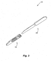
- Fig. 2 illustrates a front, perspective view of the handle 200 and the cartridge assembly 300 before assembly of the safety scalpel 100.
- Fig. 3 is a rear, perspective view of the handle 200 and the cartridge assembly 300 before assembly of the safety scalpel 100.
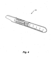
- Fig 4 to Fig. 6 show the safety scalpel 100 after assembly.
- Fig. 4 is a front, perspective view of the safety scalpel 100 with a blade in a retracted position within the shield 400.
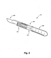
- Fig. 5 is a front, perspective view of the safety scalpel 100 with the blade 600 in an extended position outside the shield 400.
- Fig. 6 is a rear, perspective view of the safety scalpel 100 with the blade 600 in a retracted position.
- the handle 200 of the safety scalpel 100 includes a first end 202 and a second end 204.
- the handle 200 generally includes three portions which are:-a holding portion 210, a locking portion 220, and an engaging portion 230.
- the holding portion 210 extends from the first end 202 to the locking portion 220.
- the engaging portion 230 extends from the second end 204 to the locking portion 220.
- the holding portion 210 of the handle 200 can include indicia. It may be desirable for the user of the safety scalpel 100 to make measurements or to calculate lengths while in use. Indicia, such as a scale 212 , can be printed or etched on at least one side of the holding portion of the handle 200. In many embodiments, the scale 212 can be in inches, centimeters, millimeters, and the like.
- the locking portion 220 of the handle 200 can engage an end of the cartridge assembly 300. As described in detail below, the locking portion 220 engages an end of the shield 400 and is keyed to mate with the shield 400 to reduce, if not eliminate, wobble of the cartridge assembly. 300 relative to the handle 200.
- the engaging portion 230 of the handle is adapted to be received in a hollow cavity of the cartridge assembly 300.
- the engaging portion 230 includes a rising ramp 232 along each of the opposing sides of the engaging portion 230, a defined cutout 234, a keyway 236 configured to receive a portion of the slider 500, a wobble prevention detent or bump 238, and an aperture 240 configured to receive a tab 410 from the shield 400 for locking the cartridge assembly 300 to the handle 200.
- the bump 238 engages with the slider 500 to prevent the blade 600 from wobbling when the safety scalpel 100 is operated in an operating position in a first direction whereas the keyway 236 of the handle 200 cooperates with an extending member 502 of the slider 500 (as shown in Fig. 11B ) to prevent wobbling in a second direction.
- Fig. 8A is a front, perspective view of the cartridge assembly 300 with the blade 600 in a retracted position.
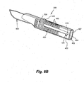
- Fig. 8B is a front, perspective view of the cartridge assembly with a blade in an extended position.
- the cartridge assembly 300 has a shield or blade guard 400, a slider or blade holder 500 slideably mounted within a cavity 402 of the shield or blade guard 400, a blade 600, and a button 700 or an activation member 700
- Fig. 9 is a rear, perspective view of the cartridge assembly 300,
- the shield 400 of the cartridge assembly 300 can be elongate, and having a substantially rectangular cross-section.
- the shield 400 can be substantially hollow, defining a cavity 402, and adapted to slide onto the second end 204, and cover up substantially the engaging portion 230, of the handle 200.
- the slider 500 can be disposed within the cavity 402 defined by the shield 400. In some embodiments, the slider 500 can slide along rails 415 positioned within the cavity 402 of the shield 400.
- the shield 400 extends from a first end 404, which is adapted to engage the locking portion 220 of the handle, to a second end 406.
- the first end 404 is a handle engaging end
- the second end 406 is blade engaging end.
- the cartridge assembly 300 can be locked in position relative to the handle 200 once it is mounted onto the engaging portion 230 of the handle 200.
- the shield 400 of the cartridge assembly 300 can include a locking snap 410, which can be positioned on a second side of the shield 400.
- the locking snap or tab 410 engages the aperture 240 on the engaging portion of the handle 200 to prevent the cartridge assembly 300 from sliding off the handle 200 after it has been attached thereto.
- the aperture 240 can receive the locking snap 410.
- the safety scalpel 100 of the present invention prevents accidental removal of the cartridge assembly 300 .
- the cartridge assembly 300 can be disposable.
- a worker removes the cartridge assembly 300 from the handle 200.
- the worker may need to implement forceps, pliers, or another like device.
- a nose of the device can lift the locking snap 410 of the shield 400 from the aperture 240 of the handle 200.
- Conventional designs enable the disassembly of the cartridge assembly 300 from the handle 200, but with dangerous consequences, including the potential of removal during use of the scalpel.
- the safety scalpel 100 prevents the accidental removal of the cartridge assembly 300 from the handle 200, as it requires the positive action of lifting the locking snap 410 from the aperture 240.
- the shield 400 can have a slot 420 extending longitudinally along a first side.
- the slot 420 extends from a slider disengaged end 422, near the first end 404 of the shield 400, to a slider engaged end 424, near the second end 406.
- the slider 500 can further carry the button 700.
- the button 700 can be travel along the slot 420 from the first end (slider disengaged end 422) to the second end (slider engaged end 424 ), and back.
- the button 700 can be attached to the slider 500 by a stem 702.
- a head 704 of the button 700 can be disposed outside of the shield 400 while the slider 500 remains within the shield 400.
- At least one side of the shield 400 can include a grip 430.
- the grip 430 can comprise a plurality of u-shaped cutouts defined along the surface of a side of the shield 400. As illustrated in the figures, the grip 430 can be placed on more than one side/surface.
- a position indicator or extending member 440 can extend from at least one side of the shield 400.
- the position indicator 440 provides an immediate both visual and feel/touch indication of the location of the scalpel 100 by mimicking the transition step between handle and blade on a traditional scalpel that may be used to locate position or provide a tactile grip to prevent slippage. This can be helpful to determine how far the blade 600 is in the surface being cut, or generally to have a feel for where the blade is, and can provide mechanical leverage to prevent slippage during use.
- the position indicator 440 provides an immediate indication of how far a surgeon has cut into the epidermis or tissue of a patient.
- the slider 500 which is generally shown in Figs. 1 and 11A to 11B, can slidably engage the handle 200 and shield 400. As the slider 500 slides relative to the shield 400 and handle 200, the slider 500 and the blade 600 can extend from within the shield 400 and retract back into the shield 400.
- a user such as a surgeon or healthcare professional, can extend the blade 600 from within the shield 400 by moving the button 700 from the slider disengaged end 422 to the slider engaged end 424. The user can retract the blade 600 back into the shield 300 by moving the button 700 from the slider engaged end 424 back to the slider disengaged end 422.
- the safety scalpel 100 can be stored with the blade 600 in the retracted position within the shield 400. In this position, the blade 600 is completely within the shield 400, wherein neither a point 602 nor a sharp, cutting edge 604 of the blade 600 is exposed.
- Handling the scalpel 100 is safer with the blade 600 in the retracted position as accidental cuts can be avoided.
- the procedure of a nurse or scrub tech passing the scalpel 100 to a surgeon is made substantially safer as the edge of the blade 600 is not exposed and cannot cut either the surgeon or the nurse.
- the slider 500 can be locked within the shield 400 to prevent the blade 600 from extending from within the housing 300 when the cartridge assembly 300 is not mounted on the handle 200.
- Figs. 1-2 , 4-5 , and 7A-7C illustrate perspective frontal views of an exemplary embodiment of a scalpel handle 200.
- the scalpel handle 200 can comprise a longitudinal axis 201, a holding portion 210 for gripping by the user, and an engaging portion 230 for receiving the blade cartridge 300.
- the engaging portion 230 comprises approximately half the length of the scalpel handle 200 and the holding portion 210 comprises the remaining half.
- the locking portion 220 is sized and shaped to cooperatively fit within the first end 402 of the shield 400.
- the engaging portion 230 of the handle 200 can be narrower and substantially thinner than the holding portion 210, so that it can fit within the cartridge assembly 300.
- the engaging portion 230 can include a tapered tip 242 for improved insertion into the protective blade housing 300 and assembly of the safety scalpel 100.
- a longitudinal groove or keyway 236 can be disposed along the engaging portion 230 of the handle 200 to accommodate and receive an extending member 502 of the slider 500 after mounting of the blade 600 to the slider 500 via a blade detent 504 and heat stakes.
- the handle 200 can also include a wobble prevention detent 238, which is positioned in the engaging portion 230 of the handle.
- the wobble prevention detent 238, which in some embodiments is a bump or outwardly extending member, extends upwardly from the handle 200 and engages the slider 500 when the cartridge assembly 300 is positioned on the handle 200.
- the wobble prevention detent 238 can press on a bottom of the slider 500 and stabilize the blade 600 when the blade 600 extends from the cartridge assembly 300 and is in use.
- the handle portion 210 can include a plurality of grooves positioned on the front and/or back of the handle 200. The plurality of grooves can prevent slippage of the safety scalpel 100 during use.
- the holding portion 230 of the scalpel handle 200 can include indicia 212.
- the indicia 212 can be generally located on the front face of the scalpel handle 200.
- the indicia 212 can include multiple markings or printings, the indicia 212 are preferably units of measurement such as, but not limited to, the metric system, the Imperial system, or many other appropriate measuring systems.
- the handle 200 is designed to accept the cartridge assembly 300, and provide the user with the feel of a conventional scalpel when used. It is thus can be provided of materials, weight, and design for comfortable use by the user.
- the handle 200 and the blade 600 can be made stainless steel, while the shield 400, the slider 500, and the button 700 are made of polycarbonate material(s).
- Figs. 1-6 and 8A-10D illustrates perspective views of the shield 400.
- the shield 400 can comprise a longitudinal axis, and can be elongate with a generally rectangular cross-section.
- the shield 400 is hollow, defining a cavity 402, having a first opening 407 at the first end 404 and a second opening 409 at the second end 406.
- the shield 400 can comprise a slot 420 spanning the front side wall.
- the slot 420 can be elongate and oriented substantially parallel to the axis 201 of the scalpel 100.
- the slot 420 can comprise openings 422 and 424 at ends of the slot 420, i.e., the slider disengaging end 422 and slider engaging end 424.
- the slots 422 and 424 can have an extension 425 for maintaining the slider in a set position.
- the slider 500 can be inserted and housed within the shield 400.
- the stem 702 of the button 700 can be passed through the stem receiving aperture 506 of the slider 500 while the head 704 remains outside of the shield 400.
- the stem receiving aperture 506 is wide enough to accommodate the stem 702 of the button 700.
- a user can move the slider 500 within the shield 400 by first pushing down (towards the shield 500) and pushing or pulling on the button 700 in direction desired.
- the slot 420 prevents the slider 500 from moving in any direction except longitudinally parallel of the length of the shield 400 by limiting movement of the stem 702 of the button 700.
- the slot 420 also limits the total distance the slider 500 can travel because the stem 702 can only move within the confines of the slot 420.
- the head 704 of the button 700 can have a plurality of ridges 705 on its surface to provide the user with a better grip when engaging the button 700.
- the safety scalpel 100 is configured to extend/retract the blade 600.
- this familiar/intuitive action is similar to using a conventional box cutter device.
- the present safety scalpel 100 is adapted to extend and retract the blade 600 by pushing downward on the button 700 and then sliding it laterally along the shield 400.
- the shield 400 can be attached to the scalpel handle 200 by inserting the engaging portion 230 of the handle 200 through the first opening 407 of the shield 400.
- the shield 400 can slide along the engaging portion 230 until the end of the shield 400 abuts against the wall of the locking portion 220 of the handle 200, and the locking snap 410 engages the aperture 240.
- the shield 400 can be detached from the handle by lifting the locking snap 410 from the aperture 240 . This may require the use of a set of forceps, long nose pliers, or other similar tools. Once the locking snap 410 has been removed from the aperture 240, the shield 400, and more generally the cartridge assembly 300, can be removed by pulling the shield 400 in away from the holding portion 210 of the handle 200.
- the slider engaging end 424 can facilitate locking the slider 500 in the extended position. This end secures the slider 500 in the extended position and prevents forces in the direction of the first end 404 generated by pressing the scalpel against an object from pushing the slider or blade holder 500 back into the protective blade housing 300.
- the slider 500 can be retracted by pressing the button 700 to disengage it from the slider engaging end 424, and pulling the button 700 in the direction of the first end 404.
- the slider 500 can be locked within the shield 400 when the cartridge assembly 300 is not mounted to the handle to prevent accidental extension of the blade 600.
- the shield 400 can comprise a slider locking aperture 450 located near the first end 404.
- the slider 500 includes a pair of legs-at least one front leg 510 and at least one rear leg 520.
- the rear leg 520 can include a front pair of feet 522 and 524 as well as a pair of back feet 526 and 528.
- the rear back feet 526 and 528 which can be spring loaded, are receivable in the locking aperture 450, which may comprise one or more holes.
- the locking aperture 450 can include two separate and distinct apertures, each of which receives at least one of the rear back feet 526 or 528. Because the rear back feet 526 and 528 of the shield 400 are locked within the locking aperture of the shield 400, the slider 500, which also carries the blade 600, cannot be moved to extend from the shield 400 and thus once assembled cannot accidentally cut or injure a user.
- a fully assembled cartridge assembly 300 includes the blade 600 carried by the slider 500.
- the blade 600 has a blade point 602, a cutting edge 604, and a slider aperture 606.
- the extending member 504 of the slider 500 can engage and thus be received by the slider aperture 606 of the blade 600.
- the slider aperture 606 and the extending member 504 are keyed to cooperatively mate with one another.
- the slider 500 is then positionable within the cavity 402 of the shield 400.
- the slider 500 carrying the blade 600 can he inserted into the second opening 409 at the second end 406 of the shield 400.
- the button 700 can be connected to the slider 500.
- the button 700 has a head 704 have a first surface 706 and a second surface 707.
- the head 704 can have a stern 702 extending from the first surface 706.
- the head 704 can also comprise a plurality of ridges 705 on the second surface 707.
- the stem 702 can be inserted into the stem receiving aperture 506 of the slider 500 .
- a heat stake hole 455 is positioned on the side of the shield 400 that opposes the slot 420.
- the required heat can be applied through the heat stake hole 455 to couple the stem 702 of the button to the slider 500 .
- the button 700 can be slid along the slot 420, such that the slider 500 can be locked near the first end 404 of the shield 400. In this position, the rear leg 520 can be received in the locking aperture 450 of the shield 400.
- the slider 500 can be locked in the shield 400 by having its rear back feet 526 and 528 engage the aperture 450 of the shield 400. As a result, the slider 500 cannot be moved, unless placed on the handle 200 , and the blade 600 does not extend from the shield 400.
- the slider 500 can be varied between an extending or engaging position, wherein the blade 600 can be used, or a disengaging or secured position, wherein the blade 600 is housed.
- the cartridge assembly 300 can be secured to the engaging portion 230 of the handle 200.
- the second end 204 of the handle 200 can be inserted into first opening 407 at the first end 404 of the shield 400.
- the handle 200 includes a pair of ramps 232 along opposing sides of the engaging portion 230.
- the extending member 502 of the slider 500 is sized to fit within the keyway 236 of the engaging portion 230.
- the cartridge assembly 300 receives the engaging portion 230 of the handle 200, the extending member 502 engages the keyway 236 and the rear leg 520 slide along the ramp 232.
- the first end 404 of the shield receives the locking portion 220 of the handle 200.
- the locking portion 220 is insertable into a portion of the first opening 407 of the first end 404 of the shield 400.
- the first opening 407 can have chamfered corners to cooperatively engage the locking portion 220.
- the rear feet 520 of the slider 500 slides along the ramp 232. This causes the rear feet 520 to lift up and out of the locking aperture 450 of the shield 400. Consequently, when the button 700 is depressed, the slider 500 can slide within the shield 400 and the button 700 can slide along the slot 420 of the shield 400 to ultimately expose and extend the blade 600.
- the cutout 234 is sized and shaped to receive the necessary portion of the slider 500 to enable the slider 500 to move along the engaging portion 230 of the handle 200.
- the second opening 409 near second end of the shield 400 can be configured to allow the slider 500 to extend the blade 600 in direction outside of the shield 400 as the user moves the button 700 in the direction to extend the blade 600.
- the blade 600 can be heat staked to the slider 500. That is, the blade 600 can be secured to the slider 500 by applying heat, which locks the blade 600 securely in position.
- Figs. 14A and 14B illustrate perspective views of an exemplary embodiment of a slider 500 with a blade 600 attached thereto.
- the blade 600 can be made of a variety of suitable materials including, but not limited to, both carbon and stainless steel.
- the carbon and stainless steel used to create the blade 600 are manufactured in compliance with several industry standards including British Standard (“BS”) 2982:1992, International Organization for Standardization (“ISO”) 7740:1985 and European Standard (“EN”) 27740:1992.
- the blade 600 further can be sterilized by, for example, gamma radiation.
- Figs. 1-6 and 8A-9, 15A to 15B illustrate perspective views of exemplary embodiments of the cartridge assembly 300 .
- the cartridge assembly 300 can comprise the shield 400, slider 500, and blade 600 .
- the cartridge assembly 300 can be attached to the handle 200, and easily removed for disposal and/or replacement.
- the cartridge assembly 300 can be securely fitted onto the engaging portion 230 of the scalpel handle 200 by inserting the second end 204 through the first opening 407.
- the locking snap 410 can engage the aperture 240 to secure the cartridge assembly 300 onto the handle 200, preventing the cartridge 300 from sliding off the handle 200 during use.
- the slider 500 can be disposed within the shield 400, between the engaging portion 230 of the scalpel handle 200 and a front side wall of the shield 400.
- the slider 500 can slide over the engaging portion 230 as a user moves the button 700.
- the slider 500 can be retracted from the locked position by depressing and pulling the button 700 towards the second end 406 of the shield 400.
- the scalpel 100 is designed to be stored and handled with the slider 500 fully retracted. In this position, the blade 600 is fully enveloped by the shield 400, and the scalpel 100 is safe to handle because the sharp edge of the blade 600 is not exposed.
- the cartridge assembly 300 can be removed from the handle 200, when the slider 500 is in the retracted position. This involves removing the locking snap 410 from the aperture 240.
- Fig. 15A is a perspective view of the cartridge assembly 300 before insertion of the handle 200.
- the spring loaded rear back feet 526, 528 is configured to prevent extension of the blade 600 without insertion of the handle 200.
- the back feet 526, 528 are locked within the slider locking apertures 450 located near the first end 404 of the shield, In this way, the slider 500 with the blade 600 is locked within the shield 400 to prevent the blade 600 from accidentally extending out of the shield without mounting the handle.
- the back feet 526, 528 can be lifted or raised out of from the apertures 450 by inserting the handle 200.
- each of the ramps 232 lifts the respective feet 526, 528.
- a locking snap 410 of the shield 400 engages the aperture 240 on the engaging portion of the handle 200 to prevent the cartridge assembly 300 from sliding off the handle 200 after it has been attached thereto.
- the aperture 240 can receive the locking snap 410.
- the cartridge assembly 300 can be detached from the handle 200 by two hands and an external instrument, for example, by using the external instrument to lift the locking snap 410 from the aperture 240.
- the locking snap 410 can be lifted from the aperture 240 by an unlock tool suitable for unlocking a snap lock or a locking snap so as to detach the cartridge assembly 300 from the handle 200.
- the unlock tool may be tweezers.
- the advantage of only using an external instrument to detach the cartridge assembly 300 is to prevent accidental detachment of the cartridge assembly 300 from the handle 200 during an inadvertent hand action when in an operating position or during handling of the safety scalpel 100.
- the handle 200 and in particular, the surfaces for gripping such as the holding portion 210 of the handle 200, can be made of or coated with a anti-slip material such as rubber material that can improve the friction between the hand and the grip surfaces.
- a anti-slip material such as rubber material that can improve the friction between the hand and the grip surfaces.
- the holding portion 210 may be coated with a synthetic rubber material.
- the handle 200 can be made of a metal material.
- the blade guard, the blade holder, and the activation member can be made of materials not limited to plastics, such as a thermoplastic material such as for example, polycarbonate materials.
- the invention provides a number of cutting devices.
- the various embodiments of the invention described above provide a safety scalpel having a handle for holding a cutting portion and a disposable cartridge assembly.
Landscapes
- Health & Medical Sciences (AREA)
- Life Sciences & Earth Sciences (AREA)
- Surgery (AREA)
- Heart & Thoracic Surgery (AREA)
- Engineering & Computer Science (AREA)
- Biomedical Technology (AREA)
- Nuclear Medicine, Radiotherapy & Molecular Imaging (AREA)
- Medical Informatics (AREA)
- Molecular Biology (AREA)
- Animal Behavior & Ethology (AREA)
- General Health & Medical Sciences (AREA)
- Public Health (AREA)
- Veterinary Medicine (AREA)
- Surgical Instruments (AREA)
Description
- This Application claims priority to
U.S. Provisional Patent Application No. 61/359,249 - Embodiments of the present invention relate to cutting devices and, more particularly, to safety scalpels for medical use.
- Health care is the second fastest growing sector of the U.S. economy, employing over 12 million workers. Health care workers face a wide range of hazards on the job-including needlestick and sharps injuries, back injuries, latex allergies, violence, and stress. Although it is possible to prevent or reduce health care worker exposure to these hazards, health care workers are actually experiencing increasing numbers of occupational injuries and illnesses. Rates of occupational injury to health care workers continue to rise, as they have over the past decade. By contrast, two of the most hazardous industries, agriculture and construction, are safer today than they were a decade ago.
- Precise national data is not available on the annual number of needlestick and other percutaneous injuries among health care workers; however, estimates indicate that 600,000 to 800,000 such injuries occur annually. About half of these injuries go unreported. Data from EPINet (the Exposure Prevention Information Network) suggests that at an average hospital, workers incur approximately thirty needlestick injuries per 100 beds per year.
- Most reported needlestick and sharps injuries involve nursing staff, but laboratory staff, physicians, housekeepers, and other health care workers are also injured. Some of these injuries expose workers to bloodborne pathogens that can cause infection. The more serious of these pathogens are the hepatitis B virus (HBV), the hepatitis C virus (HCV), and the human immunodeficiency virus (HIV). Infections by each of these pathogens are potentially life threatening, yet preventable.
- The emotional impact of needlestick and sharps injuries can be severe and long lasting, even when a serious infection is not transmitted. This impact is particularly severe when the injury involves exposure to HIV. In one study of twenty health care workers with an HIV exposure, eleven reported acute severe distress, seven had persistent moderate distress, and six quit their jobs as a result of the exposure. Other stress reactions requiring counseling have also been reported. Not knowing the infection status of the source patient can accentuate the health care worker's stress. In addition to the exposed health care worker, colleagues and family members may suffer emotionally.
- Safety and health issues can best be addressed in the setting of a comprehensive prevention program that considers all aspects of the work environment and that has employee involvement as well as management commitment. Implementing the use of improved engineering controls is one component of such a comprehensive program. Other prevention strategy factors that must be addressed, however, include modification of hazardous work practices, administrative changes to address needle hazards in the environment (e.g., prompt removal of filled sharps disposal boxes), safety education and awareness, feedback on safety improvements, and action taken on continuing problems.
- Improved engineering controls are often among the most effective approaches to reducing occupational hazards and, therefore, are an important element of a needlestick prevention program. Such controls include eliminating the unnecessary use of needles and implementing devices having safety features. A number of sources have identified several desirable characteristics for safety devices, which include preferences for safety devices that: do not use needles; incorporate the safety feature as an integral part of the device; work passively (i.e., requires no activation by the user); have a safety feature that can be engaged with a single-hand technique and allows the worker's hands to remain behind the exposed sharp, if user activation is necessary; allow the user to easily determine whether the safety feature is activated; have a safety feature that cannot be deactivated and remains protective through disposal; perform reliably; are easy to use and practical; and are safe and effective for patient care.
- Although each of these characteristics is desirable, some are not feasible, applicable, or available for certain health care situations. For example, needles will always be necessary where alternatives for skin penetration are not available. Also, a safety feature that requires activation by the user might be preferable to one that is passive in some cases. Each device must be considered on its own merit and ultimately on its ability to reduce workplace injuries.
- Regarding specifically scalpels, the conventional scalpel currently used in the healthcare industry includes a metal handle and a disposable blade that is mounted on the handle prior to use, and removed after use, The process of mounting and dismounting the blade is a difficult and dangerous procedure, which exposes the medical practitioner to potential injury from the exposed blade and contamination due to blood that may be present on the blade.
- An additional danger exists during operations. When a surgeon requests a particular scalpel, a nurse, physician's assistant, or scrub technician must hand the scalpel to the surgeon with the handle end pointed toward the surgeon, so the surgeon can easily grasp the scalpel, Consequently, the nurse must hold the scalpel by the end having an exposed blade. As a result, the nurse is often cut by the blade during the hand off. Similarly, when the surgeon returns the scalpel to the nurse, the surgeon presents the nurse with the blade end, which the nurse must grab without cutting herself/himself.
- Surgeons who have developed a feel for the shape and weight of the metal handle dislike the current disposable safety scalpels as, among other things, the plastic handle is too light and feels "different." During use, the plastic handle of the scalpel incurs more undesirable flexibility than that of a metal handle scalpel. In addition, the disposable safety scalpel is significantly more expensive than the regular disposable blade. These two factors currently limit the adoption of safety scalpels in the healthcare industry.
-
US 2007/265651 A1 , on which the preamble of claim 1 is based, describes a safety scalpel having a disposable blade cartridge, a non-disposable scalpel handle having a distal end. The disposable blade cartridge has a blade, a blade holder in communication with the blade, and a blade guard for receiving the blade and the blade holder. The disposable blade cartridge is slidable onto the distal end of the non-disposable scalpel handle and is lockable to the non-disposable scalpel handle. -
EP 0 958 788 A1 describes a surgical scalpel having an elongate handle that has a proximal end, an open distal end and sidewalls that define an upwardly open cavity with a bottom with an open void therein. The scalpel has a cartridge that is removably retained within the cavity, a shield and a blade holder mounted within the shield. - What is needed is a safe and reliable scalpel that overcomes the present objections from the healthcare practitioner of current designs, while providing adequate protection for the medical workers handling the scalpel,
- Briefly described, embodiments of the present invention relate to a safety scalpel, The safety scalpel is an improvement over the conventional scalpel by providing a safety scalpel that incorporates a handle similar in thickness, length, weight, balance, shape and feel to the conventional metal handle preferred by most surgeons, and a cartridge assembly that is easily mounted and released from the scalpel handle. The handle can be reusable and made of a metal. The cartridge assembly can be made of disposable materials and thus can be preferably detachable from the handle. The cartridge assembly comprises a shield, a slider carrying a blade, and a button to move the blade between engaging and disengaging positions. For example, the blade extends from the housing during use and is fully housed in the housing when the scalpel is not being used.
- In an exemplary embodiment, the safety scalpel can comprise a handle having a first end and a second end, a cartridge assembly comprising a shield fitting onto the second end of the handle, a slider disposed within the shield, and a blade attached to the slider.
- The second end of the handle can be generally flat and narrower than the first end of the handle. The shield can be generally elongate, generally rectangular in cross-section, and substantially hollow. The second end of the handle can be inserted into the shield and secured thereto to define a cavity. A locking snap incorporated into the shield can engage a defined aperture of the handle to lock the cartridge onto the handle.
- In some embodiments, when the cartridge assembly is fully assembled the blade housed therein cannot be extended unless it is placed on the handle. This feature prevents accidental extension of the blade and reduces injuries.
- In some embodiments, the safety scalpel is configured to extend/retract. For example, this familiar/intuitive action is similar to using a conventional box cutter device. As opposed to some of the conventional scalpels, where the user must slide the shield backwards to expose the blade and even more awkwardly slide the shield forward to consciously cover the blade, the present safety scalpel is adapted to extend and retract by pushing downward on the button and then sliding along the shield to change its position.
- Further features of embodiments of the present invention, and the advantages offered thereby, are explained in greater detail hereinafter with reference to specific embodiments illustrated in the accompanying drawings, wherein like elements are indicated by like reference designators.
-
-
Fig. 1 is an exploded assembly view of a safety scalpel, in accordance with an exemplary embodiment of the present invention. -
Fig. 2 is a front, perspective view of a handle and a cartridge assembly of the safety scalpel, in accordance with an exemplary embodiment of the present invention. -
Fig. 3 is a rear, perspective view of the handle and the cartridge assembly of the safety scalpel, in accordance with an exemplary embodiment of the present invention. -
Fig. 4 is a front, perspective view of the safety scalpel with a blade in a retracted position, in accordance with an exemplary embodiment of the present invention. -
Fig. 5 is a front, perspective view of the safety scalpel with a blade in an extended position, in accordance with an exemplary embodiment of the present invention. -
Fig. 6 is a rear, perspective view of the assembled safety scalpel with a blade in a retracted position, in accordance with an exemplary embodiment of the present invention. -
Fig. 7A is a front view of the handle of the safety scalpel, in accordance with an exemplary embodiment of the present invention. -
Fig. 7B is a rear view of the handle of the safety scalpel, in accordance with an exemplary embodiment of the present invention. -
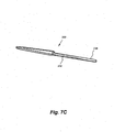
Fig. 7C is a side view of the handle of the safety scalpel, in accordance with an exemplary embodiment of the present invention. -
Fig. 8A is a front, perspective view of the cartridge assembly of the safety scalpel, in accordance with an exemplary embodiment of the present invention. -
Fig. 8B is a front, perspective view of the cartridge assembly of the safety scalpel with an exposed blade, in accordance with an exemplary embodiment of the present invention. -
Fig. 9 is a rear, perspective view of the cartridge assembly of the safety scalpel, in accordance with an exemplary embodiment of the present invention. -
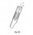
Fig. 10A is a front, perspective view of a shield of the cartridge assembly of the safety scalpel, in accordance with an exemplary embodiment of the present invention. -
Fig. 10B is a rear perspective view of the shield of the cartridge assembly of the safety scalpel, in accordance with an exemplary embodiment of the present invention. -
Fig. 10C is an end perspective view of the shield of the cartridge assembly of the safety scalpel, in accordance with an exemplary embodiment of the present invention. -
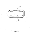
Fig. 10D is an end view into a hollow cavity of the shield of the cartridge assembly, in accordance with an exemplary embodiment of the present invention. -
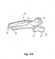
Fig. 11A is a top, perspective view of a slider of the cartridge assembly of the safety scalpel, in accordance with an exemplary embodiment of the present invention. -
Fig. 11B is a bottom, perspective view of the slider of the cartridge assembly of the safety scalpel, in accordance with an exemplary embodiment of the present invention. -
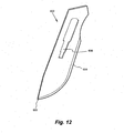
Fig. 12 is a perspective view of a blade of the cartridge assembly of the safety scalpel, in accordance with an exemplary embodiment of the present invention. -
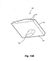
Fig. 13A is a top perspective view of a button of the cartridge assembly of the safety scalpel, in accordance with an exemplary embodiment of the present invention. -
Fig. 13B is a bottom, perspective view of the button of the safety scalpel, in accordance with an exemplary embodiment of the present invention. -
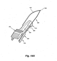
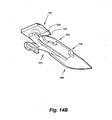
Fig. 14A is a top, perspective view of the slider of the cartridge assembly of the safety scalpel carrying a blade, in accordance with an exemplary embodiment of the present invention. -
Fig. 14B is a bottom, perspective view of the slider of the cartridge assembly of the safety scalpel carrying the blade, in accordance with an exemplary embodiment of the present invention. -
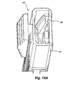
Fig. 15A is a perspective view of a cartridge assembly in accordance with an exemplary embodiment of the present invention. -
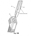
Fig. 15B is a perspective view of the cartridge assembly before insertion of a handle to form a safety scalpel in accordance with an exemplary embodiment of the present invention. - Although preferred embodiments of the invention are explained in detail, it is to be understood that other embodiments are contemplated. Accordingly, it is not intended that the invention is limited in its scope to the details of construction and arrangement of components set forth in the following description or illustrated in the drawings. The invention is capable of other embodiments and of being practiced or carried out in various ways. Also, in describing the preferred embodiments, specific terminology will be resorted to for the sake of clarity.
- It must also be noted that, as used in the specification and the appended claims, the singular forms "a," "an" and "the" include plural referents unless the context clearly dictates otherwise.
- Also, in describing the preferred embodiments, terminology will be resorted to for the sake of clarity. It is intended that each term contemplates its broadest meaning as understood by those skilled in the art and includes all technical equivalents which operate in a similar manner to accomplish a similar purpose.
- Ranges may be expressed herein as from "about" or "approximately" one particular value and/or to "about" or "approximately" another particular value. When such a range is expressed, another embodiment includes from the one particular value and/or to the other particular value.
- By "comprising" or "containing" or "including" is meant that at least the named compound, element, particle, or method step is present in the composition or article or method, but does not exclude the presence of other compounds, materials, particles, method steps, even if the other such compounds, material, particles, method steps have the same function as what is named.
- It is also to be understood that the mention of one or more method steps does not preclude the presence of additional method steps or intervening method steps between those steps expressly identified. Similarly, it is also to be understood that the mention of one or more components in a device or system does not preclude the presence of additional components or intervening components between those components expressly identified.
- Referring now in detail to the figures, wherein like reference numerals represent like parts throughout the several views,
Fig. 1 illustrates an exploded assembly view of an exemplary embodiment of asafety scalpel 100. Thesafety scalpel 100 can have alongitudinal axis 201 and comprise ahandle 200 and acartridge assembly 300. Thecartridge assembly 300, which in many embodiments may be disposable, can be detachably mounted on thehandle 200. Preferably, thecartridge assembly 300 can be mounted on thehandle 200 by sliding thecartridge assembly 300 substantially parallel to thelongitudinal axis 201. Thehandle 200 can have a wall or a stopping surface for limiting how far thecartridge assembly 300 can slide onto thehandle 200. - As shown in the figures, in particular,
Figs. 1 and8A , thecartridge assembly 300 includes ashield 400, which may also be referred to as a blade guard, a guard, or housing; aslider 500, which may also be referred to as a blade holder; ablade 600; and anactivation member 700, which may also be referred to as a button. -
Fig. 2 illustrates a front, perspective view of thehandle 200 and thecartridge assembly 300 before assembly of thesafety scalpel 100. -
Fig. 3 is a rear, perspective view of thehandle 200 and thecartridge assembly 300 before assembly of thesafety scalpel 100. -
Fig 4 to Fig. 6 show thesafety scalpel 100 after assembly.Fig. 4 is a front, perspective view of thesafety scalpel 100 with a blade in a retracted position within theshield 400.Fig. 5 is a front, perspective view of thesafety scalpel 100 with theblade 600 in an extended position outside theshield 400.Fig. 6 is a rear, perspective view of thesafety scalpel 100 with theblade 600 in a retracted position. - As shown in
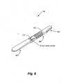
Fig. 1 andFig. 7A to 7C , thehandle 200 of thesafety scalpel 100 includes afirst end 202 and asecond end 204. Thehandle 200 generally includes three portions which are:-aholding portion 210, a lockingportion 220, and an engagingportion 230. The holdingportion 210 extends from thefirst end 202 to the lockingportion 220. The engagingportion 230 extends from thesecond end 204 to the lockingportion 220. - The holding
portion 210 of thehandle 200 can include indicia. It may be desirable for the user of thesafety scalpel 100 to make measurements or to calculate lengths while in use. Indicia, such as ascale 212, can be printed or etched on at least one side of the holding portion of thehandle 200. In many embodiments, thescale 212 can be in inches, centimeters, millimeters, and the like. - The locking
portion 220 of thehandle 200 can engage an end of thecartridge assembly 300. As described in detail below, the lockingportion 220 engages an end of theshield 400 and is keyed to mate with theshield 400 to reduce, if not eliminate, wobble of the cartridge assembly. 300 relative to thehandle 200. - The engaging
portion 230 of the handle is adapted to be received in a hollow cavity of thecartridge assembly 300. The engagingportion 230 includes a risingramp 232 along each of the opposing sides of the engagingportion 230, a definedcutout 234, akeyway 236 configured to receive a portion of theslider 500, a wobble prevention detent or bump 238, and anaperture 240 configured to receive atab 410 from theshield 400 for locking thecartridge assembly 300 to thehandle 200. Thebump 238 engages with theslider 500 to prevent theblade 600 from wobbling when thesafety scalpel 100 is operated in an operating position in a first direction whereas thekeyway 236 of thehandle 200 cooperates with an extendingmember 502 of the slider 500 (as shown inFig. 11B ) to prevent wobbling in a second direction. -
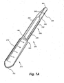
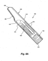
Fig. 8A is a front, perspective view of thecartridge assembly 300 with theblade 600 in a retracted position.Fig. 8B is a front, perspective view of the cartridge assembly with a blade in an extended position. As shown inFigs. 8A and8B , thecartridge assembly 300 has a shield orblade guard 400, a slider orblade holder 500 slideably mounted within acavity 402 of the shield orblade guard 400, ablade 600, and abutton 700 or anactivation member 700,Fig. 9 is a rear, perspective view of thecartridge assembly 300, - As shown in
Figs. 1-6 and 8A, 8B, 9, 10A to 10D, and 11, theshield 400 of thecartridge assembly 300 can be elongate, and having a substantially rectangular cross-section. Referring toFig. 10A , theshield 400 can be substantially hollow, defining acavity 402, and adapted to slide onto thesecond end 204, and cover up substantially the engagingportion 230, of thehandle 200. Theslider 500 can be disposed within thecavity 402 defined by theshield 400. In some embodiments, theslider 500 can slide along rails 415 positioned within thecavity 402 of theshield 400. - The
shield 400 extends from afirst end 404, which is adapted to engage the lockingportion 220 of the handle, to asecond end 406. In an exemplary embodiment, thefirst end 404 is a handle engaging end, and thesecond end 406 is blade engaging end. - To prevent the
cartridge assembly 300 from sliding off thehandle 200 and/or moving relative to thehandle 200 during use, thecartridge assembly 300 can be locked in position relative to thehandle 200 once it is mounted onto the engagingportion 230 of thehandle 200. Theshield 400 of thecartridge assembly 300 can include a lockingsnap 410, which can be positioned on a second side of theshield 400. The locking snap ortab 410 engages theaperture 240 on the engaging portion of thehandle 200 to prevent thecartridge assembly 300 from sliding off thehandle 200 after it has been attached thereto. In other words, theaperture 240 can receive the lockingsnap 410. - Unlike many prior art solutions, in which removing the
cartridge assembly 300 from thehandle 200 may mistakenly occur, thesafety scalpel 100 of the present invention prevents accidental removal of thecartridge assembly 300. In many embodiments, thecartridge assembly 300 can be disposable. When it is desired to dispose of thecartridge assembly 300, a worker removes thecartridge assembly 300 from thehandle 200. To remove thecartridge assembly 300, the worker may need to implement forceps, pliers, or another like device. A nose of the device can lift the lockingsnap 410 of theshield 400 from theaperture 240 of thehandle 200. Conventional designs enable the disassembly of thecartridge assembly 300 from thehandle 200, but with dangerous consequences, including the potential of removal during use of the scalpel. Thesafety scalpel 100 prevents the accidental removal of thecartridge assembly 300 from thehandle 200, as it requires the positive action of lifting the lockingsnap 410 from theaperture 240. - Referring back to the
shield 400, it can have aslot 420 extending longitudinally along a first side. Theslot 420 extends from a sliderdisengaged end 422, near thefirst end 404 of theshield 400, to a slider engagedend 424, near thesecond end 406. As described elsewhere, theslider 500 can further carry thebutton 700. Thebutton 700 can be travel along theslot 420 from the first end (slider disengaged end 422) to the second end (slider engaged end 424), and back. Thebutton 700 can be attached to theslider 500 by astem 702. Ahead 704 of thebutton 700 can be disposed outside of theshield 400 while theslider 500 remains within theshield 400. - At least one side of the
shield 400 can include agrip 430. Thegrip 430 can comprise a plurality of u-shaped cutouts defined along the surface of a side of theshield 400. As illustrated in the figures, thegrip 430 can be placed on more than one side/surface. - In addition, a position indicator or extending
member 440 can extend from at least one side of theshield 400. When thesafety scalpel 100 is being used, theposition indicator 440 provides an immediate both visual and feel/touch indication of the location of thescalpel 100 by mimicking the transition step between handle and blade on a traditional scalpel that may be used to locate position or provide a tactile grip to prevent slippage. This can be helpful to determine how far theblade 600 is in the surface being cut, or generally to have a feel for where the blade is, and can provide mechanical leverage to prevent slippage during use. For example, theposition indicator 440 provides an immediate indication of how far a surgeon has cut into the epidermis or tissue of a patient. - The
slider 500, which is generally shown inFigs. 1 and11A to 11B, can slidably engage thehandle 200 andshield 400. As theslider 500 slides relative to theshield 400 and handle 200, theslider 500 and theblade 600 can extend from within theshield 400 and retract back into theshield 400. A user, such as a surgeon or healthcare professional, can extend theblade 600 from within theshield 400 by moving thebutton 700 from the sliderdisengaged end 422 to the slider engagedend 424. The user can retract theblade 600 back into theshield 300 by moving thebutton 700 from the slider engagedend 424 back to the sliderdisengaged end 422. - The
safety scalpel 100 can be stored with theblade 600 in the retracted position within theshield 400. In this position, theblade 600 is completely within theshield 400, wherein neither apoint 602 nor a sharp, cuttingedge 604 of theblade 600 is exposed. - Handling the
scalpel 100 is safer with theblade 600 in the retracted position as accidental cuts can be avoided. In particular, the procedure of a nurse or scrub tech passing thescalpel 100 to a surgeon is made substantially safer as the edge of theblade 600 is not exposed and cannot cut either the surgeon or the nurse. - For increased safety, the
slider 500 can be locked within theshield 400 to prevent theblade 600 from extending from within thehousing 300 when thecartridge assembly 300 is not mounted on thehandle 200. -
Figs. 1-2 ,4-5 , and7A-7C illustrate perspective frontal views of an exemplary embodiment of ascalpel handle 200. The scalpel handle 200 can comprise alongitudinal axis 201, a holdingportion 210 for gripping by the user, and an engagingportion 230 for receiving theblade cartridge 300. In an exemplary embodiment, the engagingportion 230 comprises approximately half the length of the scalpel handle 200 and the holdingportion 210 comprises the remaining half. Between the holdingportion 210 and the engagingportion 230 is the lockingportion 220 that is sized and shaped to cooperatively fit within thefirst end 402 of theshield 400. - The engaging
portion 230 of thehandle 200 can be narrower and substantially thinner than the holdingportion 210, so that it can fit within thecartridge assembly 300. Preferably, the engagingportion 230 can include a taperedtip 242 for improved insertion into theprotective blade housing 300 and assembly of thesafety scalpel 100. - A longitudinal groove or
keyway 236 can be disposed along the engagingportion 230 of thehandle 200 to accommodate and receive an extendingmember 502 of theslider 500 after mounting of theblade 600 to theslider 500 via ablade detent 504 and heat stakes. - The
handle 200 can also include awobble prevention detent 238, which is positioned in the engagingportion 230 of the handle. Thewobble prevention detent 238, which in some embodiments is a bump or outwardly extending member, extends upwardly from thehandle 200 and engages theslider 500 when thecartridge assembly 300 is positioned on thehandle 200. Thewobble prevention detent 238 can press on a bottom of theslider 500 and stabilize theblade 600 when theblade 600 extends from thecartridge assembly 300 and is in use. - For increased traction of the scalpel handle 200 when in contact with a finger during use of the
safety scalpel 100, thehandle portion 210 can include a plurality of grooves positioned on the front and/or back of thehandle 200. The plurality of grooves can prevent slippage of thesafety scalpel 100 during use. - As illustrated in the figures, the holding
portion 230 of the scalpel handle 200 can includeindicia 212. Theindicia 212 can be generally located on the front face of thescalpel handle 200. Theindicia 212 can include multiple markings or printings, theindicia 212 are preferably units of measurement such as, but not limited to, the metric system, the Imperial system, or many other appropriate measuring systems. - The
handle 200 is designed to accept thecartridge assembly 300, and provide the user with the feel of a conventional scalpel when used. It is thus can be provided of materials, weight, and design for comfortable use by the user. In some embodiments, thehandle 200 and theblade 600 can be made stainless steel, while theshield 400, theslider 500, and thebutton 700 are made of polycarbonate material(s). -
Figs. 1-6 and 8A-10D illustrates perspective views of theshield 400. Theshield 400 can comprise a longitudinal axis, and can be elongate with a generally rectangular cross-section. Theshield 400 is hollow, defining acavity 402, having afirst opening 407 at thefirst end 404 and asecond opening 409 at thesecond end 406. - The
shield 400 can comprise aslot 420 spanning the front side wall. Theslot 420 can be elongate and oriented substantially parallel to theaxis 201 of thescalpel 100. Theslot 420 can compriseopenings slot 420, i.e., theslider disengaging end 422 andslider engaging end 424. Theslots extension 425 for maintaining the slider in a set position. - The
slider 500 can be inserted and housed within theshield 400. Thestem 702 of thebutton 700 can be passed through thestem receiving aperture 506 of theslider 500 while thehead 704 remains outside of theshield 400. Thestem receiving aperture 506 is wide enough to accommodate thestem 702 of thebutton 700. A user can move theslider 500 within theshield 400 by first pushing down (towards the shield 500) and pushing or pulling on thebutton 700 in direction desired. As theslider 500 moves, theslot 420 prevents theslider 500 from moving in any direction except longitudinally parallel of the length of theshield 400 by limiting movement of thestem 702 of thebutton 700. Theslot 420 also limits the total distance theslider 500 can travel because thestem 702 can only move within the confines of theslot 420. In some embodiments, thehead 704 of thebutton 700 can have a plurality ofridges 705 on its surface to provide the user with a better grip when engaging thebutton 700. - As described, the
safety scalpel 100 is configured to extend/retract theblade 600. For example, this familiar/intuitive action is similar to using a conventional box cutter device. As opposed to some of the conventional scalpels, where the user must slide the shield backwards to expose the blade and even more awkwardly slide the shield forward to consciously cover the blade, thepresent safety scalpel 100 is adapted to extend and retract theblade 600 by pushing downward on thebutton 700 and then sliding it laterally along theshield 400. - The
shield 400 can be attached to the scalpel handle 200 by inserting the engagingportion 230 of thehandle 200 through thefirst opening 407 of theshield 400. Theshield 400 can slide along the engagingportion 230 until the end of theshield 400 abuts against the wall of the lockingportion 220 of thehandle 200, and the lockingsnap 410 engages theaperture 240. - The
shield 400 can be detached from the handle by lifting the lockingsnap 410 from theaperture 240. This may require the use of a set of forceps, long nose pliers, or other similar tools. Once the lockingsnap 410 has been removed from theaperture 240, theshield 400, and more generally thecartridge assembly 300, can be removed by pulling theshield 400 in away from the holdingportion 210 of thehandle 200. - The
slider engaging end 424 can facilitate locking theslider 500 in the extended position. This end secures theslider 500 in the extended position and prevents forces in the direction of thefirst end 404 generated by pressing the scalpel against an object from pushing the slider orblade holder 500 back into theprotective blade housing 300. Theslider 500 can be retracted by pressing thebutton 700 to disengage it from theslider engaging end 424, and pulling thebutton 700 in the direction of thefirst end 404. - For additional safety, the
slider 500 can be locked within theshield 400 when thecartridge assembly 300 is not mounted to the handle to prevent accidental extension of theblade 600. As shown inFig. 1 , theshield 400 can comprise aslider locking aperture 450 located near thefirst end 404. Theslider 500, on the other hand, includes a pair of legs-at least onefront leg 510 and at least onerear leg 520. Therear leg 520 can include a front pair offeet back feet back feet aperture 450, which may comprise one or more holes. As illustrated in the figures, the lockingaperture 450 can include two separate and distinct apertures, each of which receives at least one of the rearback feet back feet shield 400 are locked within the locking aperture of theshield 400, theslider 500, which also carries theblade 600, cannot be moved to extend from theshield 400 and thus once assembled cannot accidentally cut or injure a user. - As mentioned, when the
cartridge assembly 300 is fully assembled, theblade 600 cannot accidentally extend from theshield 400. A fully assembledcartridge assembly 300 includes theblade 600 carried by theslider 500. Referring toFig. 12 , theblade 600 has ablade point 602, acutting edge 604, and aslider aperture 606. The extendingmember 504 of theslider 500 can engage and thus be received by theslider aperture 606 of theblade 600. Theslider aperture 606 and the extendingmember 504 are keyed to cooperatively mate with one another. Theslider 500 is then positionable within thecavity 402 of theshield 400. Theslider 500 carrying theblade 600 can he inserted into thesecond opening 409 at thesecond end 406 of theshield 400. - Now the
button 700 can be connected to theslider 500. Referring toFig. 13A andFig. 13B , thebutton 700 has ahead 704 have afirst surface 706 and asecond surface 707. Thehead 704 can have a stern 702 extending from thefirst surface 706. Thehead 704 can also comprise a plurality ofridges 705 on thesecond surface 707. Thestem 702 can be inserted into thestem receiving aperture 506 of theslider 500. In some embodiments, it may be desirable to heat stake the stern 702 to theslider 500. In such embodiments, aheat stake hole 455 is positioned on the side of theshield 400 that opposes theslot 420. The required heat can be applied through theheat stake hole 455 to couple thestem 702 of the button to theslider 500. Thebutton 700 can be slid along theslot 420, such that theslider 500 can be locked near thefirst end 404 of theshield 400. In this position, therear leg 520 can be received in the lockingaperture 450 of theshield 400. Theslider 500 can be locked in theshield 400 by having its rearback feet aperture 450 of theshield 400. As a result, theslider 500 cannot be moved, unless placed on thehandle 200, and theblade 600 does not extend from theshield 400. - When the
cartridge assembly 300 is coupled to thehandle 200, theslider 500 can be varied between an extending or engaging position, wherein theblade 600 can be used, or a disengaging or secured position, wherein theblade 600 is housed. - As mentioned above, the
cartridge assembly 300 can be secured to the engagingportion 230 of thehandle 200. Thesecond end 204 of thehandle 200 can be inserted intofirst opening 407 at thefirst end 404 of theshield 400. Thehandle 200 includes a pair oframps 232 along opposing sides of the engagingportion 230. The extendingmember 502 of theslider 500 is sized to fit within thekeyway 236 of the engagingportion 230. As thecartridge assembly 300 receives the engagingportion 230 of thehandle 200, the extendingmember 502 engages thekeyway 236 and therear leg 520 slide along theramp 232. When thecartridge assembly 300 is secured to the handle, which includes the lockingsnap 410 engaging theaperture 240, thefirst end 404 of the shield receives the lockingportion 220 of thehandle 200. The lockingportion 220 is insertable into a portion of thefirst opening 407 of thefirst end 404 of theshield 400. For example, thefirst opening 407 can have chamfered corners to cooperatively engage the lockingportion 220. As thecartridge assembly 300 slides along the engagingportion 230 of the handle, therear feet 520 of theslider 500 slides along theramp 232. This causes therear feet 520 to lift up and out of the lockingaperture 450 of theshield 400. Consequently, when thebutton 700 is depressed, theslider 500 can slide within theshield 400 and thebutton 700 can slide along theslot 420 of theshield 400 to ultimately expose and extend theblade 600. - When the
button 700 is depressed, a portion of the bottom of theslider 500 can fall into theu-shaped cutout 234 of the engagingportion 230 of the handle. Thecutout 234 is sized and shaped to receive the necessary portion of theslider 500 to enable theslider 500 to move along the engagingportion 230 of thehandle 200. - The
second opening 409 near second end of theshield 400 can be configured to allow theslider 500 to extend theblade 600 in direction outside of theshield 400 as the user moves thebutton 700 in the direction to extend theblade 600. - In some embodiments, the
blade 600 can be heat staked to theslider 500. That is, theblade 600 can be secured to theslider 500 by applying heat, which locks theblade 600 securely in position. -
Figs. 14A and14B illustrate perspective views of an exemplary embodiment of aslider 500 with ablade 600 attached thereto. One skilled in the art will recognize that theblade 600 can be made of a variety of suitable materials including, but not limited to, both carbon and stainless steel. Generally, the carbon and stainless steel used to create theblade 600 are manufactured in compliance with several industry standards including British Standard ("BS") 2982:1992, International Organization for Standardization ("ISO") 7740:1985 and European Standard ("EN") 27740:1992. Theblade 600 further can be sterilized by, for example, gamma radiation. -
Figs. 1-6 and 8A-9, 15A to 15B illustrate perspective views of exemplary embodiments of thecartridge assembly 300. As mentioned, thecartridge assembly 300 can comprise theshield 400,slider 500, andblade 600. Thecartridge assembly 300 can be attached to thehandle 200, and easily removed for disposal and/or replacement. Thecartridge assembly 300 can be securely fitted onto the engagingportion 230 of the scalpel handle 200 by inserting thesecond end 204 through thefirst opening 407. The lockingsnap 410 can engage theaperture 240 to secure thecartridge assembly 300 onto thehandle 200, preventing thecartridge 300 from sliding off thehandle 200 during use. - The
slider 500 can be disposed within theshield 400, between the engagingportion 230 of the scalpel handle 200 and a front side wall of theshield 400. Theslider 500 can slide over the engagingportion 230 as a user moves thebutton 700. - The
slider 500 can be retracted from the locked position by depressing and pulling thebutton 700 towards thesecond end 406 of theshield 400. Thescalpel 100 is designed to be stored and handled with theslider 500 fully retracted. In this position, theblade 600 is fully enveloped by theshield 400, and thescalpel 100 is safe to handle because the sharp edge of theblade 600 is not exposed. - The
cartridge assembly 300 can be removed from thehandle 200, when theslider 500 is in the retracted position. This involves removing the lockingsnap 410 from theaperture 240. -
Fig. 15A is a perspective view of thecartridge assembly 300 before insertion of thehandle 200. In particular, the spring loaded rearback feet blade 600 without insertion of thehandle 200. Specifically theback feet slider locking apertures 450 located near thefirst end 404 of the shield, In this way, theslider 500 with theblade 600 is locked within theshield 400 to prevent theblade 600 from accidentally extending out of the shield without mounting the handle. To unlock the slider, as shown inFig. 15B , theback feet apertures 450 by inserting thehandle 200. Specifically, by inserting thehandle 200, each of theramps 232 lifts therespective feet handle 200 is inserted into thecartridge assembly 300, a lockingsnap 410 of theshield 400 engages theaperture 240 on the engaging portion of thehandle 200 to prevent thecartridge assembly 300 from sliding off thehandle 200 after it has been attached thereto. In other words, theaperture 240 can receive the lockingsnap 410. Thecartridge assembly 300 can be detached from thehandle 200 by two hands and an external instrument, for example, by using the external instrument to lift the lockingsnap 410 from theaperture 240. For example, the lockingsnap 410 can be lifted from theaperture 240 by an unlock tool suitable for unlocking a snap lock or a locking snap so as to detach thecartridge assembly 300 from thehandle 200. The unlock tool may be tweezers. The advantage of only using an external instrument to detach thecartridge assembly 300 is to prevent accidental detachment of thecartridge assembly 300 from thehandle 200 during an inadvertent hand action when in an operating position or during handling of thesafety scalpel 100. By requiring two hands to detach thecartridge assembly 300, i.e. one hand to hold thescalpel 100 and another hand to use an external instrument to lift the lockingsnap 410 from theaperture 240, the risks of accidental detachment ofcartridge assembly 300 can be reduced. - In addition, in all the above embodiments, the
handle 200, and in particular, the surfaces for gripping such as the holdingportion 210 of thehandle 200, can be made of or coated with a anti-slip material such as rubber material that can improve the friction between the hand and the grip surfaces. For example, the holdingportion 210 may be coated with a synthetic rubber material. Thehandle 200 can be made of a metal material. The blade guard, the blade holder, and the activation member can be made of materials not limited to plastics, such as a thermoplastic material such as for example, polycarbonate materials. - From the foregoing, it can be seen that the invention provides a number of cutting devices. The various embodiments of the invention described above provide a safety scalpel having a handle for holding a cutting portion and a disposable cartridge assembly.
- Whereas the above embodiments have been described in detail with accompanying figures, it will be understood that various changes from these embodiments can be made without departing from the scope of the invention.
Claims (18)
- A safety scalpel (100), comprising:a handle (200) having a first end and a second end and having a longitudinal axis that extends between the first end and the second end, anda cartridge assembly (300) detachably and slideably mounted onto at least a portion of the handle (200) parallel to or along the longitudinal axis, comprising:a blade guard (400) having a first end and second end and a locking aperture defined near the first end, the blade guard (400) defining a hollow cavity, wherein the blade guard (400) slideably mounts onto the second end of the handle (200);a blade holder (500) slideably mounted within the cavity of the blade guard (400);a blade (600) keyed to cooperatively mate with the blade holder (500), such that as the blade holder (500) slides within the cavity of the blade guard (500), the blade, (600) extends from or retracts within the second end of the blade guard (500), characterised in that:the blade holder (500) having at least one front leg (510) and at least one rear leg (520), wherein the at least one rear leg (520) has a pair of front feet (522, 524) and a pair of back feet (526, 528), the pair of back feet (526, 528) being spring loadable and receivable within the locking aperture of the blade guard (400).
- The safety scalpel (100) of Claim 1, wherein the cartridge assembly (300) further comprises an activation member (700) attached to the blade holder (500), wherein the activation member (700) actuates the blade holder (500) to extend and retract the blade (600).
- The safety scalpel (100) of claim 1, wherein the handle (200) further comprises:a holding portion (210) extending from the first end to a locking portion (220), the locking portion (220) positioned between the first end and the second end; andan engaging portion (230) extending from the second end to the locking portion (220); and
wherein the cartridge assembly (230) is detachably and slideably mounted onto the engaging portion (230) of the handle (200) parallel to the longitudinal axis, and
wherein the blade guard (400) slideably mounts onto the second end of the handle (200) such that it covers the engaging portion (230) and the first end of the blade guard (400) engages the locking portion (220); and
wherein the cartridge assembly (300) further comprises:an activation member (700) attached to the blade holder (500), wherein the activation member (700) is adapted for actuating the blade holder (500) to move a portion of the blade (600) between an extended position outside the second end of the blade guard (400) and a retracted position within the second end of the blade guard (400). - The safety scalpel (100) of Claim 1 or claim 3, the activation member (700) comprising a stem (702) that is insertable into a stern-receiving aperture (506) of the blade holder (500).
- The safety scalpel (100) of Claim 3, the engaging portion (230) of the handle (200) having a wall limiting how far the cartridge assembly slideably mounts onto the handle (200).
- The safety scalpel (100) of Claim 3, the holding portion (210) of the handle (200) including indicia (212).
- The safety scalpel (100) of Claim 3, wherein the locking portion (220) engages the first end of the blade guard (400) and is adapted to cooperatively fit within the first end of the blade guard (400) to reduce wobble of the cartridge assembly (300) relative to the handle (200).
- The safety scalpel (100) of Claim 3, wherein the handle (200) includes a wobble prevention detent (238) extending from the handle (200) for engaging the blade holder (500), wherein the wobble prevent detent (238) is adapted to press on a bottom of the blade holder (500) to reduce wobble of the blade (600) relative to the handle (200) in the extended position.
- The safety scalpel (100) of Claim 1 or claim 3, wherein the cartridge assembly (300) comprises a locking snap (410) positioned on a side of the blade guard (400), wherein the locking snap (410) engages an aperture on the handle (200) to prevent the cartridge assembly (300) from sliding off the handle (200) after it has been attached thereto.
- The safety scalpel (100) of Claim 9, wherein the cartridge assembly (300) is detached from the handle (200) by lifting the locking snap (410) from the aperture.
- The safety scalpel (100) of Claim 1 or claim 3, wherein at least one side of the blade guard (400) includes a grip (430), wherein the grip (430) comprises a plurality of u-shaped cutouts defined along a surface of the at least one side of the blade guard (400).
- The safety scalpel (100) of Claim 1 or claim 3, further comprising a position indicator (440) that extends from at least one side of the blade guard (400), the position indicator (440) providing a visual and touch indication of how far a user has cut into the tissue of a patient.
- The safety scalpel (100) of Claim 3, wherein the engaging portion (230) of the handle (200) is narrower and thinner than the holding portion (210) of the handle (200) to accommodate the cartridge assembly (300).
- The safety scalpel (100) of Claim 1 or claim 3, wherein the handle (200) is stainless steel.
- The safety scalpel (100) of Claim 1 or claim 3, wherein the blade (600) is carbon, stainless steel, or combinations thereof.
- The safety scalpel (100) of Claim 2 or claim 3, wherein the blade guard (400), the blade holder (500), and the activation member (700) are made of polycarbonate materials.
- The safety scalpel (100) of Claim 1 or claim 3, wherein the cartridge assembly (300) is disposable.
- The safety scalpel (100) of Claim 3, the handle (200) further comprising a pair of ramps (232) along opposing sides of the engaging portion (230), wherein the at least one rear leg (520) of the blade holder (500) slides along and onto the pair of ramps (232).
Applications Claiming Priority (2)
| Application Number | Priority Date | Filing Date | Title |
|---|---|---|---|
| US35924910P | 2010-06-28 | 2010-06-28 | |
| PCT/SG2011/000228 WO2012002910A1 (en) | 2010-06-28 | 2011-06-28 | Safety scalpel |
Publications (3)
| Publication Number | Publication Date |
|---|---|
| EP2584981A1 EP2584981A1 (en) | 2013-05-01 |
| EP2584981A4 EP2584981A4 (en) | 2014-02-26 |
| EP2584981B1 true EP2584981B1 (en) | 2015-06-03 |
Family
ID=45402374
Family Applications (1)
| Application Number | Title | Priority Date | Filing Date |
|---|---|---|---|
| EP11801260.8A Active EP2584981B1 (en) | 2010-06-28 | 2011-06-28 | Safety scalpel |
Country Status (13)
| Country | Link |
|---|---|
| US (1) | US8567072B2 (en) |
| EP (1) | EP2584981B1 (en) |
| JP (1) | JP5613325B2 (en) |
| KR (1) | KR101852007B1 (en) |
| CN (1) | CN103079484B (en) |
| AU (1) | AU2011271744B2 (en) |
| CA (1) | CA2800645C (en) |
| ES (1) | ES2543917T3 (en) |
| MX (1) | MX2012014155A (en) |
| MY (1) | MY159138A (en) |
| SG (1) | SG184982A1 (en) |
| TW (1) | TWI461175B (en) |
| WO (1) | WO2012002910A1 (en) |
Families Citing this family (32)
| Publication number | Priority date | Publication date | Assignee | Title |
|---|---|---|---|---|
| US9113946B2 (en) * | 2009-05-26 | 2015-08-25 | Southmedic Incorporated | Blade unit for surgical scalpel |
| US9247954B2 (en) * | 2010-04-21 | 2016-02-02 | Ravi Nallakrishnan Revocable Trust | Safety knife with retractable and extendable blade and guard |
| GB2487950A (en) * | 2011-02-10 | 2012-08-15 | Samuel George | Cutting implement with protective sheath |
| WO2013041982A2 (en) * | 2011-09-23 | 2013-03-28 | Trevor John Milton | Scalpel blade safety accessory |
| US9808373B2 (en) | 2013-06-28 | 2017-11-07 | Aquesys, Inc. | Intraocular shunt implantation |
| US9622773B2 (en) | 2012-03-19 | 2017-04-18 | Aspen Surgical Products, Inc. | Side activated safety scalpel for left and right hand users with blade removal system |
| BR122020011777B1 (en) | 2013-11-14 | 2022-01-25 | AqueSys, Inc | Insertion device for the treatment of glaucoma |
| CN103565496A (en) * | 2013-11-25 | 2014-02-12 | 王红军 | Tissue cutter |
| US9901367B2 (en) * | 2014-03-05 | 2018-02-27 | Spectra Medical Devices, Inc. | Safety scalpel |
| JP6088567B2 (en) | 2014-03-07 | 2017-03-01 | アスペン サージカル プロダクツ インコーポレイテッド | Surgical scalpel handle sheath with blade remover |
| JP6406661B2 (en) * | 2014-06-12 | 2018-10-17 | 株式会社貝印刃物開発センター | Medical knife and manufacturing method thereof |
| US20160095614A1 (en) | 2014-10-03 | 2016-04-07 | Aspen Surgical Products, Inc. | Sharps blade applicator and storage device |
| US10123815B2 (en) | 2015-02-13 | 2018-11-13 | Precision Engineered Products, Llc | Surgical knife |
| US10092314B2 (en) * | 2015-02-27 | 2018-10-09 | Medipurpose Pte Ltd | Safety scalpel with replaceable blade cartridge |
| USD800905S1 (en) | 2015-03-06 | 2017-10-24 | Aspen Surgical Products, Inc. | Scalpel handle sheath |
| CN105125260A (en) * | 2015-08-19 | 2015-12-09 | 扬州永安塑业有限公司 | Disposable safety scalpel |
| USD813390S1 (en) | 2016-01-15 | 2018-03-20 | Aspen Surgical Products, Inc. | Surgical scalpel blade attachment |
| US20170265882A1 (en) | 2016-03-21 | 2017-09-21 | Aspen Surgical Products, Inc. | Safety scalpel handle |
| US20180028214A1 (en) * | 2016-07-29 | 2018-02-01 | Friedman Medical Instruments, LLC | Tensioned collet scalpel handle |
| AU2016419043B2 (en) * | 2016-08-12 | 2021-09-09 | Medipurpose Pte Ltd. | Safety scalpel with replaceable blade cartridge |
| CN107184251B (en) * | 2017-07-17 | 2023-04-21 | 安徽赢创医疗科技有限公司 | Disposable safety multipurpose surgical knife |
| USD831826S1 (en) * | 2017-09-05 | 2018-10-23 | Aspen Surgical Products, Inc. | Surgical blade loader |
| US11370132B2 (en) * | 2018-01-10 | 2022-06-28 | Havel's, Llc | Interchangeable cutlery system |
| US10952898B2 (en) * | 2018-03-09 | 2021-03-23 | Aquesys, Inc. | Intraocular shunt inserter |
| CN109247975A (en) * | 2018-07-19 | 2019-01-22 | 卢加贵 | Laparoscope micro-wound surgical operation knife |
| US20200390463A1 (en) * | 2019-06-14 | 2020-12-17 | Quadvantage Technology, Inc. | Dual-blade tendon cutting apparatus and cartridge for multiple apparatuses |
| US11376022B2 (en) | 2019-07-18 | 2022-07-05 | Quadvantage Technology, Inc. | Patella cutting guide |
| KR20210020560A (en) | 2019-08-16 | 2021-02-24 | 주식회사 덴탈스튜디오 | Medical scalpel |
| CN110547881A (en) * | 2019-10-14 | 2019-12-10 | 深圳市鑫劲丰硅橡胶有限公司 | Medical grade surgical instruments protection silica gel circle |
| KR102494436B1 (en) | 2020-08-19 | 2023-01-31 | 인제대학교 산학협력단 | Medical scalpel unit |
| KR102313016B1 (en) * | 2021-07-23 | 2021-10-14 | 주식회사 덴탈스튜디오 | Medical Scalpel Holder with Easy Blade Removal |
| SI26313A (en) * | 2022-02-21 | 2023-08-31 | RaMax Engineering, d.o.o. | Scalpel for eye surgery with protection |
Family Cites Families (36)
| Publication number | Priority date | Publication date | Assignee | Title |
|---|---|---|---|---|
| US5299357A (en) | 1991-12-18 | 1994-04-05 | American Safety Razor Company | Disposable surgical scalpel with safety guard |
| US5309641A (en) * | 1991-12-18 | 1994-05-10 | American Safety Razor Company | Disposable surgical scalpel with safety guard |
| US5411512A (en) * | 1992-01-24 | 1995-05-02 | Leonard Bloom | Guarded surgical scalpel |
| US5496340A (en) * | 1992-01-24 | 1996-03-05 | Leonard Bloom | Combination guarded surgical scalpel and blade stripper |
| US5330493A (en) * | 1992-11-27 | 1994-07-19 | Haining Michael L | Disposable scalpel |
| US5342379A (en) * | 1993-06-01 | 1994-08-30 | Volinsky Fredric G | Safety scalpel |
| US5938676A (en) * | 1993-12-08 | 1999-08-17 | Becton, Dickinson & Company | Surgical scalpel |
| US5941892A (en) * | 1993-12-08 | 1999-08-24 | Becton, Dickinson And Company | Surgical scalpel |
| US5919201A (en) * | 1993-12-08 | 1999-07-06 | Becton, Dickinson And Company | Surgical scalpel |
| US6053929A (en) * | 1993-12-08 | 2000-04-25 | Becton Dickinson And Company | Surgical scalpel |
| US5571127A (en) * | 1995-03-08 | 1996-11-05 | Decampli; William M. | Scalpel handle having retractable blade support and method of use |
| US5683407A (en) * | 1995-10-19 | 1997-11-04 | Becton, Dickinson And Company | Cleanable guarded surgical scalpel with scalpel blade remover |
| IT1276991B1 (en) * | 1995-10-24 | 1997-11-03 | Giuseppe Pilo | DISPOSABLE SURGICAL SCALPEL FOR SAFETY |
| US5924206A (en) * | 1997-09-30 | 1999-07-20 | Becton, Dickinson And Company | Reusable device handle |
| US5908432A (en) * | 1998-03-27 | 1999-06-01 | Pan; Huai C. | Scalpel with retractable blade |
| ITSS20000003A1 (en) * | 2000-05-10 | 2001-11-10 | Giuseppe Pilo | SAFE DISPOSABLE SURGICAL SCALPEL |
| US6254621B1 (en) * | 2000-06-01 | 2001-07-03 | S & S Surgical Products, Inc. | Closed channel retractable surgical blade device and associated method |
| US6757977B2 (en) * | 2001-11-20 | 2004-07-06 | Jai Surgicals Limited | Disposable surgical safety scalpel |
| US6884240B1 (en) * | 2001-12-07 | 2005-04-26 | Ronald Dykes | Protection system for surgical instruments |
| WO2003071607A1 (en) * | 2002-02-21 | 2003-08-28 | The Furukawa Electric Co., Ltd. | GaN FIELD-EFFECT TRANSISTOR |
| JP4072380B2 (en) * | 2002-05-30 | 2008-04-09 | 株式会社貝印刃物開発センター | Surgical knife |
| NZ538442A (en) * | 2002-09-20 | 2006-10-27 | Occupational & Med Innovations | Surgical scalpel with retractable guard |
| US7101382B2 (en) * | 2002-11-12 | 2006-09-05 | Samuel George | Retractable scalpel |
| US7207999B2 (en) * | 2004-03-12 | 2007-04-24 | Griffin Michael D | Safety scalpel |
| US7172611B2 (en) * | 2004-03-22 | 2007-02-06 | Becton, Dickinson And Company | Surgical scalpel assembly |
| US8015712B2 (en) | 2004-10-29 | 2011-09-13 | Medipurpose Pte Ltd | Safety scalpel |
| US7669337B2 (en) * | 2004-10-29 | 2010-03-02 | Medipurpose Pte. Ltd. | Safety scalpel |
| US20060212058A1 (en) * | 2005-03-18 | 2006-09-21 | Ilija Djordjevic | Disposable safety surgical blade |
| US20060241664A1 (en) * | 2005-04-25 | 2006-10-26 | Globe Medical Tech, Inc. | Automatic retractable blade scalpel |
| US7159713B1 (en) * | 2005-11-01 | 2007-01-09 | Georgene Austria | Sharp blade protection device |
| JP4486038B2 (en) * | 2005-12-15 | 2010-06-23 | 正一 中村 | Surgical scalpel blade holder |
| US20070255298A1 (en) | 2006-05-01 | 2007-11-01 | Ilija Djordjevic | Disposable safety scalpel with reusable handle |
| US8464430B2 (en) * | 2008-02-07 | 2013-06-18 | Beaver-Visitec International (Us), Inc. | Retractable safety knife |
| US8156653B2 (en) * | 2008-07-26 | 2012-04-17 | Georgene Austria | Safety scalpel with blade retention |
| US8181352B1 (en) * | 2008-12-03 | 2012-05-22 | Shackelford Sr Howard L | Scalpel with removable blade assembly |
| US20120245610A1 (en) * | 2011-03-24 | 2012-09-27 | Southmedic Inc. | Retractable and removable blade unit for a scalpel |
-
2011
- 2011-06-28 SG SG2012078317A patent/SG184982A1/en unknown
- 2011-06-28 US US13/701,510 patent/US8567072B2/en active Active
- 2011-06-28 KR KR1020127033577A patent/KR101852007B1/en active IP Right Grant
- 2011-06-28 MX MX2012014155A patent/MX2012014155A/en active IP Right Grant
- 2011-06-28 AU AU2011271744A patent/AU2011271744B2/en active Active
- 2011-06-28 CA CA2800645A patent/CA2800645C/en active Active
- 2011-06-28 MY MYPI2012005272A patent/MY159138A/en unknown
- 2011-06-28 ES ES11801260.8T patent/ES2543917T3/en active Active
- 2011-06-28 JP JP2013518340A patent/JP5613325B2/en active Active
- 2011-06-28 CN CN201180026447.0A patent/CN103079484B/en active Active
- 2011-06-28 WO PCT/SG2011/000228 patent/WO2012002910A1/en active Application Filing
- 2011-06-28 EP EP11801260.8A patent/EP2584981B1/en active Active
- 2011-06-28 TW TW100122572A patent/TWI461175B/en active
Also Published As
| Publication number | Publication date |
|---|---|
| US20130158574A1 (en) | 2013-06-20 |
| SG184982A1 (en) | 2012-11-29 |
| EP2584981A4 (en) | 2014-02-26 |
| MX2012014155A (en) | 2013-02-27 |
| JP5613325B2 (en) | 2014-10-22 |
| MY159138A (en) | 2016-12-15 |
| JP2013530009A (en) | 2013-07-25 |
| CN103079484A (en) | 2013-05-01 |
| AU2011271744A1 (en) | 2012-12-13 |
| TWI461175B (en) | 2014-11-21 |
| TW201206389A (en) | 2012-02-16 |
| CA2800645A1 (en) | 2012-01-05 |
| ES2543917T3 (en) | 2015-08-25 |
| US8567072B2 (en) | 2013-10-29 |
| KR20130103681A (en) | 2013-09-24 |
| KR101852007B1 (en) | 2018-04-26 |
| EP2584981A1 (en) | 2013-05-01 |
| AU2011271744B2 (en) | 2014-08-28 |
| CN103079484B (en) | 2015-04-08 |
| CA2800645C (en) | 2018-02-13 |
| WO2012002910A1 (en) | 2012-01-05 |
Similar Documents
| Publication | Publication Date | Title |
|---|---|---|
| EP2584981B1 (en) | Safety scalpel | |
| US8015712B2 (en) | Safety scalpel | |
| EP1819284B1 (en) | Safety scalpel | |
| EP2434967B1 (en) | Blade unit for surgical scalpel |
Legal Events
| Date | Code | Title | Description |
|---|---|---|---|
| PUAI | Public reference made under article 153(3) epc to a published international application that has entered the european phase |
Free format text: ORIGINAL CODE: 0009012 |
|
| 17P | Request for examination filed |
Effective date: 20121127 |
|
| AK | Designated contracting states |
Kind code of ref document: A1 Designated state(s): AL AT BE BG CH CY CZ DE DK EE ES FI FR GB GR HR HU IE IS IT LI LT LU LV MC MK MT NL NO PL PT RO RS SE SI SK SM TR |
|
| DAX | Request for extension of the european patent (deleted) | ||
| A4 | Supplementary search report drawn up and despatched |
Effective date: 20140127 |
|
| RIC1 | Information provided on ipc code assigned before grant |
Ipc: A61B 17/3213 20060101ALI20140121BHEP Ipc: A61B 17/3211 20060101AFI20140121BHEP |
|
| RIC1 | Information provided on ipc code assigned before grant |
Ipc: A61B 17/3211 20060101AFI20141030BHEP Ipc: A61B 17/3213 20060101ALI20141030BHEP |
|
| GRAJ | Information related to disapproval of communication of intention to grant by the applicant or resumption of examination proceedings by the epo deleted |
Free format text: ORIGINAL CODE: EPIDOSDIGR1 |
|
| GRAP | Despatch of communication of intention to grant a patent |
Free format text: ORIGINAL CODE: EPIDOSNIGR1 |
|
| INTG | Intention to grant announced |
Effective date: 20141223 |
|
| GRAS | Grant fee paid |
Free format text: ORIGINAL CODE: EPIDOSNIGR3 |
|
| GRAA | (expected) grant |
Free format text: ORIGINAL CODE: 0009210 |
|
| AK | Designated contracting states |
Kind code of ref document: B1 Designated state(s): AL AT BE BG CH CY CZ DE DK EE ES FI FR GB GR HR HU IE IS IT LI LT LU LV MC MK MT NL NO PL PT RO RS SE SI SK SM TR |
|
| REG | Reference to a national code |
Ref country code: GB Ref legal event code: FG4D |
|
| REG | Reference to a national code |
Ref country code: CH Ref legal event code: EP |
|
| REG | Reference to a national code |
Ref country code: CH Ref legal event code: NV Representative=s name: ISLER AND PEDRAZZINI AG, CH |
|
| REG | Reference to a national code |
Ref country code: AT Ref legal event code: REF Ref document number: 729512 Country of ref document: AT Kind code of ref document: T Effective date: 20150715 Ref country code: IE Ref legal event code: FG4D |
|
| REG | Reference to a national code |
Ref country code: DE Ref legal event code: R096 Ref document number: 602011016979 Country of ref document: DE |
|
| REG | Reference to a national code |
Ref country code: ES Ref legal event code: FG2A Ref document number: 2543917 Country of ref document: ES Kind code of ref document: T3 Effective date: 20150825 |
|
| REG | Reference to a national code |
Ref country code: AT Ref legal event code: MK05 Ref document number: 729512 Country of ref document: AT Kind code of ref document: T Effective date: 20150603 |
|
| PG25 | Lapsed in a contracting state [announced via postgrant information from national office to epo] |
Ref country code: NO Free format text: LAPSE BECAUSE OF FAILURE TO SUBMIT A TRANSLATION OF THE DESCRIPTION OR TO PAY THE FEE WITHIN THE PRESCRIBED TIME-LIMIT Effective date: 20150903 Ref country code: FI Free format text: LAPSE BECAUSE OF FAILURE TO SUBMIT A TRANSLATION OF THE DESCRIPTION OR TO PAY THE FEE WITHIN THE PRESCRIBED TIME-LIMIT Effective date: 20150603 Ref country code: HR Free format text: LAPSE BECAUSE OF FAILURE TO SUBMIT A TRANSLATION OF THE DESCRIPTION OR TO PAY THE FEE WITHIN THE PRESCRIBED TIME-LIMIT Effective date: 20150603 Ref country code: LT Free format text: LAPSE BECAUSE OF FAILURE TO SUBMIT A TRANSLATION OF THE DESCRIPTION OR TO PAY THE FEE WITHIN THE PRESCRIBED TIME-LIMIT Effective date: 20150603 |
|
| REG | Reference to a national code |
Ref country code: NL Ref legal event code: MP Effective date: 20150603 |
|
| REG | Reference to a national code |
Ref country code: LT Ref legal event code: MG4D |
|
| PG25 | Lapsed in a contracting state [announced via postgrant information from national office to epo] |
Ref country code: RS Free format text: LAPSE BECAUSE OF FAILURE TO SUBMIT A TRANSLATION OF THE DESCRIPTION OR TO PAY THE FEE WITHIN THE PRESCRIBED TIME-LIMIT Effective date: 20150603 Ref country code: BG Free format text: LAPSE BECAUSE OF FAILURE TO SUBMIT A TRANSLATION OF THE DESCRIPTION OR TO PAY THE FEE WITHIN THE PRESCRIBED TIME-LIMIT Effective date: 20150903 Ref country code: GR Free format text: LAPSE BECAUSE OF FAILURE TO SUBMIT A TRANSLATION OF THE DESCRIPTION OR TO PAY THE FEE WITHIN THE PRESCRIBED TIME-LIMIT Effective date: 20150904 Ref country code: AT Free format text: LAPSE BECAUSE OF FAILURE TO SUBMIT A TRANSLATION OF THE DESCRIPTION OR TO PAY THE FEE WITHIN THE PRESCRIBED TIME-LIMIT Effective date: 20150603 Ref country code: LV Free format text: LAPSE BECAUSE OF FAILURE TO SUBMIT A TRANSLATION OF THE DESCRIPTION OR TO PAY THE FEE WITHIN THE PRESCRIBED TIME-LIMIT Effective date: 20150603 |
|
| PG25 | Lapsed in a contracting state [announced via postgrant information from national office to epo] |
Ref country code: EE Free format text: LAPSE BECAUSE OF FAILURE TO SUBMIT A TRANSLATION OF THE DESCRIPTION OR TO PAY THE FEE WITHIN THE PRESCRIBED TIME-LIMIT Effective date: 20150603 |
|
| PG25 | Lapsed in a contracting state [announced via postgrant information from national office to epo] |
Ref country code: SK Free format text: LAPSE BECAUSE OF FAILURE TO SUBMIT A TRANSLATION OF THE DESCRIPTION OR TO PAY THE FEE WITHIN THE PRESCRIBED TIME-LIMIT Effective date: 20150603 Ref country code: CZ Free format text: LAPSE BECAUSE OF FAILURE TO SUBMIT A TRANSLATION OF THE DESCRIPTION OR TO PAY THE FEE WITHIN THE PRESCRIBED TIME-LIMIT Effective date: 20150603 Ref country code: PT Free format text: LAPSE BECAUSE OF FAILURE TO SUBMIT A TRANSLATION OF THE DESCRIPTION OR TO PAY THE FEE WITHIN THE PRESCRIBED TIME-LIMIT Effective date: 20151006 Ref country code: PL Free format text: LAPSE BECAUSE OF FAILURE TO SUBMIT A TRANSLATION OF THE DESCRIPTION OR TO PAY THE FEE WITHIN THE PRESCRIBED TIME-LIMIT Effective date: 20150603 Ref country code: RO Free format text: LAPSE BECAUSE OF NON-PAYMENT OF DUE FEES Effective date: 20150603 Ref country code: IS Free format text: LAPSE BECAUSE OF FAILURE TO SUBMIT A TRANSLATION OF THE DESCRIPTION OR TO PAY THE FEE WITHIN THE PRESCRIBED TIME-LIMIT Effective date: 20151003 |
|
| REG | Reference to a national code |
Ref country code: DE Ref legal event code: R097 Ref document number: 602011016979 Country of ref document: DE |
|
| PG25 | Lapsed in a contracting state [announced via postgrant information from national office to epo] |
Ref country code: MC Free format text: LAPSE BECAUSE OF FAILURE TO SUBMIT A TRANSLATION OF THE DESCRIPTION OR TO PAY THE FEE WITHIN THE PRESCRIBED TIME-LIMIT Effective date: 20150603 |
|
| PLBE | No opposition filed within time limit |
Free format text: ORIGINAL CODE: 0009261 |
|
| STAA | Information on the status of an ep patent application or granted ep patent |
Free format text: STATUS: NO OPPOSITION FILED WITHIN TIME LIMIT |
|
| PG25 | Lapsed in a contracting state [announced via postgrant information from national office to epo] |
Ref country code: DK Free format text: LAPSE BECAUSE OF FAILURE TO SUBMIT A TRANSLATION OF THE DESCRIPTION OR TO PAY THE FEE WITHIN THE PRESCRIBED TIME-LIMIT Effective date: 20150603 |
|
| 26N | No opposition filed |
Effective date: 20160304 |
|
| PG25 | Lapsed in a contracting state [announced via postgrant information from national office to epo] |
Ref country code: SI Free format text: LAPSE BECAUSE OF FAILURE TO SUBMIT A TRANSLATION OF THE DESCRIPTION OR TO PAY THE FEE WITHIN THE PRESCRIBED TIME-LIMIT Effective date: 20150603 |
|
| REG | Reference to a national code |
Ref country code: FR Ref legal event code: PLFP Year of fee payment: 6 |
|
| PG25 | Lapsed in a contracting state [announced via postgrant information from national office to epo] |
Ref country code: BE Free format text: LAPSE BECAUSE OF FAILURE TO SUBMIT A TRANSLATION OF THE DESCRIPTION OR TO PAY THE FEE WITHIN THE PRESCRIBED TIME-LIMIT Effective date: 20150603 Ref country code: MT Free format text: LAPSE BECAUSE OF FAILURE TO SUBMIT A TRANSLATION OF THE DESCRIPTION OR TO PAY THE FEE WITHIN THE PRESCRIBED TIME-LIMIT Effective date: 20150603 |
|
| PG25 | Lapsed in a contracting state [announced via postgrant information from national office to epo] |
Ref country code: SM Free format text: LAPSE BECAUSE OF FAILURE TO SUBMIT A TRANSLATION OF THE DESCRIPTION OR TO PAY THE FEE WITHIN THE PRESCRIBED TIME-LIMIT Effective date: 20150603 Ref country code: HU Free format text: LAPSE BECAUSE OF FAILURE TO SUBMIT A TRANSLATION OF THE DESCRIPTION OR TO PAY THE FEE WITHIN THE PRESCRIBED TIME-LIMIT; INVALID AB INITIO Effective date: 20110628 |
|
| REG | Reference to a national code |
Ref country code: FR Ref legal event code: PLFP Year of fee payment: 7 |
|
| PG25 | Lapsed in a contracting state [announced via postgrant information from national office to epo] |
Ref country code: CY Free format text: LAPSE BECAUSE OF FAILURE TO SUBMIT A TRANSLATION OF THE DESCRIPTION OR TO PAY THE FEE WITHIN THE PRESCRIBED TIME-LIMIT Effective date: 20150603 Ref country code: SE Free format text: LAPSE BECAUSE OF FAILURE TO SUBMIT A TRANSLATION OF THE DESCRIPTION OR TO PAY THE FEE WITHIN THE PRESCRIBED TIME-LIMIT Effective date: 20150603 Ref country code: NL Free format text: LAPSE BECAUSE OF FAILURE TO SUBMIT A TRANSLATION OF THE DESCRIPTION OR TO PAY THE FEE WITHIN THE PRESCRIBED TIME-LIMIT Effective date: 20150603 |
|
| PG25 | Lapsed in a contracting state [announced via postgrant information from national office to epo] |
Ref country code: TR Free format text: LAPSE BECAUSE OF FAILURE TO SUBMIT A TRANSLATION OF THE DESCRIPTION OR TO PAY THE FEE WITHIN THE PRESCRIBED TIME-LIMIT Effective date: 20150603 |
|
| PG25 | Lapsed in a contracting state [announced via postgrant information from national office to epo] |
Ref country code: LU Free format text: LAPSE BECAUSE OF NON-PAYMENT OF DUE FEES Effective date: 20150628 |
|
| REG | Reference to a national code |
Ref country code: FR Ref legal event code: PLFP Year of fee payment: 8 |
|
| PG25 | Lapsed in a contracting state [announced via postgrant information from national office to epo] |
Ref country code: MK Free format text: LAPSE BECAUSE OF FAILURE TO SUBMIT A TRANSLATION OF THE DESCRIPTION OR TO PAY THE FEE WITHIN THE PRESCRIBED TIME-LIMIT Effective date: 20150603 |
|
| PG25 | Lapsed in a contracting state [announced via postgrant information from national office to epo] |
Ref country code: AL Free format text: LAPSE BECAUSE OF FAILURE TO SUBMIT A TRANSLATION OF THE DESCRIPTION OR TO PAY THE FEE WITHIN THE PRESCRIBED TIME-LIMIT Effective date: 20150603 |
|
| P01 | Opt-out of the competence of the unified patent court (upc) registered |
Effective date: 20230503 |
|
| PGFP | Annual fee paid to national office [announced via postgrant information from national office to epo] |
Ref country code: IT Payment date: 20230427 Year of fee payment: 13 Ref country code: FR Payment date: 20230522 Year of fee payment: 13 Ref country code: DE Payment date: 20230508 Year of fee payment: 13 |
|
| PGFP | Annual fee paid to national office [announced via postgrant information from national office to epo] |
Ref country code: IE Payment date: 20230816 Year of fee payment: 13 Ref country code: GB Payment date: 20230519 Year of fee payment: 13 Ref country code: ES Payment date: 20230706 Year of fee payment: 13 Ref country code: CH Payment date: 20230701 Year of fee payment: 13 |