JP5612826B2 - GAME PROGRAM AND GAME DEVICE - Google Patents
GAME PROGRAM AND GAME DEVICE Download PDFInfo
- Publication number
- JP5612826B2 JP5612826B2 JP2009096501A JP2009096501A JP5612826B2 JP 5612826 B2 JP5612826 B2 JP 5612826B2 JP 2009096501 A JP2009096501 A JP 2009096501A JP 2009096501 A JP2009096501 A JP 2009096501A JP 5612826 B2 JP5612826 B2 JP 5612826B2
- Authority
- JP
- Japan
- Prior art keywords
- posture
- reference plane
- input device
- plane
- predetermined
- Prior art date
- Legal status (The legal status is an assumption and is not a legal conclusion. Google has not performed a legal analysis and makes no representation as to the accuracy of the status listed.)
- Active
Links
Images
Description
本発明は、ユーザが操作する入力装置の姿勢または動きを検出する所定の検出手段から取得する姿勢動き情報に基づいたゲーム処理を実行させるゲームプログラム、および、ゲーム装置に関し、より特定的には、姿勢動き情報に基づき、仮想空間内のオブジェクトを移動させるゲームプログラム、およびゲーム装置に関する。 The present invention relates to a game program for executing a game process based on posture movement information acquired from predetermined detection means for detecting the posture or movement of an input device operated by a user, and more specifically, to a game device. The present invention relates to a game program and a game apparatus for moving an object in a virtual space based on posture movement information.
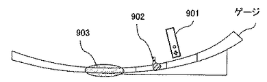
従来より、いわゆるゴルフゲームにおいて、ワイヤレスのコントローラ自体を振り上げて、振り下ろす操作を行うことで、仮想ゲーム空間内のゴルフクラブを動作(ゴルフスイング)させて楽しむゴルフゲームが開示されている(例えば、非特許文献1)。当該ゴルフゲームでは、スイングを行う際の操作内容として、以下のような流れとなっている。まず、画面には、図58に示すようなゲージが表示されている。当該ゲージには、リモコンカーソル901、クラブヘッドカーソル902、インパクトゾーン903が表示されている。そして、プレイヤは、コントローラのAボタンを押しながら当該コントローラを振り上げる。すると、この動きに連動して画面内のリモコンカーソル901がゲージに沿って移動する(図58では右方向に移動)。これに併せて、クラブヘッドカーソル902がリモコンカーソル901を追うように移動する。その後、クラブヘッドカーソル902がリモコンカーソル901に追いついて重なると、クラブヘッドカーソル902は反転して元の位置に戻っていく。そして、このクラブヘッドカーソル902がインパクトゾーン903の範囲内に戻ってきたときに、プレイヤがコントローラを振り下ろすことで、ゴルフのショット動作を行うことができる。
Conventionally, in a so-called golf game, a golf game that is enjoyed by operating a golf club in a virtual game space (golf swing) by performing an operation of swinging up and down the wireless controller itself (for example, golf swing) is disclosed (for example, Non-patent document 1). In the golf game, the flow of operations when swinging is as follows. First, a gauge as shown in FIG. 58 is displayed on the screen. On the gauge, a
しかしながら、上述したようなゲーム装置においては、以下に示す問題点があった。上記のゴルフゲームにおいては、コントローラの持ち方、振り上げる方向は、予め定められた内容に沿っていることを前提としている。(換言すれば、コントローラの持ち方、振り上げる方向は固定された内容である。)そして、この予め定められた内容に沿った動きが行われることを前提として、上記インパクトゾーン903におけるショットの判定処理が実行されている。しかし、コントローラの持ち方や振り上げる方向については、プレイヤによっての個人差がある。そのため、プレイヤによっては、同じような動作を行っているつもりでも、上記の予め定められた内容に沿った動作となっていない場合もあり、その結果、ショットの認識が行われなかったり、逆に、ショットの誤認識が発生したりするという問題があった。
However, the game apparatus as described above has the following problems. In the golf game described above, it is assumed that the controller is held and the direction in which it is raised is in accordance with predetermined contents. (In other words, the way the controller is held and the direction in which it is raised is a fixed content.) Then, on the premise that the movement according to the predetermined content is performed, the shot determination in the
それ故に、本発明の目的は、ゴルフゲームのショットの判定等において、誤判定や誤認識をより軽減できるゲームプログラム及びゲーム装置を提供することである。 SUMMARY OF THE INVENTION Therefore, an object of the present invention is to provide a game program and a game apparatus that can further reduce misjudgment and misrecognition in the determination of golf game shots.
本発明は、上記の課題を解決するために、以下の構成を採用した。なお、括弧内の参照符号および補足説明等は、本発明の理解を助けるために後述する実施形態との対応関係の一例を示したものであって、本発明を何ら限定するものではない。 The present invention employs the following configuration in order to solve the above problems. Note that the reference numerals in parentheses, supplementary explanations, and the like are examples of the correspondence with the embodiments described later in order to help understanding of the present invention, and do not limit the present invention.
第1の発明は、ユーザが操作する入力装置の姿勢または動きを検出する所定の検出手段から取得する姿勢動き情報に基づいて、仮想空間内のオブジェクトを移動させるゲーム装置のコンピュータに実行させるゲームプログラムであって、コンピュータを、姿勢動き情報取得手段(S2)と、姿勢算出手段(S31)と、基準平面設定手段(S32)と、処理手段(S17)として機能させる。姿勢動き情報取得手段は、検出手段で検出された姿勢動き情報を取得する。姿勢算出手段は、姿勢動き情報に基づいて入力装置の姿勢を算出する。基準平面設定手段は、所定のタイミングで、姿勢動き情報に基づいて所定の平面を基準平面として実空間内に仮想的に設定する。処理手段は、基準平面に対する入力装置の姿勢に応じた所定の処理を実行する。 The first invention is a game program that is executed by a computer of a game device that moves an object in a virtual space based on posture movement information acquired from predetermined detection means for detecting the posture or movement of an input device operated by a user. The computer is caused to function as posture motion information acquisition means (S2), posture calculation means (S31), reference plane setting means (S32), and processing means (S17). The posture movement information acquisition unit acquires the posture movement information detected by the detection unit. The posture calculation means calculates the posture of the input device based on the posture motion information. The reference plane setting means virtually sets the predetermined plane as a reference plane in the real space based on the posture movement information at a predetermined timing. The processing means executes a predetermined process corresponding to the attitude of the input device with respect to the reference plane.
第1の発明によれば、プレイヤの操作の誤認識や誤判定を軽減することが可能となる。 According to the first aspect, it is possible to reduce misrecognition and misjudgment of the player's operation.
第2の発明は、第1の発明において、所定の検出手段は、入力装置に備えられている所定の動きセンサである。 In a second aspect based on the first aspect, the predetermined detecting means is a predetermined motion sensor provided in the input device.
第2の発明によれば、入力装置の姿勢をより正確に算出することが可能となる。 According to the second invention, the attitude of the input device can be calculated more accurately.
第3の発明は、第1の発明において、基準平面設定手段は、姿勢算出手段で算出された入力装置の姿勢に基づいて基準平面を設定する。 In a third aspect based on the first aspect, the reference plane setting means sets the reference plane based on the attitude of the input device calculated by the attitude calculation means.
第3の発明によれば、プレイヤが構えている入力装置の姿勢に基づき基準平面を設定するため、プレイヤの操作の誤認識や誤判定を更に軽減することが可能となる。 According to the third aspect, since the reference plane is set based on the attitude of the input device held by the player, it is possible to further reduce misrecognition and misjudgment of the player's operation.
第4の発明は、第3の発明において、基準平面設定手段は、ユーザが入力装置を操作した時の姿勢に基づいて基準平面を設定する。 In a fourth aspect based on the third aspect, the reference plane setting means sets the reference plane based on the posture when the user operates the input device.
第4の発明によれば、ユーザに任意のタイミングで基準平面の設定操作を行わせることができる。 According to the fourth aspect of the invention, it is possible to cause the user to perform a reference plane setting operation at an arbitrary timing.
第5の発明は、第3の発明において、ゲームプログラムは、コンピュータを、角度算出手段と、判定手段として更に機能させる。角度算出手段は、入力装置の姿勢と基準平面とのなす角度を算出する。判定手段は、入力装置の姿勢と基準平面とのなす角度が所定の条件を満たしたか否かを判定する。そして、処理手段は、判定手段において所定の条件を満たしたと判定された時に、所定の処理を実行する。 In a fifth aspect based on the third aspect, the game program causes the computer to further function as angle calculation means and determination means. The angle calculation means calculates an angle formed between the attitude of the input device and the reference plane. The determination unit determines whether or not an angle formed between the attitude of the input device and the reference plane satisfies a predetermined condition. The processing means executes a predetermined process when the determination means determines that the predetermined condition is satisfied.
第6の発明は、第5の発明において、判定手段は、角度算出手段で算出された角度に基づいて、入力装置の姿勢と基準平面とが水平になったか否かを判定する。 In a sixth aspect based on the fifth aspect, the determining means determines whether the attitude of the input device and the reference plane are horizontal based on the angle calculated by the angle calculating means.
第7の発明は、第5の発明において、ゲームプログラムは、判定手段によって入力装置の姿勢と基準平面ととのなす角度が所定の条件を満たしたと判定されるまで、姿勢動き情報取得手段と、姿勢算出手段と、角度算出手段と、判定手段による処理を繰り返し実行する。 According to a seventh aspect based on the fifth aspect, the game program, until the determination means determines that the angle formed between the posture of the input device and the reference plane satisfies a predetermined condition, The processing by the posture calculation unit, the angle calculation unit, and the determination unit is repeatedly executed.
第8の発明は、第7の発明において、判定手段は、角度算出手段で算出された角度に基づいて、入力装置の姿勢と基準平面とのなす角度の符号が反転したか否かを判定する。 In an eighth aspect based on the seventh aspect, the determining means determines whether or not the sign of the angle formed by the attitude of the input device and the reference plane is inverted based on the angle calculated by the angle calculating means. .
第5乃至第8の発明によれば、例えばゴルフスイングのような動作をプレイヤに行わせる際に、プレイヤの意図した操作をより正確にゲーム処理に反映させることが可能となる。 According to the fifth to eighth inventions, for example, when the player performs an action such as a golf swing, the operation intended by the player can be more accurately reflected in the game process.
第9の発明は、第8の発明において、入力装置には、それぞれ直交する3軸が定義されている。そして、基準平面設定手段は、姿勢算出手段で算出された入力装置の姿勢において、定義されている3軸のうちの所定の2軸方向それぞれにかかる姿勢に基づいて基準平面を設定する。 In a ninth aspect based on the eighth aspect, the input device defines three orthogonal axes. Then, the reference plane setting unit sets the reference plane based on the postures in the predetermined two-axis directions among the three defined axes in the posture of the input device calculated by the posture calculation unit.
第10の発明は、第9の発明において、基準平面設定手段は、所定の2軸方向それぞれの姿勢に基づき、基準平面を設定するための2つの平面を算出する候補平面算出手段(S41、S43)を含む。そして、基準平面設定手段は、候補平面算出手段で算出された2つの平面に基づいて基準平面を設定する。 According to a tenth aspect, in the ninth aspect, the reference plane setting means calculates candidate plane calculation means (S41, S43) for calculating two planes for setting the reference plane based on respective postures in two predetermined biaxial directions. )including. The reference plane setting means sets the reference plane based on the two planes calculated by the candidate plane calculation means.
第9乃至第10の発明によれば、多角的な視点で基準平面を算出することができる。 According to the ninth to tenth aspects, the reference plane can be calculated from various viewpoints.
第11の発明は、第10の発明において、候補平面算出手段は、定義されている3軸のうちの所定の1軸と重力方向とを含む平面を2つの平面のうちの1つとして算出する。 In an eleventh aspect based on the tenth aspect, the candidate plane calculating means calculates a plane including a predetermined one of the three defined axes and the direction of gravity as one of the two planes. .
第12の発明は、第11の発明において、候補平面算出手段は、入力装置の長手方向の軸として定義されている軸と重力方向とを含む平面を2つの平面のうちの1つとして算出する。 In a twelfth aspect based on the eleventh aspect, the candidate plane calculating means calculates a plane including the axis defined as the longitudinal axis of the input device and the gravity direction as one of the two planes. .
第13の発明は、第10の発明において、候補平面算出手段は、入力装置の上下方向の軸として定義されている軸と重力方向とを含む平面を2つの平面のうちの1つとして算出する。 In a thirteenth aspect based on the tenth aspect, the candidate plane calculating means calculates a plane including the axis defined as the vertical axis of the input device and the direction of gravity as one of the two planes. .
第14の発明は、第10の発明において、候補平面算出手段は、入力装置の長手方向の軸として定義されている軸を重力方向に向けるような回転を入力装置の上下方向の軸として定義されている軸に加えることで算出される仮想軸と重力方向とを含む平面を2つの平面のうちの1つとして算出する。 In a fourteenth aspect based on the tenth aspect, the candidate plane calculating means is defined as a vertical axis of the input device that rotates the axis defined as the longitudinal axis of the input device in the direction of gravity. A plane including the virtual axis and the direction of gravity calculated by adding to the axis is calculated as one of the two planes.
第15の発明は、第10の発明において、基準平面設定手段は、候補平面算出手段が算出した2つの平面に対して、それぞれ所定の条件に基づく重み付けを行い、当該2つの平面の加重平均となる面を算出し、基準平面として設定する。 In a fifteenth aspect based on the tenth aspect, the reference plane setting means weights the two planes calculated by the candidate plane calculation means based on predetermined conditions, and calculates a weighted average of the two planes. Is calculated and set as a reference plane.
第16の発明は、第15の発明において、基準平面設定手段は、候補平面算出手段が算出した2つの平面のうち、直前に設定された基準平面により近い位置にある平面に対して、より重く重み付けを行う。 In a sixteenth aspect based on the fifteenth aspect, the reference plane setting means is heavier than the plane that is closer to the reference plane set immediately before, among the two planes calculated by the candidate plane calculation means. Perform weighting.
第17の発明は、第15の発明において、基準平面設定手段は、候補平面算出手段が算出した2つの平面のうち、重力方向からより遠い位置となる軸に基づいて算出された平面に対して、より重く重み付けを行う。 According to a seventeenth aspect, in the fifteenth aspect, the reference plane setting unit is configured to calculate a plane calculated based on an axis that is farther from the direction of gravity among the two planes calculated by the candidate plane calculation unit. Weigh more heavily.
第11乃至第17の発明によれば、2つの平面を用いた多角的な視点で基準平面を算出することができ、コントローラの持ち方の違いによって、基準平面を算出するための計算が不安定となることを回避することができる。 According to the eleventh to seventeenth aspects, the reference plane can be calculated from various viewpoints using two planes, and the calculation for calculating the reference plane is unstable due to the difference in how the controller is held. Can be avoided.
第18の発明は、第9の発明において、基準平面設定手段は、入力装置に定義されている所定の2軸方向の軸のうち、重力方向からより遠い位置にある軸を算出用軸として選択し、当該算出用軸にかかる姿勢に基づいて基準平面を設定する。 In an eighteenth aspect based on the ninth aspect, the reference plane setting means selects, as a calculation axis, an axis farther from the gravitational direction among predetermined two axial directions defined in the input device. Then, the reference plane is set based on the posture applied to the calculation axis.
第19の発明は、第18の発明において、基準平面設定手段は、算出用軸に基づいて算出用軸平面を設定する。そして、基準平面設定手段は、当該算出用軸平面に基づいて基準平面を設定する。 In a nineteenth aspect based on the eighteenth aspect, the reference plane setting means sets the calculation axis plane based on the calculation axis. The reference plane setting means sets the reference plane based on the calculation axial plane.
第20の発明は、第19の発明において、基準平面設定手段は、直前に設定された基準平面である旧基準平面、および、算出用軸平面に基づいて基準平面を設定する。 In a twentieth aspect based on the nineteenth aspect, the reference plane setting means sets the reference plane based on the old reference plane which is the reference plane set immediately before and the calculation axis plane.
第21の発明は、第20の発明において、基準平面設定手段は、旧基準平面、および、算出用軸平面のそれぞれに対して所定の条件に基づく重み付けを行い、当該2つの平面の加重平均となる面を算出し、基準平面として設定する。 In a twenty-first aspect based on the twentieth aspect, the reference plane setting means weights each of the old reference plane and the calculation axis plane based on a predetermined condition, and calculates a weighted average of the two planes. Is calculated and set as a reference plane.
第22の発明は、第21の発明において、基準平面設定手段は、旧基準平面に対して、より重く重み付けを行う。 In a twenty-second aspect based on the twenty-first aspect, the reference plane setting means weights the old reference plane more heavily.
第23の発明は、第21の発明において、基準平面設定手段は、算出用軸が重力方向から遠い位置にあるほど、より重く重み付けを行う。 In a twenty-third aspect based on the twenty-first aspect, the reference plane setting means weights more heavily as the calculation axis is located farther from the direction of gravity.
第18乃至第23の発明によれば、重力方向からより遠い位置にある軸に基づいて基準平面を設定するため、プレイヤに違和感を感じさせないような基準平面を設定することができる。 According to the eighteenth to twenty-third aspects, since the reference plane is set based on the axis farther from the direction of gravity, it is possible to set the reference plane that does not make the player feel uncomfortable.
第24の発明は、第10の発明において、基準平面設定手段は、候補平面算出手段が算出した2つの平面のうち、直前に設定された基準平面である旧基準平面により近い方の平面に基づいて基準平面を設定する。 In a twenty-fourth aspect based on the tenth aspect, the reference plane setting means is based on a plane closer to the old reference plane which is the reference plane set immediately before, out of the two planes calculated by the candidate plane calculation means. To set the reference plane.
第25の発明は、第24の発明において、基準平面設定手段は、旧基準平面により近い方の平面、および、当該旧基準平面に対して、それぞれ所定の条件に基づく重み付けを行い、当該2つの平面の加重平均となる面を算出し、基準平面として設定する。 In a twenty-fifth aspect based on the twenty-fourth aspect, the reference plane setting means weights the plane closer to the old reference plane and the old reference plane based on predetermined conditions, respectively, A plane that is a weighted average of the planes is calculated and set as a reference plane.
第26の発明は、第25の発明において、基準平面設定手段は、旧基準平面に対して、より重く重み付けを行う。 In a twenty-sixth aspect based on the twenty-fifth aspect, the reference plane setting means weights the old reference plane more heavily.
第24乃至第26の発明によれば、直前に算出された基準平面をより信頼して新たな基準平面の設定を行うため、プレイヤに違和感を感じさせないような基準平面を設定することができる。 According to the twenty-fourth to twenty-sixth aspects, since a new reference plane is set with more confidence of the reference plane calculated immediately before, it is possible to set a reference plane that does not make the player feel uncomfortable.
第27の発明は、ユーザが操作する入力装置の姿勢または動きを検出する所定の検出手段から取得する姿勢動き情報に基づいて、仮想空間内のオブジェクトを移動させるゲーム装置のコンピュータに実行させるゲームプログラムであって、コンピュータを、姿勢動き情報取得手段(S2)と、姿勢算出手段(S31)と、姿勢補正値算出手段と、処理手段(S17)として機能させる。姿勢動き情報取得手段は、検出手段で検出された姿勢動き情報を取得する。姿勢算出手段は、姿勢動き情報に基づいて入力装置の姿勢を算出する。姿勢補正値算出手段は、所定のタイミングで、姿勢動き情報に基づいて入力装置の姿勢の補正値を算出する。処理手段は、実空間内に仮想的に設定された所定の基準平面に対する入力装置の姿勢を補正値で補正した姿勢に応じて所定の処理を実行する。 According to a twenty-seventh aspect of the present invention, there is provided a game program that is executed by a computer of a game device that moves an object in a virtual space based on posture movement information acquired from a predetermined detection unit that detects the posture or movement of an input device operated by a user. Then, the computer is caused to function as posture motion information acquisition means (S2), posture calculation means (S31), posture correction value calculation means, and processing means (S17). The posture movement information acquisition unit acquires the posture movement information detected by the detection unit. The posture calculation means calculates the posture of the input device based on the posture motion information. The posture correction value calculating means calculates the posture correction value of the input device based on the posture motion information at a predetermined timing. The processing means executes predetermined processing according to an attitude obtained by correcting the attitude of the input device with respect to a predetermined reference plane virtually set in the real space with a correction value.
第27の発明によれば、第1の発明と同様の結果を得ることができる。 According to the twenty-seventh aspect, the same result as in the first aspect can be obtained.
第28の発明は、ユーザが操作する入力装置の姿勢または動きを検出する所定の検出手段から取得する姿勢動き情報に基づいて、仮想空間内のオブジェクトを移動させるゲーム装置であって、姿勢動き情報取得手段(10)と、姿勢算出手段(10)と、基準平面設定手段(10)と、処理手段(10)とを備える。姿勢動き情報取得手段は、検出手段で検出された姿勢動き情報を取得する。姿勢算出手段は、姿勢動き情報に基づいて入力装置の姿勢を算出する。基準平面設定手段は、所定のタイミングで、姿勢動き情報に基づいて所定の平面を基準平面として実空間内に仮想的に設定する。処理手段は、基準平面に対する入力装置の姿勢に応じた所定の処理を実行する。 A twenty-eighth aspect of the present invention is a game device for moving an object in a virtual space based on posture movement information acquired from predetermined detection means for detecting the posture or movement of an input device operated by a user, the posture movement information An acquisition means (10), an attitude calculation means (10), a reference plane setting means (10), and a processing means (10) are provided. The posture movement information acquisition unit acquires the posture movement information detected by the detection unit. The posture calculation means calculates the posture of the input device based on the posture motion information. The reference plane setting means virtually sets the predetermined plane as a reference plane in the real space based on the posture movement information at a predetermined timing. The processing means executes a predetermined process corresponding to the attitude of the input device with respect to the reference plane.
第29の発明は、ユーザが操作する入力装置の姿勢または動きを検出する所定の検出手段から取得する姿勢動き情報に基づいて、仮想空間内のオブジェクトを移動させるゲーム装置であって、姿勢動き情報取得手段(10)と、姿勢算出手段(10)と、姿勢補正値算出手段(10)と、処理手段(10)とを備える。姿勢動き情報取得手段と、検出手段で検出された姿勢動き情報を取得する。姿勢算出手段は、姿勢動き情報に基づいて入力装置の姿勢を算出する。姿勢補正値算出手段は、所定のタイミングで、姿勢動き情報に基づいて入力装置の姿勢の補正値を算出する。処理手段は、実空間内に仮想的に設定された所定の基準平面に対する入力装置の姿勢を補正値で補正した姿勢に応じて所定の処理を実行する。 A twenty-ninth aspect of the present invention is a game device for moving an object in a virtual space based on posture movement information acquired from predetermined detection means for detecting the posture or movement of an input device operated by a user, the posture movement information An acquisition means (10), an attitude calculation means (10), an attitude correction value calculation means (10), and a processing means (10) are provided. Posture movement information acquisition means and posture movement information detected by the detection means are acquired. The posture calculation means calculates the posture of the input device based on the posture motion information. The posture correction value calculating means calculates the posture correction value of the input device based on the posture motion information at a predetermined timing. The processing means executes predetermined processing according to an attitude obtained by correcting the attitude of the input device with respect to a predetermined reference plane virtually set in the real space with a correction value.
第28乃至第29の発明によれば、第1の発明と同様の結果を得ることができる。 According to the twenty-eighth to twenty-ninth aspects, the same result as in the first aspect can be obtained.
本発明によれば、動き情報から算出される入力装置の姿勢等に基づいて基準平面を設定し、これに基づいた処理を実行できるため、例えば、ゴルフゲームにおけるショットの判定等の処理において、誤認識や誤判定の発生を防ぐことができる。 According to the present invention, it is possible to set a reference plane based on the posture of the input device calculated from the motion information and execute a process based on the reference plane. Generation of recognition and erroneous determination can be prevented.
[ゲームシステムの全体構成]
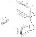
図1を参照して、本発明の一実施形態に係る姿勢算出装置の一例であるゲーム装置を含むゲームシステム1について説明する。図1は、ゲームシステム1の外観図である。以下、据置型のゲーム装置を一例にして、本実施形態のゲーム装置およびゲームプログラムについて説明する。図1において、ゲームシステム1は、テレビジョン受像器(以下、単に「テレビ」と記載する)2、ゲーム装置3、光ディスク4、入力装置8、およびマーカ部6を含む。本システムは、入力装置8を用いたゲーム操作に基づいてゲーム装置3でゲーム処理を実行するものである。
[Overall configuration of game system]
With reference to FIG. 1, a
ゲーム装置3には、当該ゲーム装置3に対して交換可能に用いられる情報記憶媒体の一例である光ディスク4が脱着可能に挿入される。光ディスク4には、ゲーム装置3において実行されるためのゲームプログラムが記憶されている。ゲーム装置3の前面には光ディスク4の挿入口が設けられている。ゲーム装置3は、挿入口に挿入された光ディスク4に記憶されているゲームプログラムを読み出して実行することによってゲーム処理を実行する。
An
ゲーム装置3には、表示装置の一例であるテレビ2が接続コードを介して接続される。テレビ2は、ゲーム装置3において実行されるゲーム処理の結果得られるゲーム画像を表示する。また、テレビ2の画面の周辺(図1では画面の上側)には、マーカ部6が設置される。マーカ部6は、その両端に2つのマーカ6Rおよび6Lを備えている。マーカ6R(マーカ6Lも同様)は、具体的には1以上の赤外LEDであり、テレビ2の前方に向かって赤外光を出力する。マーカ部6はゲーム装置3に接続されており、ゲーム装置3はマーカ部6が備える各赤外LEDの点灯を制御することが可能である。
A
入力装置8は、自機に対して行われた操作の内容を示す操作データをゲーム装置3に与えるものである。本実施形態では、入力装置8はコントローラ5とジャイロセンサユニット7とを含む。詳細は後述するが、入力装置8は、コントローラ5に対してジャイロセンサユニット7が着脱可能に接続されている構成である。コントローラ5とゲーム装置3とは無線通信によって接続される。本実施形態では、コントローラ5とゲーム装置3との間の無線通信には例えばBluetooth(ブルートゥース)(登録商標)の技術が用いられる。なお、他の実施形態においてはコントローラ5とゲーム装置3とは有線で接続されてもよい。
The
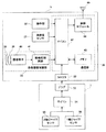
[ゲーム装置3の内部構成]
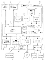
次に、図2を参照して、ゲーム装置3の内部構成について説明する。図2は、ゲーム装置3の構成を示すブロック図である。ゲーム装置3は、CPU10、システムLSI11、外部メインメモリ12、ROM/RTC13、ディスクドライブ14、およびAV−IC15等を有する。
[Internal configuration of game device 3]
Next, the internal configuration of the
CPU10は、光ディスク4に記憶されたゲームプログラムを実行することによってゲーム処理を実行するものであり、ゲームプロセッサとして機能する。CPU10は、システムLSI11に接続される。システムLSI11には、CPU10の他、外部メインメモリ12、ROM/RTC13、ディスクドライブ14およびAV−IC15が接続される。システムLSI11は、それに接続される各構成要素間のデータ転送の制御、表示すべき画像の生成、外部装置からのデータの取得等の処理を行う。システムLSI11の内部構成については後述する。揮発性の外部メインメモリ12は、光ディスク4から読み出されたゲームプログラムや、フラッシュメモリ17から読み出されたゲームプログラム等のプログラムを記憶したり、各種データを記憶したりするものであり、CPU10のワーク領域やバッファ領域として用いられる。ROM/RTC13は、ゲーム装置3の起動用のプログラムが組み込まれるROM(いわゆるブートROM)と、時間をカウントするクロック回路(RTC:Real Time Clock)とを有する。ディスクドライブ14は、光ディスク4からプログラムデータやテクスチャデータ等を読み出し、後述する内部メインメモリ11eまたは外部メインメモリ12に読み出したデータを書き込む。
The
また、システムLSI11には、入出力プロセッサ(I/Oプロセッサ)11a、GPU(Graphics Processor Unit)11b、DSP(Digital Signal Processor)11c、VRAM11d、および内部メインメモリ11eが設けられる。図示は省略するが、これらの構成要素11a〜11eは内部バスによって互いに接続される。
Further, the
GPU11bは、描画手段の一部を形成し、CPU10からのグラフィクスコマンド(作画命令)に従って画像を生成する。VRAM11dは、GPU11bがグラフィクスコマンドを実行するために必要なデータ(ポリゴンデータやテクスチャデータ等のデータ)を記憶する。画像が生成される際には、GPU11bは、VRAM11dに記憶されたデータを用いて画像データを作成する。
The
DSP11cは、オーディオプロセッサとして機能し、内部メインメモリ11eや外部メインメモリ12に記憶されるサウンドデータや音波形(音色)データを用いて、音声データを生成する。
The
上述のように生成された画像データおよび音声データは、AV−IC15によって読み出される。AV−IC15は、読み出した画像データをAVコネクタ16を介してテレビ2に出力するとともに、読み出した音声データを、テレビ2に内蔵されるスピーカ2aに出力する。これによって、画像がテレビ2に表示されるとともに音がスピーカ2aから出力される。
The image data and audio data generated as described above are read out by the AV-
入出力プロセッサ11aは、それに接続される構成要素との間でデータの送受信を実行したり、外部装置からのデータのダウンロードを実行したりする。入出力プロセッサ11aは、フラッシュメモリ17、無線通信モジュール18、無線コントローラモジュール19、拡張コネクタ20、およびメモリカード用コネクタ21に接続される。無線通信モジュール18にはアンテナ22が接続され、無線コントローラモジュール19にはアンテナ23が接続される。
The input /
入出力プロセッサ11aは、無線通信モジュール18およびアンテナ22を介してネットワークに接続し、ネットワークに接続される他のゲーム装置や各種サーバと通信することができる。入出力プロセッサ11aは、定期的にフラッシュメモリ17にアクセスし、ネットワークへ送信する必要があるデータの有無を検出し、当該データが有る場合には、無線通信モジュール18およびアンテナ22を介してネットワークに送信する。また、入出力プロセッサ11aは、他のゲーム装置から送信されてくるデータやダウンロードサーバからダウンロードしたデータを、ネットワーク、アンテナ22および無線通信モジュール18を介して受信し、受信したデータをフラッシュメモリ17に記憶する。CPU10はゲームプログラムを実行することにより、フラッシュメモリ17に記憶されたデータを読み出してゲームプログラムで利用する。フラッシュメモリ17には、ゲーム装置3と他のゲーム装置や各種サーバとの間で送受信されるデータの他、ゲーム装置3を利用してプレイしたゲームのセーブデータ(ゲームの結果データまたは途中データ)が記憶されてもよい。
The input /
また、入出力プロセッサ11aは、コントローラ5から送信される操作データをアンテナ23および無線コントローラモジュール19を介して受信し、内部メインメモリ11eまたは外部メインメモリ12のバッファ領域に記憶(一時記憶)する。
The input /
さらに、入出力プロセッサ11aには、拡張コネクタ20およびメモリカード用コネクタ21が接続される。拡張コネクタ20は、USBやSCSIのようなインターフェースのためのコネクタであり、外部記憶媒体のようなメディアを接続したり、他のコントローラのような周辺機器を接続したり、有線の通信用コネクタを接続することによって無線通信モジュール18に替えてネットワークとの通信を行ったりすることができる。メモリカード用コネクタ21は、メモリカードのような外部記憶媒体を接続するためのコネクタである。例えば、入出力プロセッサ11aは、拡張コネクタ20やメモリカード用コネクタ21を介して外部記憶媒体にアクセスし、外部記憶媒体にデータを保存したり、外部記憶媒体からデータを読み出したりすることができる。
Further, an
ゲーム装置3には、電源ボタン24、リセットボタン25、およびイジェクトボタン26が設けられる。電源ボタン24およびリセットボタン25は、システムLSI11に接続される。電源ボタン24がオンされると、ゲーム装置3の各構成要素に対して、図示しないACアダプタを経て電源が供給される。リセットボタン25が押されると、システムLSI11は、ゲーム装置3の起動プログラムを再起動する。イジェクトボタン26は、ディスクドライブ14に接続される。イジェクトボタン26が押されると、ディスクドライブ14から光ディスク4が排出される。
The
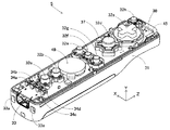
[入力装置8の構成]
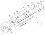
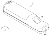
次に、図3〜図6を参照して、入力装置8について説明する。図3は、入力装置8の外観構成を示す斜視図である。図4は、コントローラ5の外観構成を示す斜視図である。図3は、コントローラ5の上側後方から見た斜視図であり、図4は、コントローラ5を下側前方から見た斜視図である。
[Configuration of Input Device 8]
Next, the
図3および図4において、コントローラ5は、例えばプラスチック成型によって形成されたハウジング31を有している。ハウジング31は、その前後方向(図3に示すZ軸方向)を長手方向とした略直方体形状を有しており、全体として大人や子供の片手で把持可能な大きさである。プレイヤは、コントローラ5に設けられたボタンを押下すること、および、コントローラ5自体を動かしてその位置や姿勢を変えることによってゲーム操作を行うことができる。
3 and 4, the
ハウジング31には、複数の操作ボタンが設けられる。図3に示すように、ハウジング31の上面には、十字ボタン32a、1番ボタン32b、2番ボタン32c、Aボタン32d、マイナスボタン32e、ホームボタン32f、プラスボタン32g、および電源ボタン32hが設けられる。本明細書では、これらのボタン32a〜32hが設けられるハウジング31の上面を「ボタン面」と呼ぶことがある。一方、図4に示すように、ハウジング31の下面には凹部が形成されており、当該凹部の後面側傾斜面にはBボタン32iが設けられる。これらの各操作ボタン32a〜32iには、ゲーム装置3が実行するゲームプログラムに応じた機能が適宜割り当てられる。また、電源ボタン32hは遠隔からゲーム装置3本体の電源をオン/オフするためのものである。ホームボタン32fおよび電源ボタン32hは、その上面がハウジング31の上面に埋没している。これによって、プレイヤがホームボタン32fまたは電源ボタン32hを誤って押下することを防止することができる。
The
ハウジング31の後面にはコネクタ33が設けられている。コネクタ33は、コントローラ5に他の機器(例えば、ジャイロセンサユニット7や他のコントローラ)を接続するために利用される。また、ハウジング31の後面におけるコネクタ33の両側には、上記他の機器が容易に離脱することを防止するために係止穴33aが設けられている。
A
ハウジング31上面の後方には複数(図3では4つ)のLED34a〜34dが設けられる。ここで、コントローラ5には、他のメインコントローラと区別するためにコントローラ種別(番号)が付与される。各LED34a〜34dは、コントローラ5に現在設定されている上記コントローラ種別をプレイヤに通知したり、コントローラ5の電池残量をプレイヤに通知したりする等の目的で用いられる。具体的には、コントローラ5を用いてゲーム操作が行われる際、上記コントローラ種別に応じて複数のLED34a〜34dのいずれか1つが点灯する。
A plurality (four in FIG. 3) of
また、コントローラ5は撮像情報演算部35(図6)を有しており、図4に示すように、ハウジング31前面には撮像情報演算部35の光入射面35aが設けられる。光入射面35aは、マーカ6Rおよび6Lからの赤外光を少なくとも透過する材質で構成される。
Further, the
ハウジング31上面における1番ボタン32bとホームボタン32fとの間には、コントローラ5に内蔵されるスピーカ49(図5)からの音を外部に放出するための音抜き孔31aが形成されている。
Between the
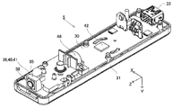
次に、図5および図6を参照して、コントローラ5の内部構造について説明する。図5および図6は、コントローラ5の内部構造を示す図である。なお、図5は、コントローラ5の上筐体(ハウジング31の一部)を外した状態を示す斜視図である。図6は、コントローラ5の下筐体(ハウジング31の一部)を外した状態を示す斜視図である。図6に示す斜視図は、図5に示す基板30を裏面から見た斜視図となっている。
Next, the internal structure of the
図5において、ハウジング31の内部には基板30が固設されており、当該基板30の上主面上に各操作ボタン32a〜32h、各LED34a〜34d、加速度センサ37、アンテナ45、およびスピーカ49等が設けられる。これらは、基板30等に形成された配線(図示せず)によってマイクロコンピュータ(Micro Computer:マイコン)42(図6参照)に接続される。本実施形態では、加速度センサ37は、X軸方向に関してコントローラ5の中心からずれた位置に配置されている。これによって、コントローラ5をZ軸回りに回転させたときのコントローラ5の動きが算出しやすくなる。また、加速度センサ37は、長手方向(Z軸方向)に関してコントローラ5の中心よりも前方に配置されている。また、無線モジュール44(図6)およびアンテナ45によって、コントローラ5がワイヤレスコントローラとして機能する。
In FIG. 5, a
一方、図6において、基板30の下主面上の前端縁に撮像情報演算部35が設けられる。撮像情報演算部35は、コントローラ5の前方から順に赤外線フィルタ38、レンズ39、撮像素子40、および画像処理回路41を備えている。これらの部材38〜41はそれぞれ基板30の下主面に取り付けられる。
On the other hand, in FIG. 6, an imaging
さらに、基板30の下主面上には、上記マイコン42およびバイブレータ48が設けられている。バイブレータ48は、例えば振動モータやソレノイドであり、基板30等に形成された配線によってマイコン42と接続される。マイコン42の指示によりバイブレータ48が作動することによってコントローラ5に振動が発生する。これによって、コントローラ5を把持しているプレイヤの手にその振動が伝達される、いわゆる振動対応ゲームを実現することができる。本実施形態では、バイブレータ48は、ハウジング31のやや前方寄りに配置される。つまり、バイブレータ48がコントローラ5の中心よりも端側に配置することによって、バイブレータ48の振動によりコントローラ5全体を大きく振動させることができる。また、コネクタ33は、基板30の下主面上の後端縁に取り付けられる。なお、図5および図6に示す他、コントローラ5は、マイコン42の基本クロックを生成する水晶振動子、スピーカ49に音声信号を出力するアンプ等を備えている。
Further, the
また、ジャイロセンサユニット7は、3軸回りの角速度を検知するジャイロセンサ(図7に示すジャイロセンサ55および56)を有する。ジャイロセンサユニット7は、コントローラ5のコネクタ33に着脱可能に装着される。ジャイロセンサユニット7の前端(図3に示すZ軸正方向側の端部)には、コネクタ33に接続可能なプラグ(図7に示すプラグ53)が設けられる。さらに、プラグ53の両側にはフック(図示せず)が設けられる。ジャイロセンサユニット7がコントローラ5に対して装着される状態では、プラグ53がコネクタ33に接続されるとともに、上記フックがコントローラ5の係止穴33aに係止する。これによって、コントローラ5とジャイロセンサユニット7とがしっかりと固定される。また、ジャイロセンサユニット7は側面(図3に示すX軸方向の面)にボタン51を有している。ボタン51は、それを押下すれば上記フックの係止穴33aに対する係止状態を解除することができるように構成されている。したがって、ボタン51を押下しながらプラグ53をコネクタ33から抜くことによって、ジャイロセンサユニット7をコントローラ5から離脱することができる。
Further, the
また、ジャイロセンサユニット7の後端には、上記コネクタ33と同形状のコネクタが設けられる。したがって、コントローラ5(のコネクタ33)に対して装着可能な他の機器は、ジャイロセンサユニット7のコネクタに対しても装着可能である。なお、図3においては、当該コネクタに対してカバー52が着脱可能に装着されている。
A connector having the same shape as the
なお、図3〜図6に示したコントローラ5およびジャイロセンサユニット7の形状や、各操作ボタンの形状、加速度センサやバイブレータの数および設置位置等は単なる一例に過ぎず、他の形状、数、および設置位置であっても、本発明を実現することができる。また、本実施形態では、撮像手段による撮像方向はZ軸正方向であるが、撮像方向はいずれの方向であってもよい。すなわち、コントローラ5における撮像情報演算部35の位置(撮像情報演算部35の光入射面35a)は、ハウジング31の前面でなくてもよく、ハウジング31の外部から光を取り入れることができれば他の面に設けられてもかまわない。
The shapes of the
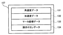
図7は、入力装置8(コントローラ5およびジャイロセンサユニット7)の構成を示すブロック図である。コントローラ5は、操作部32(各操作ボタン32a〜32i)、コネクタ33、撮像情報演算部35、通信部36、および加速度センサ37を備えている。コントローラ5は、自機に対して行われた操作内容を示すデータを操作データとしてゲーム装置3へ送信するものである。
FIG. 7 is a block diagram showing a configuration of the input device 8 (the
操作部32は、上述した各操作ボタン32a〜32iを含み、各操作ボタン32a〜32iに対する入力状態(各操作ボタン32a〜32iが押下されたか否か)を示す操作ボタンデータを通信部36のマイコン42へ出力する。
The
撮像情報演算部35は、撮像手段が撮像した画像データを解析してその中で輝度が高い領域を判別してその領域の重心位置やサイズなどを算出するためのシステムである。撮像情報演算部35は、例えば最大200フレーム/秒程度のサンプリング周期を有するので、比較的高速なコントローラ5の動きでも追跡して解析することができる。
The imaging
撮像情報演算部35は、赤外線フィルタ38、レンズ39、撮像素子40、および画像処理回路41を含んでいる。赤外線フィルタ38は、コントローラ5の前方から入射する光から赤外線のみを通過させる。レンズ39は、赤外線フィルタ38を透過した赤外線を集光して撮像素子40へ入射させる。撮像素子40は、例えばCMOSセンサやあるいはCCDセンサのような固体撮像素子であり、レンズ39が集光した赤外線を受光して画像信号を出力する。ここで、テレビ2の表示画面近傍に配置されるマーカ部6のマーカ6Rおよび6Lは、テレビ2の前方に向かって赤外光を出力する赤外LEDで構成される。したがって、赤外線フィルタ38を設けることによって、撮像素子40は、赤外線フィルタ38を通過した赤外線だけを受光して画像データを生成するので、マーカ6Rおよび6Lの画像をより正確に撮像することができる。以下では、撮像素子40によって撮像された画像を撮像画像と呼ぶ。撮像素子40によって生成された画像データは、画像処理回路41で処理される。画像処理回路41は、撮像画像内における撮像対象(マーカ6Rおよび6L)の位置を算出する。画像処理回路41は、算出された位置を示す座標を通信部36のマイコン42へ出力する。この座標のデータは、マイコン42によって操作データとしてゲーム装置3に送信される。以下では、上記座標を「マーカ座標」と呼ぶ。マーカ座標はコントローラ5自体の向き(傾斜角度)や位置に対応して変化するので、ゲーム装置3はこのマーカ座標を用いてコントローラ5の向きや位置を算出することができる。
The imaging
なお、他の実施形態においては、コントローラ5は画像処理回路41を備えていない構成であってもよく、撮像画像自体がコントローラ5からゲーム装置3へ送信されてもよい。このとき、ゲーム装置3は、画像処理回路41と同様の機能を有する回路あるいはプログラムを有しており、上記マーカ座標を算出するようにしてもよい。
In other embodiments, the
加速度センサ37は、コントローラ5の加速度(重力加速度を含む)を検出する、すなわち、コントローラ5に加わる力(重力を含む)を検出する。加速度センサ37は、当該加速度センサ37の検出部に加わっている加速度のうち、センシング軸方向に沿った直線方向の加速度(直線加速度)の値を検出する。例えば、2軸以上の多軸加速度センサの場合には、加速度センサの検出部に加わっている加速度として、各軸に沿った成分の加速度をそれぞれ検出する。例えば、3軸または2軸の加速度センサは、アナログ・デバイセズ株式会社(Analog Devices, Inc.)またはSTマイクロエレクトロニクス社(STMicroelectronics N.V.)から入手可能である種類のものでもよい。なお、加速度センサ37は、例えば静電容量式の加速度センサであるとするが、他の方式の加速度センサを用いるようにしてもよい。
The
本実施形態では、加速度センサ37は、コントローラ5を基準とした上下方向(図3に示すY軸方向)、左右方向(図3に示すX軸方向)および前後方向(図3に示すZ軸方向)の3軸方向に関してそれぞれ直線加速度を検出する。加速度センサ37は、各軸に沿った直線方向に関する加速度を検出するものであるため、加速度センサ37からの出力は3軸それぞれの直線加速度の値を表すものとなる。すなわち、検出された加速度は、入力装置8(コントローラ5)を基準に設定されるXYZ座標系(コントローラ座標系)における3次元のベクトル(ax,ay,az)として表される。以下では、加速度センサ37によって検出される3軸に関する各加速度値を各成分とするベクトルを加速度ベクトルと呼ぶ。
In the present embodiment, the
加速度センサ37が検出した加速度を示すデータ(加速度データ)は、通信部36へ出力される。なお、加速度センサ37が検出した加速度は、コントローラ5自体の向き(傾斜角度)や動きに対応して変化するので、ゲーム装置3は加速度データを用いてコントローラ5の向きや動きを算出することができる。本実施形態では、ゲーム装置3は、加速度データに基づいてコントローラ5の姿勢を判断する。
Data indicating the acceleration detected by the acceleration sensor 37 (acceleration data) is output to the
加速度センサ37が検出した加速度(加速度ベクトル)を示すデータ(加速度データ)は、通信部36へ出力される。本実施形態において、加速度センサ37は、コントローラ5の傾斜角度を判断するためのデータを出力するセンサとして用いられる。
Data (acceleration data) indicating the acceleration (acceleration vector) detected by the
なお、加速度センサ37から出力される加速度の信号に基づいて、ゲーム装置3のプロセッサ(例えばCPU10)またはコントローラ5のプロセッサ(例えばマイコン42)等のコンピュータが処理を行うことによって、コントローラ5に関するさらなる情報を推測または算出(判定)することができることは、当業者であれば本明細書の説明から容易に理解できるであろう。例えば、加速度センサ37を搭載するコントローラ5が静止状態であることを前提としてコンピュータ側の処理が実行される場合(すなわち、加速度センサによって検出される加速度が重力加速度のみであるとして処理が実行される場合)、コントローラ5が現実に静止状態であれば、検出された加速度に基づいてコントローラ5の姿勢が重力方向に対して傾いているか否かまたはどの程度傾いているかを知ることができる。具体的には、加速度センサ37の検出軸が鉛直下方向を向いている状態を基準としたとき、1G(重力加速度)がかかっているか否かによって、コントローラ5が基準に対して傾いているか否かを知ることができるし、その大きさによって基準に対してどの程度傾いているかも知ることができる。また、多軸の加速度センサ37の場合には、さらに各軸の加速度の信号に対して処理を施すことによって、重力方向に対してコントローラ5がどの程度傾いているかをより詳細に知ることができる。この場合において、プロセッサは、加速度センサ37からの出力に基づいてコントローラ5の傾斜角度を算出してもよいし、当該傾斜角度を算出せずに、コントローラ5の傾斜方向を算出するようにしてもよい。このように、加速度センサ37をプロセッサと組み合わせて用いることによって、コントローラ5の傾斜角度または姿勢を判定することができる。
In addition, based on the acceleration signal output from the
一方、コントローラ5が動的な状態(コントローラ5が動かされている状態)であることを前提とする場合には、加速度センサ37は重力加速度に加えてコントローラ5の動きに応じた加速度を検出するので、検出された加速度から重力加速度の成分を所定の処理により除去することによってコントローラ5の動き方向を知ることができる。また、コントローラ5が動的な状態であることを前提とする場合であっても、検出された加速度から、加速度センサの動きに応じた加速度の成分を所定の処理により除去することによって、重力方向に対するコントローラ5の傾きを知ることが可能である。なお、他の実施例では、加速度センサ37は、内蔵の加速度検出手段で検出された加速度信号をマイコン42に出力する前に当該加速度信号に対して所定の処理を行うための、組込み式の処理装置または他の種類の専用の処理装置を備えていてもよい。組込み式または専用の処理装置は、例えば、加速度センサ37が静的な加速度(例えば、重力加速度)を検出するために用いられる場合、加速度信号を傾斜角(あるいは、他の好ましいパラメータ)に変換するものであってもよい。
On the other hand, when it is assumed that the
通信部36は、マイコン42、メモリ43、無線モジュール44、およびアンテナ45を含んでいる。マイコン42は、処理を行う際にメモリ43を記憶領域として用いながら、マイコン42が取得したデータをゲーム装置3へ無線送信する無線モジュール44を制御する。また、マイコン42はコネクタ33に接続されている。ジャイロセンサユニット7から送信されてくるデータは、コネクタ33を介してマイコン42に入力される。以下、ジャイロセンサユニット7の構成について説明する。
The
ジャイロセンサユニット7は、プラグ53、マイコン54、2軸ジャイロセンサ55、および1軸ジャイロセンサ56を備えている。上述のように、ジャイロセンサユニット7は、3軸(本実施形態では、XYZ軸)周りの角速度を検出し、検出した角速度を示すデータ(角速度データ)をコントローラ5へ送信する。
The
2軸ジャイロセンサ55は、X軸周りの角速度およびY軸周りの(単位時間あたりの)角速度を検出する。また、1軸ジャイロセンサ56は、Z軸周りの(単位時間あたりの)角速度を検出する。なお、本明細書では、コントローラ5の撮像方向(Z軸正方向)を基準として、XYZ軸周りの回転方向を、それぞれ、ロール方向、ピッチ方向、ヨー方向と呼ぶ。すなわち、2軸ジャイロセンサ55は、ロール方向(X軸周りの回転方向)およびピッチ方向(Y軸周りの回転方向)の角速度を検出し、1軸ジャイロセンサ56は、ヨー方向(Z軸周りの回転方向)の角速度を検出する。
The
なお、本実施形態では、3軸回りの角速度を検出するために、2軸ジャイロセンサ55と1軸ジャイロセンサ56とを用いる構成としたが、他の実施形態においては、3軸回りの角速度を検出することができればよく、用いるジャイロセンサの数および組み合わせはどのようなものであってもよい。
In this embodiment, the 2-
また、本実施形態では、後述する姿勢算出処理における計算を容易にする目的で、各ジャイロセンサ55および56が角速度を検出する3つの軸は、加速度センサ37が加速度を検出する3つの軸(XYZ軸)と一致するように設定される。ただし、他の実施形態においては、各ジャイロセンサ56および57が角速度を検出する3つの軸と、加速度センサ37が加速度を検出する3つの軸とは一致しなくてもよい。
Further, in the present embodiment, for the purpose of facilitating the calculation in the posture calculation process described later, the three axes where the
各ジャイロセンサ56および57で検出された角速度を示すデータは、マイコン54に出力される。したがって、マイコン54には、XYZ軸の3軸回りの角度速度を示すデータが入力されることになる。マイコン54は、上記3軸回りの角速度を示すデータを角速度データとしてプラグ53を介してコントローラ5へ送信する。なお、マイコン54からコントローラ5への送信は所定の周期毎に逐次行われるが、ゲームの処理は1/60秒を単位として(1フレーム時間として)行われることが一般的であるので、この時間以下の周期で送信を行うことが好ましい。
Data indicating the angular velocity detected by each of the
コントローラ5の説明に戻り、操作部32、撮像情報演算部35、および加速度センサ37からマイコン42へ出力されたデータ、ならびに、ジャイロセンサユニット7からマイコン42へ送信されてきたデータは、一時的にメモリ43に格納される。これらのデータは、上記操作データとしてゲーム装置3へ送信される。すなわち、マイコン42は、ゲーム装置3の無線コントローラモジュール19への送信タイミングが到来すると、メモリ43に格納されている操作データを無線モジュール44へ出力する。無線モジュール44は、例えばBluetooth(ブルートゥース)(登録商標)の技術を用いて、所定周波数の搬送波を操作データで変調し、その微弱電波信号をアンテナ45から放射する。つまり、操作データは、無線モジュール44で微弱電波信号に変調されてコントローラ5から送信される。微弱電波信号はゲーム装置3側の無線コントローラモジュール19で受信される。受信された微弱電波信号について復調や復号を行うことによって、ゲーム装置3は操作データを取得することができる。そして、ゲーム装置3のCPU10は、取得した操作データとゲームプログラムとに基づいて、ゲーム処理を行う。なお、通信部36から無線コントローラモジュール19への無線送信は所定の周期毎に逐次行われるが、ゲームの処理は1/60秒を単位として(1フレーム時間として)行われることが一般的であるので、この時間以下の周期で送信を行うことが好ましい。コントローラ5の通信部36は、例えば1/200秒に1回の割合で各操作データをゲーム装置3の無線コントローラモジュール19へ出力する。
Returning to the description of the
上記コントローラ5を用いることによって、プレイヤは、各操作ボタンを押下する従来の一般的なゲーム操作に加えて、コントローラ5を任意の傾斜角度に傾ける操作を行うことができる。その他、上記コントローラ5によれば、プレイヤは、コントローラ5によって画面上の任意の位置を指示する操作、および、コントローラ5自体を動かす操作を行うこともできる。
By using the
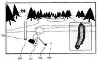
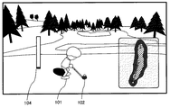
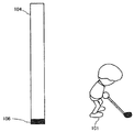
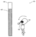
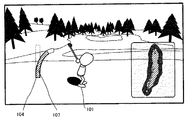
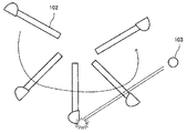
次に、本実施形態で想定するゲームの概要について説明する。図8は、本実施形態で想定するゲームの画面の一例である。本実施形態で想定するゲームはゴルフゲームである。図8において、3次元仮想空間内に構築されたゴルフコースがゲーム画面として表示されており、ゲーム画面には、ゴルフクラブ102を持ったプレイヤオブジェクト101、ゴルフボールオブジェクト103(以下、単にボールと呼ぶ)、パワーゲージ104等が表示されている。また、パワーゲージ104の中には、スイングバー106が表示されている。
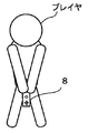
Next, an outline of the game assumed in this embodiment will be described. FIG. 8 is an example of a game screen assumed in the present embodiment. The game assumed in this embodiment is a golf game. In FIG. 8, a golf course constructed in a three-dimensional virtual space is displayed as a game screen, and a
次に、本ゲームにおけるプレイヤの操作方法について説明する。本ゲームは、上記入力装置8をゴルフクラブに見立てて操作する。例えば、プレイヤは、図9に示すように、入力装置8の前面(光入射面35aがある面)を下方向に向けて両手で把持する。そして、プレイヤは、ゴルフのスイングを模した動作を行う。このスイング動作に連動して、仮想空間内のプレイヤオブジェクト101もスイング動作を行い、これに伴ってゴルフクラブ102も移動する。つまり、プレイヤの腕を振る動作が、プレイヤオブジェクト101のスイング動作に反映されることになる。
Next, a player operation method in this game will be described. In this game, the
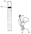
上記の操作についてより具体的に説明すると、まず、ボールを打つ前(スイングを開始する前)のプレイヤオブジェクトの初期状態としては、図8のように、ボール103から少し離れた場所に位置している。この状態のときに、プレイヤが上記のようにスイング動作を行うことで、「素振り」ができる。そして、ボールを打つときは、プレイヤはAボタン32dを押す。すると、図10に示すように、プレイヤオブジェクト101が前進してボール103に近づく。そして、Aボタン32dを押したまま、プレイヤが上記スイング動作を行うことで、ゴルフクラブ102をボール103に当てて、ボール103を飛ばす、つまり、ショットを行うことができる。このように、本ゲームでは、プレイヤが入力装置8を把持し、Aボタン32dを押さずにゴルフのスイング動作を行うことで「素振り」を行い、Aボタン32dを押しながらスイング動作を行うことでボール103を打って飛ばすことで、実際のゴルフに近いプレイ感覚のゴルフゲームを楽しむことができる。
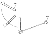
The above operation will be described in more detail. First, as an initial state of the player object before hitting the ball (before starting the swing), as shown in FIG. Yes. In this state, the player can swing as described above by performing the swing motion as described above. When hitting the ball, the player presses the
また、本ゲームでは、Aボタン32dを押していない状態で、Bボタン32iを押すことで「構え直し」という操作を行うことができる。当該「構え直し」は、現実世界におけるプレイヤの正面方向を定義するための操作である(ゴルフでいう、「アドレス」の姿勢をとることに近い概念となる)。これは、ジャイロセンサでは姿勢の「変化」しか分からないため、プレイヤにBボタン32iを押してもらうことで、正面方向を定めるものである。そして、この操作で定義された正面方向を基準として、本ゴルフゲームにかかる各種処理が実行されることになる。
Further, in this game, an operation “reposition” can be performed by pressing the
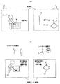
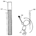
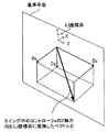
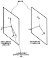
より具体的には、Bボタン32iを押したときの入力装置8の姿勢に基づき、実空間においてプレイヤの正面方向に伸びるような仮想的な平面を算出し、「基準平面」として設定するような処理を実行する。図11に、当該基準平面の概念を示す模式図を示す。図11(a)に示すように、基準平面は、実空間におけるプレイヤ自身の正面方向に伸びるような(仮想上の)平面である。同時に、図11(b)に示すように、プレイヤの位置の対応する仮想空間内の位置、すなわち、プレイヤオブジェクト101の正面方向に伸びるような平面に相当する。そして、当該基準平面と、スイング中の入力装置8の姿勢とを比較することで、スイング角度(プレイヤが入力装置8を振りかぶっている量)などのパラメータの算出が実行されたり、また、インパクトが発生したか否か(ゴルフクラブ102とボール103が当たったか否か)の判定等が実行される。より具体的には、スイング角度(後述の振りかぶり角度)について、基準平面の位置を0°として捉え、ボールを飛ばす側を正の値、振りかぶる側を負の値の角度として考える(本実施形態では、+180°〜−180°という範囲で考える)。そして、例えば、スイング角度が負の値から正の値に変化したときに、入力装置8が基準平面と接触、あるいは通過した(インパクトが発生した)という判定を行う。
More specifically, based on the attitude of the
しかし、一旦正面方向(基準平面)を決めたとしても、その後、プレイヤが入力装置8を振っているうちに、ジャイロセンサの計測誤差や計算誤差の蓄積によって、上記定義した正面方向と、その時々における入力装置8の姿勢との関係が不正確になり得る。また、プレイヤ自身が向きを変えることによって、上記正面方向と定義した方向が、プレイヤの目から見た正面方向ではなくなってしまうこともあり得る。その結果、入力装置8を振っているうちに、現実世界のプレイヤが今、仮想ゲーム空間においてどちらの方向を向いて立っているか分からない(仮想ゲーム空間における正面方向を向いているのかどうかわからない)という問題が発生する。結果的に、プレイヤは「正面」を向いてスイングしているつもりでも、ゲーム処理上は、正面を向いていない状態でスイングしているような扱いで処理され得る。そのために、定期的にBボタン32iを押すことで、正面方向(基準平面)を再設定する必要がある。また、例えば、入力装置8を一旦振りかぶった後、振り下ろさずにそのままの状態を維持したまま、ある程度時間が経過したような場合も、上記計算誤差の蓄積による影響が発生する可能性がある。そのため、上記Bボタン32iを押したときの入力装置8の姿勢(アドレス時の姿勢)と、現在の入力装置8の姿勢との差異が大きい状態であり、入力装置8に動きが発生していない状態がある程度の時間経過したような場合も、上記正面方向(基準平面)を再設定することが好ましい。
However, even if the front direction (reference plane) is once determined, the front direction defined above and sometimes from time to time as the measurement error and calculation error of the gyro sensor are accumulated while the player is waving the
ここで、本実施形態では、Bボタン32iが押されたときの入力装置8の持ち方の違いによって、正面方向を算出するための計算が不安定となることを回避するために、後述するような処理を行うことで、多角的な基準で正面方向(基準平面)を定めている。
Here, in this embodiment, in order to avoid that the calculation for calculating the front direction becomes unstable due to the difference in how the
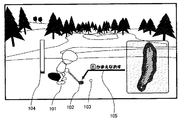
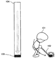
更に、本実施形態では、基準平面の再設定の必要性を推定して、適当だと思われるタイミングで、図12に示すような、上記「構え直し」操作をプレイヤに促すメッセージ105(以下、構え直しガイドと呼ぶ)の表示を行うという処理も実行している。 Furthermore, in the present embodiment, the necessity of resetting the reference plane is estimated, and the message 105 (hereinafter, referred to as the following) prompting the player to perform the above-mentioned “reposition” operation as shown in FIG. A process of displaying a repositioning guide) is also executed.
次に、上記ゲーム画面に表示されているパワーゲージ104に関して説明する。パワーゲージ104は、棒状の形状で表示されており、ゴルフクラブ102の振りかぶり量(プレイヤにとっては、打球パワーの目安となる情報)と、手首の捻り度合い(Z軸回りの角度)という2種類の情報を表示するものである。まず、振りかぶり量については、ゲージ内のスイングバー106の位置で示される。このスイングバー106は、振りかぶり量に応じてゲージ内を上下する。例えば、図13に示すように、基本姿勢(アドレスの姿勢)の状態では、スイングバー106はパワーゲージ104の一番下に位置している。その後、ゴルフクラブ102がボール103にインパクトするまでの間は、スイングバー106は振りかぶり量に応じてリアルタイムにパワーゲージ104内を上下する。
Next, the
具体的には、ゴルフクラブ102(実世界では、入力装置8)を振り上げると、図14に示すように、スイングバー106は上方に移動する。振りかぶり量が大きいほど、より上に移動する。その後、クラブを振り下げると、スイングバー106は下方に移動する。そして、インパクト時には、図15に示すように、スイングバー106はパワーゲージ104の一番下に位置することになる。また、インパクトの時点で、打球のパワーが決定する。打球パワーが決定すると(すなわち、インパクトすると)、スイングバー106の表示は消えて、代わりに、図16に示すような、打球パワーを示すパワーバー107が、決定した打球パワーを示す長さまで下から伸びていく。そして、決定した打球パワーに対応する長さまで伸びると、図17に示すように、パワーバー107の伸びはそこで停止し、それ以上は伸びない。
Specifically, when the golf club 102 (in the real world, the input device 8) is swung up, the
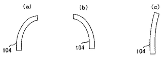
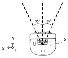
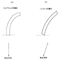
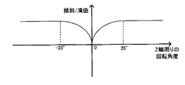
次に、手首の捻り角度(Z軸回りの回転角度)については、図18に示すように、パワーゲージ104の形状自体を湾曲させることで表現している。例えば、手首を右側(時計回り)に捻っていれば、図19(a)に示すように、パワーゲージ104の形状が右に湾曲した形状となる。また、手首を左方向(反時計回り)に捻っていれば、図19(b)示すように、左に湾曲した形状となす。また、捻り具合が大きい程、湾曲具合も大きくなり、捻り具合が小さければ、図19(c)にように、湾曲具合も小さくなる。なお、本実施形態では、捻り角度(Z軸周りの回転角度)の最大値は、図20に示すように、入力装置8のY軸を中心として、左右それぞれ35°(−35°〜+35°)までとして扱う(これ以上の角度の捻りは、35°の捻りとして扱う)。また、捻り角度については、本実施形態では、構え直し操作を行ったときの角度を0°として、右側への捻りを正の値、左側の捻りを負の値として算出されるものとする。
Next, as shown in FIG. 18, the wrist twist angle (rotation angle around the Z axis) is expressed by curving the shape of the
このようにして、本実施形態のパワーゲージ104では、振りかぶり量と手首の捻り角度という異なる2つの要素を1つのパワーゲージでまとめて表示している。
In this way, in the
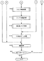
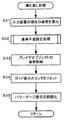
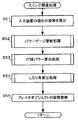
次に、本実施形態にかかる処理のうち、特徴的な処理について説明する。本実施形態において特徴的な処理は、大きく以下の3つに大別される。
(1)ショット関連処理
(2)パワーゲージ関連処理
(3)かまえなおしガイド処理
Next, a characteristic process among the processes according to the present embodiment will be described. The characteristic processing in this embodiment is roughly divided into the following three types.
(1) Shot-related processing (2) Power gauge-related processing (3) Rework guide processing
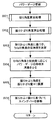
まず、上記(1)ショット関連については、更に以下のような3つの処理に大別される。
(1−1)基準平面算出処理
(1−2)振り下ろし動作反映処理
(1−3)バックスピン処理
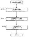
まず、(1−1)基準平面算出処理は、上述のように、Bボタン32iが押されたときに上記基準平面を算出・設定するための処理である。上記のように、コントローラの持ち方の違いによって、基準平面を算出するための計算が不安定となることを回避するために、多角的な視点で基準平面を算出する処理である。
First, the above (1) shot relation is further roughly divided into the following three processes.
(1-1) Reference plane calculation process (1-2) Downward motion reflection process (1-3) Backspin process First, (1-1) Reference plane calculation process is performed by pressing the
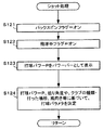
次に、(1−2)振り下ろし動作反映処理は、クラブを振りかぶったときの上記スイングバー106の高さをベースにショットパワーを算出する処理である。具体的には、一旦クラブを振り上げ、その後、ゆっくりと下ろした場合は、スイングバー106の降下にともない弱いショットパワーが算出される。一方、一旦クラブを振り上げ、ある程度勢いよく振り下ろした場合は、振りかぶったときのスイングバー106の高さに近いショットパワーが算出される。また、一旦クラブを振り上げた後、さらに強く振り下ろした場合は、それ以上のショットパワーが算出される。つまり、振り下ろし時の際の動き方をショットパワーに反映させるための処理である。スイング中の振り下ろしにかかる動作をショットに反映させるための処理である。具体的には、上記スイングバー106の移動に関して、一旦クラブを振り上げ、その後、ゆっくりと下ろしたときは、スイングバー106もその動きに追従して下がるが、一旦振り上げて、勢いよく振り下ろした場合、ほぼ振り上げたときのパワーでショットすることができる。つまり、振り下ろし時の際の動き方をショットパワーに反映させる処理である。
Next, (1-2) the swing-down action reflecting process is a process of calculating shot power based on the height of the
次に、(1−3)バックスピン処理については、本実施形態では、スイングしてインパクトしたときに、図21に示すように、最後まで振り切らずに、図22に示すようにボール103のある場所で止めるようなスイング(インパクトの位置で急ブレーキをかけて止めるようなスイング)を行うことで、打球にバックスピンをかけることができる。そして、このような、途中で急ブレーキをかけるようなスイング(制動力がかかったスイング)を検出し、そのときの動きをバックスピンに反映させる処理が、当該(1−3)バックスピン処理である。
Next, regarding (1-3) backspin processing, in this embodiment, when swinging and impacting, as shown in FIG. 21, the
次に、上記(2)パワーゲージ関連処理では、上記のような、振りかぶりの量(スイング角度)と、手首の捻り(Z軸まわりの回転角度)とを算出して、それぞれをパワーゲージ104の表示に反映させるための処理が実行される。 Next, in the above (2) power gauge-related processing, the amount of swinging-up (swing angle) and the twist of the wrist (rotation angle around the Z axis) as described above are calculated. Processing for reflecting in the display is executed.
次に、(3)かまえなおしガイド処理とは、本実施形態では、上記のように、定期的にBボタン32iの押下による「構え直し」(基準平面の再設定)が必要となるが、この基準平面の再設定の必要性を推定して、適当だと思われるタイミングで上記構え直しガイド105の表示を行う処理である。
Next, (3) Re-feeding guide processing, in this embodiment, as described above, it is necessary to periodically “reposition” (resetting the reference plane) by pressing the
次に、上記の各処理の概要について説明する。
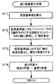
[基準平面設定処理の概要]
まず、上記(1)ショット関連処理の(1−1)基準平面設定処理にかかる処理の概要を説明する。本処理は、上述したように、Bボタン32iが押されたときに基準平面(正面方向)を定義する処理である。そして、Bボタン32iが押されたときの、プレイヤの入力装置8の持ち方の違いによる計算結果の不安定さを回避するために、本実施形態では、以下のような処理を行っている。
Next, an overview of each of the above processes will be described.
[Overview of reference plane setting process]
First, the outline of the process related to the (1-1) reference plane setting process of the (1) shot related process will be described. As described above, this process is a process of defining a reference plane (front direction) when the
まず、現在の入力装置8の姿勢に基づいて、(入力装置8のローカル座標系における)Z軸方向と重力方向を含む平面を算出する。以下、この平面を、第1の候補面と呼ぶ。
First, based on the current posture of the
次に、Z軸正方向を重力方向に向けるような回転を、Y軸に対して加えることで、Y'軸を算出する。これは、仮想的に入力装置8を真下に向け直し、この状態のY軸方向を求めたものである。そして、当該Y'軸と重力方向とを含む平面を算出する。以下、この平面を第2の候補面と呼ぶ。
Next, the Y ′ axis is calculated by applying rotation to the Y axis so that the positive direction of the Z axis is directed to the direction of gravity. This is obtained by virtually turning the
なお、Y軸をそのまま使うのではなく、Y'軸を算出するのは、以下の理由による。一般的に、ゴルフスイングの構えを取った場合、入力装置8は真下を向いた姿勢よりも、斜めになった姿勢(Z軸を持ち上げるような姿勢)となることが多いと考えられる。このZ軸の持ち上がりの姿勢回転に引きずられて、Y軸方向がプレイヤの正面方向からずれているケースが多い。そのため、Y軸をそのまま使うよりも、入力装置8を一旦真下に向けたと仮定したY'軸を用いるほうが、ゴルフゲームの処理を行う際には、より良い算出結果が得られると考えられるためである。そのため、ゲーム処理の内容によっては、Y'軸を使わず、Y軸をそのまま用いてもよい。
The Y ′ axis is calculated instead of using the Y axis as it is for the following reason. In general, when a posture of a golf swing is taken, it is considered that the
そして、上記2つの候補面と、その時点において算出済みである基準平面(つまり、直近に算出された基準平面)とに基づいて、新たな基準平面を算出する。当該新たな基準平面の算出については、例えば以下のような処理を用いる。まず、上記2つの候補面をブレンドすることで新たは基準平面を求めるという方法がある。このとき、現在の基準平面に近いほうに位置する候補面をより信頼するような重み付けを加えて、2つの平面をブレンドするような処理を行う。 Then, a new reference plane is calculated based on the two candidate planes and the reference plane that has been calculated at that time (that is, the reference plane calculated most recently). For example, the following processing is used for calculating the new reference plane. First, there is a method in which a new reference plane is obtained by blending the above two candidate planes. At this time, processing is performed such that the two planes are blended by applying a weight that makes the candidate plane located closer to the current reference plane more reliable.
例えば、入力装置8と基準平面、および、上記2つの候補面との関係が、図23のような関係とする。図23は、入力装置8のZ軸負方向から見た場合を想定した模式図である。この場合、第1の候補面と現在の基準平面との成す角をθA、第2の候補面と現在の基準平面との成す角をθBとすると、例えば、以下のような式で新たな基準平面を算出する。
重みa=1-cos(θB/2)
重みb=1-cos(θA/2)
比率a=重みa / (重みa+重みb)
比率b=重みb / (重みa+重みb)
新たな基準平面=比率a×第1の候補面+比率b×第2の候補面 ・・・式1
なお、上記の式において、重みaは、第2の候補面が現在の基準平面からずれているほど大きくなり、重みbは、第1の候補面が現在の基準平面からずれているほど大きくなる。
For example, the relationship between the
Weight a = 1-cos (θB / 2)
Weight b = 1-cos (θA / 2)
Ratio a = weight a / (weight a + weight b)
Ratio b = weight b / (weight a + weight b)
New reference plane = ratio a × first candidate plane + ratio b × second
In the above formula, the weight a increases as the second candidate plane deviates from the current reference plane, and the weight b increases as the first candidate plane deviates from the current reference plane. .
また、上記比率aおよび比率bについては、以下のような式を用いて算出してもよい。
重みa=1-cos(θB/2)
重みb=1-cos(θA/2)
Further, the ratio a and the ratio b may be calculated using the following formula.
Weight a = 1-cos (θB / 2)
Weight b = 1-cos (θA / 2)
![]()
![]()
![]()
![]()
新たな基準平面=比率a×第1の候補面+比率b×第2の候補面 New reference plane = ratio a × first candidate plane + ratio b × second candidate plane
なお、上記式1については、現在の基準平面と各候補面との「近さ」に着目したものであるが、この他、各候補面と重力方向とのなす角度に着目した手法を用いても良い。すなわち、上記Z軸方向と重力方向のなす角と、上記Y軸方向(あるいはY'軸方向)と重力方向のなす角とをそれぞれ算出する。そして、算出した角度が大きいほど、上記式1における加重平均の比率(上記比率aおよび比率b)を高めるようにしてもよい。
Note that the
また、別の算出方法として、現在の基準平面により近い方の候補面だけを選び、当該候補面と現在の基準平面とをブレンドすることで新たな基準平面を算出するようにしてもよい。候補面と基準平面との関係が上記図23のような関係であるとすると、例えば、以下のような式で算出する。
新たな基準平面=0.9×現在の基準平面+0.1×選択した候補面・・・式2
なお、上記式2では、加重平均の比率を固定(0.9と0.1)している。この式の場合、現在の基準平面の重み付けが高い、つまり、現在の基準平面の信頼度を高くした式となっている。
As another calculation method, only a candidate plane closer to the current reference plane may be selected, and a new reference plane may be calculated by blending the candidate plane and the current reference plane. Assuming that the relationship between the candidate plane and the reference plane is as shown in FIG. 23, for example, the following calculation is performed.
New reference plane = 0.9 × current reference plane + 0.1 × selected
In
また、上記式2で固定的に設定している加重平均の比率については、固定的にすることに限らない。例えば、上記「現在の基準平面により近い方の候補面」を算出するための用いた軸(Z軸あるいはY'軸)と重力方向との成す角度が大きいほど、上記式3における加重平均の比率を高めるようにしてもよい。
Further, the weighted average ratio that is fixedly set in
また、上記「現在の基準平面により近い方の候補面」の代わりに、上記Z軸と重力方向との成す角と、Y'軸と重力方向との成す角とをそれぞれ算出し、成す角が大きいほうの平面を選択するようにしてもよい。つまり、入力装置8が、ゴルフスイングの構えのように、下に下がった状態であればY'軸を用いて算出された候補面をより信頼し、野球のバッターの構えのように、入力装置8が起き上がっているような状態であれば、Z軸を用いて算出された候補面をより信頼して新たな基準平面を算出するようにしてもよい。
Also, instead of the “candidate surface closer to the current reference plane”, the angle formed by the Z-axis and the gravitational direction and the angle formed by the Y′-axis and the gravitational direction are respectively calculated. The larger plane may be selected. In other words, if the
なお、上記のブレンド方法はあくまで一例であり、これらに限らず、2つの候補平面および現在の基準平面を適切にブレンドできれば、どのような処理方法を用いても良い。 The blending method described above is merely an example, and the present invention is not limited thereto, and any processing method may be used as long as the two candidate planes and the current reference plane can be appropriately blended.
以上のような算出方法を用いることで、基準平面について、複数の方法で算出した候補面が矛盾する場合は信頼度を考慮しつつゆるやかに補正を行い、一致する場合は大胆に大きく補正するという結果を得ることができる。このように、「重力方向」や「現在の基準平面」との関係に注目することで、プレイヤの入力装置8の持ち方の違いによる計算結果の不安定さ、すなわち、ちょっとした持ち方のぶれでプレイヤの意図しない方向に正面方向(基準平面)が設定される、ということを回避している。
その結果、プレイヤの入力装置8の持ち方に応じて基準平面の位置を補正するような処理が行われていることになる。
By using the calculation method as described above, if the candidate planes calculated by a plurality of methods are inconsistent, the reference plane is corrected gently considering the reliability, and if they match, the correction is made boldly and greatly. The result can be obtained. In this way, by paying attention to the relationship with the “gravity direction” and the “current reference plane”, the calculation result is unstable due to the difference in how the player holds the
As a result, processing for correcting the position of the reference plane according to how the player holds the
[振り下ろし動作反映処理の概要]
次に、上記(1−2)の振り下ろし動作反映処理の処理概要を説明する。本処理は、振り下ろし時の動きを打球パワーに反映させるための処理であり、例えば、プレイヤが大きく振りかぶり、強く振り下ろせば打球パワーが大きく算出され、弱く、あるいはゆっくりと振り下ろせば、それに連れて打球パワーも低下させて算出するような処理である。具体的には、プレイヤがコントローラ振りかぶることで、スイングバー106がパワーゲージ104の一番上(打球パワーの目安として、100%の打球パワーが期待できるような状態)まで上がった場合を想定する。この状態から、プレイヤが素早く振り下ろすようにスイングを行えば、ほぼ100%のパワーを打球パワーに反映する。一方、スイングバー106がパワーゲージ104の一番上まで上がっている状態から、プレイヤが思い直して(例えば、これでは強すぎる、と考えた場合等)、例えばパワーゲージ104の75%くらいの位置(パワーゲージ104の一番下から3/4程度の距離の位置)まで、ゆっくりと入力装置8(ゴルフクラブ102)を下げて(この動きに連動して、スイングバー106も下に下がる)、その位置からスイングした場合は、上述したような100%のパワーではなく、思い直して下ろした後の75%付近のパワーを打球パワーに反映する。このような、振り下ろし動作にかかる内容を打球パワーに反映させるための処理である。
[Overview of swing-down action reflection processing]
Next, an outline of the above-described (1-2) swing-down action reflection process will be described. This process is a process for reflecting the movement at the time of swinging down to the hitting ball power. For example, if the player swings large and swings down strongly, the hitting ball power is calculated to be large. In this process, the hitting power is also reduced. Specifically, it is assumed that the
上記のような処理内容を実現するために、本実施形態では、以下のような処理を実行している。まず、スイングバー106に対応する振りかぶり量Hが算出される。振りかぶり量Hの算出については、後述の「パワーゲージ関連処理」についての説明等において説明するが、プレイヤが入力装置8を振りかぶっている量(スイングの角度)が振りかぶり量(つまり、パワーゲージ104内におけるスイングバー106の位置)として算出される。更に、本処理では、この振りかぶり量(スイングバー106)に追従するような追従量T(Tは0.0〜1.0)という値を算出する。当該追従量Tは、以下のような式で算出される。
H<Tのときは
T=T+追従係数Kt×(H−T) ・・・式3
H≧Tのときは、
T=H
上記の式について説明すると、H<Tのとき、というのは、振り下げ動作を行っているときを示し、H≧Tのとき、というのは、主に振り上げ動作を行っているときを示している。そして、振り上げ動作が行われているときは、追従量Tは振りかぶり量Hと同じ値にしておき、振り下げ動作中のみ追従するような値が算出されるようにしている。また、追従係数Ktは、強いスイングのとき(加速度が大きいとき)は追従性を低くし、弱いスイングのとき(加速度が小さいとき)は、追従性を高くするための係数である。当該追従係数Ktは、スイング中の振りの強さを加速度の大きさで捉え、変化させている。具体的には、まず、加速度センサ37から得られる加速度から、重力成分(1.0G)を除去し、更にその絶対値をとったものを「加速度の大きさ」とする。本実施形態では、この絶対値は、0.0G〜1.2Gの範囲内の値になるものとする。そして、この加速度の大きさである0.0G〜1.2Gの値を、0.2〜0.01の範囲内の値に変換して(割り当てて)追従係数Ktとする(つまり、Kt=0.2〜0.01)。
In order to realize the processing contents as described above, the following processing is executed in the present embodiment. First, the swing-up amount H corresponding to the
When H <T, T = T + follow-up coefficient Kt × (HT)
When H ≧ T,
T = H
The above formula will be explained. When H <T, it means that the swing-down operation is performed, and when H ≧ T, it means that the swing-up operation is mainly performed. Yes. When the swing-up operation is performed, the follow-up amount T is set to the same value as the swing-up amount H, and a value that follows only during the swing-down operation is calculated. The follow-up coefficient Kt is a coefficient for lowering the followability when the swing is strong (when acceleration is large) and increasing the followability when the swing is weak (when acceleration is small). The follow-up coefficient Kt is changed by grasping the strength of the swing during the swing by the magnitude of the acceleration. Specifically, first, the gravitational component (1.0 G) is removed from the acceleration obtained from the
このような算出を行うことで、プレイヤが入力装置8を振りがぶった後、速く振り下ろしたとき、あるいは、強く振り下ろしたときほど、追従量Tは、過去の振りかぶり量の内の最大値(以下、最大振りかぶり量と呼ぶ)に近い値が維持されうる。また、ゆっくり振り下ろす、あるいは弱く振り下ろすと、追従量Tは振りかぶり量Hと共に下がっていくことになる。
By performing such a calculation, the follow-up amount T becomes the maximum value of the past swing-up amounts as the player swings down the
なお、上記式3において、(H−T)としているため、振りかぶり量Hと追従量Tの差が大きいときほど、Tの値をより大きく減少させる(追従させる)ことになる。
Since (HT) is used in
また、上記のH≧Tのときは、追従量Tの値は振りかぶり量Hを下限とする。つまり、振り下げの動作中であっても、追従量Tの値は振りかぶり量Hの値を追い越して下がってしまわないようにしている。 Further, when the above H ≧ T, the follow-up amount T has a swing-up amount H as a lower limit. That is, even during the swing-down operation, the value of the follow-up amount T is not overtaken by the value of the swing-up amount H.
ここで、打球のパワーの決定に関して、従来のゴルフゲームでは最大振りかぶり量をスイングパワーとしていたが、本実施形態では、ゴルフクラブ102とボール103がインパクトしたときに最終的な打球のパワー(以下、打球パワーP)が決定される。このときに、上記最大振りかぶり量、あるいは、上記振りかぶり量Hの値をそのまま打球パワーPとして用いるのではなく、上記追従量Tの値を打球パワーPとして用いる。つまり、振りかぶり量Hを補正した値に相当する追従量Tを打球パワーPとして用いる。これにより、上述のような速く振り下ろしたときと、ゆっくり振り下ろしたときの打球パワーPの違いを実現することができる。しかし、本実施形態では、更に、打球パワーPの決定に際して、以下のような処理を行うことで最終的な打球パワーPを決定している。
Here, regarding the determination of the hit ball power, in the conventional golf game, the maximum swinging amount is the swing power. However, in this embodiment, when the
本実施形態では、上記追従量Tに加え、更に、「過剰な振り強さS」という要素を算出する(Sは0.0〜1.0)。これは、例えば「力を込めた強い振り下ろし方」と「力はあまり込めていない軽い振り下ろし方」等のような、スイングにかかる振り下ろしの「強さ」を評価し、打球パワーに反映しようとするものである。上記追従量Tの計算方法、特にスイング中の加速度が大きいときほど追従係数Ktを小さくする計算によって、強く振れば振るほど(加速度が大きいほど)、打球パワーPは大きくなる。しかし、その上限値は振りかぶり量Hの最大値に等しいので、逆に言うと、どんなに強く振ってもそれ以上の打球パワーを出すことはできない。そこで、強く振っても打球パワーP(追従量T)に影響しないような過剰なスイング中の加速度を「過剰な振り強さS」として評価し、改めて打球パワーPに上乗せすることを考える。本実施形態では、この「過剰な振り強さ」を一連のスイング動作を通じて評価する方法として、仮想的にスイング中の加速度を目減りさせて計算してみて打球パワーPがどう変化するかを観察する方法をとる。例えば、上記振りかぶり量Hの状態から振り下ろしたときの「振りおろしの強さ」を100%とした場合に、加速度が2割しか出ていなかったと仮定して(つまり、加速度を8割引いて)上記追従量Tを再計算する。このように加速度を小さく見積もって再計算すると、上記追従量T等の要素もあり、最終的に、例えば、60%〜80%の「振りおろしの強さ」が算出されることが予想される。このように加速度を8割引で計算したにも関わらず、元の「振りおろしの強さ」との差が小さい(再計算結果が80%程度の値)、つまり、あまり元の強さと変化がない場合は、もともとの加速度値が大きすぎると評価することができる。一方、元の「振りおろしの強さ」との差がより大きい(再計算結果が60%程度の値)であれば、加速度的には無駄がなかったと評価することができる。つまり、加速度の目減りに応じて打球パワーPが下がれば加速度的に無駄のないスイング、加速度を目減りさせても打球パワーPがあまり下がらなければ、もともとの加速度値が大きすぎる、即ち、加速度的に過剰なスイングと考える。そこで、この元の「振り下ろしの強さ」と加速度を割り引いて再計算した「振り下ろしの強さ」との算出結果の差を「過剰な振り強さS」として評価する。 In the present embodiment, in addition to the follow-up amount T, an element of “excessive swing strength S” is calculated (S is 0.0 to 1.0). This evaluates the “strength” of swinging down, such as “how to swing down with force” and “lightly swinging down with less force”, and reflects it in the hitting ball power. It is something to try. By the calculation method of the follow-up amount T, particularly by calculating the follow-up coefficient Kt to be smaller as the acceleration during the swing is larger, the hitting power P becomes larger as the player shakes more strongly (the acceleration is greater). However, since the upper limit value is equal to the maximum value of the swing-up amount H, in other words, no more hitting power can be produced no matter how strong the swing is. Therefore, it is considered that an excessive acceleration during swinging that does not affect the hitting ball power P (following amount T) even if it is shaken strongly is evaluated as “excessive swinging strength S” and added to the hitting ball power P again. In the present embodiment, as a method for evaluating this “excessive swing strength” through a series of swing motions, the calculation is performed by virtually reducing the acceleration during the swing, and observing how the hitting power P changes. Take the way. For example, assuming that the “strength of swinging down” when swinging down from the state of swinging amount H is 100%, it is assumed that only 20% of the acceleration is present (that is, the acceleration is discounted by 8). The follow-up amount T is recalculated. Thus, when the acceleration is estimated to be small and recalculated, there are factors such as the follow-up amount T, and it is expected that the “swinging strength” of 60% to 80% is finally calculated. . Although the acceleration is calculated with 8 discounts in this way, the difference from the original “strength of swinging” is small (the recalculation result is about 80%), that is, the original strength and change are not so much. If not, it can be evaluated that the original acceleration value is too large. On the other hand, if the difference from the original “strength of swinging” is larger (the recalculation result is a value of about 60%), it can be evaluated that there was no waste in terms of acceleration. In other words, if the hitting power P decreases according to the decrease in acceleration, the original acceleration value is too large if the hitting power P does not decrease too much even if the hitting power P decreases too much. Think of it as an excessive swing. Therefore, the difference between the calculation result of the original “swinging strength” and the “swinging strength” recalculated by discounting the acceleration is evaluated as “excessive swinging strength S”.
具体的には、以下のような処理を行っている。まず、スイング中の加速度が、実際の2割しか出ていなかったと想定して(加速度を8割差し引いて)、上記追従量Tの算出と同じ計算を行い、その結果を割引追従量T'とする(本実施形態では、T'は0.0〜1.0)。そして、上記追従量Tと割引追従量T'とを比較し、その差をみる。その結果、両者の差が小さい場合は、より力の込められたスイング(加速度的に過剰なスイング)が行われていたとして扱い、両者の差が大きい場合は、実際のスイングの強さは(ゲーム処理上において)適当な強さの振り(加速度的に無駄のないスイング)として扱う。 Specifically, the following processing is performed. First, assuming that the actual acceleration during the swing was only 20% (subtracting 80% of the acceleration), the same calculation as the calculation of the follow-up amount T is performed, and the result is expressed as a discount follow-up amount T ′. (In this embodiment, T ′ is 0.0 to 1.0). Then, the follow-up amount T and the discount follow-up amount T ′ are compared, and the difference is observed. As a result, if the difference between the two is small, it is treated as if a more powerful swing (excessive acceleration swing) was performed, and if the difference between the two is large, the actual swing strength is ( It is treated as a swing of appropriate strength (in a game process) (a swing that is not wasteful in terms of acceleration).
より具体的な算出方法について説明する。本実施形態では、まず、T'/Tを計算する。そして、その算出結果のうち0.6〜0.8の範囲内の値を上記過剰な振り強さS(0.0〜1.0)に割り当てる。そして、当該過剰な振り強さSと追従量Tとを用いて、以下の式で最終的な打球パワーPを算出する。
P=T+係数Ks×S ・・・式4
ここで、係数Ksは、Sの重み付けを示しており、本実施形態では0.25とする。つまり、過剰な振り強さSの25%を追従量Tに上乗せすることで、打球パワーPを決定している(なお、係数Ksの値は、ゲームバランス等を考慮して適宜決められる値である)。
A more specific calculation method will be described. In the present embodiment, first, T ′ / T is calculated. And the value within the range of 0.6-0.8 is allocated to the excessive swing strength S (0.0-1.0) among the calculation results. Then, by using the excessive swing strength S and the follow-up amount T, the final hit ball power P is calculated by the following equation.
P = T + coefficient Ks ×
Here, the coefficient Ks indicates the weighting of S, and is 0.25 in the present embodiment. That is, the ball hitting power P is determined by adding 25% of the excessive swing strength S to the follow-up amount T (note that the value of the coefficient Ks is a value that is appropriately determined in consideration of game balance and the like). is there).
上記のように、追従量T、および、過剰な振り強さSという要素を加味して打球パワーPを算出する処理を行うことで、本実施形態では、振り下ろしのときの動作内容を打球パワーに反映させることが可能となっている。例えば、スイングバー106を100%の度合い(スイングバー106がパワーゲージ104の一番上まで上がった状態)まで振り上げた後、素早く振り下ろせば、ほぼ100%の打球パワーが得られるが、ゆっくり振り下ろせば、それに連れてより低下した打球パワーになるという処理を実現することができる。
As described above, by performing the process of calculating the hitting power P in consideration of the elements of the follow-up amount T and the excessive swing strength S, in this embodiment, the operation content at the time of swinging down is the hitting power. It is possible to reflect on. For example, if the
[バックスピン処理の概要]
次に、上記(1−3)のバックスピンに関する処理の概要について説明する。上記のように、スイングの動作について、最後まで振り切らずに、途中でゴルフクラブを止めるようなスイングを行うことで、打球にバックスピンをかけることができる。このような動きを実現するため、本実施形態では、ゴルフクラブのヘッド部分の「しなり」を想定して利用する。より具体的には、「スイングによって後方にしなり、スイングが止まるとしなりが戻り、場合によっては惰性でさらに前方にしなる」ような「しなり」のモデルを利用する。
[Outline of backspin processing]
Next, the outline of the processing related to backspin (1-3) will be described. As described above, backspin can be applied to the hit ball by performing a swing that stops the golf club halfway without swinging all the way to the end. In order to realize such a movement, in the present embodiment, the golf club head portion is used assuming “bending”. More specifically, a “bending” model such as “becomes backward by a swing, returns when the swing stops, and sometimes further forward by inertia” is used.
上記のようなモデルにおける、スイング中のクラブヘッドのしなりを考えると、普通にスイングした場合、ゴルフクラブを振りあげ、振り下ろし始めてクラブヘッドがボールに当たるまでは、クラブヘッド部分は後方にしなる。そして、上記のようにスイングを急に止めたとき、つまり、制動力がかかったとき、クラブヘッド部分は惰性で前方にしなると考えられる。そこで、本実施形態では、この前方へのしなりの最大値を拾い、バックスピン率に反映するという処理を実行している。つまり、スイング(クラブ)が止まった後、惰性でどこまで前方(ボールが飛ぶ方向)にしなるかを測り、そのしなり具合に応じてバックスピン率(バックスピンの強さ)を設定するという処理を行っている。 Considering the bending of the club head during the swing in the model as described above, when swinging normally, the club head portion is in the rear direction until the golf club swings up and starts to swing down until it hits the ball. When the swing is suddenly stopped as described above, that is, when a braking force is applied, it is considered that the club head portion is inertial and forward. Therefore, in the present embodiment, processing is performed in which the maximum value of the forward bending is picked up and reflected in the backspin rate. In other words, after the swing (club) stops, it measures how far forward (in the direction the ball flies) by inertia, and sets the backspin rate (backspin strength) according to the condition. Is going.
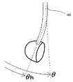
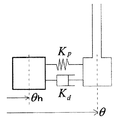
図24に、当該ヘッド部分のしなりの一例を模式的に示す。図24においては、角度θは上記の振りかぶり角度を示す。角度θh(以下、追従角度と呼ぶ)は、しなっているクラブのヘッド部分の角度を示す。そのため、しなり角φは、次の式で算出することができる(図24では、φ<0の状態である)。
φ=θh−θ ・・・式5
そして、当該しなり角φが前方(φ>0)になったときの変化を監視しておき、前方への変化のうちの最大値を拾い、バックスピン率に反映する。
FIG. 24 schematically shows an example of bending of the head portion. In FIG. 24, the angle θ represents the above-described swing angle. The angle θh (hereinafter referred to as the follow-up angle) indicates the angle of the head portion of the club that is bent. Therefore, the bending angle φ can be calculated by the following equation (in FIG. 24, φ <0).
φ = θh−θ
Then, the change when the bending angle φ becomes forward (φ> 0) is monitored, and the maximum value of the forward change is picked up and reflected in the backspin rate.
上記のようなしなりを、「バネ」と「ダンパー」を用いてモデル化したものを図25に示す。図25では、クラブのヘッド部分が、「ばね」Kpと「ダンパー」Kdでクラブの本体部分に接続されているようなモデルを示している。本実施形態では、このようなモデルを用いて、クラブヘッド部分のしなりをシミュレートする。具体的には、まず、以下の式を用いて、ヘッド部分の加速度Aを算出する。
A=−Kp(θh−θ)−Kd(θhd−θd)・・・式6
ここで、変数θhdは、前フレームのθhと現在のフレームとのθhの差分を示す。また、変数θdは、前フレームにおけるθと現在のフレームとのθの差分を示す。また、上記式6の「−Kp(θh−θ)」におけるθhは、前フレームにおける追従角度θhであり、θは現在の振りかぶり角度θである。
FIG. 25 shows a model of the above bend using “spring” and “damper”. FIG. 25 shows a model in which the head portion of the club is connected to the main body portion of the club by “spring” Kp and “damper” Kd. In the present embodiment, such a model is used to simulate the bending of the club head portion. Specifically, first, the acceleration A of the head portion is calculated using the following equation.
A = −Kp (θh−θ) −Kd (θhd−θd)
Here, the variable θhd indicates a difference between θh of the previous frame and the current frame. The variable θd indicates the difference between θ in the previous frame and the current frame. Further, θh in “−Kp (θh−θ)” of the
更に、変数Kp(ばね)およびKd(ダンパー)に関して、本実施形態では、振りかぶり角度θの絶対値に応じて変数KpおよびKdを更新している。つまり、しなり特性を振りかぶり角度θに応じて変化させている。これは、インパクト付近ではしなりやすく、遠いときはしなりにくくするためである。その結果、インパクト付近でクラブを止めたほうがバックスピンがかかりやすくなり、最後まで振り切ると、バックスピンがかかりにくくなるようになる。 Furthermore, regarding the variables Kp (spring) and Kd (damper), in this embodiment, the variables Kp and Kd are updated according to the absolute value of the swing-up angle θ. That is, the bending characteristic is changed according to the swing angle θ. This is to make it easier to bend near the impact and hard to bend when far away. As a result, the backspin is more likely to be applied when the club is stopped near the impact, and the backspin is less likely to be applied when the club is swung to the end.
そして、上記加速度Aを用いてクラブヘッド部分の速度を算出し、この速度に基づいて、追従角度、すなわち、ヘッド部分の角度(位置)θhを算出する。追従角度θhが算出できれば、上記式5を用いてしなり角φを算出できる。
Then, the speed of the club head portion is calculated using the acceleration A, and the tracking angle, that is, the angle (position) θh of the head portion is calculated based on this speed. If the follow-up angle θh can be calculated, the bending angle φ can be calculated using
その後、前方への最大のしなり角φを用いて、バックスピン率Kを更新するという処理を行っている。なお、本実施形態では、このとき、クラブの種類や打球のパワーに応じて、しなり角φをバックスピン率に反映させる割合を変化させる処理も行っている。 Thereafter, a process of updating the backspin rate K using the maximum forward bending angle φ is performed. In the present embodiment, at this time, processing for changing the ratio of reflecting the bending angle φ in the backspin rate is also performed according to the type of club and the power of the hit ball.
このような処理を行うことで、スイング中に、インパクト付近でクラブを止めればバックスピンをかけることができ、更に、クラブを止める前にスイングの勢いがあれば、(クラブヘッドが惰性でより前方にしなるため)より強いバックスピンをかけることができるという処理が可能となる。 By performing such processing, if the club is stopped near the impact during swing, backspin can be applied, and if there is momentum of swing before stopping the club (if the club head is inertia and more forward Therefore, it is possible to apply a stronger backspin.
[パワーゲージ関連処理の概要]
次に、上記(2)パワーゲージ関連処理の概要について説明する。本実施形態では、上記のように、手首の捻り(Z軸回りの回転)と上述したような振りかぶり量Hを算出し、振りかぶり量Hは、スイングバー106として表示すると同時に、捻り具合については、パワーゲージ104の形状自体を湾曲させることで、2つの異なる要素を1つのパワーゲージでまとめて表現している。
[Outline of processing related to power gauge]
Next, the outline of the above (2) power gauge related processing will be described. In the present embodiment, as described above, the wrist twist (rotation around the Z axis) and the above-described swing-up amount H are calculated. By curving the shape of the
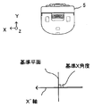
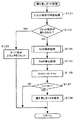
本実施形態では、捻り角度については、以下のようにして算出している。具体的には、まず、上述したように、構え直し操作時に、上記基準平面が算出される。このときに、当該基準平面に対する入力装置8のX軸の角度を算出して記憶する(以下、この角度を基準X角度と呼ぶ)。図26に、当該基準X角度の概念を示す模式図を示す。図26は、入力装置8が真下を向いている状況を想定して、Z軸の負方向から見た場合を示している。図26では、基準平面に対する入力装置8のX軸方向の角度は90°となっている。
In the present embodiment, the twist angle is calculated as follows. Specifically, first, as described above, the reference plane is calculated during the repositioning operation. At this time, the angle of the X axis of the
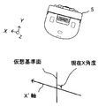
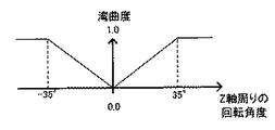
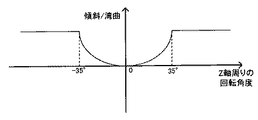
次に、スイング中(基準平面設定後の毎フレームの処理)、その時々の姿勢から、上記基準平面の算出手法と同じ手法を用いて、仮想的な基準平面を算出する(以下、仮想基準面と呼ぶ)。そして、当該仮想基準面に対する、入力装置8のX軸方向の角度を算出する。例えば、入力装置8の状態が、Z軸は真下に向いたまま、少し右に傾いたような状態と仮定し、Z軸と重力方向を含む平面である仮想基準面と、当該仮想基準面に対するこのときのX軸方向の角度が図27に示すような状態であるとする(以下、この角度を現在X角度と呼ぶ)。このときの現在X角度は、例えば100°であるとする。そして、上記の基準X角度と、当該現在X角度との角度差を算出し、この角度差を捻り角度として扱う。上記の例では、100°−90°=10°が捻り角度として扱われることになる。そして、このようにして算出された捻り角度に基づいて、パワーゲージ104の形状をスイング動作中(ショットするまでの間)にリアルタイムに湾曲させて表示する。例えば、パワーゲージ104の湾曲度を−1.0〜1.0の範囲内の値(負の値が左に湾曲することを示し、正の値が右に湾曲することを示す)で定義しておき、図28に示すように、捻り角度の値をこの範囲内の値に線形のグラフとなるように割り当てることで、パワーゲージ104の湾曲度を算出する。そして、当該湾曲度に基づいてパワーゲージ104の形状を湾曲させる。
Next, during the swing (processing for each frame after setting the reference plane), the virtual reference plane is calculated from the posture at that time using the same method as the reference plane calculation method (hereinafter referred to as the virtual reference plane). Called). And the angle of the X-axis direction of the
なお、捻り角度に関しては、Z軸の角速度だけを用いて捻り角度を算出することも考えられるが、実際の振り動作はZ軸まわりの回転だけでなくX軸まわりの回転やY軸まわりの回転の組み合わせによって行われる。そのため、例え「Z軸の角速度の積算値」がゼロであっても、手首の捻りがないとは言い切れないことが考えられる。そのため、本実施形態では、上記のように、入力装置8の姿勢に基づく平面を利用して算出する。
Regarding the twist angle, it is possible to calculate the twist angle using only the angular velocity of the Z axis, but the actual swinging motion is not only the rotation about the Z axis but also the rotation about the X axis and the rotation about the Y axis. It is done by a combination of Therefore, even if “the integrated value of the angular velocity of the Z axis” is zero, it can be said that there is no wrist twist. Therefore, in the present embodiment, calculation is performed using a plane based on the attitude of the
一方、振りかぶり量Hについては、基準姿勢を基準とした場合の、ゴルフクラブ102(入力装置8)を振りかぶっている角度、すなわち、入力装置8のZ軸がどのくらい地面から起き上がっているか、を計算する。そして、この振りかぶり角度を振りかぶり量Hに変換し、スイングバー106の位置に反映させる。これは、ゴルフスイングの場合、入力装置8のZ軸正方向が下を向いている状態が基本的な姿勢と考えられるため、この状態を基準としてZ軸の傾きを見ることで、振りかぶっている角度を把握することができる。
On the other hand, for the swing amount H, the angle at which the golf club 102 (input device 8) is swung with respect to the reference posture, that is, how much the Z axis of the
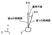
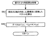
より具体的には、本実施形態では、以下のようにして振りかぶり量Hを算出する。まず、上記基準平面を基にして、図29に示すような、重力上方向をY方向、当該平面に対する垂直方向をX方向とする座標系{L}を設定する。以下、当該座標系を「{L}座標系」と呼ぶ。 More specifically, in the present embodiment, the swing-up amount H is calculated as follows. First, based on the reference plane, a coordinate system {L} is set, as shown in FIG. 29, in which the upward direction of gravity is the Y direction and the vertical direction to the plane is the X direction. Hereinafter, the coordinate system is referred to as “{L} coordinate system”.
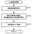
次に、スイング中の入力装置8のローカル座標系におけるZ軸正方向を上記{L}座標系に変換したベクトルDを算出する。
Next, a vector D obtained by converting the positive Z-axis direction in the local coordinate system of the
そして、当該ベクトルDの3軸成分(Dx、Dy、Dz)に基づき、以下の式を基づいて、振りかぶり角度θを算出する。
θ=Atan(Dx,−Dy+K×Dz)・・・式7
なお、変数K>0であるとする。また、上記式においては、水平にスイングされる場合(野球のようなスイング)を考慮して、Dzの要素を加味している。すなわち、DxおよびDyが共にゼロに近づいたとき(入力装置8が水平に構えられているような状態)のときに、角度の算出が不安定となることを防いでいる。また、Dzがプラス側にあれば、実際よりも入力装置8を下に向けているのと同じ効果があり、マイナス側では、実際よりも入力装置8を上に向けるのと同じ効果が得られる。つまり、水平に振っていても(野球のようなスイングをしていても)、縦に振っている場合(ゴルフスイング)とある程度同じような効果を得ることができる。
Then, based on the three-axis components (Dx, Dy, Dz) of the vector D, the swing angle θ is calculated based on the following equation.
θ = Atan (Dx, −Dy + K × Dz)
Note that variable K> 0. Further, in the above formula, the element of Dz is taken into consideration in consideration of a case where the swing is made horizontally (swing like a baseball). That is, the angle calculation is prevented from becoming unstable when both Dx and Dy are close to zero (a state where the
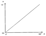
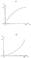
上記の式を用いた結果、構え直し操作が行われたときの姿勢(Bボタン32iが押されたときの姿勢)のときは、θ=0となる。また、前方(ゴルフボールを飛ばす方向)に入力装置8を振ると、θは正の値として算出される。また、入力装置8を振りかぶると、θは負の値として算出される。このように算出された振りかぶり角度θを振りかぶり量Hに変換する。例えば、振りかぶり角度θを−180°〜+180°の範囲とし、振りかぶり量Hは0.0〜1.0の範囲の値として、図30に示すような線形のグラフに基づいて振りかぶり角度θの絶対値を振りかぶり量Hに変換する。そして、当該振りかぶり量Hに応じてスイングバー106を上下させることで、振りかぶっている量を表示する。なお、本実施形態では、振りかぶり量Hが0.0のときは、スイングバー106はパワーゲージ104の一番下に来るものとし、振りかぶり量Hが1.0のときは、スイングバー106はパワーゲージ104の一番上に来るものとする。
As a result of using the above formula, θ = 0 when the posture is the posture when the repositioning operation is performed (the posture when the
このように、本実施形態では、上記のような捻り角度をパワーゲージ104の湾曲で示すと同時に、スイングバー106をパワーゲージ104内で上下させることで、例えば上記図18に示したような表示を行い、振りかぶり量(打球のパワーの目安)と手首の捻り具合(フェースの開き具合)という2つの要素をまとめて表示している。これにより、ショット時にゴルフボールに与える影響に関してプレイヤに直感的に把握させることが可能となる。
As described above, in the present embodiment, the twist angle as described above is indicated by the curvature of the
[構え直しガイド処理の概要]
次に、上記(3)構え直しガイドの表示処理の概要について説明する。上述のように、本実施形態では、上記図12で示したような、Bボタン32iの押下による「構え直し」操作を推奨する、構え直しガイド105を適切なタイミングで表示する。構え直しガイド105の表示タイミングについては、基本的には、Bボタン32iが押されたタイミングで内部的なカウンタ(以下、ガイド表示カウンタと呼ぶ)を用いてカウントアップを開始する。その後、毎フレーム、カウントアップされ、当該ガイド表示カウンタが所定値以上となれば、当該構え直しガイド105を表示するという処理を行っている。但し、本実施形態では、上記の「適切なタイミング」を決定するために、「構え直しの必要度」(以下、必要度Kr)と、「構え姿勢をとっている可能性」(以下、構え姿勢可能性Ks)を算出し、上記のカウントアップに反映する処理を行っている。更に、所定のタイミングでガイド表示カウンタのリセットも行うことで、「適切なタイミング」をより正確なものとしている。具体的には、以下のタイミングで上記ガイド表示カウンタをリセットしている。
(1)Bボタン32iが押されたとき。
(2)入力装置8の姿勢が、「構えなおし」のときに期待される姿勢(アドレスの姿勢)と大きく異なっているとき。例えば、入力装置8のZ軸正方向が水平より上を向いており、かつ、Y軸正方向が水平より下を向いているような場合(野球のバッターのような構え)。
(3)スイング中の状態の時。これは、角速度や加速度の絶対値が所定値以上か否かで判定する。具体的には、角速度については、その絶対値が30deg/secより大きいか否か、加速度については、その絶対値が0.2Gより大きいか否か。
[Overview of preparation guide processing]
Next, an outline of the display process of the (3) repositioning guide will be described. As described above, in this embodiment, the
(1) When the
(2) When the posture of the
(3) When in a swinging state. This is determined by whether or not the absolute values of angular velocity and acceleration are greater than or equal to predetermined values. Specifically, for the angular velocity, whether the absolute value is greater than 30 deg / sec, and for the acceleration, whether the absolute value is greater than 0.2G.
次に、上記必要度Kr、および、構え姿勢可能性Ksの算出方法等について説明する。まず、上記必要度Krとは、構え直しが必要であると考えられる度合いのことである。また、構え姿勢可能性Ksとは、プレイヤが構えの状態をとっている可能性である。ここでいう「構えの状態」とは、入力装置8の前面をある程度下側に向けているような状態(アドレスに近い状態)を想定するものである。つまり、ゴルフクラブを振りかぶっているような状態は除外される。
Next, a method for calculating the degree of necessity Kr and the attitude / posture possibility Ks will be described. First, the degree of necessity Kr is a degree at which repositioning is considered necessary. Further, the holding posture possibility Ks is a possibility that the player is in a holding state. Here, the “ready state” assumes a state in which the front surface of the
上記必要度Krの算出について、本実施形態では、以下のようにして算出している。まず、「今この瞬間にBボタンを押した」と仮定して仮の基準平面を作り、現在の基準平面との角度差の絶対値を算出する(当該2平面のなす角度とは、面法線と面法線のなす角度である)。そして、この角度差が0°であれば、構え直し不要と判定し、11°以上であれば、構え直しが必要と判定する。 In the present embodiment, the necessity degree Kr is calculated as follows. First, assuming that “the B button is pressed at this moment”, a temporary reference plane is created, and the absolute value of the angle difference from the current reference plane is calculated (the angle formed by the two planes is the surface method) The angle between the line and the surface normal). If this angle difference is 0 °, it is determined that repositioning is unnecessary, and if it is 11 ° or more, it is determined that repositioning is necessary.
ここで、必要度Krは0.0〜1.0の範囲の値をとるとし、0.0が構え直しの必要性がないことを示し、1.0が、構え直しの必要性が高いことを示す。すなわち、上記角度差が0°のときはKr=0.0、角度差が11°のときはKr=1.0とする。そして、0°〜11°の間のKrの値は、線形補間によって算出するものとする。 Here, the degree of necessity Kr takes a value in the range of 0.0 to 1.0, 0.0 indicates that there is no need for repositioning, and 1.0 indicates that the necessity for repositioning is high. Indicates. That is, Kr = 0.0 when the angle difference is 0 ° and Kr = 1.0 when the angle difference is 11 °. The value of Kr between 0 ° and 11 ° is calculated by linear interpolation.
次に、構え姿勢可能性Ksの算出については、角速度の安定状態Sw、加速度の安定状態Sa(つまり、激しい動きが発生していない状態)と、構え直し姿勢の正しさStという要素を用いて算出する。まず、角速度の安定状態Swについては、スイング中ではないと考えられるときの角速度、すなわち、角速度の絶対値が30deg/sec以下の場合に、当該角速度の絶対値を0.0〜1.0の値に換算してSwに割り当てる。加速度の安定状態Saについても同様に、スイング中の動きではないと考えられる加速度の絶対値0G〜0.2Gを、Sa0.0〜1.0の範囲に割り当てる。 Next, regarding the calculation of the posture attitude possibility Ks, the elements of the angular velocity stable state Sw, the acceleration stable state Sa (that is, a state where no intense movement has occurred), and the correctness of the posture to be repositioned St are used. calculate. First, regarding the stable state Sw of the angular velocity, when the angular velocity when it is considered that the swing is not being performed, that is, when the absolute value of the angular velocity is 30 deg / sec or less, the absolute value of the angular velocity is 0.0 to 1.0. Convert to a value and assign to Sw. Similarly, in the stable acceleration state Sa, an absolute value of acceleration 0G to 0.2G that is considered not to be a movement during a swing is assigned to a range of Sa 0.0 to 1.0.
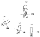
次に、構え直し姿勢の正しさStという要素は、入力装置8を下に下ろしている度合いを示す要素である。これは、入力装置8のX軸がどの程度水平状態に近いかによって示される。図31に、構え直し姿勢の正しさStの概念を示す。図31(a)に示すように、入力装置8の前面を下方に下げている状態であれば、入力装置8のローカル座標系におけるX軸は、水平状態(図31(d)参照)となる。この状態を、理想的な構え直し姿勢とすれば、その時々において算出される入力装置8の姿勢のX軸が水平か否かを見ることで(図31(b)、(c)参照)、構え直し姿勢の正しさStを算出することが可能となる。より具体的には、X軸の重力方向成分の絶対値を算出し、0.0〜1.0の範囲の値で示すことで、構え直し姿勢の正しさStとする。
Next, the element St of the correct posture St is an element indicating the degree to which the
そして、上記の要素を用いて、構え姿勢可能性Ksを以下の式で算出する。
Ks=Sw×Sa×St ・・・式8
Then, using the above-described elements, the posture attitude possibility Ks is calculated by the following equation.
Ks = Sw × Sa × St (8)
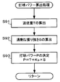
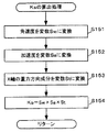
上記のようにして必要度Kr、および、構え姿勢可能性Ksが算出できれば、これに基づき、以下の式を用いてガイド表示カウンタCをカウントアップしていく。
C=C+Kr×Ks ・・・式9
そして、ガイド表示カウンタの値が30を越えれば、上記図12に示したような構え直しガイド105を表示する処理を実行する。これにより、「構え直し」が必要で効果的なタイミングを測って構え直しガイド105を表示することができ、プレイヤによる構え直し操作がより適切なタイミングで行われることが期待できる。
If the necessary degree Kr and the holding posture possibility Ks can be calculated as described above, the guide display counter C is counted up using the following formula based on this.
C = C + Kr ×
If the value of the guide display counter exceeds 30, the process for displaying the
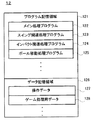
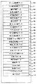
次に、ゲーム装置本体3によって実行されるゲーム処理の詳細を説明する。まず、ゲーム処理の際に外部メインメモリ12に記憶されるデータについて説明する。図32は、ゲーム装置3の外部メインメモリ12のメモリマップを示す図である。図32において、外部メインメモリ12は、プログラム記憶領域121およびデータ記憶領域126を含む。プログラム記憶領域121およびデータ記憶領域126のデータは、光ディスク4に記憶され、ゲームプログラム実行時には外部メインメモリ12に転送されて記憶される。
Next, details of the game process executed by the
プログラム記憶領域121は、CPU10によって実行されるゲームプログラムを記憶し、このゲームプログラムは、メイン処理プログラム122と、スイング関連処理プログラム123と、インパクト関連処理プログラム124などによって構成される。メイン処理プログラム122は、後述する図35のフローチャートの処理に対応するプログラムである。スイング関連処理プログラム123は、プレイヤが行うスイング動作に関する各種処理をCPU10に実行させるためのプログラムであり、インパクト関連処理プログラム124は、インパクトが発生したか否かを判定するための処理等をCPU10に実行させるためのプログラムである。また、ボール移動処理プログラム125は、打球を移動させるための処理をCPU10に実行させるためのプログラムである。
The
データ記憶領域126には、操作データ127やゲーム処理用データ128などのデータが記憶されるとともに、ゲーム処理中に一時的に用いられる各種フラグや変数も記憶される。
The
操作データ127は、コントローラ5からゲーム装置3へ送信されてくる操作データである。上述したように、コントローラ5からゲーム装置3へ1/200秒に1回の割合で操作データが送信されるので、外部メインメモリ12に記憶される操作データ127はこの割合で更新される。本実施形態においては、外部メインメモリ12には、最新の(最後に取得された)操作データのみが記憶されればよい。
The
操作データ127には、図33に示すように、角速度データ131、加速度データ132、マーカ座標データ133、および操作ボタンデータ134が含まれる。角速度データ131は、ジャイロセンサユニット7のジャイロセンサ55および56によって検出された角速度を示すデータである。ここでは、角速度データ131は、図3に示すXYZの3軸回りのそれぞれの角速度を示す。また、加速度データ132は、加速度センサ37によって検出された加速度(加速度ベクトル)を示すデータである。ここでは、加速度データ132は、図3に示すXYZの3軸の方向に関する加速度を各成分とする3次元の加速度ベクトルを示す。また、本実施形態においては、コントローラ5が静止している状態で加速度センサ37が検出する加速度ベクトルの大きさを"1"とする。つまり、加速度センサ37によって検出される重力加速度の大きさは"1"である。
As shown in FIG. 33, the
マーカ座標データ133は、撮像情報演算部35の画像処理回路41によって算出される座標、すなわち上記マーカ座標を示すデータである。マーカ座標は、撮像画像に対応する平面上の位置を表すための2次元座標系で表現される。なお、撮像素子40によって2つのマーカ6Rおよび6Lが撮像される場合には、2つのマーカ座標が算出される。一方、撮像素子40の撮像可能な範囲内にマーカ6Rおよび6Lのいずれか一方が位置しない場合には、撮像素子40によって1つのマーカのみが撮像され、1つのマーカ座標のみが算出される。また、撮像素子40の撮像可能な範囲内にマーカ6Rおよび6Lの両方が位置しない場合には、撮像素子40によってマーカが撮像されず、マーカ座標は算出されない。したがって、マーカ座標データ133は、2つのマーカ座標を示す場合もあるし、1つのマーカ座標を示す場合もあるし、マーカ座標がないことを示す場合もある。
The marker coordinate
操作ボタンデータ134は、各操作ボタン32a〜32iに対する入力状態を示すデータである。
The
ゲーム処理用データ128は、図34に示すように、入力装置姿勢データ141と、基準平面データ142と、基準X角度データ143と、仮想基準面データ144と、現在X角度データ145と、捻り角度データ146と、振りかぶり量データ147と、{L}座標系データ148と、ベクトルDのデータ149と、第1の候補面データ150と、第2の候補面データ151と、前回振りかぶり角度データ152と、前回追従角度データ153と、前回しなり角データ154と、ガイド表示カウンタ155と、打球パワーデータ156と、バックスピン率データ157と、打球パラメータ158と、現在状態データ159と、画像データ160と、ショットフラグ161と、飛球中フラグ162と、バックスピンフラグ163と、終了フラグ164等が記憶される。
As shown in FIG. 34, the
入力装置姿勢データ141は、入力装置8の姿勢を示すデータである。ここで、本実施形態では、入力装置8の姿勢を、互いに直交する3つのベクトルの組(すなわち、X軸、Y軸、Z軸)で表す。そして、本実施形態では、電源投入時、あるいは、ゲーム処理の開始時に、初期値として、ワールド座標系における入力装置8の姿勢(すなわち、入力装置8のローカル座標系でみた姿勢)をX軸=(1,0,0)、Y軸=(0,1,0)、Z軸=(0,0,1)と設定する。そして、ゲーム処理の開始後は、入力装置姿勢データ141で示される姿勢は、ジャイロセンサユニット7から取得した値に基づき、ワールド座標系に対する姿勢として算出されるものとする。
The input
基準平面データ142、基準X角度データ143は、上述したような基準平面、基準X角度を示すデータである。なお、本実施形態における各種平面を示すデータの保存形式については、各種平面が重力方向を含む(平行である)ため、平面を定めるという意味で、重力方向を軸とする回転の角度データを保存すればよい。また、冗長ではあるが、後述するような処理において利用しやすいという利点から、平面に含まれる水平ベクトル(重力方向と垂直なベクトル)1軸をデータとして保存するようにしても良い。更に、重力上方向のベクトル1軸と面の法線ベクトル1軸を加えて、3軸のベクトルデータとして保存しても良い。
The
仮想基準面データ144、現在X角度データ145は、上述したような捻り角度の算出等のために用いる仮想基準面、現在X角度を示すデータである。また、捻り角度データ146は、算出された上記捻り角度を示すデータである。
The virtual
振りかぶり量データ147は、上記振りかぶり量Hに対応するデータであり、{L}座標系データ148は、上記{L}座標系(上記図29参照)を示すデータである。また、ベクトルDのデータ149は、図29で示したベクトルDを示すデータである。
The swing-up
第1の候補面データ150および第2の候補面データ151は、基準平面を算出するために用いられる上記第1の候補面と第2の候補面を示すデータである。
The first
前回振りかぶり角度データ152、前回追従角度データ153、前回しなり角データ154は、インパクトの発生の判定等に用いられるデータであり、直前の処理ループにおいて算出された振りかぶり角度等の値を記憶したものである。
The previous
ガイド表示カウンタ155は、上記図12で示したような構え直しガイド105を表示するタイミングを測るためのカウンタである。
The
打球パワーデータ156は、打球のパワーを示すデータである(上記打球パワーPに対応するデータである)。バックスピン率データ157は、上記バックスピン率を示すデータである。また、打球パラメータ158は、打球を移動させるために用いる各種パラメータであり、打球が移動する軌道(弾道)や移動速度等のパラメータが含まれる。
The hit
現在状態データ159は、現在選択しているゴルフクラブの種類や、現在の場所に関するデータ(フェアウェイかラフか等)、風の向きや風の強さ等、仮想ゲーム空間内におけるプレイヤオブジェクトを取り巻く環境に関するデータが含まれる。
The
画像データ160は、ゲーム画像として表示される各種画像のデータである。上記構え直しガイド105の画像もこれに含まれる。
The
ショットフラグ161は、スイングの際にAボタン32dが押されているか否か、つまり、プレイヤが行うスイングが素振りか否かを判定するためのフラグであり、Aボタン32dが押されているときはオンに設定される。
The
飛球中フラグ162は、インパクトが発生する前(ボールが打たれる前)か、インパクトの発生後(ボールが打たれた後)かを判定するためのフラグである。当該フラグは、インパクト発生前はオフに設定され、インパクトが発生すれば、オンに設定される。
The flying
バックスピンフラグ163は、バックスピン率の算出処理を実行する必要があるか否かを示すフラグである。当該フラグは、インパクト発生と共にオンに設定され、その後、バックスピン率の算出が終わればオフに設定される(本実施形態では、インパクトの発生後、打球が着地するまでの間にバックスピン率の算出処理が実行されるため)。
The
終了フラグ164は、一打分に係る処理が終了したか否かを示すためのフラグである。
The
次に、図35〜図53を参照して、ゲーム装置3によって実行されるゲーム処理について説明する。ゲーム装置3の電源が投入されると、ゲーム装置3のCPU10は、ROM/RTC13に記憶されている起動プログラムを実行し、これによってメインメモリ33等の各ユニットが初期化される。そして、光ディスク4に記憶されたゲームプログラムが外部メインメモリ12に読み込まれ、CPU10によって当該ゲームプログラムの実行が開始される。なお、図35〜図37に示すフローチャートは、ゴルフにおける一打分の処理を示したものであり、プレイヤによる一打分の動作毎に、図35〜図37のフローチャートの処理が実行される。また、図35〜図37に示すステップS1〜ステップS21の処理ループは、1フレーム毎に繰り返し実行される。
Next, a game process executed by the
図35において、まず、CPU10は、初期化処理を実行する(ステップS1)。この処理では、各種フラグや変数の初期化が実行される。
In FIG. 35, first, the
次に、CPU10は、操作データ127を取得する(ステップS2)。続いて、CPU10は、飛球中フラグ162がオンか否かを判定する(ステップS3)。これは、インパクト前か後かを示すフラグである。当該判定の結果、移動中フラグがオンのとき、すなわち、インパクト後の状態であれば(ステップS3でYES)、ステップS4の処理に進む。このときの処理については後述する。
Next, the
一方、飛球中フラグ162がオフのときは(ステップS3でNO)、ボール103のインパクト前であるため、CPU10は、次に、環境設定処理を実行する(図36のステップS5)。この処理では、ショットに関連する環境の設定がなされる。例えば、プレイヤオブジェクト101の現在位置がフェアウェイかラフ、あるいはバンカーか等を判定し、打球パワーの上限を制限するような設定や、ボールの射出方向を地形等に応じて変更する処理が実行される。また、ここで設定された内容を示すデータは、現在状態データ159として外部メインメモリ12に記憶される。なお、当処理は、本発明の内容とは直接関連しないため、詳細な説明は省略する。
On the other hand, when the flying
次に、CPU10は、上記ステップS2で取得した操作データ127で示される操作内容が、スイング操作以外の操作にかかる内容であるか否かを判定する(ステップS6)。スイング操作以外の操作とは、例えば、ゴルフクラブを選択するための操作や、ショットする方向を変化させる(仮想カメラの向きを変える)ための操作等、本発明の内容に関わること以外の操作である。なお、ゴルフクラブの選択操作が行われたときは、選択したゴルフクラブの種類(ドライバやアイアン等)を示すデータは現在状態データ159の一部として外部メインメモリ12に記憶される。
Next, the
当該判定の結果、スイング操作以外の操作が行われていたときは(ステップS6でYES)、CPU10は、後述するステップS19の処理に進む。一方、スイング操作以外の操作ではないときは(ステップS6でNO)、次に、CPU10は、操作データ127で示される操作内容がBボタン32iの押下であるか否かを判定する(ステップS7)。当該判定の結果、Bボタン32iが押されていたときは(ステップS7でYES)、CPU10は、構え直し処理を実行する(ステップS8)。当該構え直し処理においては、上述したような基準平面を算出する処理等が実行される。
As a result of the determination, when an operation other than the swing operation has been performed (YES in step S6), the
図38は、上記ステップS8で示した構え直し処理の詳細を示すフローチャートである。図38において、まず、CPU10は、上記操作データ127に含まれる加速度データ132および角速度データ131に基づいて入力装置8の姿勢を算出する処理を実行する(ステップS31)。本処理は、どのような処理方法であっても良いが、本実施形態では、上記のように、まず、ジャイロセンサユニット7で検出された角速度に基づいて入力装置8の姿勢を算出する。角速度から姿勢を算出する方法は、例えば、初期姿勢に(単位時間あたりの)角速度を逐次加算する方法がある。すなわち、ジャイロセンサユニット7から逐次出力される角速度に基づいて、初期状態から開始して、前回算出された姿勢に逐次変化を加えて更新していくことによって、現在の姿勢を算出することができる。次に、加速度センサ37で検出された加速度データに基づいて上記角速度から算出された姿勢を補正する。本実施形態では、上記角速度から算出された姿勢を加速度データから決まる姿勢へと近づける補正を行う。次に角速度による姿勢の更新を行うときには、当該補正された姿勢にたいして角速度を加えることになる。加速度データから決まる姿勢とは、具体的には、加速度データが示す加速度の向きが鉛直下向きであると想定する場合における入力装置8の姿勢を指す。すなわち、加速度データが示す加速度が重力加速度であると仮定して算出された姿勢である。加速度によって決められる姿勢は、センサが静止しているときには正確だが、動いているときには誤差があるという性質がある。一方、ジャイロセンサは、センサ出力に誤差が含まれる場合に、算出された姿勢には時間と共に誤差が蓄積していくという性質がある。したがって、常に補正を加えながら姿勢を更新していくことによって、誤差の少ない姿勢が算出される。このようにして補正された姿勢が、入力装置姿勢データ141として外部メインメモリ12に記憶される。以下(この姿勢のことを、現在姿勢と呼ぶ)。なお、加速度データを反映させない場合は、角速度の積分結果を初期姿勢に反映させた姿勢としてもよい。
FIG. 38 is a flowchart showing details of the readjustment process shown in step S8. In FIG. 38, first, the
次に、CPU10は、基準平面設定処理を実行する(ステップS32)。図39は、当該基準平面設定処理の詳細を示すフローチャートである。図39において、まず、CPU10は、現在の入力装置8のローカル座標系でのZ軸(以下、ローカルZ軸と呼ぶ)方向と、重力方向とを含む平面を第1の候補面として算出し、第1の候補面データ150として外部メインメモリ12に記憶する(ステップS41)。
Next, the
次に、CPU10は、現在姿勢におけるローカルZ軸を重力方向に向けるような回転行列を算出する。そして、現在の入力装置8のローカル座標系におけるY軸(以下、ローカルY軸と呼ぶ)に対して、上記算出した回転行列を適用することで、Y'軸を算出する(ステップS42)。
Next, the
次に、CPU10は、当該Y'軸と重力方向とを含む平面を第2の候補面として算出し、第2の候補面データ151として外部メインメモリ12に記憶する(ステップS43)。
Next, the
次に、現在の基準平面(直近に算出された基準平面)と、上記第1の候補面、第2の候補面と現在の判定面とのなす角(上記図23のθA、θB)をそれぞれ算出する(ステップS44)。次に、上記の角度に基づき、上述した式1(式2や式3でもよい)を用いて、新たな基準平面を算出し、基準平面データ142として外部メインメモリ12に記憶する(ステップS45)。
Next, the angles (θA, θB in FIG. 23) formed by the current reference plane (the reference plane calculated most recently) and the first candidate plane, the second candidate plane, and the current determination plane are respectively set. Calculate (step S44). Next, based on the above angle, a new reference plane is calculated using the above-described formula 1 (may be
ここで、ゲーム処理の開始後、当該処理が初めて実行されるときは、まだ基準平面が算出されていない状態である。そのため、初回実行時のみ、基準平面を以下のようにして算出する。すなわち、CPU10は、上記第1の候補面と第2の候補面とがなす角(θA+θB)を2分割するような平面を算出し(つまり、2つの角の平均をとる)、この平面を新たな基準平面とする。
Here, when the process is executed for the first time after the start of the game process, the reference plane has not yet been calculated. Therefore, the reference plane is calculated as follows only at the first execution. That is, the
なお、初回実行時における基準平面の算出にすいては、上記のような方法の他、次のような方法を用いて算出しても良い。すなわち、Z軸方向と重力方向との角度差を第1の候補面の重みとし上記Y'軸方向と重力方向との角度差を、第2の候補面の重みとする。そして、第1の候補面と第2の候補面の加重平均をとることで、新たな基準平面としてもよい。 In addition, as for the calculation of the reference plane at the first execution, the following method may be used in addition to the above method. That is, the angle difference between the Z-axis direction and the gravity direction is set as the weight of the first candidate plane, and the angle difference between the Y′-axis direction and the gravity direction is set as the weight of the second candidate plane. And it is good also as a new reference plane by taking the weighted average of a 1st candidate surface and a 2nd candidate surface.
次に、CPU10は、(新たな)基準平面に基づいて、上述したような{L}座標系(上記図29参照)を設定する(ステップS46)。
Next, the
次に、CPU10は、上記ローカルZ軸が基準平面に平行になるような仮想的な回転を、現在の入力装置8のX軸(以下、ローカルX軸と呼ぶ)に適用することで、X'軸を算出する(ステップS47)。図40は、当該処理の概要を示す図である。図40(a)は、実際の入力装置8の姿勢を示し、図40(b)は、上記のような回転を加えたことによる、入力装置8の仮想的な姿勢の状態を示している。
Next, the
次に、CPU10は、上記基準平面に対する上記X'軸の角度を算出し、基準X角度データ143として外部メインメモリ12に記憶する(ステップS48)。以上で、基準平面設定処理は終了する。
Next, the
図37に戻り、基準平面設定処理が終了すれば、次に、CPU10は、プレイヤオブジェクト101の姿勢制御等を行う(ステップS33)。すなわち、CPU10は、上記算出した現在姿勢に基づいてゴルフクラブ102等の位置を移動したり、プレイヤオブジェクト101に、構え直しを行っている様子を取らせる(例えば、ゴルフクラブを握り直すようなそぶりを行わせる)処理を実行したりする。
Returning to FIG. 37, when the reference plane setting process is completed, the
次に、CPU10は、構え直しガイド105の表示(上記図12参照)のために用いるガイド表示カウンタ155をリセットする(ステップS34)。
Next, the
次に、CPU10は、パワーゲージ104の表示内容を初期化する(ステップS35)。具体的には、パワーゲージ104の形状を、上記図8や図12で示したように真っ直ぐな状態とし、スイングバー106の位置をパワーゲージ104の一番下に設定する。以上で、構え直し処理は終了する。
Next, the
図36に戻り、構え直し処理が終了すれば、次に、CPU10は、描画処理を行う(ステップS20)。すなわち、仮想カメラで仮想ゲーム空間を撮影した画像をゲーム画像としてテレビ2に表示する処理が実行される。ステップS20の後、CPU10は、終了フラグ164がオンか否かでゲーム終了か否かを判断し(ステップS21)、YESの場合、ゲーム処理を終了し、NOの場合、ステップS2に戻って、ゲーム処理を繰り返す。
Returning to FIG. 36, when the repositioning process is completed, the
次に、上記ステップS7で、Bボタン32iが押されていないと判定されたときの処理(ステップS7でNO)について説明する。このときは、次に、CPU10は、操作データ127の操作内容がAボタンの押下であるか否か、つまり、Aボタン32dが押されているか否かを判定する(ステップS9)。
Next, a process when it is determined in step S7 that the
当該判定の結果、Aボタン32dが押されているときは(ステップS9でYES)、プレイヤが行うスイングが、「素振り」ではなく、ボールを打ちに行く「ショット」動作として扱うための設定処理が行われる。まず、CPU10は、ショットフラグ161がオンか否かを判定する(ステップS13)。その結果、ショットフラグ161がオンでないときは(ステップS13でNO)、Aボタン32dが押された直後の状態と考えられるため、CPU10は、ショットフラグ161をオンに設定する(ステップS14)。次に、プレイヤオブジェクト101をボール103の位置に向けて前進させる(近づける)ような制御(上記図8から図10の状態にするような制御)を実行する(ステップS15)。その後、CPU10は後述するステップS16の処理に進む。
As a result of the determination, when the
一方、ステップS13の判定の結果、ショットフラグ161がオンに設定されていれば(ステップS13でYES)。Aボタン32dが押され続けている状態と考えられるため、CPU10は後述のステップS16の処理に進む。
On the other hand, if the result of determination in step S13 is that the
一方、上記ステップS9の判定の結果、Aボタン32dが押されていないときは(ステップS9でNO)、プレイヤが行うスイングを「素振り」として扱うための設定処理を行うことになる。まず、CPU10は、ショットフラグ161がオンか否かを判定する(ステップS10)。その結果、ショットフラグ161がオンであれば(ステップS10でYES)、Aボタン32dを押し続けていた状態からAボタン32dを離した直後の状態と考えられるため、CPU10は、ショットフラグ161をオフに設定する(ステップS11)。次に、CPU10は、プレイヤオブジェクト101をボール103の位置から後退させるような制御(上記図10から図8の状態に戻す)を行う(ステップS12)。その後、CPU10は、後述のステップS16の処理に進む。
On the other hand, if the result of the determination in step S9 is that the
一方、ステップS10の判定でショットフラグ161がオフと判定されたときは(ステップS10でNO)、CPU10は、上記ステップS11〜S12の処理は実行せずに、後述のステップS16の処理に進む。
On the other hand, when it is determined in step S10 that the
次に、CPU10は、スイング関連処理を実行する(図37のステップS16)。図41は、当該スイング関連処理の詳細を示すフローチャートである。図41において、まず、CPU10は、操作データ127に基づいて、入力装置の現在姿勢を算出する(ステップS51)。
Next, the
次に、CPU10は、パワーゲージ更新処理を実行する(ステップS52)。この処理は、上述したようなパワーゲージ104の表示内容を決定(更新)するための処理である(処理概要の説明で上述した(2)パワーゲージ関連処理に相当)。
Next, CPU10 performs a power gauge update process (step S52). This process is a process for determining (updating) the display content of the
図42は、当該パワーゲージ更新処理の詳細を示すフローチャートである。図42において、まず、CPU10は、捻り角度算出処理を実行する(ステップS61)。この処理は、上述したような捻り角度を求めるための処理である。図43は、当該捻り角度算出処理の詳細を示すフローチャートである。図43において、まず、CPU10は、現在の入力装置の姿勢に基づいて、仮想的に基準平面を生成する(ステップS71)。つまり、仮に今Bボタン32iが押されたものと仮想して、上述したような基準平面を生成する。以下、当該仮想的な基準平面を、仮想基準面と呼ぶ。仮想基準面生成のための処理としては、図39を用いて説明したステップS41〜S45の処理と同じ処理が実行され、生成された平面が仮想基準面データ144として外部メインメモリ12に記憶される。
FIG. 42 is a flowchart showing details of the power gauge update process. In FIG. 42, first, the
次に、CPU10は、入力装置8のローカルZ軸を当該仮想基準面に対して平行にするような回転を、ローカルX軸に適用し、仮想X'軸を算出する(ステップS72)。次に、仮想基準面に対する仮想X'軸の角度を算出し、現在X角度データ145として外部メインメモリ12に記憶する(ステップS73)。当該ステップS72およびS73の処理は、仮想基準面を対象とする点を除けば、図39を用いて上述したステップS47およびS48の処理と同様となるため、詳細な説明は省略する。
Next, the
次に、CPU10は、以下の式で捻り角度を算出し、捻り角度データ146として記憶する(ステップS74)。
捻り角度=現在X角度−基準X角度 ・・・式10
以上で、捻り角度算出処理は終了する。
Next, the
Twist angle = current X angle−reference X angle
Thus, the twist angle calculation process ends.
図42に戻り、捻り角度算出処理の次に、CPU10は、振りかぶり角度算出処理を実行する(ステップS62)。図44は、当該振りかぶり角度算出処理の詳細を示すフローチャートである。図44において、まず、CPU10は、上記(スイング角度算出の図A)を用いて示したように、現在姿勢におけるローカルZ軸を、上述したような{L}座標系に変換することで、ベクトルDを算出する(ステップS81)。
Returning to FIG. 42, after the twist angle calculation process, the
次に、CPU10は、上述した式7(θ=Atan(Dx,−Dy+K×Dz))を用いて、振りかぶり角度θを算出する(ステップS82)。なお、振りかぶり角度θは、上述したように、構え直し操作を行ったときの姿勢で0、前方に振ると正の値、振りかぶると負の値が算出される。以上で、振りかぶり角度算出処理は終了する。
Next, the
図42に戻り、振りかぶり角度θが算出できれば、次に、CPU10は、当該振りかぶり角度θの絶対値に基づいて、捻り角度をパワーゲージ104の湾曲に反映させる度合い(反映度)を決定するための処理を実行する(ステップS63)。この処理は、振りかぶり角度が大きいときほど(大きく振りかぶっているときほど)、捻り角度の影響を小さくし、振りかぶり角度が小さいほど(ゴルフクラブ102のヘッドがボール103に近いほど)、捻り角度の影響を大きくするための処理である。つまり、仮に手首の捻り角度が同じとして、大きく振りかぶっているときは、パワーゲージ104はあまり湾曲しないが、ボール103に近づくほど、捻り角度がパワーゲージ104の湾曲に反映される度合いが高くなり、より湾曲して表示されるような処理を実行する。例えば、反映度を0.0(反映度弱)〜1.0(反映度強)とすると、振りかぶり角度が0度のときを反映度1.0とし、振りかぶり角度の絶対値が180°を反映度0.0として、この間の値が線形のグラフとなるように割り当てるようにする(もちろん、非線形で割り当てるようにしても良い)。
Returning to FIG. 42, if the swing-up angle θ can be calculated, the
次に、CPU10は、上記捻り角度と反映度に基づいて、パワーゲージ104の形状を湾曲させる(ステップS64)。例えば、CPU10は、上記図28で示したようなグラフに相当する関数を用いて、捻り角度−35°〜+35°を、湾曲度−1.0〜1.0の範囲の値に変換する処理を実行する。そして、この変換の際に、上記反映度を係数として用いる。例えば、捻り角度を10°とすると、反映度1.0(アドレスに近い状態)であれば、10°がそのまま湾曲度に反映されるが、反映度が0.5(半分くらいまで振りかぶっている状態)であれば、当該0.5を乗じた値を湾曲度として算出する。
Next, the
続いて、CPU10は、振りかぶり角度θを振りかぶり量Hに換算する(ステップS65)。具体的には、CPU10は、上記図30で示したようなグラフに相当する関数を用いて、振りかぶり角度θ(−180°〜+180°)の絶対値を振りかぶり量H(0.0〜1.0)に変換する。
Subsequently, the
次に、CPU10は、上記振りかぶり量Hに基づいて、スイングバー106を移動させる(ステップS66)。以上で、パワーゲージ更新処理は終了する。
Next, the
図41に戻り、パワーゲージ更新処理の次に、CPU10は、打球パワー算出処理を実行する(ステップS53)。図45は、当該打球パワー算出処理の詳細を示すフローチャートである。図45において、まず、CPU10は、上記の「振り下ろし動作反映処理の概要」において説明したような、追従係数Ktの設定、および、これを用いた追従量Tの算出を実行する(ステップS91)。
Returning to FIG. 41, after the power gauge update process, the
次に、CPU10は、上述した過剰な振り強さSを算出する(ステップS92)。すなわち、加速度を8割減と仮定して、上記追従量Tと同様の計算を行うことで過剰な振り強さSを算出する。
Next, the
次に、CPU10は、上述したような式4を用いて打球パワーPを算出し、打球パワーデータ156として外部メインメモリ12に記憶する(ステップS93)。以上で、打球パワー算出処理は終了する。
Next, the
図41に戻り、打球パワー算出処理が終われば、次に、CPU10は、しなり角算出処理を実行する(ステップS54)。この処理は、上述したようなバックスピン率を算出するために用いる、ゴルフクラブ102のヘッド部分のしなりを算出するための処理である。図46は、当該しなり角算出処理の詳細を示すフローチャートである。図46において、まず、CPU10は、しなり特性の設定を行う(ステップS101)。すなわち、CPU10は、上記変数Kp(ばね)およびKd(ダンパー)を、振りかぶり角度θの絶対値に応じて設定する。具体的には、振りかぶり角度の絶対値|θ|である0°〜180°のうち、0°〜90°の範囲の値に対して、Kpについては、0.01〜0.015の値を割り当てる(90°以上については、Kpは一律に0.015とする)。また、Kdについては、同じく0°〜90°に対して、0.001〜0.3の値を割り当てる(90°以上については、Kdは一律に0.3とする)。これにより、インパクト付近ではしなりやすく、遠いときはしなりにくいという、しなりについての特性をもたせることができる。
Returning to FIG. 41, when the hitting ball power calculation process is completed, the
次に、CPU10は、上記式6を用いてクラブヘッド部分の加速度Aを算出し、更に、上述したような追従角度θh(上記図25参照)を算出する(ステップS102)。
Next, the
次に、CPU10は、上記式5(φ=θh−θ)を用いて、しなり角φを算出する(ステップS103)。以上で、しなり角算出処理は終了する。
Next, the
図41に戻り、しなり角算出処理が終了すれば、次に、CPU10は、入力装置8の現在姿勢に基づいてプレイヤオブジェクト101やゴルフクラブ102等の姿勢を更新する(ステップS55)。以上で、スイング関連処理は終了する。
Returning to FIG. 41, when the bending angle calculation process is completed, the
図37に戻り、スイング関連処理が終われば、次に、CPU10は、インパクト関連処理を実行する(ステップS17)。本処理では、インパクトが発生したか否かの判定や、インパクトが発生したときの打球に関するパラメータを決めるための処理が実行される。
Returning to FIG. 37, if the swing related process is completed, the
図47は、当該インパクト関連処理の詳細を示すフローチャートである。図47において、まず、CPU10は、ゴルフクラブ102が上記基準平面を通過したか否かを判定する(ステップS111)。より具体的には、CPU10は、前回振りかぶり角度データ152を参照し、直前のフレーム(直前の処理ループ)で算出された振りかぶり角度θの値を取得する。そして、当該値と、現在のフレームでの処理で算出された振りかぶり角度θとを比較して、当該振りかぶり角度θの値がマイナス値からプラス値に変化したか否かを判定することで、基準平面を通過したか否かを判定する。なお、この判定は、主にバックスピン動作を行っていない、通常のスイングが行われた場合を想定した判定である。
FIG. 47 is a flowchart showing details of the impact-related processing. In FIG. 47, first, the
当該判定の結果、ゴルフクラブ102が基準平面を通過したと判定されたときは(ステップS111でYES)、CPU10は、後述のステップS113の処理に進む。一方、ステップS111の判定の結果、ゴルフクラブ102が基準平面を通過していないと判定されたときは(ステップS111でNO)、CPU10は、バックスピン動作が行われたときのゴルフクラブ102のヘッド部のしなりを考慮して、基準平面を通過したか否かの判定を行う(ステップS112)。つまり、上述したようなバックスピン動作が行われたとき、プレイヤはボールをインパクトしたつもりであっても、上記振りかぶり角度θで判定した場合、仮想ゲーム空間内においては、ぎりぎりでゴルフクラブ102がボール103に当たっておらず(基準平面を通過していない)、直前で止められた結果になっているという場合がある。このような場合を想定して、バックスピン動作を行ったときに発生すると考えられる、ゴルフクラブ102のヘッド部の前方へのしなりを考慮して、前方にしなったヘッド部分が基準平面を通過したか否か、すなわち、ボール103にインパクトしたか否かを判定するものである。そのため、CPU10は、上記追従角度θhの値がマイナス値からプラス値に変化したか否かを判定することで、基準平面を通過したか否かを判定する。そして、基準平面を通過していれば(ステップS112でYES)、ステップS113の処理に進み、基準平面を通過していないときは(ステップS112でNO)、CPU10は、インパクト関連処理を終了する。
As a result of the determination, when it is determined that the
次に、CPU10は、ショットフラグ161がオンか否かを判定する(ステップS113)。つまり、今回行われたスイングが、「素振り」か否かを判定している。その結果、ショットフラグ161がオフのときは(ステップS113でNO)、「素振り」が行われているため、CPU10は、打球パワーデータ156を読み出し、打球パワーPをパワーバー107(図16等参照)に変換して表示する(ステップS114)。このとき、パワーゲージ104の形状が湾曲していれば、その湾曲に沿ってパワーバー107も湾曲した形状として表示する。
Next, the
一方、上記ステップS113の判定の結果、ショットフラグ161がオンのときは(ステップS113でYES)、CPU10は、打球を飛ばすためのショット処理を実行する(ステップS115)。図48は、上記ショット処理の詳細を示すフローチャートである。図48において、まず、CPU10は、バックスピンフラグ163にオンを設定する(ステップS121)。更に、CPU10は、飛球中フラグ162をオンに設定する(ステップS122)。
On the other hand, if the result of the determination in step S113 is that the
次に、CPU10は、打球パワーデータ156を読み出し、上記打球パワーPをパワーバー107に変換して表示する(ステップS123)。続いて、CPU10は、上記打球パワーPや捻り角度、更には、(現在状態データ159を参照して得られる、現在選択されているゴルフクラブの種類や打った場所(フェアウェイやラフ等)、風向き等のデータに基づいて、打球の弾道や移動速度等の打球のパラメータを算出する(ステップS124)。算出されたパラメータは、打球パラメータ158として外部メインメモリ12に記憶される。以上で、ショット処理は終了する。
Next, the
図41に戻り、ショット処理が終了すれば、次に、CPU10は、上記振りかぶり角度θを前回振りかぶり角度データ152として外部メインメモリ12に記憶する(ステップS116)。更に、CPU10は、上記追従角度θhを前回追従角度データ153として外部メインメモリ12に記憶する(ステップS117)。また、CPU10は、上記スイング関連処理において算出されたしなり角を前回しなり角データ154として外部メインメモリ12に記憶する(ステップS118)。以上で、インパクト関連処理は終了する。
Returning to FIG. 41, when the shot processing is completed, the
図37に戻り、インパクト関連処理が終了すれば、次に、CPU10は、構え直しガイド処理を実行する(ステップS18)。本処理は、上記図12に示したような構え直しガイド105の表示タイミングを測り、当該ガイドメッセージを表示するための処理である(上述した処理概要の説明における(3)ガイドメッセージ表示関連処理に相当)。
Returning to FIG. 37, if the impact-related processing is completed, the
図49は、上記ステップS18で示した構え直しガイド処理の詳細を示すフローチャートである。図49において、まず、CPU10は、ガイド表示カウンタ155をリセットする条件が満たされているか否かの判定を行う(ステップS131)。すなわち、上述したような、入力装置8の姿勢が、「構えなおし」のときに期待される姿勢(アドレスに近い姿勢)と大きく異なっているか否かという条件と、スイング中の状態か否かという条件である。(なお、Bボタンが押されたか否かという条件については、上記図38のステップS34の処理で対応している)。
より具体的には、
(1)入力装置のローカルZ軸が水平よりも上を向いていて、ローカルY軸が水平より下を向いているか(例えば、野球のバットを持ったときの構えなど)。
(2)角速度の絶対値が30deg/secより大きいか
(3)加速度の絶対値が0.2Gより大きいか。
という3つの条件について、それぞれ満たされているか否かを判定する。
FIG. 49 is a flowchart showing details of the readjustment guide process shown in step S18. In FIG. 49, first, the
More specifically,
(1) Whether the local Z-axis of the input device is above the horizontal and the local Y-axis is below the horizontal (for example, when holding a baseball bat).
(2) Whether the absolute value of angular velocity is greater than 30 deg / sec. (3) Whether the absolute value of acceleration is greater than 0.2G.
It is determined whether each of the three conditions is satisfied.
次に、CPU10は、上記3つの条件のうち、一つでも条件が満たされているか否かを判定する(ステップS132)。その結果、1つでも条件が満たされていれば(ステップS132でYES)、リセット条件が満たされたとして、CPU10は、ガイド表示カウンタ155をリセットし(ステップS133)、構え直しガイド処理を終了する。
Next, the
一方、上記3つの条件のいずれも満たされていないときは(ステップS132でNO)、CPU10は、ガイド表示カウンタをカウントアップするための処理を実行する。具体的には、まず、CPU10は、上述したような、(構え直しの)必要度Krの算出処理を実行する(ステップS134)。図50は、必要度Krの算出処理の詳細を示すフローチャートである。図50において、まず、CPU10は、上述したような仮想基準面を算出し、外部メインメモリ12に記憶する(ステップS141)。この処理は、図42を用いて上述したステップS71の処理と同様の処理である。
On the other hand, when none of the above three conditions is satisfied (NO in step S132), the
次に、CPU10は、現在の基準平面と上記仮想基準面との角度差(面法線と面法線のなす角度)の絶対値を算出する(ステップS142)。
Next, the
次に、CPU10は、上記ステップS142で算出した角度差を必要度Krに変換する(ステップS143)。具体的には、角度差が11°以上のときは構え直し不要、角度差が0°であれば、構え直し不要と定義し、この間の0°〜11°までの角度差を、線形補間を用いて0.0〜1.0の範囲内の値に変換して、必要度Krとする。以上で、必要度Krの算出処理は終了する。
Next, the
図49に戻り、次に、CPU10は、構え姿勢可能性Ksの算出処理を実行する(ステップS135)。図51は、上記ステップS135で示した構え姿勢可能性Ksの算出処理の詳細を示すフローチャートである。図51において、まず、操作データ127に含まれる角速度データに基づき、現在の角速度を角速度の安定状態を示す変数Swに変換する(ステップS151)。具体的には、角速度の絶対値0deg/sec〜30deg/secを、線形補間を用いて0.0〜1.0の範囲内の値に変換し、変数Swとする。
Returning to FIG. 49, next, the
次に、CPU10は、操作データ127に含まれる加速度データに基づき、現在の加速度を加速度の安定状態を示す変数Saに変換する(ステップS152)。具体的には、加速度の絶対値0G〜0.2Gを、線形補間を用いて0.0〜1.0の範囲内の値に変換し、変数Saとする。
Next, the
次に、CPU10は、ローカルX軸の重力方向成分を、構え直し姿勢の正しさを示す変数Stに変換する(ステップS153)。すなわち、図31を用いて上述したような、X軸の水平度合いを0.0(X軸が垂直な状態)〜1.0(X軸が水平な状態)の範囲の値に換算して変数Stとする。
Next, the
次に、CPU10は、上述した式8(Ks=Sw×Sa×St)を用いて、構え姿勢可能性Ksを算出する(ステップS154)。以上で、構え姿勢可能性Ksの算出処理は終了する。
Next, the
図49に戻り、次に、CPU10は、必要度Krおよび構え姿勢可能性Kに基づき、上記の式9(C=C+Kr×Ks)を用いてかまえ表示カウンタCをカウントアップする(ステップS136)。
Returning to FIG. 49, next, the
次に、CPU10は、構え表示カウンタCが30を越えたか否かを判定する(ステップS137)。その結果、30を越えていれば(ステップS137でYES)、上記図10で示したような構え直しガイド105を表示するための処理を実行する(ステップS138)。一方、30を越えていないときは(ステップS137でNO)、CPU10は、そのまま構え直しガイド処理を終了する。
Next, the
図37に戻り、構え直しガイド処理が終了すれば、次に、CPU10は、その他のゲーム処理を実行する(ステップS19)。すなわち、本発明に関すること以外のゴルフゲームにかかる処理を実行する。その後、上述したステップS20以降の処理が実行される。
Returning to FIG. 37, when the repositioning guide process is completed, the
次に、上記図35のステップS3の判定の結果、飛球中フラグ162がオンのときの処理(ステップS3でYES)を説明する。このときは、インパクトが発生した後、つまり、ショットした後ということになるため、CPU10は、ボール移動処理を実行する(ステップS4)。この処理では、打球を移動させるための処理、および、バックスピンに関する処理が実行される。
Next, the processing when the flying
図52は、上記ボール移動処理の詳細を示すフローチャートである。図52において、まず、CPU10は、バックスピンフラグがオンか否かを判定する(ステップS161)。その結果、オンのときは(ステップS161でYES)、CPUはバックスピン率設定処理(ステップS162)を実行してからステップS163の処理に進み、オフのときは(ステップS161でNO)、ステップS162の処理は実行せずにステップS163の処理に進む。
FIG. 52 is a flowchart showing details of the ball movement process. In FIG. 52, first, the
図53は、上記ステップS162で示したバックスピン率設定処理の詳細を示すフローチャートである。この処理では、クラブヘッド部分の前方へのしなり角の最大値を検出してバックスピン率に反映するための処理が実行される。図53において、まず、CPU10は、上記しなり角φを算出するためのしなり角算出処理を実行する(ステップS171)。本処理は、図40を用いて説明したステップS54の処理と同じであるため、説明は省略する。
FIG. 53 is a flowchart showing details of the backspin rate setting process shown in step S162. In this process, a process for detecting the maximum value of the forward bending angle of the club head portion and reflecting it in the backspin rate is executed. In FIG. 53, first, the
次に、CPU10は、算出されたしなり角φの値が、正の値であるか否かを判定する(ステップS172)。当該判定の結果、正の値でないときは(ステップS172でNO)、CPU10は、算出されたしなり角で前回しなり角データ154を更新し(ステップS177)、バックスピン率設定処理を終了する。
Next, the
一方、算出されたしなり角φの値が、正の値のときは(ステップS172でYES)、次に、CPU10は、しなりの折り返しが発生したか否かを判定する(ステップS173)。しなりの折り返しとは、バックスピンをかけるようなスイングによってゴルフクラブのヘッド部分が前方へしなった後、反発してまた後方へ戻り始めたときのことである。例えば、CPU10は、前回しなり角データ154で示されるしなり角が上記ステップS171で算出されたしなり角φより大きければ、折り返しが発生したと判定する。そして、当該判定の結果、折り返しが発生していないときは(ステップS173でNO)、まだ前方へ向かってのしなりが継続している状態と考えられるため、CPU10は、上記ステップS177の処理を実行してから、バックスピン率設定処理を終了する。
On the other hand, when the calculated value of the bending angle φ is a positive value (YES in step S172), the
一方、折り返しが発生したときは(ステップS173でYES)、次に、CPU10は、そのときに選択されているゴルフクラブの種類等に基づいて、しなり角のバックスピンへの反映率を決定する処理を実行する(ステップS174)。例えば、クラブの種類がドライバであれば、バックスピンがかかりにくくなるよう、反映率としては低い値を設定する。
On the other hand, when the turn-back has occurred (YES in step S173), the
次に、CPU10は、上記決定された反映率と、前回しなり角データ154で示されるしなり角(すなわち、前方へのしなりの最大値となる)に基づき、バックスピン率を決定する(ステップS175)。決定されたバックスピン率は、バックスピン率データ157として外部メインメモリ12に記憶される。
Next, the
次に、CPU10は、バックスピンフラグ163をオフに設定する(ステップS176)。以上で、バックスピン率設定処理は終了する。
Next, the
図52に戻り、バックスピン率設定処理の後、CPU10は、打球パラメータ158に基づいて、打球(ボール103)を移動する。また、バックスピン率が決定した後は、当該バックスピン率にも基づいて打球を移動させる(ステップS163)。つまり、ショットの直後は、まだバックスピン率は未決定の状態であるため、打球パラメータ158のみに基づいて(バックスピンがかかっていない状態で)打球が移動される。その後、バックスピン率が決定した後(バックスピンフラグ163がオフになった後)は、打球パラメータ158に加えてバックスピン率データ157も用いて打球を移動させる。一般的に、バックスピンのかかった打球は、高く上がるような弾道となる。そのため、上記のように途中からバックスピン率を適用して打球を移動させることで、打球が途中から急上昇するような弾道になり得る。また、このとき、例えば、打球を追いかけるようなカメラワークを行うための仮想カメラの設定等も適宜行われる。
Returning to FIG. 52, after the backspin rate setting process, the
なお、バックスピンによる打球の挙動については、上記の方法の他、例えば、上記のバックスピン率が決定しても、打球が着地するまでは打球パラメータ158のみに基づいて打球を移動させ、打球が一旦着地してから、上記バックスピン率を打球の挙動に反映するようにしてもよい。例えば、打球が着地したタイミングで、当該バックスピン率を適用した状態のインパクト時からの打球の軌道を再計算する。これにより、バックスピンを考慮した最終的な打球の位置が算出されるため、この位置にボールが来るように着地後の打球の挙動を制御するようにしてもよい。
As for the behavior of the hit ball by backspin, in addition to the above method, for example, even if the backspin rate is determined, the hit ball is moved based on only the
次に、CPU10は、打球の移動が終了したか否かを判定する(ステップS164)。その結果、打球の移動が終了していないときは(ステップS164でNO)、CPU10は、ボール移動処理を終了する。一方、打球の移動が終了すれば(ステップS164でYES)、CPU10は、飛球中フラグ162にオフを設定し(ステップS165)、ショット終了後におけるその他のゲーム処理を実行する(ステップS166)。これは、例えば、スコアの計算等の処理である。その後、CPU10は、終了フラグ164にオンを設定する(ステップS167)。以上で、ボール移動処理は終了する。
Next, the
図35に戻り、ボール移動処理が終了すれば、上記ステップS20の描画処理以降の処理が実行される。上記ボール移動処理において終了フラグ164にオンが設定されていれば、ステップS20の判定の結果、本実施形態にかかる処理、つまり、一打分の処理が終了する。以上で、本実施形態にかかる処理の詳細説明を終了する。
Returning to FIG. 35, when the ball movement process is completed, the process after the drawing process in step S20 is executed. If the
このように、本実施形態では、パワーゲージ104について、上記捻り角度と振りかぶり量(打球のパワーの目安)という、異なる2つの要素についての情報を1つのパワーゲージ104でプレイヤに提示している。これにより、プレイヤに、フェースの開き具合や、どの程度強い打球を打つことができるか等を直感的に把握させることが可能となる。
As described above, in the present embodiment, for the
また、本実施形態では、上記のような「構え直し」の際の基準平面の算出について、Bボタン32iが押されたときの、プレイヤの個人差による入力装置8の持ち方の違いによって、基準平面を算出するための計算が不安定となることを回避している。そのため、より適切に基準平面を算出でき、その結果、インパクトの判定についてもより適切な判定を実行することが可能となる。
In the present embodiment, the calculation of the reference plane at the time of “repositioning” as described above is based on the difference in how the
また、「構え直し」の操作を行うべきタイミングについて、上記のような構え直しの必要度Kr、および、構え姿勢可能性Ksを用いて、より適切なタイミングを測っている。これにより、プレイヤに、無駄に構え直し操作を行わせることを防ぐ事ができる。また、必要なときに構え直し操作を行わせることもできる。 Further, with respect to the timing at which the “reading” operation is to be performed, a more appropriate timing is measured by using the readiness degree Kr and the holding posture possibility Ks as described above. As a result, it is possible to prevent the player from performing a holding operation unnecessarily. In addition, it is possible to perform a repositioning operation when necessary.
更に、スイング動作のうちの振り下ろしにかかる動作の内容(振り下ろしの強さ)を打球パワーに反映する処理を行っているため、入力装置8自体を動かすことによる操作の一体感をより高めることができ、ゲームの興趣性を高めることができる。また、加速度を利用して打球パワーPの決定を行っているため、プレイヤが入力装置8を振りかぶった後、単純に速い速度でスイングした場合はもちろんのこと、例えば、腕のリーチが長いプレイヤが大きなスイングを行った場合等、スイングの角度の時間的変化はゆっくりではあるが、加速度としては大きな加速度(つまり、遠心力)が発生するようなスイングについても強いスイングとして捉えることができ、打球パワーに反映することが可能となる。
Furthermore, since the process of reflecting the content of the swing-down motion (the strength of the swing-down) in the swing motion is reflected in the hitting ball power, the sense of unity of the operation by moving the
また、ボタン操作ではなく、スイングの仕方によって打球にバックスピンをかけることができるため、よりリアリティの高い操作感を有するゴルフゲームをプレイヤに提供することができる。 Further, since the backspin can be applied to the hit ball not by the button operation but by the way of swinging, it is possible to provide the player with a golf game having a higher sense of operation.
なお、上記「構え直し」の操作に関しては、上述した実施形態では、Bボタン32iが押されたときに実行するようにしていたが、この他、ボタン入力が無くても、入力装置8の姿勢が「構え直し」で期待されるような姿勢のまま、所定時間以上静止しているような状態であれば、Bボタン32iが押されたものとみなして、上記構え直しに係る処理を実行するようにしてもよい。
In addition, in the above-described embodiment, the “reposition” operation is performed when the
また、上記実施形態では、構え直し操作をプレイヤが行うことを推奨するために、構え直しガイド105を表示するという処理を行っていた。これに限らず、例えば、構え直しガイド105を表示する代わりに、所定の音声案内を出力することで、構え直し操作を行うことを推奨するようにしてもよい。
Further, in the above embodiment, in order to recommend that the player perform the repositioning operation, the process of displaying the
また、パワーゲージ104に関して、捻り角度に応じて湾曲させていたが、更に、ボール103を打つ場所(地形)による要素を加えて、パワーゲージの形状を変化させてもよい。つまり、ボールを打つ場所によるボールの射出方向や軌道(弾道)の変化についての情報も、パワーゲージ104の形状の変化で提示するようにしてもよい。図54に、ボール103を打つ場所によるパワーゲージ104の形状の違いの例を示す。図54(a)は、フェアウェイで打つ場合を示し、図54(b)は、例えば、バンカーで打つ場合を示している。図54(a)のパワーゲージ104では、射出方向は前方に真っ直ぐの方向であることが示されている(つまり、ボールは、真っ直ぐの方向射出された後、右曲がりにスライスするような飛び方)。一方、図54(b)のパワーゲージ104の場合は、パワーゲージ104の根本部分からやや右に傾斜するような変化となっており、射出方向が右斜め前となっていること(打球は最初から右斜め前に飛んでいき、更に右にスライスする)が示されている。また、図54では、フェアウェイではパワーゲージを根本から傾斜させず、バンカーでは、パワーゲージを根本から傾斜させていることも示されている。すなわち、特定の地形でボールを打つときのみ根本から傾斜させるような処理を行っても良い。
Further, the
また、上記実施形態では、パワーゲージ104の形状を湾曲させる場合を例に挙げたが、この他、パワーゲージ104の表示色を変えて表示するようにしてもよい。例えば、通常はパワーゲージ104の枠の色を白色で表示しておき、湾曲度が所定値以上の場合は、パワーゲージ104の枠線を赤色で表示するようにしてもよい。同様に、スイングバー106やパワーバー107に表示色についても、振りかぶり量Hや捻り角度、打球パワーP等の大きさに応じて変化させるようにしてもよい。
Moreover, although the case where the shape of the
また、上記実施形態では、結果的に、インパクト発生時に打球パワーPと捻り角度が同時に決定するという形になっているが、これに限らず、必ずしも同時に決定する必要はない。いずれか一方が先に決定され、その後、他方を決定するようにしてもよい。例えば、捻り角度を打球パワーPよりも先に決定するようにした場合は、捻り角度が決定するまでは、スイングバー106に移動とパワーゲージ104の湾曲を共に行い、捻り角度が決定した後は、パワーゲージの湾曲状態を固定し、スイングバー106のみ移動させるようにしてもよい。また、打球パワーPと捻り角度のいずれか一方が決定された時点で、パワーゲージ104の湾曲状態とスイングバー106の位置(つまり、表示状態のみ)を固定させるようにしてもよい。例えば、ショットした瞬間に、パワーゲージ104の湾曲状態とスイングバー106の位置が固定されて(表示状態は同時に固定する)、かつ湾曲状態に関連した打球の曲がり具合も決定するが(パラメータの片方が決定する)、打球パワーについては、プレイヤが入力装置8を振り切ってから確定する(もう一方のパラメータは後のタイミングで決定される)ようにしてもよい。
In the above embodiment, as a result, the hitting power P and the twist angle are determined at the same time when an impact occurs. However, the present invention is not limited to this. Either one may be determined first, and then the other may be determined. For example, when the torsion angle is determined before the hitting ball power P, the
また、上記基準平面算出処理において、上述の例では、現在の基準面を新たに算出した基準平面で置き換えるような処理によって基準平面を更新していた。この他、例えば、基準平面自体はその位置を固定しておき、ゴルフクラブ102の姿勢のほうを調整するようにしてもよい。つまり、基準平面は重力方向を含む(平行である)ため、基準平面の補正は、現在の基準平面を重力方向まわり回転させる操作に相当する。従って、逆の考え方として、現在の基準平面を固定して、ゴルフクラブ(入力装置8の姿勢)の方を重力方向まわりに逆回転させたとしても、同様の効果が得られる。例えば、上記第1の候補面とその時点における基準平面との角度差を算出する。この差が例えば30°あったとする。この場合は、ゴルフクラブ102の姿勢を30°回転させるという処理を行うようにしても良い。
In the above reference plane calculation process, in the above example, the reference plane is updated by a process of replacing the current reference plane with a newly calculated reference plane. In addition, for example, the position of the reference plane itself may be fixed and the posture of the
また、上述した振りかぶり角度θを振りかぶり量Hに変換することに関し、上記の実施形態では、線形のグラフになるような(図30参照)変換を行う場合を例として挙げた。これに限らず、例えば図55に示すように、非線形のグラフとなるように振りかぶり角度θを振りかぶり量Hに変換するようにしてもよい。図55は、横軸右方向をθの正の値、縦軸上方向をHの正の値とするグラフである。図55(a)では、上に膨らむような曲線のグラフとなっており、この場合は、プレイヤが大きく振りかぶっているときほど(Hが1.0に近いほど)細かい調整を行いやすくすることができる。また、図55(b)は、下に膨らむような曲線のグラフとなっており、この場合は、プレイヤがあまり振りかぶっていないときほど(Hが0.0に近いほど)細かい調整を行いやすくすることができる。 In addition, regarding the conversion of the above-described swing-up angle θ into the swing-up amount H, the above embodiment has exemplified the case of performing the conversion so as to form a linear graph (see FIG. 30). For example, as shown in FIG. 55, the swing angle θ may be converted into the swing amount H so as to form a non-linear graph. FIG. 55 is a graph in which the right direction of the horizontal axis is a positive value of θ and the upward direction of the vertical axis is a positive value of H. In FIG. 55 (a), the graph is a curve that swells upward, and in this case, it is easier to make fine adjustments as the player swings large (as H is closer to 1.0). it can. FIG. 55 (b) is a curved graph that swells downward. In this case, the finer adjustment is facilitated as the player is not wearing too much (as H is closer to 0.0). be able to.
また、捻り角度とパワーゲージ104の湾曲度についても、同様に非線形のグラフとなるように対応付けても良い。また、ゲームの難度設定として、線形、非線形のグラフを使い分けるようにしても良い。設定操作については、プレイヤがゲームの難度を選択できるような設定画面を用意しておけばよい。そして、例えば、難度について「簡単」「普通」「難しい」の3つを用意しておく。「簡単」が選択されたときは、図56に示すような、下向きの曲線となるグラフになるような湾曲度の変換を行う。また、「普通」が選択されたときは、上記図28に示したような線形のグラフとなるような変換を行う。また、「難しい」が選択されたときは、図57に示すような、上向きに膨らむ曲線となるグラフになるような変換を行う。また、上記振りかぶり量Hの変換についても、このような難度設定に応じたグラフの使い分けをおこなってもよい。
Similarly, the twist angle and the curvature of the
更に、打球パワーPの算出に関して、上述の実施形態で説明した算出方法に加えて、更に、プレイヤが入力装置8を振り上げてから振り下ろす(インパクトが発生する)までにかかった時間を計測し、当該時間に応じて打球パワーPを補正するようにしてもよい。すなわち、速く振り下ろしたとき(振り上げてから振り下ろしてボールにインパクトするまでの時間が相対的に短いとき)は、ゆっくり振り下ろしたときよりも打球パワーPが相対的に高くなるような処理を実行するようにしてもよい。例えば、上記打球パワー算出処理(ステップS53)において、上記追従量Tは用いずに、一旦、上記振りかぶり量Hのみに基づいて打球パワーPを仮決定する。その後、上記ショット処理(ステップS115)において、振り下ろしにかかった時間に応じて、当該打球パワーPを増減させるような補正を加える処理を実行しても良い(振り下ろしにかかった時間が相対的に短ければ、打球パワーPを増加させる補正を行い、当該時間が長ければ、打球パワーPを減少させる補正を行う等)。
Further, regarding the calculation of the hitting ball power P, in addition to the calculation method described in the above embodiment, the time taken for the player to swing the
また、打球パワーPの決定に関して、「力を入れすぎたショット(力みすぎたショット)」を反映するようにしてもよい。例えば、打球パワーについて、所定の値を「上限値」として予め設定しておく。そして、上記算出された打球パワーPが当該「上限値」を越えるような値のときは、「力を入れすぎたショット」であるとして、例えば打球の飛ぶ方向をランダムに変化させるようにしてもよい。例えば、「上限値」以下の打球パワーであれば、真っ直ぐ前方に飛んでいくような打球の弾道を、少し右にスライスさせる、あるいは左前方に射出される等の変化を加える処理を行う。また、このとき、パワーバー107の色を変え、左右に揺らすようなエフェクトを表示し、「力を入れすぎたショット」であることを視覚的にプレイヤに提示するようにしてもよい。
Further, regarding the determination of the hitting ball power P, “a shot with excessive force (a shot with excessive force)” may be reflected. For example, a predetermined value is set in advance as the “upper limit value” for the hitting ball power. When the calculated hitting power P is a value that exceeds the “upper limit value”, it is determined that the shot hits too much force, for example, the hitting direction of the hitting ball is changed randomly. Good. For example, if the hitting power is less than or equal to the “upper limit value”, the ballistic trajectory of a hitting ball that flies straight forward is slightly sliced to the right, or a process of adding changes such as being ejected to the left front is performed. Further, at this time, the color of the
また、打球パワーPの決定に関しては、上述したような追従量Tや過剰な振り強さSを用いずに、単純に、振りかぶり量の最大値(最大振りかぶり量)を打球パワーPとして用いてもよい。すなわち、最大振りかぶり量を外部メインメモリに記憶しておき、インパクト発生時に、当該最大振りかぶり量に基づいて打球パワーPを決定して、パワーバー107として表示するようにしても良い。振り下ろし時にかかる動作は打球パワーには反映されないが、処理負荷を軽減できる点で有利である。また、この場合でも、スイングバー106とパワーゲージ104自体の湾曲によって、フェースの開き具合と打球パワーに関する情報を直感的にプレイヤに提供する事は可能である。
Further, regarding the determination of the hitting ball power P, the maximum value (the maximum swinging fog amount) of the swinging fog amount can be simply used as the hitting ball power P without using the follow-up amount T and the excessive swing strength S as described above. Good. That is, the maximum swinging fog amount may be stored in the external main memory, and the impact power P may be determined based on the maximum swinging fog amount and displayed as the
また、上記バックスピン率の算出処理に関して、上述の実施形態の例では、バネとダンパーを想定したモデルに基づいて「しなり」をシミュレートするような処理を行っていた。このようなモデルを利用することに限らず、例えば、毎フレームの角速度の変化を監視するようにし、角速度が急激に減少していれば、スイングに急ブレーキがかけられた(制動力がかけられた)、つまり、図22で示したような、バックスピンがかかるようなスイングが行われたと判定して、バックスピン率を決定するような処理を実行するように構成しても良い。 Further, regarding the backspin rate calculation processing, in the example of the above-described embodiment, processing for simulating “bending” is performed based on a model assuming a spring and a damper. Not only using such a model, but, for example, the change in the angular velocity of each frame is monitored, and if the angular velocity is abruptly decreasing, the swing is suddenly braked (the braking force is applied). That is, as shown in FIG. 22, it may be determined that a swing that causes backspin is performed, and a process for determining the backspin rate may be executed.
更に、上記バックスピン率の算出処理に関し、上述したような角速度の変化を利用する処理だけに限らず、加速度を利用して上記制動力の発生を判定するようにしてもよい。例えば、上記のような、スイングを急に止めるような操作を行うと、急にスイングを止めた反動で、それまでとは逆方向への加速度が発生する。そこで、当該逆方向への加速度の変化(上記前方へのしなりの相当する)を監視するようにし、これに基づいてバックスピン率を決定する処理を実行しても良い。 Further, regarding the backspin rate calculation process, the generation of the braking force may be determined using acceleration as well as the process using the change in angular velocity as described above. For example, when an operation for suddenly stopping the swing as described above is performed, an acceleration in the reverse direction is generated due to the reaction that suddenly stopped the swing. Therefore, the change in acceleration in the reverse direction (corresponding to the forward bending) may be monitored, and the process of determining the backspin rate based on the change may be executed.
また、図47を用いて上述したインパクト関連処理に関し、本実施形態では、振りかぶり角度θを利用してインパクトの発生を判定しており、その一例として、上述したように、振りかぶり角度θの符号が反転したか否かを判定すること(ステップS111)でインパクトの発生を判定していた。振りかぶり角度θを利用したインパクトの発生の判定方法については、この他、入力装置8のZ軸方向についての姿勢と上記基準平面とが水平になったか否かを角度θに基づいて判定することでインパクトの発生を判定するようにしても良い。両者が水平であれば(振りかぶり角度θが0°であれば)、インパクトが発生したと判定すればよい。
In addition, regarding the impact-related processing described above with reference to FIG. 47, in this embodiment, the occurrence of impact is determined using the swing-up angle θ. As an example, as described above, the sign of the swing-up angle θ is The occurrence of impact was determined by determining whether or not it was reversed (step S111). In addition to the method for determining the occurrence of impact using the swing angle θ, whether or not the attitude of the
更に、上記実施形態では、入力装置8の姿勢の検出について、上記ジャイロセンサユニット7や加速度センサ37を用いていた。これに限らず、入力装置8の姿勢の検出については、所定のカメラで入力装置8を撮像し、当該撮像データに基づいて入力装置8の姿勢を算出するようにしてもよい。例えば、所定のカメラで入力装置8を撮像し、当該撮像画像のデータをゲーム装置3に取得させる。そして、CPU10は、撮像画像に写っている入力装置8を識別し、その姿勢を判別して入力装置8の動きを検出する等の処理を実行すればよい。
Further, in the above embodiment, the
本発明にかかるゲームプログラムおよびゲーム装置は、ゴルフゲームにおけるショットの判定や野球ゲームにおけるボールとバットとのヒッティング判定等の処理において誤認識や誤判定の発生を防ぐことができ、動きセンサを備えた入力装置を用いる各種ゲーム装置やゲーム処理が実行されるパーソナルコンピュータ等に有用である。 A game program and a game apparatus according to the present invention can prevent occurrence of erroneous recognition and erroneous determination in processing such as shot determination in a golf game and hitting determination between a ball and a bat in a baseball game, and include a motion sensor. The present invention is useful for various game devices using the input device, personal computers on which game processing is executed, and the like.
1…ゲームシステム
2…モニタ
2a…スピーカ
3…ゲーム装置
4…光ディスク
5…コントローラ
7…ジャイロセンサユニット
8…入力装置
10…CPU
11…システムLSI
11a…入出力プロセッサ
11b…GPU
11c…DSP
11d…VRAM
11e…内部メインメモリ
12…外部メインメモリ
13…ROM/RTC
14…ディスクドライブ
15…AV−IC
16…AVコネクタ
17…フラッシュメモリ
18…無線通信モジュール
19…無線コントローラモジュール
20…拡張コネクタ
21…外部メモリカード用コネクタ
22…アンテナ
23…アンテナ
24…電源ボタン
25…リセットボタン
26…イジェクトボタン
30…基板
31…ハウジング
32…操作部
33…コネクタ
34…LED
35…撮像情報演算部
36…通信部
37…加速度センサ
38…赤外線フィルタ
39…レンズ
40…撮像素子
41…画像処理回路
42…マイコン
43…メモリ
44…無線モジュール
45…アンテナ
48…バイブレータ
49…スピーカ
53…プラグ
54…マイコン
55…2軸ジャイロセンサ
56…1軸ジャイロセンサ
DESCRIPTION OF
11 ... System LSI
11a: I /
11c DSP
11d ... VRAM
11e ... internal
14 ...
16 ...
35 ... Imaging
Claims (33)
前記コンピュータを、
前記検出手段で検出された姿勢動き情報を取得する姿勢動き情報取得手段と、
前記姿勢動き情報に基づいて前記入力装置の姿勢を算出する姿勢算出手段と、
所定のタイミングで、前記姿勢動き情報に基づいて所定の平面を基準平面として実空間内に仮想的に設定する基準平面設定手段と、
前記基準平面に対する前記入力装置の姿勢に応じて、前記オブジェクトを移動させるための所定の処理を実行する処理手段として機能させる、ゲームプログラム。 A game program to be executed by a computer of a game device that moves an object in a virtual space based on posture motion information acquired from predetermined detection means for detecting the posture or motion of an input device operated by a user,
The computer,
Posture movement information acquisition means for acquiring posture movement information detected by the detection means;
Posture calculating means for calculating the posture of the input device based on the posture movement information;
A reference plane setting means for virtually setting a predetermined plane as a reference plane in a real space based on the posture movement information at a predetermined timing;
A game program that functions as a processing unit that executes a predetermined process for moving the object according to a posture of the input device with respect to the reference plane.
前記入力装置の姿勢と前記基準平面とのなす角度を算出する角度算出手段と、
前記入力装置の姿勢と前記基準平面とのなす角度が所定の条件を満たしたか否かを判定する判定手段として更に機能させ、
前記処理手段は、前記判定手段において所定の条件を満たしたと判定された時に、所定の処理を実行する、請求項3に記載のゲームプログラム。 The game program causes the computer to
An angle calculating means for calculating an angle formed between the posture of the input device and the reference plane;
Further function as a determination means for determining whether an angle formed between the posture of the input device and the reference plane satisfies a predetermined condition;
The game program according to claim 3, wherein the processing unit executes a predetermined process when the determination unit determines that a predetermined condition is satisfied.
前記基準平面設定手段は、前記姿勢算出手段で算出された入力装置の姿勢において、前記定義されている3軸のうちの所定の2軸方向それぞれにかかる姿勢に基づいて前記基準平面を設定する、請求項8に記載のゲームプログラム。 In the input device, three orthogonal axes are defined,
The reference plane setting means sets the reference plane based on attitudes in each of predetermined two axis directions of the three defined axes in the attitude of the input device calculated by the attitude calculation means; The game program according to claim 8.
前記所定の2軸方向それぞれの姿勢に基づき、前記基準平面を設定するための2つの平面を算出する、候補平面算出手段を含み、
前記候補平面算出手段で算出された2つの平面に基づいて前記基準平面を設定する、請求項9に記載のゲームプログラム。 The reference plane setting means includes
Candidate plane calculating means for calculating two planes for setting the reference plane based on the postures in the predetermined two axial directions;
The game program according to claim 9, wherein the reference plane is set based on two planes calculated by the candidate plane calculation means.
前記コンピュータを、
前記検出手段で検出された姿勢動き情報を取得する姿勢動き情報取得手段と、
前記姿勢動き情報に基づいて前記入力装置の姿勢を算出する姿勢算出手段と、
所定のタイミングで、前記姿勢動き情報に基づいて所定の平面を基準平面として実空間内に仮想的に、かつ、固定的な平面として設定する基準平面設定手段と、
所定のタイミングで、前記姿勢動き情報に基づいて前記入力装置の姿勢の補正値を算出する姿勢補正値算出手段と、
実空間内に仮想的に設定された所定の基準平面に対する前記入力装置の姿勢を前記補正値で補正した姿勢に応じて前記オブジェクトを移動させるための所定の処理を実行する処理手段として機能させ、
前記検出手段は、少なくとも加速度センサおよび角速度センサを含み、
前記姿勢補正値算出手段は、前記加速度センサで検出された姿勢動き情報に基づいて前記角速度センサで検出された姿勢動き情報を補正することで前記入力装置の姿勢の補正値を算出する、ゲームプログラム。 A game program to be executed by a computer of a game device that moves an object in a virtual space based on posture motion information acquired from predetermined detection means for detecting the posture or motion of an input device operated by a user,
The computer,
Posture movement information acquisition means for acquiring posture movement information detected by the detection means;
Posture calculating means for calculating the posture of the input device based on the posture movement information;
A reference plane setting means for setting a predetermined plane as a reference plane virtually in real space and as a fixed plane based on the posture movement information at a predetermined timing;
Posture correction value calculating means for calculating a posture correction value of the input device based on the posture motion information at a predetermined timing;
Function as processing means for executing a predetermined process for moving the object in accordance with an attitude obtained by correcting the attitude of the input device with respect to a predetermined reference plane virtually set in real space with the correction value;
The detection means includes at least an acceleration sensor and an angular velocity sensor,
The posture correction value calculating means calculates a posture correction value of the input device by correcting posture motion information detected by the angular velocity sensor based on posture motion information detected by the acceleration sensor. .
前記検出手段で検出された姿勢動き情報を取得する姿勢動き情報取得手段と、
前記姿勢動き情報に基づいて前記入力装置の姿勢を算出する姿勢算出手段と、
所定のタイミングで、前記姿勢動き情報に基づいて所定の平面を基準平面として実空間内に仮想的に設定する基準平面設定手段と、
前記基準平面に対する前記入力装置の姿勢に応じて、前記オブジェクトを移動させるための所定の処理を実行する処理手段とを備える、ゲーム装置。 A game device that moves an object in a virtual space based on posture movement information acquired from predetermined detection means for detecting the posture or movement of an input device operated by a user,
Posture movement information acquisition means for acquiring posture movement information detected by the detection means;
Posture calculating means for calculating the posture of the input device based on the posture movement information;
A reference plane setting means for virtually setting a predetermined plane as a reference plane in a real space based on the posture movement information at a predetermined timing;
A game device comprising: processing means for executing a predetermined process for moving the object in accordance with an attitude of the input device with respect to the reference plane.
前記検出手段で検出された姿勢動き情報を取得する姿勢動き情報取得手段と、
前記姿勢動き情報に基づいて前記入力装置の姿勢を算出する姿勢算出手段と、
所定のタイミングで、前記姿勢動き情報に基づいて所定の平面を基準平面として実空間内に仮想的に、かつ、固定的な平面として設定する基準平面設定手段と、
所定のタイミングで、前記姿勢動き情報に基づいて前記入力装置の姿勢の補正値を算出する姿勢補正値算出手段と、
実空間内に仮想的に設定された所定の基準平面に対する前記入力装置の姿勢を前記補正値で補正した姿勢に応じて前記オブジェクトを移動させるための所定の処理を実行する処理手段とを備え、
前記検出手段は、少なくとも加速度センサおよび角速度センサを含み、
前記姿勢補正値算出手段は、前記加速度センサで検出された姿勢動き情報に基づいて前記角速度センサで検出された姿勢動き情報を補正することで前記入力装置の姿勢の補正値を算出する、ゲーム装置。 A game device that moves an object in a virtual space based on posture movement information acquired from predetermined detection means for detecting the posture or movement of an input device operated by a user,
Posture movement information acquisition means for acquiring posture movement information detected by the detection means;
Posture calculating means for calculating the posture of the input device based on the posture movement information;
A reference plane setting means for setting a predetermined plane as a reference plane virtually in real space and as a fixed plane based on the posture movement information at a predetermined timing;
Posture correction value calculating means for calculating a posture correction value of the input device based on the posture motion information at a predetermined timing;
Processing means for executing a predetermined process for moving the object in accordance with an attitude obtained by correcting the attitude of the input device with respect to a predetermined reference plane virtually set in a real space with the correction value;
The detection means includes at least an acceleration sensor and an angular velocity sensor,
The posture correction value calculating means calculates a posture correction value of the input device by correcting posture motion information detected by the angular velocity sensor based on posture motion information detected by the acceleration sensor. .
前記検出手段で検出された姿勢動き情報を取得する姿勢動き情報取得手段と、
前記姿勢動き情報に基づいて前記入力装置の姿勢を算出する姿勢算出手段と、
所定のタイミングで、前記姿勢動き情報に基づいて所定の平面を基準平面として実空間内に仮想的に設定する基準平面設定手段と、
前記基準平面に対する前記入力装置の姿勢に応じて、前記オブジェクトを移動させるための所定の処理を実行する処理手段とを備える、ゲームシステム。 A game system for moving an object in a virtual space based on posture movement information acquired from predetermined detection means for detecting the posture or movement of an input device operated by a user,
Posture movement information acquisition means for acquiring posture movement information detected by the detection means;
Posture calculating means for calculating the posture of the input device based on the posture movement information;
A reference plane setting means for virtually setting a predetermined plane as a reference plane in a real space based on the posture movement information at a predetermined timing;
A game system comprising: processing means for executing a predetermined process for moving the object in accordance with an attitude of the input device with respect to the reference plane.
前記検出手段で検出された姿勢動き情報を取得する姿勢動き情報取得手段と、
前記姿勢動き情報に基づいて前記入力装置の姿勢を算出する姿勢算出手段と、
所定のタイミングで、前記姿勢動き情報に基づいて所定の平面を基準平面として実空間内に仮想的に、かつ、固定的な平面として設定する基準平面設定手段と、
所定のタイミングで、前記姿勢動き情報に基づいて前記入力装置の姿勢の補正値を算出する姿勢補正値算出手段と、
実空間内に仮想的に設定された所定の基準平面に対する前記入力装置の姿勢を前記補正値で補正した姿勢に応じて前記オブジェクトを移動させるための所定の処理を実行する処理手段とを備え、
前記検出手段は、少なくとも加速度センサおよび角速度センサを含み、
前記姿勢補正値算出手段は、前記加速度センサで検出された姿勢動き情報に基づいて前記角速度センサで検出された姿勢動き情報を補正することで前記入力装置の姿勢の補正値を算出する、ゲームシステム。 A game system for moving an object in a virtual space based on posture movement information acquired from predetermined detection means for detecting the posture or movement of an input device operated by a user,
Posture movement information acquisition means for acquiring posture movement information detected by the detection means;
Posture calculating means for calculating the posture of the input device based on the posture movement information;
A reference plane setting means for setting a predetermined plane as a reference plane virtually in real space and as a fixed plane based on the posture movement information at a predetermined timing;
Posture correction value calculating means for calculating a posture correction value of the input device based on the posture motion information at a predetermined timing;
Processing means for executing a predetermined process for moving the object in accordance with an attitude obtained by correcting the attitude of the input device with respect to a predetermined reference plane virtually set in a real space with the correction value;
The detection means includes at least an acceleration sensor and an angular velocity sensor,
The posture correction value calculating means calculates a posture correction value of the input device by correcting posture motion information detected by the angular velocity sensor based on posture motion information detected by the acceleration sensor. .
前記コンピュータは、
前記検出手段で検出された姿勢動き情報を取得する姿勢動き情報取得ステップと、
前記姿勢動き情報に基づいて前記入力装置の姿勢を算出する姿勢算出ステップと、
所定のタイミングで、前記姿勢動き情報に基づいて所定の平面を基準平面として実空間内に仮想的に設定する基準平面設定ステップと、
前記基準平面に対する前記入力装置の姿勢に応じて、前記オブジェクトを移動させるための所定の処理を実行する処理ステップとを実行する、ゲーム装置制御方法。 A game device control method executed by a computer that controls a game device that moves an object in a virtual space based on posture motion information acquired from predetermined detection means for detecting the posture or motion of an input device operated by a user. And
The computer
Posture movement information acquisition step for acquiring posture movement information detected by the detection means;
A posture calculation step of calculating a posture of the input device based on the posture movement information;
A reference plane setting step that virtually sets a predetermined plane as a reference plane in real space based on the posture movement information at a predetermined timing;
In accordance with the attitude of the input device with respect to the reference plane, and a process step of executing a predetermined processing for moving the object, a game device control method.
前記コンピュータは、
前記検出手段で検出された姿勢動き情報を取得する姿勢動き情報取得ステップと、
前記姿勢動き情報に基づいて前記入力装置の姿勢を算出する姿勢算出ステップと、
所定のタイミングで、前記姿勢動き情報に基づいて所定の平面を基準平面として実空間内に仮想的に、かつ、固定的な平面として設定する基準平面設定ステップと、
所定のタイミングで、前記姿勢動き情報に基づいて前記入力装置の姿勢の補正値を算出する姿勢補正値算出ステップと、
実空間内に仮想的に設定された所定の基準平面に対する前記入力装置の姿勢を前記補正値で補正した姿勢に応じて前記オブジェクトを移動させるための所定の処理を実行する処理ステップとを実行し、
前記検出手段は、少なくとも加速度センサおよび角速度センサを含み、
前記姿勢補正値算出ステップでは、前記加速度センサで検出された姿勢動き情報に基づいて前記角速度センサで検出された姿勢動き情報を補正することで前記入力装置の姿勢の補正値を算出する、ゲーム装置制御方法。 A game device control method executed by a computer that controls a game device that moves an object in a virtual space based on posture motion information acquired from predetermined detection means for detecting the posture or motion of an input device operated by a user. And
The computer
Posture movement information acquisition step for acquiring posture movement information detected by the detection means;
A posture calculation step of calculating a posture of the input device based on the posture movement information;
A reference plane setting step for setting a predetermined plane as a reference plane virtually and in a real space based on the posture movement information at a predetermined timing; and
A posture correction value calculating step of calculating a correction value of the posture of the input device based on the posture motion information at a predetermined timing;
Perform the process step of executing a predetermined processing for moving the object in accordance with the attitude of the attitude of the input device and corrected by the correction value for the virtually set predetermined reference plane in the real space ,
The detection means includes at least an acceleration sensor and an angular velocity sensor,
In the posture correction value calculating step calculates a correction value of the orientation of the input device by correcting the attitude motion information detected by the angular velocity sensor based on the detected posture motion information by the acceleration sensor, the game apparatus Control method.
Priority Applications (4)
| Application Number | Priority Date | Filing Date | Title |
|---|---|---|---|
| JP2009096501A JP5612826B2 (en) | 2009-04-10 | 2009-04-10 | GAME PROGRAM AND GAME DEVICE |
| US12/539,957 US9427657B2 (en) | 2009-03-30 | 2009-08-12 | Computer readable storage medium having game program stored thereon and game apparatus |
| EP09167808.6A EP2236179B1 (en) | 2009-03-30 | 2009-08-13 | Computer readable storage medium having game program stored thereon and game apparatus |
| US15/217,776 US9724604B2 (en) | 2009-03-30 | 2016-07-22 | Computer readable storage medium having game program stored thereon and game apparatus |
Applications Claiming Priority (1)
| Application Number | Priority Date | Filing Date | Title |
|---|---|---|---|
| JP2009096501A JP5612826B2 (en) | 2009-04-10 | 2009-04-10 | GAME PROGRAM AND GAME DEVICE |
Publications (2)
| Publication Number | Publication Date |
|---|---|
| JP2010246610A JP2010246610A (en) | 2010-11-04 |
| JP5612826B2 true JP5612826B2 (en) | 2014-10-22 |
Family
ID=43309691
Family Applications (1)
| Application Number | Title | Priority Date | Filing Date |
|---|---|---|---|
| JP2009096501A Active JP5612826B2 (en) | 2009-03-30 | 2009-04-10 | GAME PROGRAM AND GAME DEVICE |
Country Status (1)
| Country | Link |
|---|---|
| JP (1) | JP5612826B2 (en) |
Families Citing this family (1)
| Publication number | Priority date | Publication date | Assignee | Title |
|---|---|---|---|---|
| US11707678B2 (en) | 2020-12-11 | 2023-07-25 | Nintendo Co., Ltd. | Storage medium, game apparatus and game control method |
Family Cites Families (5)
| Publication number | Priority date | Publication date | Assignee | Title |
|---|---|---|---|---|
| JP4028708B2 (en) * | 2001-10-19 | 2007-12-26 | 株式会社コナミデジタルエンタテインメント | GAME DEVICE AND GAME SYSTEM |
| JP2008136694A (en) * | 2006-12-01 | 2008-06-19 | Namco Bandai Games Inc | Program, information storage medium and game apparatus |
| JP5293603B2 (en) * | 2007-07-06 | 2013-09-18 | ソニー株式会社 | Input device, control device, control system, control method, and handheld device |
| JP5286267B2 (en) * | 2007-08-03 | 2013-09-11 | 株式会社キャメロット | Game device, game program, and object operation method |
| JP2009247763A (en) * | 2008-04-10 | 2009-10-29 | Namco Bandai Games Inc | Game system, program and information memory medium |
-
2009
- 2009-04-10 JP JP2009096501A patent/JP5612826B2/en active Active
Also Published As
| Publication number | Publication date |
|---|---|
| JP2010246610A (en) | 2010-11-04 |
Similar Documents
| Publication | Publication Date | Title |
|---|---|---|
| JP5624726B2 (en) | GAME PROGRAM AND GAME DEVICE | |
| US9724604B2 (en) | Computer readable storage medium having game program stored thereon and game apparatus | |
| US8956229B2 (en) | Computer readable storage medium having game program stored thereon and game apparatus | |
| US8974301B2 (en) | Computer readable storage medium having game program stored thereon and game apparatus | |
| US8888594B2 (en) | Storage medium storing information processing program, information processing apparatus and information processing method | |
| JP5289031B2 (en) | GAME DEVICE AND GAME PROGRAM | |
| JP5612827B2 (en) | GAME PROGRAM AND GAME DEVICE | |
| JP5005627B2 (en) | Information processing program and information processing apparatus | |
| US8979653B2 (en) | Computer readable storage medium having information processing program stored thereon and information processing apparatus | |
| JP5758085B2 (en) | GAME PROGRAM, GAME DEVICE, GAME SYSTEM, AND GAME PROCESSING METHOD | |
| JP6742388B2 (en) | Control program, game device, and control method | |
| JP5612828B2 (en) | GAME PROGRAM AND GAME DEVICE | |
| JP5525177B2 (en) | Information processing program and information processing apparatus | |
| JP5612826B2 (en) | GAME PROGRAM AND GAME DEVICE | |
| JP7421737B2 (en) | Control program, game device, and control method | |
| JP5480526B2 (en) | Information processing program and information processing apparatus | |
| JP5443041B2 (en) | GAME DEVICE AND GAME PROGRAM | |
| JP5496150B2 (en) | GAME DEVICE, GAME CONTROL METHOD, AND GAME CONTROL PROGRAM | |
| JP5704770B2 (en) | GAME DEVICE, GAME PROGRAM, GAME SYSTEM, AND GAME PROCESSING METHOD | |
| JP5443042B2 (en) | GAME DEVICE AND GAME PROGRAM | |
| JP5420954B2 (en) | GAME DEVICE AND GAME PROGRAM | |
| JP5420955B2 (en) | GAME DEVICE AND GAME PROGRAM |
Legal Events
| Date | Code | Title | Description |
|---|---|---|---|
| RD02 | Notification of acceptance of power of attorney |
Free format text: JAPANESE INTERMEDIATE CODE: A7422 Effective date: 20110902 |
|
| A621 | Written request for application examination |
Free format text: JAPANESE INTERMEDIATE CODE: A621 Effective date: 20120213 |
|
| A977 | Report on retrieval |
Free format text: JAPANESE INTERMEDIATE CODE: A971007 Effective date: 20130823 |
|
| A131 | Notification of reasons for refusal |
Free format text: JAPANESE INTERMEDIATE CODE: A131 Effective date: 20131001 |
|
| A131 | Notification of reasons for refusal |
Free format text: JAPANESE INTERMEDIATE CODE: A131 Effective date: 20140613 |
|
| A521 | Request for written amendment filed |
Free format text: JAPANESE INTERMEDIATE CODE: A523 Effective date: 20140715 |
|
| TRDD | Decision of grant or rejection written | ||
| A01 | Written decision to grant a patent or to grant a registration (utility model) |
Free format text: JAPANESE INTERMEDIATE CODE: A01 Effective date: 20140828 |
|
| A61 | First payment of annual fees (during grant procedure) |
Free format text: JAPANESE INTERMEDIATE CODE: A61 Effective date: 20140905 |
|
| R150 | Certificate of patent or registration of utility model |
Ref document number: 5612826 Country of ref document: JP Free format text: JAPANESE INTERMEDIATE CODE: R150 |
|
| R250 | Receipt of annual fees |
Free format text: JAPANESE INTERMEDIATE CODE: R250 |
|
| R250 | Receipt of annual fees |
Free format text: JAPANESE INTERMEDIATE CODE: R250 |
|
| R250 | Receipt of annual fees |
Free format text: JAPANESE INTERMEDIATE CODE: R250 |
|
| R250 | Receipt of annual fees |
Free format text: JAPANESE INTERMEDIATE CODE: R250 |
|
| R250 | Receipt of annual fees |
Free format text: JAPANESE INTERMEDIATE CODE: R250 |
|
| R250 | Receipt of annual fees |
Free format text: JAPANESE INTERMEDIATE CODE: R250 |
|
| R250 | Receipt of annual fees |
Free format text: JAPANESE INTERMEDIATE CODE: R250 |