JP5611955B2 - Conversion of nitrogen dioxide (NO2) to nitric oxide (NO) - Google Patents
Conversion of nitrogen dioxide (NO2) to nitric oxide (NO) Download PDFInfo
- Publication number
- JP5611955B2 JP5611955B2 JP2011528036A JP2011528036A JP5611955B2 JP 5611955 B2 JP5611955 B2 JP 5611955B2 JP 2011528036 A JP2011528036 A JP 2011528036A JP 2011528036 A JP2011528036 A JP 2011528036A JP 5611955 B2 JP5611955 B2 JP 5611955B2
- Authority
- JP
- Japan
- Prior art keywords
- cartridge
- gas
- air
- geno
- tube
- Prior art date
- Legal status (The legal status is an assumption and is not a legal conclusion. Google has not performed a legal analysis and makes no representation as to the accuracy of the status listed.)
- Active
Links
- MWUXSHHQAYIFBG-UHFFFAOYSA-N Nitric oxide Chemical compound O=[N] MWUXSHHQAYIFBG-UHFFFAOYSA-N 0.000 title claims description 531
- MGWGWNFMUOTEHG-UHFFFAOYSA-N 4-(3,5-dimethylphenyl)-1,3-thiazol-2-amine Chemical compound CC1=CC(C)=CC(C=2N=C(N)SC=2)=C1 MGWGWNFMUOTEHG-UHFFFAOYSA-N 0.000 title claims description 13
- JCXJVPUVTGWSNB-UHFFFAOYSA-N nitrogen dioxide Inorganic materials O=[N]=O JCXJVPUVTGWSNB-UHFFFAOYSA-N 0.000 title claims description 13
- 238000006243 chemical reaction Methods 0.000 title description 30
- 239000007789 gas Substances 0.000 claims description 163
- CIWBSHSKHKDKBQ-JLAZNSOCSA-N Ascorbic acid Chemical compound OC[C@H](O)[C@H]1OC(=O)C(O)=C1O CIWBSHSKHKDKBQ-JLAZNSOCSA-N 0.000 claims description 60
- 230000001225 therapeutic effect Effects 0.000 claims description 50
- VYPSYNLAJGMNEJ-UHFFFAOYSA-N Silicium dioxide Chemical compound O=[Si]=O VYPSYNLAJGMNEJ-UHFFFAOYSA-N 0.000 claims description 35
- 239000000741 silica gel Substances 0.000 claims description 32
- 229910002027 silica gel Inorganic materials 0.000 claims description 32
- 239000011668 ascorbic acid Substances 0.000 claims description 29
- 229960005070 ascorbic acid Drugs 0.000 claims description 29
- 238000009792 diffusion process Methods 0.000 claims description 29
- 235000010323 ascorbic acid Nutrition 0.000 claims description 28
- 239000011149 active material Substances 0.000 claims description 22
- 239000003963 antioxidant agent Substances 0.000 claims description 18
- 235000006708 antioxidants Nutrition 0.000 claims description 18
- 230000003078 antioxidant effect Effects 0.000 claims description 15
- XLYOFNOQVPJJNP-UHFFFAOYSA-N water Substances O XLYOFNOQVPJJNP-UHFFFAOYSA-N 0.000 claims description 13
- 239000007864 aqueous solution Substances 0.000 claims description 11
- 229920006395 saturated elastomer Polymers 0.000 claims description 6
- GVJHHUAWPYXKBD-IEOSBIPESA-N α-tocopherol Chemical compound OC1=C(C)C(C)=C2O[C@@](CCC[C@H](C)CCC[C@H](C)CCCC(C)C)(C)CCC2=C1C GVJHHUAWPYXKBD-IEOSBIPESA-N 0.000 claims description 6
- 241000124008 Mammalia Species 0.000 claims description 5
- WIGCFUFOHFEKBI-UHFFFAOYSA-N gamma-tocopherol Natural products CC(C)CCCC(C)CCCC(C)CCCC1CCC2C(C)C(O)C(C)C(C)C2O1 WIGCFUFOHFEKBI-UHFFFAOYSA-N 0.000 claims description 4
- 229940087168 alpha tocopherol Drugs 0.000 claims description 3
- 238000004891 communication Methods 0.000 claims description 3
- 239000012530 fluid Substances 0.000 claims description 3
- 235000010382 gamma-tocopherol Nutrition 0.000 claims description 3
- 239000000126 substance Substances 0.000 claims description 3
- 229960000984 tocofersolan Drugs 0.000 claims description 3
- 235000004835 α-tocopherol Nutrition 0.000 claims description 3
- 239000002076 α-tocopherol Substances 0.000 claims description 3
- 239000002478 γ-tocopherol Substances 0.000 claims description 3
- QUEDXNHFTDJVIY-DQCZWYHMSA-N γ-tocopherol Chemical compound OC1=C(C)C(C)=C2O[C@@](CCC[C@H](C)CCC[C@H](C)CCCC(C)C)(C)CCC2=C1 QUEDXNHFTDJVIY-DQCZWYHMSA-N 0.000 claims description 3
- 239000003570 air Substances 0.000 description 171
- 229910052760 oxygen Inorganic materials 0.000 description 22
- QVGXLLKOCUKJST-UHFFFAOYSA-N atomic oxygen Chemical compound [O] QVGXLLKOCUKJST-UHFFFAOYSA-N 0.000 description 21
- 239000001301 oxygen Substances 0.000 description 21
- PNEYBMLMFCGWSK-UHFFFAOYSA-N aluminium oxide Inorganic materials [O-2].[O-2].[O-2].[Al+3].[Al+3] PNEYBMLMFCGWSK-UHFFFAOYSA-N 0.000 description 19
- 238000002664 inhalation therapy Methods 0.000 description 18
- 238000000034 method Methods 0.000 description 17
- 239000012466 permeate Substances 0.000 description 17
- 238000010586 diagram Methods 0.000 description 16
- 239000007788 liquid Substances 0.000 description 16
- 239000000203 mixture Substances 0.000 description 11
- 231100000331 toxic Toxicity 0.000 description 10
- 230000002588 toxic effect Effects 0.000 description 10
- 230000001276 controlling effect Effects 0.000 description 8
- 239000000243 solution Substances 0.000 description 8
- 230000007246 mechanism Effects 0.000 description 6
- IJGRMHOSHXDMSA-UHFFFAOYSA-N Atomic nitrogen Chemical compound N#N IJGRMHOSHXDMSA-UHFFFAOYSA-N 0.000 description 5
- 238000003915 air pollution Methods 0.000 description 5
- 230000005540 biological transmission Effects 0.000 description 5
- 238000013461 design Methods 0.000 description 5
- 238000002156 mixing Methods 0.000 description 5
- 208000002815 pulmonary hypertension Diseases 0.000 description 5
- MYMOFIZGZYHOMD-UHFFFAOYSA-N Dioxygen Chemical compound O=O MYMOFIZGZYHOMD-UHFFFAOYSA-N 0.000 description 4
- 230000001154 acute effect Effects 0.000 description 4
- 239000012080 ambient air Substances 0.000 description 4
- 230000008901 benefit Effects 0.000 description 4
- 229910001873 dinitrogen Inorganic materials 0.000 description 4
- 229910001882 dioxygen Inorganic materials 0.000 description 4
- 239000000843 powder Substances 0.000 description 4
- 229910001220 stainless steel Inorganic materials 0.000 description 4
- 239000010935 stainless steel Substances 0.000 description 4
- 206010001052 Acute respiratory distress syndrome Diseases 0.000 description 3
- 201000000028 adult respiratory distress syndrome Diseases 0.000 description 3
- 230000003197 catalytic effect Effects 0.000 description 3
- 239000003153 chemical reaction reagent Substances 0.000 description 3
- 230000001684 chronic effect Effects 0.000 description 3
- 239000008367 deionised water Substances 0.000 description 3
- 229910021641 deionized water Inorganic materials 0.000 description 3
- 201000010099 disease Diseases 0.000 description 3
- 208000037265 diseases, disorders, signs and symptoms Diseases 0.000 description 3
- 238000002474 experimental method Methods 0.000 description 3
- 208000014674 injury Diseases 0.000 description 3
- 239000000463 material Substances 0.000 description 3
- 239000004033 plastic Substances 0.000 description 3
- 230000002441 reversible effect Effects 0.000 description 3
- 238000007789 sealing Methods 0.000 description 3
- GVJHHUAWPYXKBD-UHFFFAOYSA-N (±)-α-Tocopherol Chemical compound OC1=C(C)C(C)=C2OC(CCCC(C)CCCC(C)CCCC(C)C)(C)CCC2=C1C GVJHHUAWPYXKBD-UHFFFAOYSA-N 0.000 description 2
- ZZZCUOFIHGPKAK-UHFFFAOYSA-N D-erythro-ascorbic acid Natural products OCC1OC(=O)C(O)=C1O ZZZCUOFIHGPKAK-UHFFFAOYSA-N 0.000 description 2
- 206010021143 Hypoxia Diseases 0.000 description 2
- 208000010378 Pulmonary Embolism Diseases 0.000 description 2
- 208000013616 Respiratory Distress Syndrome Diseases 0.000 description 2
- 229930003268 Vitamin C Natural products 0.000 description 2
- 208000006673 asthma Diseases 0.000 description 2
- 230000015572 biosynthetic process Effects 0.000 description 2
- 235000014171 carbonated beverage Nutrition 0.000 description 2
- 230000006378 damage Effects 0.000 description 2
- 238000001514 detection method Methods 0.000 description 2
- 239000000539 dimer Substances 0.000 description 2
- 238000001035 drying Methods 0.000 description 2
- 238000005516 engineering process Methods 0.000 description 2
- 238000011049 filling Methods 0.000 description 2
- 230000008570 general process Effects 0.000 description 2
- 239000011521 glass Substances 0.000 description 2
- 239000011491 glass wool Substances 0.000 description 2
- 230000007954 hypoxia Effects 0.000 description 2
- 238000012544 monitoring process Methods 0.000 description 2
- 230000003647 oxidation Effects 0.000 description 2
- 238000007254 oxidation reaction Methods 0.000 description 2
- 239000000377 silicon dioxide Substances 0.000 description 2
- 230000008733 trauma Effects 0.000 description 2
- 235000019154 vitamin C Nutrition 0.000 description 2
- 239000011718 vitamin C Substances 0.000 description 2
- 208000032484 Accidental exposure to product Diseases 0.000 description 1
- 208000010444 Acidosis Diseases 0.000 description 1
- 206010001029 Acute pulmonary oedema Diseases 0.000 description 1
- 241001503987 Clematis vitalba Species 0.000 description 1
- 229920000742 Cotton Polymers 0.000 description 1
- 208000004248 Familial Primary Pulmonary Hypertension Diseases 0.000 description 1
- 208000003241 Fat Embolism Diseases 0.000 description 1
- 208000000203 Hyaline Membrane Disease Diseases 0.000 description 1
- 208000032571 Infant acute respiratory distress syndrome Diseases 0.000 description 1
- ZOKXTWBITQBERF-UHFFFAOYSA-N Molybdenum Chemical compound [Mo] ZOKXTWBITQBERF-UHFFFAOYSA-N 0.000 description 1
- 229910002089 NOx Inorganic materials 0.000 description 1
- 206010028974 Neonatal respiratory distress syndrome Diseases 0.000 description 1
- GRYLNZFGIOXLOG-UHFFFAOYSA-N Nitric acid Chemical compound O[N+]([O-])=O GRYLNZFGIOXLOG-UHFFFAOYSA-N 0.000 description 1
- IOVCWXUNBOPUCH-UHFFFAOYSA-N Nitrous acid Chemical compound ON=O IOVCWXUNBOPUCH-UHFFFAOYSA-N 0.000 description 1
- 206010035664 Pneumonia Diseases 0.000 description 1
- 206010064911 Pulmonary arterial hypertension Diseases 0.000 description 1
- 206010040047 Sepsis Diseases 0.000 description 1
- 239000004809 Teflon Substances 0.000 description 1
- 229920006362 Teflon® Polymers 0.000 description 1
- 229930003427 Vitamin E Natural products 0.000 description 1
- 208000027418 Wounds and injury Diseases 0.000 description 1
- 231100000818 accidental exposure Toxicity 0.000 description 1
- 239000002253 acid Substances 0.000 description 1
- 230000007950 acidosis Effects 0.000 description 1
- 208000026545 acidosis disease Diseases 0.000 description 1
- 208000011341 adult acute respiratory distress syndrome Diseases 0.000 description 1
- 208000008445 altitude sickness Diseases 0.000 description 1
- 238000004164 analytical calibration Methods 0.000 description 1
- 230000004872 arterial blood pressure Effects 0.000 description 1
- 210000004204 blood vessel Anatomy 0.000 description 1
- 206010006475 bronchopulmonary dysplasia Diseases 0.000 description 1
- 239000001273 butane Substances 0.000 description 1
- 238000007675 cardiac surgery Methods 0.000 description 1
- 239000003054 catalyst Substances 0.000 description 1
- 230000008859 change Effects 0.000 description 1
- 239000011248 coating agent Substances 0.000 description 1
- 238000000576 coating method Methods 0.000 description 1
- 230000000052 comparative effect Effects 0.000 description 1
- 238000011109 contamination Methods 0.000 description 1
- 238000007796 conventional method Methods 0.000 description 1
- 230000018044 dehydration Effects 0.000 description 1
- 238000006297 dehydration reaction Methods 0.000 description 1
- 230000003111 delayed effect Effects 0.000 description 1
- 238000010790 dilution Methods 0.000 description 1
- 239000012895 dilution Substances 0.000 description 1
- 230000000694 effects Effects 0.000 description 1
- 238000005538 encapsulation Methods 0.000 description 1
- 238000011067 equilibration Methods 0.000 description 1
- 238000001914 filtration Methods 0.000 description 1
- 238000010438 heat treatment Methods 0.000 description 1
- 238000009434 installation Methods 0.000 description 1
- 230000007774 longterm Effects 0.000 description 1
- 210000004072 lung Anatomy 0.000 description 1
- 239000011159 matrix material Substances 0.000 description 1
- 239000012528 membrane Substances 0.000 description 1
- 229910052750 molybdenum Inorganic materials 0.000 description 1
- 239000011733 molybdenum Substances 0.000 description 1
- 238000012806 monitoring device Methods 0.000 description 1
- IJDNQMDRQITEOD-UHFFFAOYSA-N n-butane Chemical compound CCCC IJDNQMDRQITEOD-UHFFFAOYSA-N 0.000 description 1
- OFBQJSOFQDEBGM-UHFFFAOYSA-N n-pentane Natural products CCCCC OFBQJSOFQDEBGM-UHFFFAOYSA-N 0.000 description 1
- 201000002652 newborn respiratory distress syndrome Diseases 0.000 description 1
- 229910017604 nitric acid Inorganic materials 0.000 description 1
- 231100000252 nontoxic Toxicity 0.000 description 1
- 230000003000 nontoxic effect Effects 0.000 description 1
- 230000009984 peri-natal effect Effects 0.000 description 1
- 230000002085 persistent effect Effects 0.000 description 1
- 230000004962 physiological condition Effects 0.000 description 1
- 239000011148 porous material Substances 0.000 description 1
- 239000002243 precursor Substances 0.000 description 1
- 201000008312 primary pulmonary hypertension Diseases 0.000 description 1
- 230000008569 process Effects 0.000 description 1
- 229940048914 protamine Drugs 0.000 description 1
- 210000001147 pulmonary artery Anatomy 0.000 description 1
- 230000002685 pulmonary effect Effects 0.000 description 1
- 230000008695 pulmonary vasoconstriction Effects 0.000 description 1
- 230000008704 pulmonary vasodilation Effects 0.000 description 1
- 150000003254 radicals Chemical class 0.000 description 1
- 230000001105 regulatory effect Effects 0.000 description 1
- 239000002990 reinforced plastic Substances 0.000 description 1
- 230000029058 respiratory gaseous exchange Effects 0.000 description 1
- 239000012047 saturated solution Substances 0.000 description 1
- 230000011664 signaling Effects 0.000 description 1
- 229910052709 silver Inorganic materials 0.000 description 1
- 239000004332 silver Substances 0.000 description 1
- 238000002791 soaking Methods 0.000 description 1
- 239000002904 solvent Substances 0.000 description 1
- 238000003756 stirring Methods 0.000 description 1
- 239000013589 supplement Substances 0.000 description 1
- 239000004094 surface-active agent Substances 0.000 description 1
- 208000011580 syndromic disease Diseases 0.000 description 1
- 238000012360 testing method Methods 0.000 description 1
- 238000011287 therapeutic dose Methods 0.000 description 1
- 231100000419 toxicity Toxicity 0.000 description 1
- 230000001988 toxicity Effects 0.000 description 1
- 235000019165 vitamin E Nutrition 0.000 description 1
- 239000011709 vitamin E Substances 0.000 description 1
- 229940046009 vitamin E Drugs 0.000 description 1
- 238000003466 welding Methods 0.000 description 1
Images


Classifications
-
- B—PERFORMING OPERATIONS; TRANSPORTING
- B01—PHYSICAL OR CHEMICAL PROCESSES OR APPARATUS IN GENERAL
- B01J—CHEMICAL OR PHYSICAL PROCESSES, e.g. CATALYSIS OR COLLOID CHEMISTRY; THEIR RELEVANT APPARATUS
- B01J12/00—Chemical processes in general for reacting gaseous media with gaseous media; Apparatus specially adapted therefor
- B01J12/007—Chemical processes in general for reacting gaseous media with gaseous media; Apparatus specially adapted therefor in the presence of catalytically active bodies, e.g. porous plates
-
- A—HUMAN NECESSITIES
- A61—MEDICAL OR VETERINARY SCIENCE; HYGIENE
- A61M—DEVICES FOR INTRODUCING MEDIA INTO, OR ONTO, THE BODY; DEVICES FOR TRANSDUCING BODY MEDIA OR FOR TAKING MEDIA FROM THE BODY; DEVICES FOR PRODUCING OR ENDING SLEEP OR STUPOR
- A61M16/00—Devices for influencing the respiratory system of patients by gas treatment, e.g. mouth-to-mouth respiration; Tracheal tubes
- A61M16/10—Preparation of respiratory gases or vapours
-
- A—HUMAN NECESSITIES
- A61—MEDICAL OR VETERINARY SCIENCE; HYGIENE
- A61K—PREPARATIONS FOR MEDICAL, DENTAL OR TOILETRY PURPOSES
- A61K33/00—Medicinal preparations containing inorganic active ingredients
-
- A—HUMAN NECESSITIES
- A61—MEDICAL OR VETERINARY SCIENCE; HYGIENE
- A61M—DEVICES FOR INTRODUCING MEDIA INTO, OR ONTO, THE BODY; DEVICES FOR TRANSDUCING BODY MEDIA OR FOR TAKING MEDIA FROM THE BODY; DEVICES FOR PRODUCING OR ENDING SLEEP OR STUPOR
- A61M16/00—Devices for influencing the respiratory system of patients by gas treatment, e.g. mouth-to-mouth respiration; Tracheal tubes
- A61M16/10—Preparation of respiratory gases or vapours
- A61M16/12—Preparation of respiratory gases or vapours by mixing different gases
- A61M16/122—Preparation of respiratory gases or vapours by mixing different gases with dilution
-
- A—HUMAN NECESSITIES
- A62—LIFE-SAVING; FIRE-FIGHTING
- A62B—DEVICES, APPARATUS OR METHODS FOR LIFE-SAVING
- A62B7/00—Respiratory apparatus
- A62B7/08—Respiratory apparatus containing chemicals producing oxygen
-
- C—CHEMISTRY; METALLURGY
- C01—INORGANIC CHEMISTRY
- C01B—NON-METALLIC ELEMENTS; COMPOUNDS THEREOF; METALLOIDS OR COMPOUNDS THEREOF NOT COVERED BY SUBCLASS C01C
- C01B21/00—Nitrogen; Compounds thereof
- C01B21/20—Nitrogen oxides; Oxyacids of nitrogen; Salts thereof
- C01B21/24—Nitric oxide (NO)
-
- A—HUMAN NECESSITIES
- A61—MEDICAL OR VETERINARY SCIENCE; HYGIENE
- A61M—DEVICES FOR INTRODUCING MEDIA INTO, OR ONTO, THE BODY; DEVICES FOR TRANSDUCING BODY MEDIA OR FOR TAKING MEDIA FROM THE BODY; DEVICES FOR PRODUCING OR ENDING SLEEP OR STUPOR
- A61M16/00—Devices for influencing the respiratory system of patients by gas treatment, e.g. mouth-to-mouth respiration; Tracheal tubes
- A61M16/10—Preparation of respiratory gases or vapours
- A61M16/1005—Preparation of respiratory gases or vapours with O2 features or with parameter measurement
- A61M2016/102—Measuring a parameter of the content of the delivered gas
- A61M2016/1025—Measuring a parameter of the content of the delivered gas the O2 concentration
-
- A—HUMAN NECESSITIES
- A61—MEDICAL OR VETERINARY SCIENCE; HYGIENE
- A61M—DEVICES FOR INTRODUCING MEDIA INTO, OR ONTO, THE BODY; DEVICES FOR TRANSDUCING BODY MEDIA OR FOR TAKING MEDIA FROM THE BODY; DEVICES FOR PRODUCING OR ENDING SLEEP OR STUPOR
- A61M2202/00—Special media to be introduced, removed or treated
- A61M2202/0007—Special media to be introduced, removed or treated introduced into the body
-
- A—HUMAN NECESSITIES
- A61—MEDICAL OR VETERINARY SCIENCE; HYGIENE
- A61M—DEVICES FOR INTRODUCING MEDIA INTO, OR ONTO, THE BODY; DEVICES FOR TRANSDUCING BODY MEDIA OR FOR TAKING MEDIA FROM THE BODY; DEVICES FOR PRODUCING OR ENDING SLEEP OR STUPOR
- A61M2202/00—Special media to be introduced, removed or treated
- A61M2202/0078—Special media to be introduced, removed or treated changed by chemical action
-
- A—HUMAN NECESSITIES
- A61—MEDICAL OR VETERINARY SCIENCE; HYGIENE
- A61M—DEVICES FOR INTRODUCING MEDIA INTO, OR ONTO, THE BODY; DEVICES FOR TRANSDUCING BODY MEDIA OR FOR TAKING MEDIA FROM THE BODY; DEVICES FOR PRODUCING OR ENDING SLEEP OR STUPOR
- A61M2202/00—Special media to be introduced, removed or treated
- A61M2202/02—Gases
- A61M2202/0266—Nitrogen (N)
- A61M2202/0275—Nitric oxide [NO]
-
- A—HUMAN NECESSITIES
- A61—MEDICAL OR VETERINARY SCIENCE; HYGIENE
- A61M—DEVICES FOR INTRODUCING MEDIA INTO, OR ONTO, THE BODY; DEVICES FOR TRANSDUCING BODY MEDIA OR FOR TAKING MEDIA FROM THE BODY; DEVICES FOR PRODUCING OR ENDING SLEEP OR STUPOR
- A61M2205/00—General characteristics of the apparatus
- A61M2205/07—General characteristics of the apparatus having air pumping means
-
- A—HUMAN NECESSITIES
- A61—MEDICAL OR VETERINARY SCIENCE; HYGIENE
- A61M—DEVICES FOR INTRODUCING MEDIA INTO, OR ONTO, THE BODY; DEVICES FOR TRANSDUCING BODY MEDIA OR FOR TAKING MEDIA FROM THE BODY; DEVICES FOR PRODUCING OR ENDING SLEEP OR STUPOR
- A61M2205/00—General characteristics of the apparatus
- A61M2205/12—General characteristics of the apparatus with interchangeable cassettes forming partially or totally the fluid circuit
-
- Y—GENERAL TAGGING OF NEW TECHNOLOGICAL DEVELOPMENTS; GENERAL TAGGING OF CROSS-SECTIONAL TECHNOLOGIES SPANNING OVER SEVERAL SECTIONS OF THE IPC; TECHNICAL SUBJECTS COVERED BY FORMER USPC CROSS-REFERENCE ART COLLECTIONS [XRACs] AND DIGESTS
- Y02—TECHNOLOGIES OR APPLICATIONS FOR MITIGATION OR ADAPTATION AGAINST CLIMATE CHANGE
- Y02A—TECHNOLOGIES FOR ADAPTATION TO CLIMATE CHANGE
- Y02A50/00—TECHNOLOGIES FOR ADAPTATION TO CLIMATE CHANGE in human health protection, e.g. against extreme weather
- Y02A50/20—Air quality improvement or preservation, e.g. vehicle emission control or emission reduction by using catalytic converters
Landscapes
- Health & Medical Sciences (AREA)
- Chemical & Material Sciences (AREA)
- General Health & Medical Sciences (AREA)
- Organic Chemistry (AREA)
- Public Health (AREA)
- Veterinary Medicine (AREA)
- Life Sciences & Earth Sciences (AREA)
- Animal Behavior & Ethology (AREA)
- Emergency Medicine (AREA)
- Pulmonology (AREA)
- Inorganic Chemistry (AREA)
- Heart & Thoracic Surgery (AREA)
- Hematology (AREA)
- Biomedical Technology (AREA)
- Anesthesiology (AREA)
- Engineering & Computer Science (AREA)
- Chemical Kinetics & Catalysis (AREA)
- Medicinal Chemistry (AREA)
- Pharmacology & Pharmacy (AREA)
- Epidemiology (AREA)
- General Chemical & Material Sciences (AREA)
- Business, Economics & Management (AREA)
- Emergency Management (AREA)
- Pharmaceuticals Containing Other Organic And Inorganic Compounds (AREA)
Description
(優先権の主張)
本願は、米国仮出願番号第61/098,974号(2008年9月22日出願、その全体は参照により組み込まれている。)の優先権の利益を主張する。
(Claiming priority)
This application claims the benefit of priority of US Provisional Application No. 61 / 098,974 (filed September 22, 2008, which is incorporated by reference in its entirety).
(技術分野)
本明細書は、一酸化窒素の制御発生に関する。
(Technical field)
This specification relates to the controlled generation of nitric oxide.
(背景)
ニトロシルラジカルとも知られる一酸化窒素(NO)は、フリーラジカルであり、肺血管における重要なシグナル伝達分子である。一酸化窒素(NO)は、肺動脈圧の上昇に起因する肺高血圧を緩和することができる。例えば、20〜100ppmの範囲の低濃度の一酸化窒素(NO)を吸入することで、肺血管の血管拡張により、哺乳動物における肺高血圧を迅速かつ安全に低下させることができる。
(background)
Nitric oxide (NO), also known as the nitrosyl radical, is a free radical and an important signaling molecule in the pulmonary blood vessels. Nitric oxide (NO) can relieve pulmonary hypertension due to increased pulmonary artery pressure. For example, inhalation of low concentrations of nitric oxide (NO) in the range of 20 to 100 ppm can quickly and safely reduce pulmonary hypertension in mammals due to vasodilation of pulmonary blood vessels.
いくつかの疾患又は生理学的状態は、一酸化窒素(NO)の吸入によって調節することができる。低濃度の吸入用一酸化窒素(NO)の使用は、限定はされないが、急性肺血管収縮、外傷、吸引又は吸入傷害、肺内の脂肪塞栓、アシドーシス、肺炎、成人呼吸促進症候群、急性肺水腫、急性高山病、心臓手術後の急性肺高血圧、新生児の持続性肺高血圧、周産期吸引症候群、硝子膜病、急性肺血栓塞栓症、ヘパリン-プロタミン反応、敗血症、喘息及び喘息発作重積状態、又は低酸素症を含み得る疾患の進行を、予防し、後退させ、又は制限することができる。また、一酸化窒素(NO)を使用して、慢性肺高血圧、気管支肺異形成、慢性肺血栓塞栓病、及び突発性又は原発性肺高血圧、あるいは慢性低酸素症を治療することもできる。通常、NOガスは、窒素ガス(N2)中に希釈された、ボンベ入り気体の形態で供給される。O2の存在下において、NOは、酸化されて二酸化窒素(NO2)となるので、NOガスのタンク内に、どんなに微量の酸素(O2)が存在することも防止するために、多大な注意を払わなくてはならない。NOとは異なり、ppmレベルのNO2ガスは吸入される場合、毒性が高く、肺中に硝酸及び亜硝酸を形成する場合がある。 Some diseases or physiological conditions can be regulated by inhalation of nitric oxide (NO). Use of low concentrations of nitric oxide (NO) for inhalation includes but is not limited to acute pulmonary vasoconstriction, trauma, inhalation or inhalation injury, intrapulmonary fat embolism, acidosis, pneumonia, adult respiratory distress syndrome, acute pulmonary edema , Acute altitude sickness, acute pulmonary hypertension after cardiac surgery, persistent pulmonary hypertension in newborns, perinatal suction syndrome, hyaline membrane disease, acute pulmonary thromboembolism, heparin-protamine reaction, sepsis, asthma and asthma status status Or progression of a disease that may include hypoxia can be prevented, reversed or limited. Nitric oxide (NO) can also be used to treat chronic pulmonary hypertension, bronchopulmonary dysplasia, chronic pulmonary thromboembolism, and sudden or primary pulmonary hypertension, or chronic hypoxia. Normally, NO gas is supplied in the form of a cylinder-filled gas diluted in nitrogen gas (N 2 ). In the presence of O 2 , NO is oxidized to nitrogen dioxide (NO 2 ), so a large amount of oxygen (O 2 ) is prevented from being present in the NO gas tank. Care must be taken. Unlike NO, ppm levels of NO 2 gas are highly toxic when inhaled and may form nitric acid and nitrous acid in the lungs.
(概要)
一態様において、治療用ガスを哺乳動物に送達するのに使用するための、一酸化窒素を含む治療用ガスを発生するためのシステムは、二酸化窒素を有するガスボンベに接続され、毎分5〜60リッターに設定された空気流に、ガス状二酸化窒素を拡散させることを提供することができるように構成された圧力調節器、及び該圧力調節器に取付けるように構成された容器を含む。該容器は、入口、出口、及び酸化防止剤の水溶液で被覆された表面活性材料を含む。該入口は、空気流を受け取るように構成され、該空気流を、表面活性材料を経由して出口まで流体連通させて、ガス状二酸化窒素を周囲温度で一酸化窒素に変換させる。
(Overview)
In one embodiment, a system for generating a therapeutic gas comprising nitric oxide for use in delivering a therapeutic gas to a mammal is connected to a gas cylinder having nitrogen dioxide and is 5-60 per minute. A pressure regulator configured to provide for the diffusion of gaseous nitrogen dioxide into the air flow set in the liter, and a container configured to attach to the pressure regulator. The container includes an inlet, an outlet, and a surface active material coated with an aqueous solution of antioxidant. The inlet is configured to receive an air stream that is in fluid communication through the surface active material to the outlet to convert gaseous nitrogen dioxide into nitric oxide at ambient temperature.
空気流は、毎分5リッターとすることができる。容器は、0.001〜0.01psiの圧力損失を有することができる。あるいは、空気流を、毎分60リッター以下とすることができる。容器は、0.001〜0.05psiの圧力損失を有することができる。容器は、カートリッジを含むことができる。表面活性材料は、酸化防止剤の水性溶液で飽和され得る。表面活性材料は、水を保持する物質を含むことができる。表面活性材料には、シリカゲルを含むことができる。酸化防止剤には、アスコルビン酸を含むことができる。酸化防止剤には、αトコフェロール又はγトコフェロールを含むことができる。 The air flow can be 5 liters per minute. The container can have a pressure drop of 0.001 to 0.01 psi. Alternatively, the airflow can be 60 liters or less per minute. The container can have a pressure drop of 0.001 to 0.05 psi. The container can include a cartridge. The surface active material can be saturated with an aqueous solution of an antioxidant. The surface-active material can include a substance that retains water. The surface active material can include silica gel. Antioxidants can include ascorbic acid. Antioxidants can include alpha tocopherol or gamma tocopherol.
本発明の1以上の実施態様の詳細は、添付の図面及び下記の説明において示される。本発明の他の特徴、目的及び利点は、説明及び図面、並びに特許請求の範囲から明らかとなるであろう。 The details of one or more embodiments of the invention are set forth in the accompanying drawings and the description below. Other features, objects, and advantages of the invention will be apparent from the description and drawings, and from the claims.
(図の説明)
(詳細な説明)
治療的使用のために一酸化窒素(NO)を哺乳動物へ送達する場合、哺乳動物への二酸化窒素(NO2)の送達を回避することが重要となり得る。二酸化窒素(NO2)は、酸素(O2)による一酸化窒素(NO)の酸化によって形成され得る。二酸化窒素(NO2)形成の比率は、酸素(O2)濃度に一酸化窒素(NO)濃度の二乗を乗算したものに比例し、すなわち(O2)*(NO)*(NO)=NO2である。
(Detailed explanation)
When delivering nitric oxide (NO) to a mammal for therapeutic use, it can be important to avoid delivery of nitrogen dioxide (NO 2 ) to the mammal. Nitrogen dioxide (NO 2 ) can be formed by oxidation of nitric oxide (NO) with oxygen (O 2 ). The ratio of nitrogen dioxide (NO 2 ) formation is proportional to the oxygen (O 2 ) concentration multiplied by the square of nitric oxide (NO) concentration, ie (O 2 ) * (NO) * (NO) = NO 2 .
二酸化窒素(NO2)を一酸化窒素(NO)に変換するNO送達システムを提供する。該システムは、変換を行うための単純かつ有効な機構として、酸化防止剤の水溶液で被覆された表面活性材料を用いる。より具体的には、希釈されたガス状NO2を、酸化防止剤の水溶液で被覆された表面活性材料上を通過させることによって、NO2をNOに変換することができる。水性酸化防止剤がアスコルビン酸(すなわち、ビタミンC)である場合、反応は周囲温度で定量的である。該システムに用いられる技術は、NO2をNOに変換するための他の技術と対比されるべきものである。2つのそのような技術は、NO2を含むガス流をステンレス鋼上で650℃より高い温度に加熱するか、又はモリブデン上で450℃に加熱することである。これら2つの技術はどちらも、空気中のNO2をNOに変換し、次いでNO濃度を化学発光によって測定する、大気汚染計器において使用される。記載されている別の方法は、160℃から300℃を超える温度で、触媒として銀を使用することである。 A NO delivery system that converts nitrogen dioxide (NO 2 ) to nitric oxide (NO) is provided. The system uses a surface-active material coated with an aqueous solution of an antioxidant as a simple and effective mechanism for performing the conversion. More specifically, NO 2 can be converted to NO by passing diluted gaseous NO 2 over a surface active material coated with an aqueous solution of an antioxidant. When the aqueous antioxidant is ascorbic acid (ie vitamin C), the reaction is quantitative at ambient temperature. The technique used in the system should be contrasted with other techniques for converting NO 2 to NO. Two such techniques are to heat the gas stream containing NO 2 to temperatures above 650 ° C. on stainless steel or to 450 ° C. on molybdenum. Both of these two techniques are used in air pollution instruments that convert NO 2 in the air to NO and then measure the NO concentration by chemiluminescence. Another method that has been described is to use silver as a catalyst at temperatures from 160 ° C to over 300 ° C.
表面活性材料の一例は、シリカゲルである。使用することができる表面活性材料の別の例は、綿である。表面活性材料は、水を保持することができる支持体とすることができるか、又はそれを含むことができる。水分を吸収することができる大きな表面積を有する、別の種類の表面活性材料を使用することもできる。 An example of a surface active material is silica gel. Another example of a surface active material that can be used is cotton. The surface active material can be or can include a support capable of retaining water. Another type of surface-active material having a large surface area that can absorb moisture can also be used.
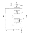
図1は、NO2をNOに変換することによりNOを発生するためのカートリッジ100を示す。該カートリッジ100は、NO発生カートリッジ、GENOカートリッジ又はGENOシリンダとも呼ぶことができ、入口105及び出口110を含む。スクリーン及びグラスウール115が、入口105及び出口110の両方に配置され、該カートリッジ100の残りの部分は、表面活性材料を被覆するために酸化防止剤の飽和水溶液に浸漬した表面活性材料120で充填される。スクリーン及びグラスウール115もまた、該カートリッジ100に挿入される前に酸化防止剤の飽和水溶液に浸漬される。図1の例において、酸化防止剤はアスコルビン酸である。
FIG. 1 shows a
NO2をNOに変換する一般的プロセスにおいて、NO2を有する空気流は入口105を介して受け取られ、該空気流は水性酸化防止剤で被覆された表面活性材料120を経由して出口110まで流体連通される。表面活性材料が湿潤したままであり、かつ酸化防止剤が変換で使い果たされていない限り、該一般的プロセスは、周囲温度でNO2をNOに変換することにおいて有効である。
In the general process of converting NO 2 to NO, an air stream having NO 2 is received via an
入口105は、空気ポンプからのNO2を有する空気流を受け取ることができ、該空気ポンプは、図2のシステム200などにおいて、空気流を、液体NO2を含む透過管を超えて流体連通させる。また入口105は、例えば、NO2タンクとも呼ぶことができる、NO2の加圧ボンベからの、NO2を有する空気流を受け取ることもできる。入口105はまた、窒素(N2)、空気又は酸素(O2)中にNO2を有する空気流を受け取ることもできる。変換は広い濃度範囲にわたって起こる。約2ppmのNO2から100ppmのNO2、及び1000ppmを超えるNO2に至るまでの、空気中の濃度で実験を行った。一実施例において、長さがおよそ15.24cm(6インチ)であり、直径が3.81cm(1.5インチ)のカートリッジに、まずアスコルビン酸の飽和水溶液に浸漬させたシリカゲルを充填した。該湿潤シリカゲルは、Aldrich Chemical社のA.C.S.試薬グレード99.1%純度と指定されたアスコルビン酸(すなわちビタミンC)及びS8 32-1、グレード40のサイズ35から70のメッシュと指定されたFischer Scientific International社のシリカゲルを使用して調製した。他のサイズのシリカゲルも有効である。例えば、0.317cm(1/8インチ)の直径を有するシリカゲルも機能するであろう。
水中35重量%のアスコルビン酸を混合し、攪拌し、及び該水/アスコルビン酸混合物をシリカゲルを通して濾過することによって調製した、アスコルビン酸の飽和溶液を用いてシリカゲルを湿潤させ、続いて脱水した。NO2からNOへの変換は、アスコルビン酸で被覆されたシリカゲルが湿潤しているときに良好に進行することが見出されている。NO2からNOへの変換は、アスコルビン酸の水性溶液単独ではあまり進行しない。 Silica gel was wetted with a saturated solution of ascorbic acid, prepared by mixing 35% by weight ascorbic acid in water, stirring and filtering the water / ascorbic acid mixture through silica gel, followed by dehydration. It has been found that the conversion of NO 2 to NO proceeds well when the silica gel coated with ascorbic acid is wet. The conversion of NO 2 to NO does not proceed much with an aqueous solution of ascorbic acid alone.
湿潤シリカゲル/アスコルビン酸を充填したカートリッジでは、毎分150mlの流量で、12日間に渡り停止せずに、空気中1000ppmのNO2をNOに定量的に変換することが可能であった。毎分わずか数mlから毎分5,000mlの流量までの範囲の、幅広い流量及びNO2濃度の試験に成功した。また反応は、ビタミンEの変異体(例えば、αトコフェロール及びγトコフェロール)など、他の一般的な酸化防止剤を使用しても進行する。 The cartridge filled with wet silica gel / ascorbic acid was able to quantitatively convert 1000 ppm NO 2 in air to NO at a flow rate of 150 ml per minute without stopping for 12 days. We have successfully tested a wide range of flow rates and NO 2 concentrations ranging from just a few ml per minute to a flow rate of 5,000 ml per minute. The reaction also proceeds with the use of other common antioxidants, such as vitamin E variants (eg, α-tocopherol and γ-tocopherol).
該酸化防止剤/表面活性材料のGENOカートリッジは、吸入治療に使用することができる。そのような一実施例において、GENOカートリッジは、加圧ボンベ供給源からNOを送達するNO吸入治療用のNO2スクラバーとして使用することができる。GENOカートリッジを使用して、吸入治療中に化学的に形成される全てのNO2を除去することができる。このGENOカートリッジを使用して、有害レベルのNO2が患者によって不注意に吸入されないように支援することができる。 The antioxidant / surfactant GENO cartridge can be used for inhalation therapy. In one such example, the GENO cartridge can be used as a NO 2 scrubber for NO inhalation therapy that delivers NO from a pressurized cylinder source. Use GENO cartridge, it is possible to remove all of the NO 2 which is chemically formed during inhalation therapy. This GENO cartridge can be used to help prevent harmful levels of NO 2 from being inadvertently inhaled by the patient.
まず、GENOカートリッジを使用して、従来のNO吸入療法において、吸入治療中に使用される安全装置の一部又は全部を補完又は置換することができる。例えば、1つのタイプの安全装置は、NO2の濃度が予め設定された又は所定の制限、通常1ppm以上のNO2を超える場合に、空気中のNO2の存在を警告する。そのような安全装置は、GENOカートリッジが、NOを含んだ空気を吸い込む患者の直前のNO送達システムに配置される場合、不要となり得る。該GENOカートリッジは、患者がNOを含んだ空気を吸い込む直前で全てのNO2をNOに変換し、空気中のNO2の存在を警告する装置を必要なくさせる。 First, the GENO cartridge can be used to supplement or replace some or all of the safety devices used during inhalation therapy in conventional NO inhalation therapy. For example, one type of safety device, NO 2 concentrations preset or predetermined limit, if exceeding the normal 1ppm or more NO 2, to warn of the presence of NO 2 in air. Such a safety device may be unnecessary if the GENO cartridge is placed in a NO delivery system just before the patient inhaling air containing NO. The GENO cartridge converts all NO 2 to NO just before the patient inhales NO-containing air, eliminating the need for a device that warns of the presence of NO 2 in the air.
更に、吸入機器及びガス配管(管機構とも呼ぶことができる)の出口付近に配置されたGENOカートリッジは、換気装置内の通過時間により生じるNO2の形成に関連した問題を低減又は排除する。したがって、GENOカートリッジの使用は、従来の適用において要求される、ガス配管を通るガスの迅速な移動を確実に行う必要性を低減又は排除する。また、GENOカートリッジは、患者への総ガス流量を制御するために、NOガスをガスバルーンとともに使用することを可能にする。 Furthermore, GENO cartridges located near the outlets of inhalation devices and gas pipes (which can also be referred to as pipe mechanisms) reduce or eliminate problems associated with NO 2 formation caused by transit time in the ventilator. Thus, the use of GENO cartridges reduces or eliminates the need to ensure rapid movement of gas through gas piping, as required in conventional applications. The GENO cartridge also allows NO gas to be used with a gas balloon to control the total gas flow to the patient.
あるいは又は加えて、患者への送達システム取り付けの直前にNO2除去カートリッジを挿入して、更に安全性を高め、微量の有毒なNO2が全て除去されていることを支援することができる。該NO2除去カートリッジは、どんなに微量なNO2をも除去するために使用されるGENOカートリッジとすることができる。あるいは、該NO2除去カートリッジは、加熱活性化アルミナを含むことができる。Fisher Scientific International社によって供給されるような、A505-212、8〜14のメッシュサイズと指定される加熱活性化アルミナを有するカートリッジは、空気又は酸素の流れから低レベルのNO2を除去するのに有効であり、更にNOガスを損失なく通過させる。活性化アルミナ、及びそれと同様の他の高表面積材料は、NO吸入管からNO2を洗浄するために使用することができる。 Alternatively or additionally, a NO 2 removal cartridge can be inserted just prior to the delivery system being attached to the patient to further increase safety and assist in removing all traces of toxic NO 2 . The NO 2 removal cartridge can be a GENO cartridge used to remove any trace amount of NO 2 . Alternatively, the NO 2 removal cartridge can include heat activated alumina. As supplied by Fisher Scientific International, Inc., the cartridge having a heat activated alumina designated mesh size A505-212,8~14, for removing low levels of NO 2 from a stream of air or oxygen It is effective and allows NO gas to pass through without loss. Activated alumina, and other high surface area materials similar thereto, can be used to clean NO 2 from the NO inlet tube.
別の実施例において、GENOカートリッジを使用して、治療用ガス送達のためのNOを発生することができる。該NO発生カートリッジは、周囲温度で有害なNO2をNOへと変換するのに有効であるので、液体NO2をNOの供給源として使用することができる。NO発生の供給源として液体NO2が使用される場合、送達システムにNOガスを供給するための加圧ガスボンベは不要である。そのような送達システムの一例を図2について、より詳細に説明する。NO提供のための加圧ガスボンベの必要性を排除することにより、該送達システムは、NOガスの加圧ガスボンベから患者へNOガスを送達するのに使用される従来の装置と比較して、簡易化することができる。加圧ガスボンベを使用しないNO送達システムは、加圧ガスボンベに依拠する従来のシステムよりも可搬性を増すことができる。 In another example, a GENO cartridge can be used to generate NO for therapeutic gas delivery. Since the NO generating cartridge is effective in converting harmful NO 2 to NO at ambient temperature, liquid NO 2 can be used as a source of NO. When liquid NO 2 is used as a source for NO generation, a pressurized gas cylinder for supplying NO gas to the delivery system is not required. An example of such a delivery system is described in more detail with respect to FIG. By eliminating the need for a pressurized gas cylinder to provide NO, the delivery system is simpler than conventional devices used to deliver NO gas from a pressurized gas cylinder of NO gas to a patient. Can be NO delivery systems that do not use pressurized gas cylinders can be more portable than conventional systems that rely on pressurized gas cylinders.
図2〜図14は、GENOカートリッジにおいて用いられる表面活性材料として、シリカゲルを使用する技術を示す。先に記載したように、シリカゲルは、NO発生システム又はカートリッジにおいて使用することができる表面活性材料の一例に過ぎない。 2-14 illustrate a technique that uses silica gel as the surface active material used in the GENO cartridge. As described above, silica gel is just one example of a surface active material that can be used in a NO generation system or cartridge.
図2は、液体NO2をNOガスに変換に変換し、次いで、これをNO吸入治療のために患者に送達することができる、NO発生システム200を示す。一般に、空気ポンプ205によって生み出される空気の流れは、液体NO2及びその二量体N2O4(まとめて236)を有するガス透過セル235を経由して進行する。ガス透過セル235を出た空気流はガス状のNO2を含み、該ガス状のNO2は、NO発生カートリッジ240によってNOガスに変換される。NOガス混合物は吸入治療のために、例えば、マスク、カニューレ又はベンチレータを使用して患者へと送達することができる。患者へと送達されるNOガス混合物中のNO濃度は、ガス透過セル235の温度を制御するか、又は流量計220を通る空気流量を制御することによって制御することができる。
FIG. 2 shows a
より具体的には、システム200は、空気ポンプ205、調整器210、流れ転向装置215及び流量計220を含む。該システムは、空気ポンプ205からの空気流207が、150ml/分の第1の流れ225と、3000ml/分の第2の流れ230とに分流されるように構成される。空気流207は、乾燥性か又は湿潤性であってもよい。
More specifically,
流れ225は、液体NO2及びその二量体N2O4(まとめて236)、並びにガス透過管237を含むガス透過セル235を経由して進行する。該透過セル235はまた、透過発生器、透過装置又は透過管ホルダとも呼ぶことができる。NO2はガス透過セル235のガス多孔質膜を通過して、流れ225へと拡散する。一実施例において、150ml/分の空気の流れ225は、透過管237、例えば、テキサス州オースティンのKinTek社によって提供される透過管を通過して流れることが可能である。透過管237は、該透過管237が40℃の温度である場合に、流れ225において透過管を後にするガス流が約840ppmのNO2を含むように、定常的な速度でNO2を放出するように設計される。領域238は、およそ40℃の温度を維持するように温度制御される。下記により詳細に記載するように、透過セル235の温度を維持することは、患者に送達されるNOの濃度を制御するのに役立つ。
次に、840ppmのNO2を含む150mlの空気は、NO発生カートリッジ240を通過して流れる。この実施例において、NO発生カートリッジ240は、長さ15.24cm(6インチ)、直径3.81cm(1.5インチ)であり、変換試薬として働くシリカゲル上の湿潤アスコルビン酸を含む。NO発生カートリッジ240は、図1のカートリッジ100の一実施態様であり得る。該NO発生カートリッジ240を出た空気流225は、NO2の全部又は実質的に全部がNOに変換された840ppmのNOを含む。
Next, 150 ml of air containing 840 ppm NO 2 flows through the
次いで、該840ppmのNOを有する150ml/分の流れ225は、3000ml/分の空気又は酸素の流れ230と混合し、40ppmのNOを含む3150ml/分の流れ247が生成される。混合後、流れ247は、第2のNO発生カートリッジ245を通過して進行し、流れ225と230とが混合される場合に、NOが希釈される間に形成され得る全てのNO2を除去する。NO発生カートリッジ240及び245は、必ずしもそうである必要はないが、同じサイズであってもよい。例えば、NO発生カートリッジ245は、NO発生カートリッジ240よりも小さいNO2変換能力を有するサイズであってもよい。次いで、得られたNOを有する空気流250は、患者に送達できる状態となっている。システム200は、数時間の短期間又は14日以上の長期間の間、NOガスの定常的な流れを生成するように設計することができる。一試験において、システム200は、NO2を含まない、空気中40ppmのNOガスの定常的な流れを12日間に渡って送達することを示した。ここで、該NO及びNO2の濃度は、化学発光ガス分析装置によって測定した。
The 150 ml /
システム200の代替として、NO発生システムは、透過管237よりも大きな流れ容量を有する透過管を含むことができる。そのような場合、該より大きな透過管は、患者への送達に必要な吸引用空気の全てを処理することができ、例えば、流れ230及び変換管245が不要となる。
As an alternative to the
システム200は、例えば、空気の供給に使用される空気ポンプ205が、簡易オイルレスポンプなどの可搬式空気ポンプである場合に、可搬式にすることができる。酸素富化空気が患者に必要とされる場合、空気ポンプ205によって供給される空気に加えて、又はその代わりに、酸素を供給することができる。例えば、酸素は酸素タンク又は市販の酸素発生装置から供給することができる。また酸素は、O2と混合されたNO2を有するタンクから供給することもできる。
The
いくつかの実施態様において、透過セル238及び/又は2つの変換カートリッジ240及び245は、使い捨て可能な物品とすることができる。
In some embodiments, the
システム200を出る流れ250中のNOの濃度は、流れ225が毎分数ミリリットルを上回る限り、透過セル235を通過する流れ225に左右されない。該流れ250中のNOの濃度は、透過セル235の温度によって変わり、より低い程度ではあるが空気流量230によっても変わる。例えば、一定の空気流量230で、システム200は、40℃の温度で40ppmのNOを送達するように設計されるが、該NOの濃度は、30℃で20ppmのNOに低下させることができ、50℃で80ppmに増大させることができる。したがって、温度制御装置を使用して、送達されるNOガスの濃度を調整することができる。所望のNO濃度を選択し、該温度制御装置を、該所望の濃度を送達するための特定温度を維持するように設定すると、所望の濃度のNOガスの送達速度は、一定に維持される。該温度制御装置の一例は、オーブン、例えば、KinTek社から入手可能なオーブンであり、その中に透過管が配置される。温度制御装置の別の例は、ホットプレート上に配置されたビーカー中の脱イオン水であり、透過管は該ビーカー内に配置される。水温を監視するために、該ビーカー内に温度計を配置してもよい。
The concentration of NO in
該NO発生システムを使用して、カニューレを用いる使用のために、NOガス混合物の定常的な流れを送達することができ、過剰なガスは環境へと排出される。NO発生システムは、ベンチレータとともに使用することができ、そのような場合、NO発生器からの送達は定常性を維持しなければならず、かつNOを受け取る患者を危険にさらすことなく遮断することはできない。患者の吸気中に流れを増大させる必要性に対処するために、可撓性バッグを膨張させ、次いで収縮させるのにNOガス混合物を使用することができる。患者への空気流が少しでも遅延される場合、NO発生カートリッジをNO発生システムの吸入直前の地点に挿入し、そのような遅延中にNOとO2との反応により形成され得る全てのNO2を除去することができる。これは、該遅延間にバッグ中で形成され得るNO2がどんなに微量であっても、治療用ガス流が患者によって吸引される前に確実に除去されることに役立つ。 The NO generation system can be used to deliver a steady flow of NO gas mixture for use with a cannula, with excess gas being vented to the environment. The NO generation system can be used with a ventilator, in which case delivery from the NO generator must remain stationary and can be blocked without endangering the patient receiving the NO. Can not. To address the need to increase flow during patient inspiration, a NO gas mixture can be used to inflate and then deflate the flexible bag. If any airflow to the patient is delayed, insert a NO generation cartridge at a point just prior to inhalation of the NO generation system, and any NO 2 that can be formed by the reaction of NO and O 2 during such a delay. Can be removed. This helps to ensure that no matter how much NO 2 can be formed in the bag during the delay, the therapeutic gas stream is removed before it is aspirated by the patient.
治療用ガス送達システム200中に検出器を含み、治療用ガス流内のNO濃度を検出することができる。該検出器はまた、必要に応じて、治療用ガス中のNO2濃度を検出することもでき、NO濃度が所定の範囲外にあるか又はNO2濃度が閾値を超えている場合に、警告を与えることができる。監視技術の例を挙げると、化学発光及び電気化学的技術がある。一酸化窒素の存在は、例えば、化学発光検出器によって検出することができる。
A detector may be included in the therapeutic
図3は、液体NO2をNOガスに変換し、次いで、NO吸入治療のために患者に送達することができる、NO発生システム300を示す。図2のNO発生システム200とは対照的に、NO発生システム300は、活性アルミナカートリッジ345を含む。活性アルミナカートリッジ345は、遅延中に形成される全てのNO2を除去する。NO2をNOに変換すること、及びそれによって定量的にNO2の損失を補うことによってNO2を除去するNO発生カートリッジ240とは対照的に、活性アルミナカートリッジ345は、NOを発生することなくプロセスガス流からNO2を除去する。
FIG. 3 shows a
図4に、図1のNO発生カートリッジ100の一実施態様であり得るNO発生カートリッジ440を使用する治療用ガス送達システム400を示す。システム400は、NO供給源410を使用して、管機構を介して流れ420中のガス状NOを提供する。一実施例において、NO供給源410は、NOの加圧ボンベとすることができる。管機構を通る空気の流れ430は、空気ポンプ435によって生み出され、流れ420と混合される。NO発生カートリッジ440へと入る空気流は、ガス状NOを含む。流れ420中で形成されたNO2ガスは全て、NO発生カートリッジ440によって除去される。NO発生カートリッジ440を出た空気流450は、治療用NOガスを含むが、有毒なレベルのNO2は含まない。次いで、空気流450は、NO吸入治療の患者に送達され得る。
FIG. 4 shows a therapeutic
図5に、図1のNO発生カートリッジ100の一実施態様であり得るNO発生カートリッジ540を使用する治療用ガス送達システム500を示す。図4の治療用ガス送達システム400とは対照的に、システム500は、NO2供給源510からNOを発生する。NO2供給源510は、NO2供給源510を出た流れ525がガス状NO2を含むように、空気ポンプ520によって生み出された空気流515への液体NO2の拡散を使用することができる。いくつかの実施態様において、NO2供給源510は、NO2の加圧ボンベとすることができる。
FIG. 5 shows a therapeutic
いずれの場合においても、NO発生カートリッジ440に入る空気流525は、ガス状NO2を含む。NO発生カートリッジ440は、流れ525中のNO2ガスをNOに変換する。NO発生カートリッジ540を出た空気流550は、治療用NOガスを含むが、NO2を含まないか又は実質的に含まない。次いで、空気流550は、NO吸入治療の患者に送達され得る。
In either case, the
図6に、治療用ガスを送達するための、GENO加圧タンクシステム600を示す。システム600は、空気中40ppmのNO2を有する市販のタンク620及び流量制御装置622を含む。タンク620の一例では、300立方フィートのタンクが、5L/分の空気流量で1.2日間持続する。
FIG. 6 shows a GENO pressurized
空気中NO2の空気流625aは、流量制御装置622を出てGENOカートリッジ640に入る。GENOカートリッジ640は、前駆物質としてNO2を使用し、NO2をNOに変換する。GENOカートリッジ640を出た空気流625bは、治療用NOガスを含む。空気流625bは活性アルミナカートリッジ660に入り、空気流625b中の全てのNO2が除去される。活性アルミナカートリッジ660を出た空気流625cは、NO吸入治療の患者に送達される。
An
システム600は、NOxサンプルバルブ665、及びNO2の検出に動作可能なNO-NO2センサ670を含む。NO-NO2センサはまた、NO-NO2検出器と呼ぶこともできる。NOxサンプルバルブ665は、空気流667a及び667bからNO-NO2センサ670に空気サンプルを与えるように動作可能である。NO-NO2検出器670を使用して空気流667a中のNO2の存在を検出することによって、GENOカートリッジ640の不具合の指標を提供することができ、したがって、有毒なNO2が患者に送達されることがないように細心の安全装置を提供する。
いくつかの実施態様において、活性アルミナカートリッジ660は、GENOカートリッジで置換することができる。
In some embodiments, the activated
いくつかの実施態様において、GENOカートリッジは、ガスボンベからの出力口がGENOカートリッジにのみ接続できるように、特別なネジ筋を有する加圧ガスボンベの出力口に取り付けられる。例えば、該ガスボンベは、約10〜100ppmの濃度のNO2を含む吸気可能な酸素ガスで充填されていてもよい。そのようなシステムは、ガスボンベの圧力を使用して治療用ガスを患者に送達することができ、かつ駆動部、電子機器又はポンプを有さなくてもよい。あるいは、該ガスボンベは、NO2を含む空気で充填されていてもよい。加圧ガスボンベ中の空気又は酸素ガスの使用は、混合、及び濃縮NOガスを治療用量まで安全に希釈するのに必要な装置を要する、不活性窒素ガス中のNOを供給する従来の方法を上回る利点を提供する。 In some embodiments, the GENO cartridge is attached to the output port of a pressurized gas cylinder with special threads so that the output port from the gas cylinder can only be connected to the GENO cartridge. For example, the gas cylinder may be filled with inhalable oxygen gas containing NO 2 at a concentration of about 10-100 ppm. Such a system can use gas cylinder pressure to deliver therapeutic gas to the patient and may not have a drive, electronics or pump. Alternatively, the gas cylinder may be filled with air containing NO 2 . The use of air or oxygen gas in a pressurized gas cylinder exceeds conventional methods of supplying NO in inert nitrogen gas, which requires mixing and the equipment necessary to safely dilute the concentrated NO gas to a therapeutic dose. Provides benefits.
図7に、治療用ガスを送達するための、GENO高濃度NO2加圧システム700を示す。図6のシステム600とは対照的に、システム700は、2つのGENOカートリッジ740及び750、並びに、GENOカートリッジ740又は750のどちらを使用するかを制御するための切換バルブ745を含む。NO-NO2検出器770が、使用中のGENOカートリッジを出た空気流725d中にNO2の存在を検出すると、切換バルブ745を操作して、空気流725cがもう一方のGENOカートリッジ740又は750を通過するように切り替えることができる。第1のGENOカートリッジが故障した場合に、第2のGENOカートリッジへと切り替えるその能力は、治療用ガスが送達されている患者に更なる安全の階層を提供する。
FIG. 7 shows a GENO high concentration NO 2 pressurization system 700 for delivering therapeutic gas. In contrast to the
より具体的には、システム700は、空気中1000ppmのNO2を有するタンク720、及び流量制御装置722を含む。該実施例において、タンク720は、2250psiにて150立方フィートであるタンクであり、125cc/分の空気流を提供する。患者に送達される40 ppm、5L/分の空気流で、タンク720はおよそ23日間持続する。タンク720は、GENOカートリッジ740及び750の各々の予想される耐用期間よりも長い期間、空気流を供給することができ、この実施例に使用されるカートリッジにおける耐用期間は、2週間未満である。したがって、1つのGENOカートリッジから別のGENOカートリッジへと切り替える能力は、確実にタンクの内容物を使用する又は実質的に使用するのに役立つ。
More specifically, the
空気中NO2の空気流725aは、流量制御装置722を出て、空気ポンプなどの空気供給源730によって生み出された5L/分の空気流725bと混合される。得られた空気流725cは、切換バルブ745に入る。切換バルブ745は、GENOカートリッジ740又は750のどちらが空気流725cを受け取るかを制御する。示されるように、切換バルブ745は、空気流725cがGENOカートリッジ750に供給されるように設定される。GENOカートリッジ750は、空気流725c中のNO2をNOに変換する。GENOカートリッジ725dを出た空気流725dは、治療用NOガスを含む。空気流725dは活性アルミナカートリッジ760に入り、空気流725d中の全てのNO2が除去される。活性アルミナカートリッジ760を出た空気流725eは、NO吸入治療の患者に送達される。
The air stream 725a of NO 2 in the air exits the
システム700は、NOxサンプルバルブ765、及びNO2を検出するように動作可能なNO-NO2センサ770を含む。NOxサンプルバルブ765は、空気流767a及び767bからの空気サンプルを、NO-NO2センサ770へ提供するように動作可能である。NO-NO2センサ770を使用して、空気流767a中のNO2の存在を検出することは、第2のGENOカートリッジを使用することができるように、使用中のGENOカートリッジの故障の指標を提供することができる。いくつかの実施態様において、活性アルミナカートリッジ760は、GENOカートリッジで置換することができる。
図8に、治療用ガスを送達するための、GENO高濃度NO2カートリッジシステム800を示す。図6及び図7のそれぞれのシステム600又は700とは対照的に、システム800は、NOの発生に使用されるNO2の供給源として、高濃度NO2カートリッジを含む。より詳細には、システム800は、NO2カートリッジ800、例えば、小型のブタンタンク又はCO2を送達するのに従来使用されるカートリッジなどを含む。システム800の一実施例において、2.54cm(1インチ)×15.24cm(6インチ)の寸法を有し、CO2中の5%のNO2で充填されたNO2カートリッジは、14日間NO2を送達することが可能であった。
FIG. 8 shows a GENO high concentration NO 2 cartridge system 800 for delivering therapeutic gas. In contrast to the
NO2遮断バルブ821は、カートリッジ800に隣接して、カートリッジ800からのNO2の送達を遮断する。またシステム800は流量制御装置822を含み、ほぼ一定流量の流れ825aが流量制御装置822から出るようにする。流量制御装置822は、ガス流825aがそこを通過する小さい穴を有するガラス管である。システム800の様々な実施態様において、流量制御装置822は、1〜10cc/分の一定流量を確実にすることができる。
The NO 2 cutoff valve 821 blocks the delivery of NO 2 from the
NO2を有するガス流825aは、流量制御装置822を出て、空気供給源830によって生み出されたおよそ5L/分の空気流825bと混合される。ガスミキサ835は、空気流825a及び825bが十分に(又は実質的に十分に)混合されることを確実にする。得られたNO2を有する空気流825cは、NOを発生するGENOカートリッジ840に入る。
The
またシステム800は、活性アルミナカートリッジ860を含み、NOを含む治療用ガスがおよそ5L/分の速度で患者に送達される前に、全てのNO2が取り除かれる。システム800は、NOxサンプルバルブ865、及びNO2を検出するように動作可能なNO-NO2センサ870を含む。いくつかの実施態様において、活性アルミナカートリッジ860を、GENOカートリッジで置換することができる。
The
図9に、治療ガスを送達するためのGENO透過システム900を示す。システム900は、GENOカートリッジ940に流れるおよそ5L/分の空気流925aを含み、該カートリッジは空気を加湿するように作用する。GENOカートリッジ940を出た後、空気流925aは、空気流925bが透過装置935を通過し、かつ空気流925cが通過しないように分離する。透過装置935は、透過管機構937、及び空気流925aの開始時に約10ccの液体NO2936を含む。透過装置935は、図2の透過セル235の一実施態様であり得る。透過装置935は、透過オーブン939内に位置し、所望の濃度のNO2が空気流925bに拡散することを確実にするために、一定の又は実質的に一定の温度を維持する。空気流925b及び空気流925cは、GENOカートリッジ950に入る前に、混合して流れ925dを形成する。GENOカートリッジ950はNO2をNOに変換する。
FIG. 9 shows a
システム900はまた、活性アルミナカートリッジ960を含み、該カートリッジは、空気流925eを受け取り、NOを含む治療用ガスがおよそ5L/分の流速で患者に送達される前に全てのNO2を除去する。該活性アルミナカートリッジを出た空気流925fは、NO吸入治療の患者に送達される。システム900は、NOxサンプルバルブ965、及びNO2を検出するように動作可能なNO-NO2センサ970を含む。
The
図10に、治療用ガスを送達するためのGENO透過システム1000を示す。図9のシステム900とは対照的に、システム1000は、GENOカートリッジ1040及び1050のどちらが最初に空気流を受け取るかを制御するためのバルブ1010及び1015を含む。システム1000は、NOに変換されるNO2供給源として、透過装置1035中の液体NO2を使用する。システム1000はまた、活性化アルミナカートリッジ1060を含み、NOを含む治療用ガスがおよそ5L/分の流量で患者に送達される前に、全てのNO2を除去する。またシステム1000は、NOxサンプルバルブ1065、及びNO2を検出するように動作可能なNO-NO2センサ1070を含む。
FIG. 10 shows a
システム1000は、バルブ1010へのおよそ5L/分の空気流1025aを受け取り、バルブ1010は、バルブ1015とともに、空気流1025aがGENOカートリッジ1040又は1050のどちらを最初に通過するかを制御する。より具体的には、バルブ1010及び1015の位置を制御することによって、空気流1025aは、GENOカートリッジ1040、透過装置1025、GENOカートリッジ1050、次いで、活性化アルミナカートリッジ1060を通過させることができ、その後、患者に送達される。バルブ1010及び1015の位置を操作することによって、空気流1025aはまた、GENOカートリッジ1050、透過装置1025、GENOカートリッジ1040、次いで、活性化アルミナカートリッジ1060を通過させることができ、その後、患者に送達される。
例えば、NO-NO2センサ1070が空気流1025b中にNO2の存在を検出すると、該センサは、バルブ1010及び1015を操作することの必要性の信号を送り、GENOカートリッジ1040及び1050を切り替えて使用するという命令を与える。すなわち、例えば、空気流1025aがGENOカートリッジ1040を通過し、その後、後続のGENOカートリッジ1050を通って流れている場合、バルブ1010及び1015を操作して、空気流1025aがGENOカートリッジ1050を通過し、その後、後続のGENOカートリッジ1040を通って流れるようにさせる。
For example, if the NO-NO 2 sensor 1070 detects the presence of NO 2 in the
いくつかの市販の適用において、NO2は酸素又は空気中およそ10〜100ppmの所定の濃度で販売され得る。 In some commercial applications, NO 2 may be sold at a given concentration of approximately 10~100ppm oxygen or air.
図11は、NO2をNOに変換する、GENOカートリッジ1100の概念的デザインを示す。GENOカートリッジ1100は、図1のカートリッジ100の一実施態様であり得る。GENOカートリッジ1100は、長さおよそ15.24cm(6インチ)、直径2.54cm(1インチ)である。GENOカートリッジ1100は、アスコルビン酸の水性溶液で飽和されたシリカゲルを含み、NO2を含む空気又は酸素ガスボンベから空気流を受け取る。カートリッジ1100を通る空気流は、NO2をNOに変換され、カートリッジ1100を出る。GENOカートリッジ1100は、5ppmから5000ppmのNO2濃度で有効に機能する。GENOカートリッジ1100を用いるNO2からNOへの変換は、熱源を必要とせず、かつ周囲空気温度で使用することができる。GENOカートリッジ1100を用いたNO2からNOへの変換は、GENOカートリッジ1100を通過する空気流の流量とは実質的に無関係に起こる。
FIG. 11 shows a conceptual design of a
図12に、NO2を含むガスボンベ1220及びGENOカートリッジ1210を含む治療用ガス送達システム1200を示す。GENOカートリッジ1210は、ガスボンベ1220からのNO2をNO吸入治療の患者に送達するNOへ変換するための、図11のGENOカートリッジ1100の一実施態様であり得る。システム1200は、可搬式となるように設計される。いくつかの実施態様において、システム1200は、電子機器又はセンサを使用することなく動作するよう設計することができる。ガスボンベ1220の容量に応じて、一般にシステム1200は、治療用NOガスを1から16時間送達する能力を有する。
FIG. 12 shows a therapeutic
システム1200は、緊急体制における患者への治療用NOガスの送達に用いることができる。そのような状況の例を挙げると、緊急医療隊員、衛生兵又は野戦病院、消防士、救急隊員、及び病院の救急治療室又は外傷センターによる使用がある。別の例として、可搬式治療用NOガス送達装置は、酸素富化空気で呼吸している困窮した登山者を援助するのに使用することができる。更に別の例において、可搬式治療用NOガス送達装置は、主要NO供給源が故障している患者に使用することができる。いくつかの実施態様において、可搬式治療用NOガス送達装置は、一度限りの使用として設計することができる。
図13Aに、液体NO2供給源を有する治療用ガス送達システムの外観1300Aを示す。図13Bは、図13Aに示した治療用ガス送達システムの内部図1300Bを示す。該治療用ガス送達システムは、液体NO2供給源を有する透過管1310を含み、透過管1310は、例えば、図9の透過装置935の一実施態様であり得る。該治療用ガス送達システムはまた、GENOカートリッジ1340及び1350を含む。GENOカートリッジ1340は、空気又は酸素供給源からの空気流1325aを受け取る。GENOカートリッジ1340を出た後、空気流は、およそ10%の空気流が透過管1310を通過して流れ、これにより気体状NO2が該空気流中に拡散するように分離される。透過管1310を出た空気流、及び透過管1310を通らなかったその他の空気流は、NO2をNOに変換するGENOカートリッジ1350を通過して流れる。GENOカートリッジ1350を出た空気流1325b及び1325cは、NO吸入治療の患者に送達される。透過管1310、並びにGENOカートリッジ1340及び1350は、使い捨てとすることができる。
FIG. 13A shows an
透過管1310の容量に応じて、図13A及び図13Bに示した治療用ガス送達システムは、1〜30日間の治療用NOガス送達能力を有し得る。
Depending on the capacity of the
図13A及び図13Bに示した治療用ガス送達システムは、ベンチレータと連動することができる。また図13A及び図13Bに示した治療用ガス送達システムを用いて、カニューレを使用した患者への治療用NOガス送達を行うことができる。例えば、毎分2リッターの流量で、該治療用NOガスの送達をカニューレを通して提供することができる。カニューレを用いる治療用ガス送達システムの使用により、NO治療を病院環境外で行うことを可能にする。そのような例の1つは、患者の自宅で行われる長期のNO治療のための治療用ガス送達システムの使用である。 The therapeutic gas delivery system shown in FIGS. 13A and 13B can work with a ventilator. The therapeutic gas delivery system shown in FIGS. 13A and 13B can also be used to deliver therapeutic NO gas to a patient using a cannula. For example, delivery of the therapeutic NO gas can be provided through a cannula at a flow rate of 2 liters per minute. The use of a therapeutic gas delivery system with a cannula allows NO treatment to be performed outside the hospital environment. One such example is the use of a therapeutic gas delivery system for long-term NO treatment performed at the patient's home.
図13Cに、炭酸飲料の缶1350と比較した、図13A及び図13Bに示した治療用ガス送達システムの外観1300Aを示す。図示のように、図13A〜図13Cに示した治療用ガス送達システムの実施態様は、従来のNO吸入治療システムに比べて小型の装置であり、炭酸飲料の缶よりもわずかに大きい。 FIG. 13C shows the exterior 1300A of the therapeutic gas delivery system shown in FIGS. 13A and 13B compared to a carbonated beverage can 1350. FIG. As shown, the therapeutic gas delivery system embodiment shown in FIGS. 13A-13C is a small device compared to a conventional NO inhalation therapy system and slightly larger than a carbonated beverage can.
図14に、GENOカートリッジを使用してNO2をNO吸入治療で使用するためのNOに変換する、治療用ガス送達システム1400の外観を示す。システム1400は、GENOカートリッジを挿入又は接続できるGENOカートリッジポート1410及び1415を含む。システム1400は、空気又は酸素がそれを通ってシステム1400へ流入する入口ポート1420及び付属の計器1425を含む。システム1400は、空気流を制御するための、フロー値1430及び表示器1435を含む。システム1400は、GENOカートリッジフローポート1440を含む。
FIG. 14 shows the appearance of a therapeutic
またシステム1400は、温度制御装置1445、及びNOx検出器アクセス1455によりアクセス可能なNOx検出器1450を含む。システム1400はまた、GENOカートリッジ1460を含み、カートリッジ1460は、基本的にNOを有する空気流が出口1465を通りシステム1400を出る直前で、NO2をNOに変換するために使用される。GENOカートリッジ1460は、安全スクラバーと呼ぶこともできる。GENOカートリッジ1460は、システム1400の他の部分で使用されるGENOカートリッジよりも小さくてもよい。またシステム1400は、バックアップ入力ポート1470及び排気ファン1475を含む。
The
(更なる例示的実施態様)
これら更なる例示的実施態様は、酸素又は空気又はいくつかの組合せ中にNO2として貯蔵された、必要用量のNOを含むガスボンベを使用する。ガスはガスボンベからの放出において、下記のように変換される。
正 2NO2→2NO+O2
(Further exemplary embodiments)
These further exemplary embodiments use gas cylinders containing the required dose of NO stored as NO 2 in oxygen or air or some combination. The gas is converted as follows upon release from the gas cylinder.
Positive 2NO 2 → 2NO + O 2
この反応は、GENOカートリッジにおいて、湿潤シリカゲルマトリックスのアルコルビン酸上にて1秒未満で起こる。システムの圧力は、ガスが該システムを通過するのに必要な力を維持しなければならない。通常、該力は約0.001〜50psi、例えば、0.001〜0.1又は0.001〜0.05psiである。一実施態様において、該システムの圧力は、毎分5リッター程度の低流量で、大気圧より上で、0.005psiの圧力損失とすることができる。別の実施態様において、圧力損失は、毎分60リッターの高さのガス流で、0.04psiとすることができる。更なる実施態様において、GENOカートリッジは、大気圧より上で、約15〜約25psiで良好に作動することができる。NOが形成されるとすぐに、下記のすなわち逆反応が起こる。
逆 NO+NO+O2→2NO2
This reaction occurs in less than 1 second on the ascorbic acid of a wet silica gel matrix in a GENO cartridge. The system pressure must maintain the force necessary for the gas to pass through the system. Typically, the force is about 0.001 to 50 psi, such as 0.001 to 0.1 or 0.001 to 0.05 psi. In one embodiment, the system pressure can be as low as 0.005 psi above atmospheric pressure with a flow rate as low as 5 liters per minute. In another embodiment, the pressure drop can be 0.04 psi with a gas flow as high as 60 liters per minute. In a further embodiment, the GENO cartridge can perform well at about 15 to about 25 psi above atmospheric pressure. As soon as NO is formed, the following reaction occurs:
Reverse NO + NO + O 2 → 2NO 2
圧力が高いほど、より速くこの反応が起こる;実際、その速度は圧力について3次である。調整器の高圧側でのNO2からNOへの変換は、逆反応が正反応とほぼ同じ速さで起こっている場合には起こらない。この問題に対処するために、圧力調整器の低圧側にGENOカートリッジを設置することによって逆反応を最小化する。これを下記図16に示す。ガスはガスボンベを出て、調整器を通過し、次いで、第1のカートリッジを下り接続管まで流れ、次に、第2のカートリッジに流れ、次いで、外へ出て使用者へと流れる。 The higher the pressure, the faster this reaction takes place; in fact, the rate is third order with respect to pressure. The conversion of NO 2 to NO on the high pressure side of the regulator does not occur when the reverse reaction occurs at about the same rate as the forward reaction. To counter this problem, the reverse reaction is minimized by installing a GENO cartridge on the low pressure side of the pressure regulator. This is shown in FIG. The gas exits the gas cylinder, passes through the regulator, then flows through the first cartridge to the downcomer tube, then into the second cartridge, and then exits to the user.
2つのカートリッジを、順々に、直列で使用する。その理由は、2重のリダンダンシーを与えることにある。1つのカートリッジで十分に機能するが、第2のカートリッジを有することでリダンダンシーを与える。各カートリッジは、100ppmで40%の余剰容量から20ppmに対して20×の余剰容量までのガスボンベの全内容物を捕捉するように大きさが設定されている。したがって、この例示的実施態様は、2つの同一のカートリッジを使用し、1つのカートリッジだけを使用する時の2倍のバックアップを提供する。 Two cartridges are used in series, one after the other. The reason is to give double redundancy. One cartridge works well, but having a second cartridge provides redundancy. Each cartridge is sized to capture the entire contents of the gas cylinder from 40% surplus capacity at 100 ppm to 20 × surplus capacity for 20 ppm. Thus, this exemplary embodiment uses two identical cartridges and provides twice the backup when using only one cartridge.
(操作と安全性)
システムの使用の安全性を向上させる別の方法は、ガスボンベのカバーの一体部分としてカートリッジを収めることである。これを調整器とともに下記図17に示す。
(Operation and safety)
Another way to increase the safety of use of the system is to house the cartridge as an integral part of the cover of the gas cylinder. This is shown in FIG.
そのような実施態様において、使用者はガスボンベを受け取り、次いで、特殊な調整器をガスボンベに取り付ける。特別に固定されたCGA継手を使用することで、GENO調整器だけが使用され得る。しかし、調整器の出力口は、ガスボンベのカバーに取り付けられたGENOカートリッジへの導入口になるように形成されてもよい。このように、使用者がボンベから排出されるガスを得ることができる唯一の方法は、特別なCGA継手を有する調整器を使用することであり、かつ該調整器から出てくるガスを得る唯一の方法は、GENOカートリッジに接続することである。このように、ガスボンベから出ているガスだけが、GENOカートリッジを通過することができる。 In such an embodiment, the user receives the gas cylinder and then attaches a special regulator to the gas cylinder. By using specially fixed CGA fittings, only GENO regulators can be used. However, the output port of the regulator may be formed so as to serve as an introduction port to the GENO cartridge attached to the cover of the gas cylinder. Thus, the only way a user can get the gas exhausted from the cylinder is to use a regulator with a special CGA fitting, and the only way to get the gas coming out of the regulator The method is to connect to the GENO cartridge. In this way, only gas exiting from the gas cylinder can pass through the GENO cartridge.
これを図18に示す。カートリッジは、常にガスボンベとともにある。例えば、ボンベを補充するために返却する場合でさえも、使用したカートリッジは、該ガスボンベに残されたままである。ガス充填に次いで、使用済みカートリッジを取外し、使用済みカートリッジと新しいカートリッジとを取り替える。 This is shown in FIG. The cartridge is always with the gas cylinder. For example, used cartridges remain in the gas cylinder even when returned to refill the cylinder. Following gas filling, the used cartridge is removed and the used cartridge is replaced with a new cartridge.
図18に、ガスボンベの出口及びカートリッジの入口に接続された調整器を示す。
更なる安全性のために、カートリッジからの出力は、酸素ガス中のNOが特別な補助器具を用いてのみ使用できるように、同様に鍵をかけることができる。
FIG. 18 shows the regulator connected to the outlet of the gas cylinder and the inlet of the cartridge.
For added safety, the output from the cartridge can be similarly locked so that NO in oxygen gas can only be used with special aids.
NOガスの濃度を変更するためには、異なるガスボンベを使用する。ガスボンベ中のNOガス濃度の特定に有用な1つの方法は、各濃度のボンベに異なる色をもたせることである。例えば、20ppmの濃度を有するボンベを青とし、対して100ppmの濃度を有するボンベを赤とする。各濃度は、それ自身の特別な鍵のついたガスボンベを有することができ、それはまた、使用する目的の濃度と異なったNOガス濃度を、意図せず使用することを減少させる、又はそれを防止するのに役立ち得る。ガスボンベの取り違えを防止するために、例えば、100ppmの濃度を有するボンベはある場所でボンベに充填されるのに対し、20ppmの濃度のボンベは異なった場所でボンベに充填されるなど、異なる濃度を異なる場所でボンベに充填してもよい。 Use different gas cylinders to change the concentration of NO gas. One useful method for determining the NO gas concentration in a gas cylinder is to have a different color for each concentration cylinder. For example, a cylinder having a concentration of 20 ppm is blue, whereas a cylinder having a concentration of 100 ppm is red. Each concentration can have its own special key gas cylinder, which also reduces or prevents unintentional use of NO gas concentrations that differ from the intended concentration used. Can help to. To prevent gas cylinders from being mixed up, for example, a cylinder with a concentration of 100 ppm is filled in a cylinder at one location, while a cylinder with a concentration of 20 ppm is filled in a cylinder at a different location. The cylinders may be filled at different locations.
いくつかの実施態様において、カートリッジの構造は3部分のみを含み得る。第1の部分は、図19に示すように、2つの管の間に第3の導管を有する対をなす管である。
図20にも、2つの管の間に第3の導管を有する対をなす管を示す。
この3部分のカートリッジの構造のエンドキャップを、図21A及び21Bに示す。
In some embodiments, the cartridge structure may include only three parts. The first part is a pair of tubes having a third conduit between the two tubes, as shown in FIG.
FIG. 20 also shows a pair of tubes with a third conduit between the two tubes.
The end cap of this three-part cartridge structure is shown in FIGS. 21A and 21B.
該キャップの内部は、中心管が形作られている。該管とキャップと管との密閉は、超音波溶着によって達成され得る。該管の密閉は、溶剤接着、O-リング又は締め具による密閉などの別の技術を使用して達成することができる。該キャップの特徴は、キャップ表面に迅速脱着用のオス部が成形されていることであり;それによって、カートリッジ全体を使い捨て部材とさせる。 A central tube is formed inside the cap. Sealing of the tube, cap and tube can be accomplished by ultrasonic welding. Sealing the tube can be accomplished using other techniques such as solvent bonding, sealing with O-rings or fasteners. The cap is characterized by a male part for quick removal on the cap surface; thereby making the entire cartridge a disposable member.
カートリッジは下記のように組み立てることができる。
1. 粉体を保持するような細孔サイズを有するプラスチック製のフリットを、エンドキャップに挿入する。
2. 管と1つのエンドキャップを互いに溶接し、該フリットがカートリッジから出る粉体を防ぐフィルタとして動作する位置にあるようにする。
3. 該管に試薬粉を充填する。充填の間、該粉末を圧縮し、振動させて、均一で隙間のない封入、及び全ての空所の除去を確実に行うようにする。該管が充填されると、所定の位置にフィルタを有する第2のエンドキャップを管の上部に設置し、所定の位置に接合する。
4. 必要であれば、該システムを窒素ガスで洗浄して、システムから酸素を除去する。
5. 水分の混入を阻止するために、プラスチック製のエンドキャップを入口及び出口管上に設置する。
The cartridge can be assembled as follows.
1. Insert a plastic frit with a pore size to hold the powder into the end cap.
2. Weld the tube and one end cap together so that the frit is in a position to act as a filter to prevent powder from exiting the cartridge.
3. Fill the tube with reagent powder. During filling, the powder is compressed and vibrated to ensure uniform and tight encapsulation and removal of all voids. When the tube is filled, a second end cap having a filter at a predetermined position is placed on the upper part of the tube and joined to the predetermined position.
4. If necessary, flush the system with nitrogen gas to remove oxygen from the system.
5. Place plastic end caps on the inlet and outlet pipes to prevent moisture contamination.
(レキュペレータカートリッジ)
レキュペレータカートリッジは、吸入直前のガス配管に挿入される。レキュペレータの目的は、ベンチレータにおいて、及びガスバッグ又は他の一時的なガス保管装置に保管する間に形成された全てのNO2ガスをNOに変換し戻すことである。図22A及び22Bに、レキュペレータの他の実施態様を示す。
(Recuperator cartridge)
The recuperator cartridge is inserted into the gas pipe just before inhalation. The purpose of the recuperator is to convert all NO 2 gas formed in the ventilator and during storage in a gas bag or other temporary gas storage device back to NO. 22A and 22B show another embodiment of the recuperator.
あるいは、レキュペレータは、第1のカートリッジの1つと同じ大きさ及び形態であってよい。これは、操作におけるシステムの安全性を更に増大させる。例えば、ガスボンベの全内容物をNO2からNOへ変換することができるレキュペレータを用いることによって、レキュペレータは該システムに3重のリダンダンシーを与える。 Alternatively, the recuperator may be the same size and form as one of the first cartridges. This further increases the safety of the system in operation. For example, by using a recuperator that can convert the entire contents of the gas cylinder from NO 2 to NO, the recuperator provides triple redundancy to the system.
(他の用途)
ガスボンベは、NOを伴う他の用途にも使用することができる。ガスボンベを使用して、電子機器の使用なしに、充填されたガスを送達することができる。該システムの利点を挙げると、簡便、混合不要、電子機器不要及びソフトウェア不要がある。操作のために、調節器を接続しバルブを開く。
(Other uses)
The gas cylinder can also be used for other applications involving NO. A gas cylinder can be used to deliver a filled gas without the use of electronics. The advantages of the system are simple, no mixing, no electronic equipment and no software. Connect the regulator and open the valve for operation.
またGENOガスボンベシステムは、希釈器とともに使用することができる。実施態様の例において、例えば、ガスは酸素中1000ppmのNO2として輸送される。第1段階で、使用者の装置は、この濃度から、例えば20ppmのNO2に希釈する。第2段階は、GENOカートリッジを挿入し、該ガスをNOに変換する。NO2はレキュペレータによってNOに変換されることになるから、レキュペレータカートリッジは、使用者が懸念するガスライン中で形成される全てのNO2について、低下させるのに役立つ。同様に、レキュペレータカートリッジを現行のシステムとともに使用して、吸引時に、残留しているNO2ガスの全てを医療用形態、つまりNOに変換することができる。また、レキュペレータは、該システムからNOガスが失われることなく、かつ患者が十分な所定用量を受けられるようにする。 The GENO gas cylinder system can also be used with a diluter. In an example embodiment, for example, the gas is transported as 1000 ppm NO 2 in oxygen. In the first stage, the device of the user, be diluted from this concentration, for example, 20ppm of NO 2. The second stage inserts a GENO cartridge and converts the gas to NO. Since NO 2 will be converted to NO by the recuperator, the recuperator cartridge helps to reduce all NO 2 formed in the gas line that the user is concerned about. Similarly, a recuperator cartridge can be used with current systems to convert all remaining NO 2 gas into a medical form, ie NO, during aspiration. The recuperator also allows the patient to receive a sufficient predetermined dose without losing NO gas from the system.
GENOは、NO2という毒性形態の存在なしに、100〜200ppmの範囲又は更に高い、高用量のNOを送達できるという事実が重要であろう。これは、達成し得る用量を制限する有毒なNO2の存在のために、送達用量がおよそ20ppmの範囲に制限されているという難点に対処する。該GENOシステムは、吸引ガスにおけるNO2毒性の問題を排除する。このことは、多数の疾患、特にARDS(「急性呼吸促迫症候群」)の治療に対するNOガスの有用性を増大させるか、あるいは更に大きく増大させ得る。 The fact that GENO can deliver high doses of NO, in the range of 100-200 ppm or even higher, without the presence of a toxic form of NO 2 would be important. This addresses the difficulty that the delivery dose is limited to the range of approximately 20 ppm due to the presence of toxic NO 2 which limits the dose that can be achieved. The GENO system eliminates the problem of NO 2 toxicity in the aspirated gas. This can increase or even increase the usefulness of NO gas for the treatment of a number of diseases, particularly ARDS (“Acute Respiratory Distress Syndrome”).
(GENOカートリッジ)
(NO2/O2ガスボンベの安全性)
GeNO技術のいくつかの実施態様において、NO2を酸素又は空気のいずれかに約20ppmで分配し、かつGeNOカートリッジをガスボンベの高圧側に設置する。該カートリッジは、タンクの全NO2(毒性である)内容物を、無毒性であるNOガスに変換する能力を有する(図23参照)。この高圧カートリッジは、タンクとともに送達することができ、かつ特別に設計された継手のために、タンク製造者によってのみ取り外されるように設計されている。また、このカートリッジは、次に通常の医療用の使用のための接続を有するGeNOカートリッジ(低圧)の取り付けが可能な、調整器のための継手を有してもよい。これは、低圧カートリッジの使用なしにタンクを使用することを防止するのに役立ち、該低圧カートリッジは、タンク中のNO2の全内容物を変換する能力も有する予備の安全カートリッジである。またこれは、何者かが酸素又は空気中の毒性NO2ガスを含むガスボンベに、GeNOではない調整器を取り付ける可能性を低減させるのみならず、調整器欠如時に、部屋内へのタンク内容物の偶発的な放出の可能性を低減させるのに役立つ。
(GENO cartridge)
(Safety of NO 2 / O 2 gas cylinder)
In some embodiments of GeNO technology, NO 2 is dispensed into either oxygen or air at about 20 ppm and a GeNO cartridge is installed on the high pressure side of the gas cylinder. The cartridge has the ability to convert the entire NO 2 (toxic) content of the tank to non-toxic NO gas (see FIG. 23). This high pressure cartridge can be delivered with the tank and is designed to be removed only by the tank manufacturer for a specially designed fitting. The cartridge may also have a fitting for the regulator, which can then be fitted with a GeNO cartridge (low pressure) with connections for normal medical use. This helps to prevent the use of the tank without the use of a low pressure cartridge, which is a spare safety cartridge that also has the ability to convert the entire contents of NO 2 in the tank. This not only reduces the possibility of someone installing a regulator that is not GeNO into a gas cylinder that contains oxygen or toxic NO 2 gas in the air, but also in the absence of a regulator, Helps reduce the possibility of accidental release.
(主要装置故障時の支援システム)
更に又はあるいは、第2の、重複した装置(タンク、調整器及びカートリッジを含む)を利用して、患者の投与源を別のタンクへ迅速に切り替えることを可能にする。
(Support system for major equipment failure)
Additionally or alternatively, a second, redundant device (including tanks, regulators and cartridges) can be utilized to quickly switch the patient's administration source to another tank.
(透過管)
(拡散セルの使用)
拡散セルは、透過管の壊滅的な破裂と関連する危険を最小化するか、又は軽減さえするのに役立つことができる。毎分5リッターの空気中20ppmのNOという常用量は、1日あたり約0.33gのNO2となる。10日の供給では、3〜4gの液体NO1/N2O4を有し得る。透過管が突然破裂した場合、内容物が部屋内に漏れ出し、特許(patent)及びスタッフのいずれにとっても深刻な危険を生み出す。この安全性の問題を緩和するために、液体NO2をステンレス鋼又は強化プラスチック製の強固な拡散セルに貯蔵することができる。該拡散セルは狭口径の皮下針によって透過管に接続され、該透過管のためのリザーバとして作用する。透過管の壊滅的な破損時に、該液体は狭口径針を通って数時間から数日にわたりゆっくりと流れ出し、それによって、毒性のNO2の最悪かつ突然の放出を回避する。更に、該拡散セルは、例えば、押しつぶし、コンクリートへの落下、又は鋭利な物体による損傷に十分耐えるほど強固に作製することができる。
(Transmission tube)
(Use of diffusion cell)
The diffusion cell can help to minimize or even mitigate the risks associated with catastrophic rupture of the permeation tube. A normal dose of 20 ppm NO in 5 liters of air per minute results in approximately 0.33 g NO 2 per day. A 10 day supply can have 3-4 g of liquid NO 1 / N 2 O 4 . If the permeation tube bursts suddenly, the contents leak into the room, creating serious danger for both patents and staff. To alleviate this safety issue, liquid NO 2 can be stored in a strong diffusion cell made of stainless steel or reinforced plastic. The diffusion cell is connected to the permeation tube by a narrow bore hypodermic needle and acts as a reservoir for the permeation tube. During catastrophic failure of the transmission tube, it flows slowly over hours or days liquid passes through the narrow bore needles, thereby avoiding the worst and sudden release of toxic NO 2. Furthermore, the diffusion cell can be made strong enough to withstand, for example, crushing, dropping onto concrete, or damage from sharp objects.
(2重のリダンダンシー)
いくつかの実施態様において、拡散セルは、透過管によって、必要とされるよりわずかに多いNO2を送達するように設計されている。したがって、長さ10.16cm(4インチ)、内径0.051mm(0.002インチ)の中空管を有するステンレス鋼製のセルは、35℃にて毎分5リッターの空気中20ppmよりわずかに多くのNO2を供給するのに十分な素材を提供する。該セルからの拡散速度は、毎分約200,000ngとすべきである。この方法を使用する場合、拡散セルは、安全装置としてだけでなく、透過管にとっての放出機構のバックアップ制御としても作用する。透過管の壊滅的かつ突然の故障が発生した時でさえ、該拡散セルは適切な用量を供給し続ける。したがって、拡散管は透過管のための貯蔵装置として使用され、かつ透過管及び拡散セルは互いに動作し、安全性のための2重のリダンダンシーを与えている(図24を参照)。
(Double redundancy)
In some embodiments, the diffusion cell is designed to deliver slightly more NO 2 than required by the permeation tube. Therefore, a stainless steel cell with a hollow tube of 10.16 cm (4 inches) long and 0.051 mm (0.002 inches) ID is slightly more than 20 ppm NO 2 in air at 35 ° C. and 5 liters per minute. Provide enough material to supply. The diffusion rate from the cell should be about 200,000 ng per minute. When using this method, the diffusion cell acts not only as a safety device, but also as a back-up control of the release mechanism for the permeation tube. Even when a catastrophic and sudden failure of the permeation tube occurs, the diffusion cell continues to provide the proper dose. Thus, the diffusion tube is used as a storage device for the permeation tube, and the permeation tube and the diffusion cell work together to provide double redundancy for safety (see FIG. 24).
(透過と拡散に対する温度の影響)
透過管及び/又は拡散セルからのNO2の透過速度及び/又は拡散速度は、温度に依存する。NO2の場合、温度が10℃増加するごとに、速度は約1.9倍増加する。透過管及び拡散セルの典型的な使用において、この速度増加は温度を制御することによって制御される。GENOの用途においては、温度を制御せずに、およそ15〜35℃の温度範囲でガスを供給することが望ましい。これは、例えば、下記の概念及び技術を使用して達成し得る。
(Effect of temperature on permeation and diffusion)
The permeation rate and / or diffusion rate of NO 2 from the permeation tube and / or diffusion cell depends on the temperature. In the case of NO 2 , the rate increases about 1.9 times for every 10 ° C increase in temperature. In typical use of permeation tubes and diffusion cells, this rate increase is controlled by controlling the temperature. In GENO applications, it is desirable to supply gas in a temperature range of approximately 15 to 35 ° C. without controlling the temperature. This can be accomplished, for example, using the following concepts and techniques.
(透過管)
透過管において、透過できる物質の量は、管の長さに正比例する。したがって、より長い管は、短い管よりもよりNO2を送達できる。これを考慮し、可動性で、滑動する、非透過性の覆いを使用して、曝される透過管の量を調整し、既知温度におけるNO2の送達を調節することができる(図25参照)。該管の長さは、最も低い設定温度で、適切な用量を供給するように定められる。この例において、該管は、15℃でおよそ200,000ng/分で送達するように設計されている。管上を滑動させ、該管の約3/4の長さを覆うスリーブが提供される。したがって、15℃では、管全体がさらされる。温度が25℃のとき、該管からの拡散速度は2倍であり、該管の活性長を1/2を覆うことにより、これを補正する。35℃では、毎分およそ200,000ngの同一の透過速度を維持するのに、該管の1/4だけが必要となる。
(Transmission tube)
In a permeation tube, the amount of material that can permeate is directly proportional to the length of the tube. Therefore, the longer the tube, capable of delivering more NO 2 than short tube. With this in mind, a movable, sliding, non-permeable covering can be used to adjust the amount of permeation tube exposed and to regulate the delivery of NO 2 at known temperatures (see FIG. 25). ). The length of the tube is determined to deliver an appropriate dose at the lowest set temperature. In this example, the tube is designed to deliver approximately 200,000 ng / min at 15 ° C. A sleeve is provided that slides over the tube and covers approximately 3/4 length of the tube. Thus, at 15 ° C, the entire tube is exposed. When the temperature is 25 ° C., the diffusion rate from the tube is doubled, which is corrected by covering the active length of the tube by half. At 35 ° C., only 1/4 of the tube is needed to maintain the same permeation rate of approximately 200,000 ng per minute.
温度が良好に制御された病院の環境において、該システムは、温度(℃)で度盛りされた手動のスライドで適正化されることが企図され、かつ該覆いは部屋の温度で設定される。また、精度を与えるために、装置に温度計を取り付けることもできる。NO2カートリッジは、患者の部屋の既知温度に対して、透過管上の覆いを適切な位置に滑動させ、調節するダイヤルを備え、NOに変換するための適切なNO2濃度を供給することが予想される。 In a hospital environment where the temperature is well controlled, the system is intended to be optimized with a manual slide scaled in temperature (° C.), and the covering is set at room temperature. A thermometer can also be attached to the device to provide accuracy. The NO 2 cartridge is equipped with a dial that slides and adjusts the cover on the permeate tube to the appropriate position for a known temperature in the patient's room and provides the appropriate NO 2 concentration to convert to NO. is expected.
(拡散セル)
拡散セルからの発散速度は、一般に、狭口径の拡散針の長さに比例する。1つの方法として、該針の側面の1/4、1/2、3/4の位置に穴が存在する。該3つの穴は、針の前方、側面及び後方にあるようにずらされている。適切な溝を有する外部覆いは、該針の周囲と適合する。該外部被覆を回転させることで、15℃では1/4の位置にある穴の覆いが取られるのに対し、35℃では全ての側面の穴が覆わる。
(Diffusion cell)
The rate of divergence from the diffusion cell is generally proportional to the length of the narrow aperture diffusion needle. One method is to have holes at 1/4, 1/2 and 3/4 positions on the side of the needle. The three holes are offset so that they are on the front, side and back of the needle. An outer covering with appropriate grooves fits around the needle. By rotating the outer coating, the hole at the 1/4 position is uncovered at 15 ° C, whereas the holes on all sides are covered at 35 ° C.
第2の方法として、該拡散セルは、4つの同等の狭口径針が取り付けられており、各針は短い透過管に取り付けられている。この方法を使用して、温度に応じて管の数を変化させる。
これらの例示的実施態様において、記載した管の数及び穴の数は例示にすぎず、考慮される技術の用途を限定することを意図するものではない。
As a second method, the diffusion cell has four equivalent narrow-bore needles attached, and each needle is attached to a short permeation tube. This method is used to vary the number of tubes as a function of temperature.
In these exemplary embodiments, the number of tubes and the number of holes described are exemplary only and are not intended to limit the application of the technology considered.
(NO離脱(Weaning-Off)用量(5ppm))
温度制御と同様に、用量もまた、該覆いを使用すること又は管の数を変化させることによって制御することができる。1つの管上のダイヤルを弱めて、必要とされる1/4の量のNO2を発散させて(20ppmのNOの用量に対して十分な校正が行われている場合)、5ppmの離脱用量のNOを患者に供給できる。加えて、4本の管が20ppmのNO用量を提供するためにNO2カートリッジにおいて使用される場合、該ダイヤルは該透過管のうち3本覆うことができ、温度調節を行いながら、4本目の管をそのままにして5ppmの用量を提供する(図26参照)。上記説明に基づいて、これの様々な置換が存在する。
(NO Weaning-Off dose (5ppm))
Similar to temperature control, the dose can also be controlled by using the wrap or changing the number of tubes. Decrease the dial on one tube to release the required 1/4 amount of NO 2 (if enough calibration is done for a 20 ppm NO dose) and 5 ppm withdrawal dose NO can be supplied to patients. In addition, if four tubes are used in a NO 2 cartridge to provide a 20 ppm NO dose, the dial can cover three of the permeate tubes and adjust the temperature while adjusting the temperature. Leave the tube intact to provide a dose of 5 ppm (see Figure 26). There are various permutations of this based on the above description.
(迅速な平衡)
透過管を医療用の用量に使用する上での問題の一つは、それらは平衡に達するのに長い時間を要し得るということである。透過管は、常に透過しており、かつスイッチを切ることができないので、該管が密封され、透過槽に入る空気流もない場合、該管は初期の過剰用量を送達し得る。管が平衡に達し正確な用量を送達するのに、4時間以上かかることが見出されている。管の活性ある領域を厚肉のテフロン又はステンレス鋼又はガラスなどの非透過性の覆いで覆うことによって(図25参照)、輸送及び保管中のNO2の透過を遮断でき、平衡に到達するのに必要な時間を実質的に短縮し、あるいは大きく短縮する。該覆いは使用直前に取り除くことができ、校正された用量に平衡が達するのに、通常1時間以下を要する。該管の活性領域を非透過性の覆いで覆うことによって、吸入療法に使用されない間に、該管が封をされ、その透過槽に入る空気流もない場合に、比較的迅速に平衡に達することができ、更に別法では起こり得る初期の過剰投与の防止に役立つ。
(Quick equilibration)
One problem with using permeation tubes for medical doses is that they can take a long time to reach equilibrium. Because the permeation tube is always permeable and cannot be switched off, it can deliver an initial overdose when the tube is sealed and there is no air flow entering the permeate tank. It has been found that it takes more than 4 hours for the tube to reach equilibrium and deliver the correct dose. By covering the active area of the tube with a thick-walled Teflon or non-permeable covering such as stainless steel or glass (see Figure 25), it is possible to block the transmission of NO 2 during transport and storage and reach equilibrium The time required for this is substantially reduced or greatly reduced. The covering can be removed immediately prior to use, and it usually takes less than an hour for equilibrium to reach the calibrated dose. By covering the active area of the tube with a non-permeable covering, equilibrium is reached relatively quickly when the tube is sealed and there is no airflow entering the permeate tank while not being used for inhalation therapy. And can help to prevent initial overdose that may otherwise occur.
(輸送/破裂の安全性)
拡散セルの使用と組合せた、液体NO2を含む拡散槽の強化もまた、透過管の破裂の事態に毒性のNO2が漏れ出すのを防ぐのに役立つ。加えて、完全に下ろした覆いを有することで、輸送や保管中にNO2カートリッジ槽から透過管を密封し、かつ使用しないときには、管を保護するのに役立つ。該覆いの使用はまた、拡散セルなしに透過管を使用する場合に、透過管を保護する。
(Safety of transportation / rupture)
Enhancement of the diffusion tank containing liquid NO 2 in combination with the use of a diffusion cell also helps to prevent toxic NO 2 from leaking in the event of a permeation tube rupture. In addition, having a fully lowered cover seals the permeate tube from the NO 2 cartridge tank during shipping and storage and helps protect the tube when not in use. The use of the covering also protects the permeation tube when using the permeation tube without a diffusion cell.
(輸送/温度の安全性)
いくつかの実施態様において、特別な感熱性のインクをNO2カートリッジ上に置き、過度に高温にさらされたことを示すことができる。熱は透過管に過度の加圧を生じさせ、破裂し易くさせ得るため、インクによって、使用者にカートリッジを使用しないように知らせる。カートリッジにおける気密の封は、透過管の内部と外部の間の圧力差を防止するのに役立であろう。
(Transport / temperature safety)
In some embodiments, a special heat sensitive ink can be placed on the NO 2 cartridge to indicate that it has been exposed to excessively high temperatures. The ink informs the user not to use the cartridge because heat can cause excessive pressure on the permeate tube and make it easy to rupture. A hermetic seal in the cartridge will help prevent pressure differences between the inside and outside of the permeation tube.
(実施例1)
長さ15.24cm(6インチ)、直径3.81cm(1.5インチ)のカートリッジを、NO発生カートリッジとして使用した。およそ90gのメッシュサイズ35〜70のシリカゲルを、25%のアスコルビン酸溶液に浸漬し、室温で2時間空気乾燥させた後、カートリッジ内に配置した。NO2透過管をNO2の供給源ガスとして使用した。空気ポンプから150cc/分の速度で、空気を該透過管に流入させ、この空気がカートリッジを出た後に、(同様に空気ポンプからの)3L/分の周囲空気と混合した。該透過管を、32℃に温度設定されたオーブン内に配置して、該カートリッジに20ppmのNO2の定常的な流れを提供した。該カートリッジは、100%のNO2からNOへの変換が終わるまで269時間持続し、破過点に到達した。
(Example 1)
A cartridge with a length of 15.24 cm (6 inches) and a diameter of 3.81 cm (1.5 inches) was used as the NO generating cartridge. Approximately 90 g of silica gel with a mesh size of 35-70 was immersed in a 25% ascorbic acid solution, allowed to air dry at room temperature for 2 hours, and then placed in a cartridge. A NO 2 permeation tube was used as the source gas for NO 2 . Air was flowed from the air pump at a rate of 150 cc / min into the permeate and mixed with 3 L / min ambient air (also from the air pump) after this air exited the cartridge. The permeate tube was placed in an oven set at 32 ° C. to provide a steady flow of 20 ppm NO 2 to the cartridge. The cartridge lasted 269 hours until 100% NO 2 to NO conversion was complete and reached the breakthrough point.
(実施例2)
2つのカートリッジをそれぞれ、メッシュサイズ35〜70のシリカゲル、及びおよそ40gのシリカゲルを用いて充填した。シリカゲルを、25%のアスコルビン酸溶液が完全に浸透するまで浸漬し、次いで、オーブン内で1時間、115.55℃(240°F)で乾燥させることによって調製した。アスコルビン酸溶液は、25gのアスコルビン酸を100mlの脱イオン水中に混合することによって調整した。
(Example 2)
Two cartridges were each filled with silica gel of mesh size 35-70 and approximately 40 g of silica gel. Silica gel was prepared by soaking until the 25% ascorbic acid solution was completely infiltrated and then drying at 115.55 ° C. (240 ° F.) for 1 hour in an oven. The ascorbic acid solution was prepared by mixing 25 g ascorbic acid in 100 ml deionized water.
1000ppmのNO2タンクを使用して、NO2を150cc/分の流量で2つのGENOカートリッジを経由して流した。2つのカートリッジは直列に配置した。NO2が第1のカートリッジを通過し、NOに変換された後に、空気タンクからの周囲空気を混入させた。次いで、NOを含む空気を、直列の第2のカートリッジを通過させた。空気は3L/分の流量でカートリッジを通過して、空気中40ppmのNOの全体混合物を作り出し、NO2の逆反応はなかった。 Using a 1000 ppm NO 2 tank, NO 2 was flowed through two GENO cartridges at a flow rate of 150 cc / min. Two cartridges were placed in series. After NO 2 passed through the first cartridge and was converted to NO, ambient air from the air tank was mixed in. Air containing NO was then passed through the second cartridge in series. Air passed through the cartridge at a flow rate of 3 L / min to produce a total mixture of 40 ppm NO in the air, with no NO 2 back reaction.
2つのカートリッジは、104時間、NO2を100%変換した。104時間が経過したとき、NO2タンクが空になったため実験を停止した。2つのカートリッジは、104時間後もまだ破過点に到達しなかった。
実験結果は、シリカゲルを窒素ガスなどのガスを用いて乾燥させて、該シリカゲルからの水/アスコルビン酸溶液の滴下を除去することによって改善され得る。
The two cartridges converted 100% NO 2 for 104 hours. When 104 hours had passed, the experiment was stopped because the NO 2 tank was empty. The two cartridges still did not reach breakthrough after 104 hours.
Experimental results can be improved by drying the silica gel with a gas such as nitrogen gas to remove the dripping of the water / ascorbic acid solution from the silica gel.
(実施例3)
長さ15.24cm(6インチ)、直径3.81cm(1.5インチ)のプラスチックPVCカートリッジを、NO発生カートリッジとして使用した。該カートリッジの内部に、アスコルビン酸−シリカ混合物を充填した。アスコルビン酸とシリカの混合物を作り出すために、メッシュサイズ35〜70をおよそ108g使用した。シリカゲルを25%のアスコルビン酸溶液に浸漬し、次いで、オーブン内で1時間、115.55℃(240°F)で焼成した。25gのアスコルビン酸を100mlの脱イオン水に溶解させることによって、アスコルビン酸溶液を調製した。
(Example 3)
A plastic PVC cartridge with a length of 15.24 cm (6 inches) and a diameter of 3.81 cm (1.5 inches) was used as the NO generating cartridge. The cartridge was filled with an ascorbic acid-silica mixture. Approximately 108 g of mesh size 35-70 was used to create a mixture of ascorbic acid and silica. Silica gel was immersed in a 25% ascorbic acid solution and then calcined in an oven for 1 hour at 115.55 ° C. (240 ° F.). An ascorbic acid solution was prepared by dissolving 25 g ascorbic acid in 100 ml deionized water.
1000ppmのNO2タンクを、カートリッジの一端に取り付けて、1000ppmのNO2が150cc/分の流量でカートリッジを通って流れるようにした。次いで、該カートリッジのガス出力を、3L/分の流量で流される空気ポンプを用いて空気と混合させて、空気中40ppmのNOの全体混合物を作り出した。このカートリッジは、破過点に到達する前に、合計で122時間持続した。 A 1000 ppm NO 2 tank was attached to one end of the cartridge to allow 1000 ppm NO 2 to flow through the cartridge at a flow rate of 150 cc / min. The gas output of the cartridge was then mixed with air using an air pump that was flowed at a flow rate of 3 L / min to create a total mixture of 40 ppm NO in air. The cartridge lasted a total of 122 hours before reaching the breakthrough point.
NOx検出器は、0.15ppm〜0.25ppmの間で変化する、わずかなNO2濃度を検出した。NO2濃度は、破過点まで定常性を維持し、検出されたNO2濃度は、カートリッジの効率性が100%に満たないことによるものではなく、むしろカートリッジ以後に管機構内で再び生み出されたNO2であるという可能性が高まった。少量のNO2の逆反応をなくすために、第2のより小さいカートリッジを検出器より前に配置することができる。 The NO x detector detected a slight NO 2 concentration that varied between 0.15 ppm and 0.25 ppm. The NO 2 concentration remains stationary until the breakthrough point, and the detected NO 2 concentration is not due to the cartridge's efficiency being less than 100%, but rather is regenerated in the tube mechanism after the cartridge. The possibility of being NO 2 increased. A second smaller cartridge can be placed in front of the detector to eliminate small amounts of NO 2 back reaction.
(実施例4)
25%のアスコルビン酸に浸漬したメッシュサイズ35〜70のシリカゲルを使用し、およそ1時間空気乾燥させることによって、カートリッジを調製した。透過管をNO2の供給源とし、KinTekオーブンを使用して、必要とされるNO2のレベルを40ppmへと上昇させた。この濃度を達成するために、オーブンを45℃に設定した。空気ポンプを使用して、空気を200cc/分の流量で透過管へと送達した。また空気ポンプを使用して、希釈空気を3L/分の流量で提供した。NO2の供給に湿度を加えるために、水で満たした2つのジャーを、空気が透過管に入るより前に200cc/分の空気に接続した。これは、NO2供給源に入る空気が水分を多く含み、したがって、カートリッジに入るNO2もまた水分を多く含むようにするのに有効であった。およそ5日間ごとに、第1のジャー内の水が管機構の端部より下に低下し、水位を管端部の底部より上とするように補充が必要であった。第2のジャーは、実験の間ずっと操作されることがなかった。該カートリッジは、100%のNO2からNOへの変換が終わるまで409時間持続し、破過点に到達した。
(Example 4)
Cartridges were prepared by using silica gel of mesh size 35-70 soaked in 25% ascorbic acid and air dried for approximately 1 hour. A permeation tube was used as the source of NO 2 and a KinTek oven was used to raise the required NO 2 level to 40 ppm. To achieve this concentration, the oven was set at 45 ° C. An air pump was used to deliver air to the permeation tube at a flow rate of 200 cc / min. An air pump was also used to provide dilution air at a flow rate of 3 L / min. To add humidity to the NO 2 supply, two jars filled with water were connected to 200 cc / min air before the air entered the permeation tube. This was effective to ensure that the air entering the NO 2 source was rich in moisture and therefore the NO 2 entering the cartridge was also rich in moisture. Approximately every 5 days, the water in the first jar dropped below the end of the tube mechanism and needed to be refilled so that the water level was above the bottom of the tube end. The second jar was not manipulated throughout the experiment. The cartridge lasted 409 hours until 100% NO 2 to NO conversion was complete and reached the breakthrough point.
(実施例5)
長さ15.24cm(6インチ)及び直径3.81cm(1.5インチ)のカートリッジを、メッシュサイズ35〜70のシリカゲル108gを用いて調製した。シリカゲルを、25%のアスコルビン酸溶液に浸漬し、室温(およそ21.11℃(70°F))で約2時間乾燥させた。空気乾燥されたシリカゲルを、カートリッジの内側に配置した。
(Example 5)
A cartridge with a length of 15.24 cm (6 inches) and a diameter of 3.81 cm (1.5 inches) was prepared using 108 g of silica gel with a mesh size of 35-70. Silica gel was immersed in a 25% ascorbic acid solution and dried at room temperature (approximately 21.11 ° C. (70 ° F.)) for about 2 hours. Air dried silica gel was placed inside the cartridge.
40ppmのNO2の流れを、3.2L/分の速度でシリカ−アスコルビン酸カートリッジを通して送った。該カートリッジは、100%のNO2からNOへの変換が終わるまで299時間持続し、破過点に到達した。空気乾燥されたシリカゲルで充填されたカートリッジは、オーブン乾燥されたシリカゲルで充填された比較のカートリッジと比べてより長く持続した。これは、空気が存在下でアスコルビン酸を加熱することによる、酸化損失を表す。 A 40 ppm NO 2 stream was sent through the silica-ascorbic acid cartridge at a rate of 3.2 L / min. The cartridge lasted 299 hours until 100% NO 2 to NO conversion was complete and reached the breakthrough point. The cartridge filled with air-dried silica gel lasted longer than the comparative cartridge filled with oven-dried silica gel. This represents the oxidation loss due to heating ascorbic acid in the presence of air.
(実施例6)
およそ40gのメッシュサイズ35〜70のシリカゲルを、33%のアスコルビン酸溶液に浸漬し、オーブン内で115.55℃(240°F)にて乾燥させた後、カートリッジに配置した。空気ポンプを通る流量3L/分の周囲空気を、タンクからの流量200cc/分の1000ppmのNO2と混合させ、それによって、3.2L/分の総流量、及び全体で60ppmのNO2を含むNO2/空気混合物を作り出した。該カートリッジは、その100%の変換能力を失うまで、25時間持続した。これは、カートリッジにおけるシリカゲル/アスコルビン酸の使用を少なくすると、カートリッジが同じ時間は持続しないことを示す。
(Example 6)
Approximately 40 g of silica gel having a mesh size of 35 to 70 was immersed in a 33% ascorbic acid solution, dried in an oven at 115.55 ° C. (240 ° F.), and then placed in a cartridge. Ambient air flow through the air pump is mixed with 1000 ppm NO 2 from the tank at a flow rate of 200 cc / min, thereby a total flow rate of 3.2 L / min, and a total NO of 60 ppm NO 2 2 / produced an air mixture. The cartridge lasted 25 hours until it lost its 100% conversion capacity. This indicates that if the silica gel / ascorbic acid usage in the cartridge is reduced, the cartridge will not last the same time.
NO2がNOへと定量的に変換されるNO発生カートリッジの使用は、治療用ガス送達に限定されず、多くの分野に適用することができる。例えば、NO発生カートリッジは、空気汚染監視装置内に含めることができる。より具体的には、NO発生カートリッジを使用して、空気汚染計器での空気中のNO2ガス測定において今日広く使用される高温触媒変換装置を置き換えることもできる。従来の触媒変換装置は、大きな電力を消費し、触媒変換装置を、NO発生カートリッジを使用する装置に交換することによって、空気汚染計器を単純化することができ、また、コストの低減、重量の低減、携帯式空気汚染監視機器を可能にすることができる。 The use of NO generating cartridges in which NO 2 is quantitatively converted to NO is not limited to therapeutic gas delivery and can be applied in many fields. For example, a NO generating cartridge can be included in the air pollution monitoring device. More specifically, NO generating cartridges can be used to replace the high temperature catalytic converters that are widely used today in measuring NO 2 gas in air with air pollution instruments. The conventional catalytic converter consumes a large amount of power, and by replacing the catalytic converter with an apparatus that uses a NO generation cartridge, the air pollution meter can be simplified, and the cost and weight are reduced. Reduced and portable air pollution monitoring equipment can be enabled.
別の例示的な使用として、NO発生カートリッジをNOx校正システムに使用することができる。図15はNOx校正システム1500の例を図示し、該システムは、空気中1000ppmのNO2と流量調整器1522を有するタンク1520を含む。図15の例において、タンク1520は、図7のタンク722の一実施態様である。
As another exemplary use, a NO generating cartridge can be used in a NO x calibration system. FIG. 15 illustrates an example of a NO x calibration system 1500 that includes a tank 1520 having 1000 ppm NO 2 in air and a
空気中のNO2の空気流1525aは、流量調整器1522を出て、空気ポンプなどの空気供給源1530によって発生された5L/分の空気流1525bと混合する。得られた空気流1525cは、切換バルブ1545に入る。切換バルブ1545は、空気流1525c中のNO2をNOに変換するために、GENOカートリッジ1540が空気流1525cを受け取るかどうかを制御する。示されるように、切換バルブ1545は、空気流1525cがGENOカートリッジ1540に提供されるよりも、配管1550に提供されように設定される。
The
システム1500は、NO及びNO2検出を校正するようにNOx計器1570を含む。NOx計器1570は、空気流1525cが切換バルブ1545によってGENOカートリッジ1540に方向付けられた場合に、NOを含む空気流1525dを受け取る。対照的に、空気流1525cが切換バルブ1545によって配管1550に方向付けられた場合は、空気流1525dはNO2を含む。
NOx校正システム1500は、NO及びNO2のどちらについてもNOx計器1570を校正するNO2を含む1つの加圧タンクを必要とする。校正を行うために、例えば、NOx計器1570は、まず切換バルブ1545を使用して、空気流1525cがGENOカートリッジ1540を通過するように方向付ける(空気流1525c中のNO2をNOに変換する)ことによって、NOについて校正することができる。次いで、NOx計器1570は、切換バルブ1545を使用して、空気流1525cが配管1550を通過するように方向付け、結果的にNO2を含む空気流1525dにすることによって、NO2について校正することができる。更に、NOx校正システム1500は、例えば、校正の間、不意のNO2への曝露がないようにするために、NO2のNOへの変換に熱の使用を必要としない。
他の実施態様は、下記の特許請求の範囲内にある。
The NO x calibration system 1500 requires one pressurized tank containing NO 2 that calibrates the NO x instrument 1570 for both NO and NO 2 . To perform the calibration, for example, the NO x instrument 1570 first uses the
Other embodiments are within the scope of the following claims.
Claims (11)
二酸化窒素を有するガスボンベに接続され、毎分5〜60リッターに設定された空気流に、ガス状二酸化窒素を拡散させることを提供することができるように構成された圧力調節器;
入口、出口、及び酸化防止剤の水溶液で被覆された表面活性材料を含み、該入口が、空気流を受け取るように構成され、該空気流を、表面活性材料を経由して出口まで流体連通させて、ガス状二酸化窒素を周囲温度で一酸化窒素に変換させる、圧力調節器に取付けるように構成された容器;を含む、前記治療用ガス発生システム。 A system for generating a therapeutic gas comprising nitric oxide for use in delivering a therapeutic gas to a mammal comprising:
A pressure regulator connected to a gas cylinder having nitrogen dioxide and configured to provide diffusion of gaseous nitrogen dioxide into an air flow set at 5 to 60 liters per minute;
An inlet, an outlet, and a surface active material coated with an aqueous solution of an antioxidant, wherein the inlet is configured to receive an air stream, and the air stream is in fluid communication through the surface active material to the outlet. Said therapeutic gas generation system comprising: a vessel configured to be attached to a pressure regulator for converting gaseous nitrogen dioxide to nitric oxide at ambient temperature.
Applications Claiming Priority (3)
| Application Number | Priority Date | Filing Date | Title |
|---|---|---|---|
| US9897408P | 2008-09-22 | 2008-09-22 | |
| US61/098,974 | 2008-09-22 | ||
| PCT/US2009/057687 WO2010033916A1 (en) | 2008-09-22 | 2009-09-21 | Conversion of nitrogen dioxide (no2) to nitric oxide (no) |
Related Child Applications (1)
| Application Number | Title | Priority Date | Filing Date |
|---|---|---|---|
| JP2014178701A Division JP2015006422A (en) | 2008-09-22 | 2014-09-03 | Conversion of nitrogen dioxide (no2) to nitric oxide (no) |
Publications (2)
| Publication Number | Publication Date |
|---|---|
| JP2012502770A JP2012502770A (en) | 2012-02-02 |
| JP5611955B2 true JP5611955B2 (en) | 2014-10-22 |
Family
ID=42039905
Family Applications (2)
| Application Number | Title | Priority Date | Filing Date |
|---|---|---|---|
| JP2011528036A Active JP5611955B2 (en) | 2008-09-22 | 2009-09-21 | Conversion of nitrogen dioxide (NO2) to nitric oxide (NO) |
| JP2014178701A Pending JP2015006422A (en) | 2008-09-22 | 2014-09-03 | Conversion of nitrogen dioxide (no2) to nitric oxide (no) |
Family Applications After (1)
| Application Number | Title | Priority Date | Filing Date |
|---|---|---|---|
| JP2014178701A Pending JP2015006422A (en) | 2008-09-22 | 2014-09-03 | Conversion of nitrogen dioxide (no2) to nitric oxide (no) |
Country Status (6)
| Country | Link |
|---|---|
| US (7) | US8173072B2 (en) |
| EP (1) | EP2362810A4 (en) |
| JP (2) | JP5611955B2 (en) |
| AU (1) | AU2009292963B2 (en) |
| CA (1) | CA2737695C (en) |
| WO (1) | WO2010033916A1 (en) |
Families Citing this family (28)
| Publication number | Priority date | Publication date | Assignee | Title |
|---|---|---|---|---|
| US7618594B2 (en) | 2004-08-18 | 2009-11-17 | Geno Llc | Conversion of nitrogen dioxide (NO2) to nitric oxide (NO) |
| EP1789119B1 (en) | 2004-08-18 | 2017-10-18 | Geno LLC | Conversion of nitrogen dioxide (no2) to nitric oxide (no) |
| EP2247381B1 (en) | 2008-01-28 | 2016-11-30 | Geno LLC | Conversion of nitrogen dioxide (no2) to nitric oxide (no) |
| US8434475B2 (en) * | 2008-01-31 | 2013-05-07 | Genosys, Inc. | Nitric oxide reactor and distributor apparatus and method |
| US8607785B2 (en) | 2008-08-21 | 2013-12-17 | Geno Llc | Systems and devices for generating nitric oxide |
| AU2009292963B2 (en) * | 2008-09-22 | 2016-08-18 | VERO Biotech LLC. | Conversion of nitrogen dioxide (NO2) to nitric oxide (NO) |
| CA2763804C (en) | 2009-06-22 | 2018-02-06 | Geno Llc | Nitric oxide therapies |
| JP5911475B2 (en) | 2010-04-26 | 2016-04-27 | ゲノ エルエルシー | Delivery of ultra-high purity nitric oxide (NO) |
| CA2819854A1 (en) * | 2010-12-03 | 2012-06-07 | Geno Llc | Nitric oxide treatments |
| JP2014527025A (en) | 2011-05-27 | 2014-10-09 | ゲノ エルエルシー | Method for determining vascular reactivity using inhaled nitric oxide |
| US10517817B2 (en) | 2013-05-09 | 2019-12-31 | Syk Technologies, Llc | Deep topical systemic nitric oxide therapy apparatus and method |
| US10525226B2 (en) * | 2014-05-14 | 2020-01-07 | Mallinckrodt Hospital Products IP Limited | Systems and methods for indicating lifetime of an NO2-to-NO reactor cartridge used to deliver NO for inhalation therapy to a patient |
| US10384031B1 (en) * | 2014-06-20 | 2019-08-20 | Mallinckrodt Hospital Products IP Limited | Systems and methods for manufacturing and safety of an NO2-to-NO reactor cartridge used to deliver NO for inhalation therapy to a patient |
| WO2016064928A1 (en) * | 2014-10-20 | 2016-04-28 | Geno Llc | Nitrogen dioxide storage cassette |
| US20160121071A1 (en) * | 2014-10-30 | 2016-05-05 | Nu-Med Plus | Controlled delivery of medical gases using diffusion membranes |
| JP2019528868A (en) * | 2016-09-10 | 2019-10-17 | ベロ バイオテック エルエルシー | Mobile nitric oxide delivery system and method |
| TWI619539B (en) | 2016-10-14 | 2018-04-01 | 財團法人工業技術研究院 | Composition and appratus for purifying nitrogen-oxide-containing gases |
| MX2020010523A (en) | 2017-02-27 | 2021-02-09 | Third Pole Inc | Systems and methods for generating nitric oxide. |
| EP4163253A1 (en) | 2017-02-27 | 2023-04-12 | Third Pole, Inc. | Systems and methods for generating nitric oxide |
| EP3585727B1 (en) | 2017-02-27 | 2022-03-16 | Third Pole, Inc. | Systems and methods for ambulatory generation of nitric oxide |
| US11754538B1 (en) * | 2018-07-18 | 2023-09-12 | Vero Biotech Inc. | Method and apparatus for automatic calibration |
| US11672938B1 (en) | 2018-07-18 | 2023-06-13 | Vero Biotech LLC | Start-up protocols for nitric oxide delivery device |
| EP3837523A4 (en) | 2018-08-14 | 2022-05-11 | SaNOtize Research and Development Corp. | Devices and methods for quantifying nitric oxide |
| EP3969416A4 (en) | 2019-05-15 | 2023-11-01 | Third Pole, Inc. | Systems and methods for generating nitric oxide |
| CN114269685A (en) | 2019-05-15 | 2022-04-01 | 第三极股份有限公司 | Electrode for nitric oxide generation |
| US11691879B2 (en) | 2020-01-11 | 2023-07-04 | Third Pole, Inc. | Systems and methods for nitric oxide generation with humidity control |
| WO2021258025A1 (en) | 2020-06-18 | 2021-12-23 | Third Pole, Inc. | Systems and methods for preventing and treating infections with nitric oxide |
| US11975139B2 (en) | 2021-09-23 | 2024-05-07 | Third Pole, Inc. | Systems and methods for delivering nitric oxide |
Family Cites Families (17)
| Publication number | Priority date | Publication date | Assignee | Title |
|---|---|---|---|---|
| US3674429A (en) * | 1971-01-06 | 1972-07-04 | Union Carbide Corp | Adsorption process for water and nitrogen oxides |
| JP2895977B2 (en) * | 1991-04-12 | 1999-05-31 | 株式会社日本紙パルプ研究所 | Method for bleaching lignocellulosic material |
| JPH09502690A (en) * | 1993-09-13 | 1997-03-18 | アーゲーアー アクツイエボラーグ | Method and apparatus for producing nitric oxide |
| US5670125A (en) * | 1993-09-30 | 1997-09-23 | The Boc Group, Inc. | Process for the purification of nitric oxide |
| JPH07187622A (en) * | 1993-12-22 | 1995-07-25 | Osaka Gas Co Ltd | Production of low-concentration no and method for measuring no2 |
| US5417950A (en) * | 1994-07-07 | 1995-05-23 | The Boc Group, Inc. | Process for the purification of nitric oxide |
| IN192791B (en) * | 1996-06-28 | 2004-05-22 | Johnson & Johnson Medical | |
| US6187937B1 (en) | 1998-01-16 | 2001-02-13 | Flexsys America L.P. | Preparation of N-phenyl-benzoquinoneimine from hydroxydiphenylamines |
| CA2380072C (en) * | 1999-07-28 | 2007-07-10 | John Cooke | Nicotine in therapeutic angiogenesis and vasculogenesis |
| US6689810B2 (en) * | 2001-08-21 | 2004-02-10 | Cellular Sciences, Inc. | Method for treating pulmonary disease states in mammals by altering indigenous in vivo levels of nitric oxide |
| EP2565157B1 (en) * | 2001-09-05 | 2017-10-04 | Geno LLC | Nitric oxide generation |
| EP1789119B1 (en) * | 2004-08-18 | 2017-10-18 | Geno LLC | Conversion of nitrogen dioxide (no2) to nitric oxide (no) |
| US7618594B2 (en) * | 2004-08-18 | 2009-11-17 | Geno Llc | Conversion of nitrogen dioxide (NO2) to nitric oxide (NO) |
| JP4641255B2 (en) * | 2005-12-22 | 2011-03-02 | 住友精化株式会社 | Nitric oxide purification method |
| US8790715B2 (en) * | 2006-02-16 | 2014-07-29 | Ino Therapeutics Llc | Method and apparatus for generating nitric oxide for medical use |
| CA2681308C (en) * | 2007-03-23 | 2015-11-24 | Geno Llc | Conversion of nitrogen dioxide (no2) to nitric oxide (no) |
| AU2009292963B2 (en) * | 2008-09-22 | 2016-08-18 | VERO Biotech LLC. | Conversion of nitrogen dioxide (NO2) to nitric oxide (NO) |
-
2009
- 2009-09-21 AU AU2009292963A patent/AU2009292963B2/en active Active
- 2009-09-21 JP JP2011528036A patent/JP5611955B2/en active Active
- 2009-09-21 CA CA2737695A patent/CA2737695C/en active Active
- 2009-09-21 EP EP09815334.9A patent/EP2362810A4/en not_active Withdrawn
- 2009-09-21 US US12/563,662 patent/US8173072B2/en active Active
- 2009-09-21 WO PCT/US2009/057687 patent/WO2010033916A1/en active Application Filing
-
2012
- 2012-03-30 US US13/436,018 patent/US8715577B2/en active Active
-
2014
- 2014-05-05 US US14/270,260 patent/US9408994B2/en active Active
- 2014-09-03 JP JP2014178701A patent/JP2015006422A/en active Pending
-
2016
- 2016-08-04 US US15/229,105 patent/US10086352B2/en active Active
-
2018
- 2018-10-01 US US16/149,092 patent/US20190209993A1/en not_active Abandoned
-
2019
- 2019-10-01 US US16/590,093 patent/US11511252B2/en active Active
-
2022
- 2022-11-28 US US18/059,309 patent/US12059661B2/en active Active
Also Published As
| Publication number | Publication date |
|---|---|
| EP2362810A4 (en) | 2013-09-11 |
| US10086352B2 (en) | 2018-10-02 |
| US20120251399A1 (en) | 2012-10-04 |
| US20230294060A1 (en) | 2023-09-21 |
| WO2010033916A1 (en) | 2010-03-25 |
| US20150007814A1 (en) | 2015-01-08 |
| AU2009292963A1 (en) | 2010-03-25 |
| US11511252B2 (en) | 2022-11-29 |
| US12059661B2 (en) | 2024-08-13 |
| EP2362810A1 (en) | 2011-09-07 |
| JP2015006422A (en) | 2015-01-15 |
| CA2737695C (en) | 2018-10-23 |
| AU2009292963B2 (en) | 2016-08-18 |
| US20190209993A1 (en) | 2019-07-11 |
| US8715577B2 (en) | 2014-05-06 |
| US9408994B2 (en) | 2016-08-09 |
| US20200282375A1 (en) | 2020-09-10 |
| US20170182471A1 (en) | 2017-06-29 |
| US8173072B2 (en) | 2012-05-08 |
| CA2737695A1 (en) | 2010-03-25 |
| JP2012502770A (en) | 2012-02-02 |
| US20100104667A1 (en) | 2010-04-29 |
Similar Documents
| Publication | Publication Date | Title |
|---|---|---|
| JP5611955B2 (en) | Conversion of nitrogen dioxide (NO2) to nitric oxide (NO) | |
| JP5950965B2 (en) | Conversion from nitrogen dioxide (NO2) to nitrogen oxide (NO) | |
| US11554241B2 (en) | Conversion of nitrogen dioxide (NO2) to nitric oxide (NO) | |
| JP5421530B2 (en) | Conversion of nitrogen dioxide (NO2) to nitrogen oxide (NO) | |
| AU2013267074B2 (en) | Conversion of Nitrogen Dioxide (NO2) to Nitric Oxide (NO) | |
| AU2015258294A1 (en) | Conversion of Nitrogen Dioxide (NO2) to Nitric Oxide (NO) |
Legal Events
| Date | Code | Title | Description |
|---|---|---|---|
| A621 | Written request for application examination |
Free format text: JAPANESE INTERMEDIATE CODE: A621 Effective date: 20120920 |
|
| A521 | Request for written amendment filed |
Free format text: JAPANESE INTERMEDIATE CODE: A523 Effective date: 20120925 |
|
| A977 | Report on retrieval |
Free format text: JAPANESE INTERMEDIATE CODE: A971007 Effective date: 20130726 |
|
| A131 | Notification of reasons for refusal |
Free format text: JAPANESE INTERMEDIATE CODE: A131 Effective date: 20130813 |
|
| A601 | Written request for extension of time |
Free format text: JAPANESE INTERMEDIATE CODE: A601 Effective date: 20131107 |
|
| A602 | Written permission of extension of time |
Free format text: JAPANESE INTERMEDIATE CODE: A602 Effective date: 20131114 |
|
| TRDD | Decision of grant or rejection written | ||
| A01 | Written decision to grant a patent or to grant a registration (utility model) |
Free format text: JAPANESE INTERMEDIATE CODE: A01 Effective date: 20140805 |
|
| A61 | First payment of annual fees (during grant procedure) |
Free format text: JAPANESE INTERMEDIATE CODE: A61 Effective date: 20140903 |
|
| R150 | Certificate of patent or registration of utility model |
Ref document number: 5611955 Country of ref document: JP Free format text: JAPANESE INTERMEDIATE CODE: R150 |
|
| R250 | Receipt of annual fees |
Free format text: JAPANESE INTERMEDIATE CODE: R250 |
|
| R250 | Receipt of annual fees |
Free format text: JAPANESE INTERMEDIATE CODE: R250 |
|
| S533 | Written request for registration of change of name |
Free format text: JAPANESE INTERMEDIATE CODE: R313533 |
|
| R350 | Written notification of registration of transfer |
Free format text: JAPANESE INTERMEDIATE CODE: R350 |
|
| R250 | Receipt of annual fees |
Free format text: JAPANESE INTERMEDIATE CODE: R250 |
|
| R250 | Receipt of annual fees |
Free format text: JAPANESE INTERMEDIATE CODE: R250 |
|
| R250 | Receipt of annual fees |
Free format text: JAPANESE INTERMEDIATE CODE: R250 |
|
| R250 | Receipt of annual fees |
Free format text: JAPANESE INTERMEDIATE CODE: R250 |
|
| R250 | Receipt of annual fees |
Free format text: JAPANESE INTERMEDIATE CODE: R250 |
|
| R250 | Receipt of annual fees |
Free format text: JAPANESE INTERMEDIATE CODE: R250 |