JP5611080B2 - Management device, management system, management method, and program - Google Patents
Management device, management system, management method, and program Download PDFInfo
- Publication number
- JP5611080B2 JP5611080B2 JP2011035627A JP2011035627A JP5611080B2 JP 5611080 B2 JP5611080 B2 JP 5611080B2 JP 2011035627 A JP2011035627 A JP 2011035627A JP 2011035627 A JP2011035627 A JP 2011035627A JP 5611080 B2 JP5611080 B2 JP 5611080B2
- Authority
- JP
- Japan
- Prior art keywords
- control
- unit
- failure
- facility
- detection
- Prior art date
- Legal status (The legal status is an assumption and is not a legal conclusion. Google has not performed a legal analysis and makes no representation as to the accuracy of the status listed.)
- Active
Links
Images


Description
この発明は、複数の設備機器を管理する管理装置、管理システム、管理方法及びプログラムに関する。 The present invention relates to a management apparatus, a management system, a management method, and a program for managing a plurality of facility devices.
エリアに設置されたセンサが検知した温度などの情報に基づいて、設備機器の制御を行う技術が開示されている。例えば、各電気機器に設けられたセンサから検知信号を受けて、各電気機器の状態量に一定の相関をとらせながら各電気機器を管理・制御する機器運用システムが開示されている(例えば、特許文献1参照)。 A technique for controlling equipment is disclosed based on information such as temperature detected by a sensor installed in an area. For example, a device operation system that receives a detection signal from a sensor provided in each electric device and manages and controls each electric device while taking a certain correlation with the state quantity of each electric device is disclosed (for example, Patent Document 1).
上述のように、センサ情報に基づいて各設備機器を統括的に管理・制御するシステムは従来から知られている。しかしながら、設備機器の故障時を検知し、故障した機器を近傍の機器が補完するように制御する技術は未だ確立されていないのが実情である。設備機器が故障すると、その周囲の在室者の快適性が損なわれるおそれがある。 As described above, a system that comprehensively manages and controls each equipment device based on sensor information is conventionally known. However, the actual situation is that a technology for detecting when a facility device has failed and controlling the failed device so that neighboring devices are complemented has not yet been established. When equipment breaks down, the comfort of the people in the surrounding area may be impaired.
この発明は、上記実情に鑑みてなされたものであり、在室者の快適性の低下を防止することができる管理装置、管理システム、管理方法及びプログラムを提供することを目的とする。 The present invention has been made in view of the above circumstances, and an object of the present invention is to provide a management device, a management system, a management method, and a program that can prevent a decrease in comfort of a room occupant.
上記目的を達成するために、この発明に係る管理装置は、記憶部、故障検出部、要求生成部、送受信部を備える。記憶部は、所定の居室空間の異なる場所にそれぞれ設置された複数の設備機器の位置情報と、居室空間の異なる場所にそれぞれ設置され環境情報を検出する複数の検出装置の位置情報とを記憶する。故障検出部は、記憶部に記憶された各設備機器の位置情報及び各検出装置の位置情報と、各設備機器を用いた環境制御を行う制御装置の制御内容と、各検出装置で検出される環境情報とに基づいて、各設備機器の故障を検出する。要求生成部は、故障が検出された設備機器以外の設備機器に対して、故障検出部によって故障が検出された設備機器を補う環境制御を行うための制御要求を生成する。送受信部は、制御装置に、生成した制御要求を送信する。 In order to achieve the above object, a management apparatus according to the present invention includes a storage unit, a failure detection unit, a request generation unit, and a transmission / reception unit. The storage unit stores position information of a plurality of equipment devices respectively installed in different places of a predetermined living room space, and position information of a plurality of detection devices respectively installed in different places of the living room space and detecting environmental information. . The failure detection unit is detected by the position information of each facility device and the position information of each detection device stored in the storage unit, the control content of the control device that performs environmental control using each facility device, and each detection device. A failure of each equipment is detected based on the environmental information. The request generation unit generates a control request for performing environmental control for the equipment other than the equipment in which the failure is detected to compensate for the equipment in which the failure is detected by the failure detection unit. The transmission / reception unit transmits the generated control request to the control device.
この発明によれば、設備機器の故障が発生した場合に、他の設備機器によって故障した設備機器が補われるような環境制御が行われる。これにより、在室者の快適性の低下を防止することができる。 According to the present invention, when a failure of the equipment occurs, environmental control is performed so that the equipment that has failed by other equipment is compensated. Thereby, the fall of a user's comfort can be prevented.
この発明の実施の形態について、図面を参照して詳細に説明する。 Embodiments of the present invention will be described in detail with reference to the drawings.
実施の形態1.
まず、この発明の実施の形態1について説明する。
First, a first embodiment of the present invention will be described.
図1には、この実施の形態に係る設備管理システム1の概略的な構成が示されている。図1に示すように、設備管理システム1は、統合管理装置2と、温度センサ部3と、照度センサ部4と、空調制御部5と、照明制御部6と、空調機部8と、照明部9と、を備える。
FIG. 1 shows a schematic configuration of a
温度センサ部3は、検出装置としての複数台の温度センサ端末3−1〜3−n(nは2以上の自然数)を備える。照度センサ部4は、検出装置としての複数台の照度センサ端末4−1〜4−m(mは2以上の自然数)を備える。空調制御部5は、1又は複数台の空調機制御装置5−1〜5−i(iは1以上の自然数)を備える。照明制御部6は、1又は複数台の照明制御装置6−1〜6−j(jは1以上の自然数)を備える。空調機部8は、複数台の空調機8−1〜8−k(kは2以上の自然数)を備える。照明部9は、複数台の照明器具9−1〜9−h(hは2以上の自然数)を備える。
The
統合管理装置2は、温度センサ端末3−1〜3−n及び照度センサ端末4−1〜4−mと、通信線L1を介して接続されている。また、統合管理装置2は、空調機制御装置5−1〜5−i及び照明制御装置6−1〜6−jと、通信線L2を介して接続されている。
The integrated
空調機制御装置5−1〜5−iは、空調機8−1〜8−kと、通信線L3を介して接続されている。照明制御装置6−1〜6−jは、照明器具9−1〜9−hと、電源供給線L4を介して接続されている。なお、空調機8−1〜8−kは、室内機と室外機の両方もしくは片方を指す。 The air conditioner control devices 5-1 to 5-i are connected to the air conditioners 8-1 to 8-k via the communication line L3. The lighting control devices 6-1 to 6-j are connected to the lighting fixtures 9-1 to 9-h via the power supply line L4. Note that the air conditioners 8-1 to 8-k indicate both or one of the indoor unit and the outdoor unit.
図2には、居室空間AR1における上述した図1の設備管理システム1の各構成要素の具体的な配置例が示されている。図2に示すように、この居室空間AR1には、温度センサ端末として、温度センサ端末3−1、3−2が設置されている。すなわち、ここでは、n=2となっている。温度センサ端末3−1、3−2は、居室空間AR1の異なる場所にそれぞれ設置されており、環境情報としての気温、すなわち温度データを検出する。
FIG. 2 shows a specific arrangement example of each component of the
また、居室空間AR1には、照度センサ端末として、照度センサ端末4−1〜4−8が設置されている。すなわち、ここでは、m=8となっている。照度センサ端末4−1〜4−8は、居室空間AR1の異なる場所にそれぞれ設置されており、環境情報としての照度データを検出する。 In the living room space AR1, illuminance sensor terminals 4-1 to 4-8 are installed as illuminance sensor terminals. That is, here, m = 8. The illuminance sensor terminals 4-1 to 4-8 are respectively installed at different places in the room space AR1, and detect illuminance data as environmental information.
また、この居室空間AR1には、制御装置として、空調機制御装置5−1と、照明制御装置6−1、6−2が設置されている。すなわち、ここでは、i=1であり、j=2となっている。さらに、この居室空間AR1には、設備機器として、空調機8−1、8−2と、照明器具9−1〜9−8とが設置されている。すなわち、ここでは、k=2であり、h=8である。空調機8−1、8−2及び照明器具9−1〜9−8は、居室空間AR1の異なる場所にそれぞれ設置されている。
In the living room AR1, an air conditioner control device 5-1 and lighting control devices 6-1 and 6-2 are installed as control devices. That is, here, i = 1 and j = 2. Furthermore, in this living room space AR1, air conditioners 8-1 and 8-2 and lighting fixtures 9-1 to 9-8 are installed as equipment. That is, here, k = 2 and h = 8. The air conditioners 8-1 and 8-2 and the lighting fixtures 9-1 to 9-8 are respectively installed in different places in the living
空調機制御装置5−1は、空調機8−1、8−2と接続されている。また、照明制御装置6−1は、照明器具9−1〜9−4と接続されている。照明制御装置6−2は、照明器具9−5〜9−8と接続されている。空調機制御装置5−1は、空調機8−1、8−2を用いた温度制御を行う。照明制御装置6−1、6−2は、照明器具9−1〜9−4、9−5、9−8を用いた照明制御を行う。 The air conditioner control device 5-1 is connected to the air conditioners 8-1, 8-2. Moreover, the illumination control apparatus 6-1 is connected with the lighting fixtures 9-1 to 9-4. The lighting control device 6-2 is connected to the lighting fixtures 9-5 to 9-8. The air conditioner control device 5-1 performs temperature control using the air conditioners 8-1, 8-2. The illumination control devices 6-1 and 6-2 perform illumination control using the lighting fixtures 9-1 to 9-4, 9-5, and 9-8.
統合管理装置2には、居室空間AR1における各センサ端末(温度センサ端末3−1、3−2及び照度センサ端末4−1〜4−8)の位置情報と、各設備機器(空調機8−1、8−2及び照明器具9−1、9−8)の位置情報とが入力装置(不図示)を介して予めに設定されている。この位置情報には、各センサ端末及び各設備機器の相対的な位置関係に関する情報や、任意の位置を基準とした絶対位置座標が含まれる。
The
また、温度センサ端末3−1、3−2及び照度センサ端末4−1〜4−8には、他と重複しない識別番号(端末識別子)が予め設定されている。 Moreover, the identification number (terminal identifier) which does not overlap with others is preset to the temperature sensor terminals 3-1, 3-2 and the illuminance sensor terminals 4-1 to 4-8.
また、空調機制御装置5−1及び照明制御装置6−1、6−2には、他と重複しない識別番号が予め設定されている。 Moreover, the identification number which does not overlap with others is preset by the air-conditioner control apparatus 5-1 and the illumination control apparatuses 6-1 and 6-2.
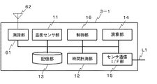
図3には、温度センサ端末3−1の内部構成が示されている。温度センサ端末3−2〜3−nの内部構成も図3に示すものと同様である。図3に示すように、温度センサ端末3は、主として、温度センサ部11、時間計測部12、記憶部13、演算部14、センサ通信I/F(Interface)部15及び制御部16を備える。
FIG. 3 shows the internal configuration of the temperature sensor terminal 3-1. The internal configuration of the temperature sensor terminals 3-2 to 3-n is the same as that shown in FIG. As shown in FIG. 3, the
温度センサ部11には、周囲の温度を示すセンサ値を出力する温度センサが設けられている。時間計測部12は、時間を計測するH/W(Hard Ware)タイマを備えている。時間計測部12は、H/Wタイマを用いて時間を計測する。記憶部13は、温度データを記憶する。演算部14は、制御部16からの指示に従って所定の演算を行う。
The
センサ通信I/F部15は、通信線L1を介して統合管理装置2と接続されたセンサ通信I/F回路を備えている。センサ通信I/F部16は、記憶部13に記憶された温度データを、通信線L1を介して統合管理装置2に送信する。
The sensor communication I /
制御部16は、図示しないMPU(Micro-Processing Unit)、ROM(Read Only Memory)、RAM(Random Access Memory)を備えている。MPUがROMやRAMに格納されたプログラムを実行することにより、制御部16は、各部を統括制御する。
The
図4には、照度センサ端末4−1の内部構成が示されている。照度センサ端末4−2〜4−mの内部構成も、図4に示すものと同様である。図4に示すように、照度センサ端末4−1は、照度センサ部21、時間計測部22、記憶部23、演算部24、センサ通信I/F部25及び制御部26を備える。
FIG. 4 shows an internal configuration of the illuminance sensor terminal 4-1. The internal configuration of the illuminance sensor terminals 4-2 to 4-m is the same as that shown in FIG. As illustrated in FIG. 4, the illuminance sensor terminal 4-1 includes an
照度センサ部21は、照度と相関性のあるセンサ値を検出する照度センサが設けられている。時間計測部22は、時間を計測するH/Wタイマを備えている。時間計測部22は、H/Wタイマを用いて、時間を計測する。記憶部23は、照度データを記憶する。演算部24は、制御部26からの指示に従って所定の演算を行う。
The
センサ通信I/F部25は、通信線L1を介して統合管理装置2と接続されたセンサ通信I/F回路を備えている。センサ通信I/F部25は、記憶部23に格納された照度データを、通信線L1を介して統合管理装置2に送信する。
The sensor communication I /
制御部26は、図示しないMPU、ROM、RAMを備えている。MPUがROMやRAM等に格納されたプログラムを実行することにより、制御部26は、各部を統括制御する。
The
図5(A)には、統合管理装置2の内部構成が示されている。図5(A)に示すように、統合管理装置2は、センサ通信I/F部31、時間計測部32、記憶部33、演算部34、入出力装置35、ユーザI/F部36、制御装置通信I/F部37及び制御部38を備える。
FIG. 5A shows the internal configuration of the
センサ通信I/F部31は、通信線L1を介して各センサ端末(温度センサ端末3−1〜3−n、照度センサ端末4−1〜4−m)と接続されたセンサ通信I/F回路を備えている。センサ通信I/F部31は、各センサ端末(温度センサ端末3−1〜3−n、照度センサ端末4−1〜4−m)から送信された温度データや照度データを入力する。
The sensor communication I /
時間計測部32は、時間を計測するH/Wタイマを備えている。時間計測部32は、H/Wタイマを用いて時間を計測する。
The
記憶部33は、温度データや照度データを記憶する。また、記憶部33は、各センサ端末(温度センサ端末3−1〜3−n、照度センサ端末4−1〜4−m)の位置情報と、各設備機器(空調機8−1〜8−k及び照明器具9−1〜9−h)の位置情報とを記憶する。さらに、記憶部33は、空調機制御装置5−1等、照明制御装置6−1等の制御内容を記憶する。演算部34は、制御部38からの指示に従って所定の演算を行う。
The
入出力装置35は、ユーザI/F部36を介して、制御部38への操作入力情報を入力するとともに、制御部38から出力された所定の情報を表示する。ユーザI/F部36は、ユーザI/F回路を備えており、入出力装置35のインターフェイスとして動作する。
The input /
制御装置通信I/F部37は、通信線L2を介して各制御装置(空調機制御装置5−1〜5−i、照明制御装置6−1〜6−j)と接続された制御装置通信I/F回路を備えている。制御装置通信I/F部37は、空調機制御装置5−1等、照明制御装置6−1等に、生成した制御要求を送信する。
The control device communication I /
制御部38は、図示しないMPU、ROM、RAMを備えている。MPUがROMやRAM等に格納されたプログラムを実行することにより、制御部38は、各部を統括制御する。
The
図5(B)には、制御部38でのプログラム実行により、実現される各種機能が示されている。図5(B)に示すように、制御部38は、故障検出部80と、要求生成部81とを備える。故障検出部80は、記憶部33に記憶された位置情報と、各センサ端末で検出される環境情報としての温度データ、照度データと、空調機制御装置5−1等、照明制御装置6−1等の制御内容に基づいて、空調機8−1〜8−k、照明器具9−1、9−hのいずれかの故障を検出する。要求生成部81は、故障が検出された空調機、照明器具以外の空調機、照明器具に対して、故障検出部80によって故障が検出された空調機、照明器具を補う環境制御を行うための制御要求を生成する。
FIG. 5B shows various functions realized by executing a program in the
図6には、空調機制御装置5−1の内部構成が示されている。空調機制御装置5−2〜5−iの内部構成も図6に示すものと同様である。図6に示すように、空調機制御装置5−1は、制御装置通信I/F部41、記憶部42、演算部43、空調制御部44、入出力装置45、ユーザI/F部46及び制御部47を備える。
FIG. 6 shows an internal configuration of the air conditioner control device 5-1. The internal configuration of the air conditioner control devices 5-2 to 5-i is the same as that shown in FIG. As shown in FIG. 6, the air conditioner control device 5-1 includes a control device communication I /
制御装置通信I/F部41は、通信線L2を介して統合管理装置2と接続された制御装置通信I/F回路を備えている。記憶部42には、統合管理装置2から送信された制御情報等が記憶される。演算部43は、制御部47からの指示に従って、所定の演算を行う。空調制御部44は、通信線L3を介して、1又は複数台の空調機8−1等と接続されている。空調制御部44は、制御部47の制御の下で、演算部43の演算結果等に基づいて、空調機8−1等を制御する空調制御回路を有している。
The control device communication I /
入出力装置45は、ユーザI/F部46を介して、制御部47への操作入力情報を入力するとともに、制御部47から出力された情報を表示する。ユーザI/F部46は、ユーザI/F回路を備えており、入出力装置45のインターフェイスとして動作する。
The input /
制御部47は、図示しないMPU、ROM、RAM、H/Wタイマを備えている。制御部47は、入出力装置45からの操作入力等に従って、MPUがROMやRAM等に格納されたプログラムを実行することにより、各部を統括制御する。
The
図7には、照明制御装置6−1の内部構成が示されている。照明制御装置6−2〜6−jの内部構成も図7に示すものと同様である。図7に示すように、照明制御装置6ー1は、制御装置通信I/F部51、記憶部52、演算部53、照明制御部54、入出力装置55、ユーザI/F部56及び制御部57を備える。
FIG. 7 shows the internal configuration of the illumination control device 6-1. The internal configuration of the illumination control devices 6-2 to 6-j is the same as that shown in FIG. As shown in FIG. 7, the lighting control device 6-1 includes a control device communication I /
制御装置通信I/F部51は、通信線L2を介して統合管理装置2と接続された制御装置通信I/F回路を有している。記憶部52には、統合管理装置2から送信された制御情報等が記憶される。演算部53は、制御部57からの指示に従って、所定の演算を行う。照明制御部54は、電源供給線L4を介して、1又は複数台の照明器具9−1等と接続されている。照明制御部54は、制御部57の制御の下、演算部53の演算結果等に基づいて、照明器具9−1等を制御する照明制御回路を有している。
The control device communication I /
入出力装置55は、ユーザI/F部56を介して、制御部57への操作入力情報を入力するとともに、制御部57から出力された情報を表示する。ユーザI/F部56は、ユーザI/F回路を備えており、入出力装置55のインターフェイスとして動作する。
The input /
制御部57は、図示しないMPU、ROM、RAM、H/Wタイマを備えている。制御部57は、入出力装置55からの操作入力等に従って、MPUがROMやRAM等に格納されたプログラムを実行することにより、各部を統括制御する。
The
次に、各部の動作について説明する。 Next, the operation of each unit will be described.
図8には、温度センサ端末3−1等で実行されるスレッド100が示されている。図8に示すように、まず、温度センサ端末3−1の制御部16は、時間計測部12によって計測される時間を参照して、所定時間が経過したか否かを判定する(ステップS101)。所定時間が経過していなければ(ステップS101;No)、制御部16は、センサ通信I/F部15からプロトコルに基づいて取り出した受信データを解析することにより、センサ情報取得要求を受信したか否かを判定する(ステップS104)。センサ情報取得要求を受信していなければ(ステップS104;No)、制御部16は、ステップS101に戻る。
FIG. 8 shows a
以降、所定時間が経過するか(ステップS101;Yes)、センサ情報取得要求を受信するまで(ステップS104;Yes)、制御部16は、ステップS101→S104を繰り返す。
Thereafter, the
所定時間が経過すると(ステップS101;Yes)、制御部16は、温度センサ部11から温度センサ情報を取得する(ステップS102)。制御部16は、温度センサ情報を記憶部13に記憶する(ステップS103)。
When the predetermined time has elapsed (step S101; Yes), the
一方、センサ情報取得要求を受信した場合(ステップS104;Yes)、制御部16は、演算部14を用いて、記憶部13に記憶された温度センサ情報を送信データに加工し、センサ通信I/F部16を介して統合管理装置2に送信する(ステップS105)。その後、制御部16は、ステップS101に戻る。
On the other hand, when the sensor information acquisition request is received (step S104; Yes), the
図9には、照度センサ端末4−1等で実行されるスレッド200の流れが示されている。図9に示すように、まず、照度センサ端末4−1の制御部26は、時間計測部22によって計測される時間を参照して、所定時間が経過したか否かを判定する(ステップS201)。所定時間が経過していなければ(ステップS201;No)、制御部26は、センサ通信I/F部25からプロトコルに基づいて取り出した受信データを解析することにより、センサ情報取得要求を受信したか否かを判定する(ステップS204)。センサ情報取得要求を受信していなければ(ステップS204;No)、制御部26は、ステップS201に戻る。
FIG. 9 shows the flow of the
以降、所定時間が経過するか(ステップS201;Yes)、センサ情報取得要求を受信するまで(ステップS204;Yes)、制御部26は、ステップS201→S204を繰り返す。
Thereafter, the
所定時間が経過すると(ステップS201;Yes)、制御部26は、照度センサ部21から照度センサ情報を取得する(ステップS202)。制御部26は、照度センサ情報を記憶部24に記憶する(ステップS203)。
When the predetermined time has elapsed (step S201; Yes), the
一方、センサ情報取得要求を受信した場合(ステップS204;Yes)、制御部26は、演算部24を用いて、記憶部24に記憶された温度センサ情報を送信データに加工し、センサ通信I/F部26を介して統合管理装置2に送信する(ステップS205)。その後、制御部26は、ステップS201に戻る。
On the other hand, when the sensor information acquisition request is received (step S204; Yes), the
続いて、統合管理装置2の動作について説明する。図10(A)には、統合管理装置2によって実行されるスレッド300が示され、図10(B)には、統合管理装置2によって実行されるスレッド350が示されている。
Next, the operation of the
図10(A)を参照して、スレッド300について説明する。図10(A)に示すように、まず、統合管理装置2の制御部38は、時間計測部35によって計測される時間を参照して、所定時間経過するまで待つ(ステップS301;No)。所定時間が経過した場合(ステップS301;Yes)、制御部38は、温度センサ端末3−1等又は照度センサ端末4−1等の端末識別子の1つを宛先として、センサ通信I/F部31を介してセンサ情報取得要求を送信する(ステップS302)。宛先の端末識別子は、このステップS302が実行される度に、対象となっているセンサ端末(温度センサ端末3−1等又は照度センサ端末4−1等)のうち、未送信のセンサ端末の中から順次選択される。
The
続いて、制御部38は、対象のセンサ端末からセンサ情報を受信したか否かを判定する(ステップS303)。受信していなければ、制御部38は、タイムアウトしたか否かを判定する(ステップS304)。タイムアウトしていなければ(ステップS304;No)、制御部38は、ステップS303に戻る。以降、センサ情報を受信するか(ステップS303;Yes)、タイムアウトするまで(ステップS304;Yes)、ステップS303→S304が繰り返される。
Subsequently, the
センサ情報を受信すると(ステップS303;Yes)、制御部38は、記憶部33に受信したセンサ情報を記憶する(ステップS305)。センサ情報は時系列データとして順次記憶される。
When sensor information is received (step S303; Yes), the
センサ情報を記憶した後、又はタイムアウトした場合(ステップS304;Yes)、制御部38は、対象となる全てのセンサ端末にセンサ情報取得要求を送信したか否かを判定する(ステップS306)。全てのセンサ端末へのセンサ情報取得要求の送信がまだ完了していなければ(ステップS306;No)、制御部38はステップS302に戻る。
After storing the sensor information or when a time-out occurs (step S304; Yes), the
以降、全てのセンサ端末にセンサ情報取得要求が送信されるまで(ステップS306;Yes)、センサ情報取得要求の送信(ステップS302)→センサ情報の受信待ち(ステップS303→S304)→センサ情報の記憶(ステップS305)等が繰り返される。 Thereafter, until a sensor information acquisition request is transmitted to all sensor terminals (step S306; Yes), transmission of the sensor information acquisition request (step S302) → waiting reception of sensor information (step S303 → S304) → storage of sensor information (Step S305) and the like are repeated.
全てのセンサ端末にセンサ情報取得要求が送信されると(ステップS306;Yes)、制御部38(故障検出部80)は、記憶部33に記憶された各センサ端末の位置情報を考慮して、温度センサ情報、照明センサ情報と、空調機制御装置5−1等、照明制御装置6−1等の現在の制御内容等との違いに基づいて、設備機器(空調機8−1等、照明器具9−1等)の故障の検出処理を行う(ステップS307)。
When the sensor information acquisition request is transmitted to all the sensor terminals (step S306; Yes), the control unit 38 (failure detection unit 80) considers the position information of each sensor terminal stored in the
続いて、制御部38(要求生成部81)は、記憶部33に記憶された各センサ端末のセンサ情報および故障の検出結果に基づいて、空調機制御装置5−1等、照明制御装置6−1等へ送信する機器制御要求を生成する(ステップS308)。より具体的には、制御部38は、記憶部33に記憶された位置情報に基づいて、故障が検出された設備機器(空調機8−1等、照明器具9−1等)に近接する設備機器を検出する。そして、制御部38は、近接する設備機器に対して、故障が検出された設備機器を補う環境制御を行わせるための機器制御要求を生成する。
Subsequently, the control unit 38 (request generation unit 81), based on the sensor information of each sensor terminal stored in the
続いて、制御部38は、対象の空調機制御装置5−1等又は照明制御装置6−1等の装置識別子を宛先として、制御装置通信I/F部37に、機器制御要求を送信させる(ステップS309)。対象の空調機制御装置5−1等又は照明制御装置6−1等が複数ある場合はにそれらすべての装置に対して機器制御要求が順次送信される。続いて、制御部38は、空調機制御装置5−1等、照明制御装置6−1等の制御内容を記憶部33に記憶する(ステップS310)。その後、制御部38は、ステップS301に戻る。
Subsequently, the
続いて、図10(B)を参照して、統合管理装置2によって実行されるスレッド350について説明する。
Next, the
まず、制御部38は、制御装置通信I/F部37を介して、空調機制御装置5−1等又は照明制御装置6−1等から制御変更通知を受信するまで待つ(ステップS351;No)。制御変更通知を受信すると(ステップS351;Yes)、制御部38は、受信した制御変更通知の内容(現在の設備機器の制御内容)を、統合管理装置2の記憶部33に記憶する(ステップS352)。その後、制御部38は、ステップS351に戻る。
First, the
続いて、故障の検出方法と機器制御要求内容の決定方法について、図2を参照して説明する。 Next, a failure detection method and a device control request content determination method will be described with reference to FIG.
例えば、空調機8−1が故障したとする。この場合、空調機制御装置5−1が空調機8−1を制御しているにも関わらず、温度センサ端末3−1によってセンシングされる温度が、統合管理装置2の記憶部33に記憶された時系列の温度データと異なるようになる。統合管理装置2の制御部38は、例えば、それらの差が所定値以上となった場合に、空調機8−1が故障したと判定する。ここで、故障判定は、空調機制御装置5−1による制御内容、すなわち、統合管理装置2の記憶部33に記憶された現在の設定温度、風向きなどの設定、空調機のオン/オフなどを加味して行われる。
For example, assume that the air conditioner 8-1 has failed. In this case, although the air conditioner control device 5-1 controls the air conditioner 8-1, the temperature sensed by the temperature sensor terminal 3-1 is stored in the
故障したと判定された場合、制御部38は、統合管理装置2のユーザI/F部37を介して入出力装置35に故障箇所等の故障が検出された設備機器に関する情報を表示させる。また、制御部38は、空調機8−1(故障機器)周辺のエリアの空調も行えるように、空調機8−1近傍の空調機8−2の設定温度、風向きなどを変更するような機器制御要求を生成する。
When it is determined that a failure has occurred, the
また、例えば、照明器具9−2が故障したとする。この場合、照度センサ端末4−2が取得する照度が、統合管理装置2の記憶部33に記憶された時系列の照度データと異なるようになる。統合管理装置2の制御部38は、例えば、それらの差が所定値以上となった場合に、照明器具9−2が故障したと判定する。ここで、故障判定は、照明制御装置6−1の制御内容、すなわち統合管理装置2の記憶部34に記憶された現在の明るさ、向きなどの設定、照明器具のオン/オフなどを加味して行われる。
Further, for example, it is assumed that the lighting fixture 9-2 has failed. In this case, the illuminance acquired by the illuminance sensor terminal 4-2 is different from the time-series illuminance data stored in the
故障したと判定された場合、制御部38は、統合管理装置2のユーザI/F部37を介して入出力装置35に故障箇所を表示させる。また、制御部38は、照明器具9−2周辺のエリアの照明の制御も行えるように、照明器具9−1、9−3の明るさ、向きなどを変更するような機器制御要求を生成する。
When it is determined that a failure has occurred, the
なお、空調機8−1等、照明器具9−1等の制御は図5(A)の統合管理装置2の入出力装置35によって人為的に行うこともできる。その場合は、ユーザI/F部36を介して入力され、制御装置通信I/F部37を介して空調機8−1等、照明器具9−1等の制御が行われる。制御内容(温度設定やオン/オフなど)は、統合管理装置2の記憶部33に記憶され、故障判定の際などに参照される。
Note that the control of the air conditioner 8-1 and the like, the lighting fixture 9-1, and the like can be artificially performed by the input /
続いて、空調機制御装置5−1等の動作について説明する。図11(A)には、空調機制御装置5−1によって実行されるスレッド400が示されている。また、図11(B)には、空調機制御装置5−1によって実行されるスレッド450が示されている。
Then, operation | movement of the air-conditioner control apparatus 5-1 grade | etc., Is demonstrated. FIG. 11A shows a
まず、図11(A)を参照して、スレッド400について説明する。まず、制御部47は、制御装置通信I/F部41を介して統合管理装置2から機器制御要求を受信するまで待つ(ステップS401:No)。機器制御要求を受信すると(ステップS401;Yes)、制御部47は、空調制御部44を介して対象の空調機に制御命令を送信する(ステップS402)。ここで、制御命令とは、空調機に温度、風向き、風速などの制御を行わせるための命令である。対象の空調機が複数ある場合は、そのすべてに対して制御命令が順次送信される。その後、制御部47は、ステップS401に戻る。
First, the
続いて、図11(B)を参照して、スレッド450について説明する。まず、制御部47は、ユーザI/F部46を介して入出力装置45から空調制御の操作入力を入力するまで待つ(ステップS451;No)。ここで、空調制御の操作入力とは、空調機の温度、風向き、風速などの制御を行うために管理者によって入力される人為的な操作入力のことである。
Next, the
空調制御の操作入力を入力すると(ステップS451;Yes)、制御部47は、空調制御部44を介して対象の空調機に制御命令を送信する(ステップS452)。対象の空調機が複数ある場合は、そのすべてに対して制御命令が順次送信される。さらに、制御部47は、統合管理装置2に対して、空調制御の変更通知を送信する(ステップS453)。その後、制御部47は、ステップS451に戻る。
When an operation input for air conditioning control is input (step S451; Yes), the
続いて、照明制御装置6−1等の動作について説明する。図12(A)には、照明制御装置6−1によって実行されるスレッド500が示され、図12(B)には、照明制御装置6−1によって実行されるスレッド550が示されている。
Then, operation | movement of the illumination control apparatus 6-1 grade | etc., Is demonstrated. 12A shows the
まず、図12(A)を参照して、スレッド500について説明する。図12(A)に示すように、まず、制御部57は、制御装置通信I/F部51を介して統合管理装置2から機器制御要求を受信するまで待つ(ステップS501;No)。
First, the
機器制御要求を受信すると(ステップS501;Yes)、制御部57は、照明制御部54を介して対象の照明器具に対して照明制御を行う(ステップS502)。ここで、照明制御とは、照明の明るさ、色、向きなどの制御を意味する。対象の照明器具が複数ある場合は、それらすべての装置が順次制御される。その後、制御部57は、ステップS501に戻る。
When the device control request is received (step S501; Yes), the
続いて、図12(B)を参照して、スレッド550について説明する。まず、制御部57は、ユーザI/F部56を介して入出力装置55から照明制御の操作入力があるまで待つ(ステップS551;No)。照明制御の操作入力があると(ステップS551;Yes)、制御部57は、照明制御部54を介して対象の照明器具の照明制御を行う(ステップS552)。対象の照明器具が複数ある場合は、そのすべてに対して制御が順次行われる。続いて、制御部57は、統合管理装置2に対して、照明制御の変更通知を送信する(ステップS553)。その後、制御部57は、ステップS551に戻る。ここで、照明制御の操作入力とは、照明の明るさ、色、向きなどの制御を行うために管理者によって入力される人為的な操作入力のことである。
Next, the
図13には、統合管理装置2と空調機部8との間で送受信される情報の流れの一例が示されている。図13に示すように、まず、統合管理装置2は、センサ情報取得要求C1を温度センサ部3(温度センサ端末3−1等)に送信する。それに対して温度センサ部3の温度センサ端末3−1等は、センサ情報C2を統合管理装置2に送信する。センサ情報取得要求C1とセンサ情報C2との送受信は、対象の温度センサ端末3−1等の数だけ繰り返される。
FIG. 13 shows an example of a flow of information transmitted and received between the
その後、統合管理装置2は、機器制御要求C3を空調機部5の対象の1又は複数台の空調機制御装置5−1等に順次送信する。それを受けて、空調機部5の空調機制御装置5−1等は、空調制御命令C4を、対象の1又は複数台の空調機部8の空調機8−1等に順次送信する。
Thereafter, the
図14には、統合管理装置2と照明部9との間で送受信される情報の流れの一例が示されている。図14に示すように、統合管理装置2は、センサ情報取得要求C11を照度センサ部4の照度センサ端末4−1等に送信する。それに対して照度センサ部4の照度センサ端末4−1等は、センサ情報C12を統合管理装置2に送信する。センサ情報取得要求C11とセンサ情報C12との送受信は、対象の照度センサ端末4−1等の数だけ繰り返される。
FIG. 14 shows an example of a flow of information transmitted / received between the
その後、統合管理装置2は、機器制御要求C13を、照明制御部6において、対象となる1又は複数台の照明制御装置6−1等に順次送信する。それを受けて、照明制御部6の照明制御装置6−1等は、照明制御命令C14を、照明部9において、対象となる1又は複数台の照明器具9−1等に順次送信する。
After that, the
以上詳細に説明したように、この実施の形態の設備管理システム1によれば、空調機・照明器具の故障が発生した場合に、他の空調機・照明器具によって故障した空調機・照明器具が補われる環境制御を行うことができる。これにより、在室者の快適性の低下を防止することができる。
As described above in detail, according to the
なお、この実施の形態では、照明制御装置6−1等と統合管理装置2とを別々の構成要素として分けているが、機能をまとめて1つの装置としてもよい。
In this embodiment, the lighting control device 6-1 and the like and the
また、この実施の形態では、空調機制御装置5−1等と統合管理装置2とを別々の構成要素として分けているが、機能をまとめて1つの装置としてもよい。
Further, in this embodiment, the air conditioner control device 5-1 and the like and the
また、この実施の形態では、温度センサ端末3−1〜3−n及び照度センサ端末4−1〜4−mは、所定時間ごとにセンサ値を検出し、記憶している。しかしながら、これには限られず、センサ情報取得要求を受信したときにセンサ値を取得するようにしてもよい。 Moreover, in this embodiment, the temperature sensor terminals 3-1 to 3-n and the illuminance sensor terminals 4-1 to 4-m detect and store sensor values every predetermined time. However, the present invention is not limited to this, and the sensor value may be acquired when a sensor information acquisition request is received.
また、この実施の形態では、各センサ端末(温度センサ端末3−1〜3−n、照度センサ端末4−1〜4−m)と、各設備機器(空調機8−1〜8−k、照明器具9−1〜9−h)を分けて設置したが、各設備機器に各センサ端末を組み込んでもよい。 In this embodiment, each sensor terminal (temperature sensor terminals 3-1 to 3-n, illuminance sensor terminals 4-1 to 4-m) and each equipment (air conditioners 8-1 to 8-k, Although the lighting fixtures 9-1 to 9-h) are separately installed, each sensor terminal may be incorporated in each equipment.
また、この実施の形態では、各センサ端末(温度センサ端末3−1〜3−n、照度センサ端末4−1〜4−m)で温度と照度を検出している。しかしながら、湿度を検知して、湿度によって空調制御を行うようにしてもよい。 In this embodiment, temperature and illuminance are detected by each sensor terminal (temperature sensor terminals 3-1 to 3-n, illuminance sensor terminals 4-1 to 4-m). However, humidity may be detected and air conditioning control may be performed based on the humidity.
また、この実施の形態では、温度センサの代わりに赤外線センサを用いるようにしてもよい。この場合には、赤外線センサから得られた熱画像に基づいて、故障が検知されるようになる。 In this embodiment, an infrared sensor may be used instead of the temperature sensor. In this case, a failure is detected based on the thermal image obtained from the infrared sensor.
また、この実施の形態では、通信線L1〜L3を有線としているが、無線としてもよい。 In this embodiment, the communication lines L1 to L3 are wired, but may be wireless.
また、この実施の形態では、照明器具9−1〜9−hを可動式として、故障箇所に照明を向けることで補完制御を行うようにしてもよい。 Further, in this embodiment, the lighting fixtures 9-1 to 9-h may be movable, and complementary control may be performed by directing illumination to the failure location.
また、この実施の形態では、照明器具9−1〜9−hはLED(Light Emitting Diode)を用いてもよく、指向性を利用して照明の向きを変えて故障箇所の補完制御を行うようにしてもよい。 Further, in this embodiment, the lighting fixtures 9-1 to 9-h may use LEDs (Light Emitting Diodes) and change the direction of illumination by using directivity to perform complementary control of a failure location. It may be.
また、この実施の形態では、照明器具9−1〜9−hの近傍に反射板を設け、反射板の向きを変えることで故障箇所の補完制御を行ってもよい。 Moreover, in this embodiment, a reflecting plate may be provided in the vicinity of the lighting fixtures 9-1 to 9-h, and the complementary control of the failure location may be performed by changing the direction of the reflecting plate.
実施の形態2.
次に、この発明の実施の形態2について説明する。
Next, a second embodiment of the present invention will be described.
この実施の形態に係る設備管理システム1の構成は、図1に示す上記実施の形態1の設備管理システム1の構成と同様である。この実施の形態では、上記実施の形態1と同じ構成要素には同一の符号を付与し、説明を省略する。
The configuration of the
この実施の形態では、上記実施の形態1に係る温度センサ端末3−1〜3−nと照度センサ端末4−1〜4−mとに、端末間の距離を測定する機能が付加されている。 In this embodiment, a function of measuring the distance between the terminals is added to the temperature sensor terminals 3-1 to 3-n and the illuminance sensor terminals 4-1 to 4-m according to the first embodiment. .
この実施の形態の各センサ端末と各設備機器の制御装置を居室空間AR1に設置した際の配置は、図2に示す上記実施の形態1の配置例と同様である。 The arrangement when the sensor terminals and the control devices for the respective equipments of this embodiment are installed in the room space AR1 is the same as the arrangement example of the first embodiment shown in FIG.
また、この実施の形態では、各センサ端末と各設備機器との間には1対1の対応関係があるものとする。設備機器と対になるセンサ端末は、設備機器の中に組み込まれているか、設備機器の近くに設置されている。統合管理装置2には、各センサ端末と各設備機器の識別子の対応関係が予め登録されている。なお、少なくとも3つのセンサ端末には、位置情報が予め設定されているものとする。
In this embodiment, it is assumed that there is a one-to-one correspondence between each sensor terminal and each facility device. The sensor terminal paired with the equipment is incorporated in the equipment or is installed near the equipment. In the
図15には、この実施の形態に係る温度センサ端末3の内部構成が示されている。図15に示すように、温度センサ端末3−1は、測距部61とアンテナ62とをさらに備える点が上記実施の形態1と異なる。測距部61は、測距回路を有している。
FIG. 15 shows an internal configuration of the
図16には、この実施の形態に係る照度センサ端末4−1の内部構成が示されている。図16に示すように、照度センサ端末4−1は、測距部71とアンテナ72とをさらに備える点が上記実施の形態1と異なる。測距部71は、測距回路を有している。
FIG. 16 shows the internal configuration of the illuminance sensor terminal 4-1 according to this embodiment. As illustrated in FIG. 16, the illuminance sensor terminal 4-1 is different from the first embodiment in that the illuminance sensor terminal 4-1 further includes a distance measuring unit 71 and an
この実施の形態に係る統合管理装置2、空調機制御装置5−1等及び照明制御装置6−1等の内部構成は、図5(A)、図5(B)、図6、図7に示す内部構成と同様である。
The internal configuration of the
この実施の形態の統合管理装置2の基本的な動作は、図10に示す上記実施の形態1の統合管理装置2の動作と同様である。ただし、この実施の形態では、統合管理装置2は、図10のフローチャートに示す動作に先だって、図17のフローチャートに示すスレッド600を統合管理装置2が行う必要がある。
The basic operation of the
図17に示すように、制御部38は、温度センサ端末3−1等又は照度センサ端末4−1等の端末識別子の1つを宛先として、センサ通信I/F部31を介して測距開始要求を送信する(ステップS601)。宛先の端末識別子は、このステップを実行する度に、未送信の対象のセンサ端末の中から順次選択される。
As shown in FIG. 17, the
続いて、制御部38は、対象のセンサ端末から測距結果を受信したか否かを判定する(ステップS602)。受信していない場合(ステップS602;No)、制御部38は、タイムアウトしたか否かを判定する(ステップS603)。タイムアウトしていなければ(ステップS603;No)、制御部38は、ステップS602に戻る。以降、測距結果を受信するか(ステップS602;Yes)、タイムアウトするまで(ステップS603;Yes)、ステップS602→S603が繰り返される。
Subsequently, the
測距結果を受信すると(ステップS602;Yes)、制御部38は、記憶部33に受信した測距結果を記憶する(ステップS604)。
When the distance measurement result is received (step S602; Yes), the
測距結果を記憶した後、又はタイムアウトした場合(ステップS603;Yes)、制御部38は、対象となる全てのセンサ端末に測距開始要求を送信したか否かを判定する(ステップS605)。全てのセンサ端末への測距開始要求の送信がまだ完了していなければ(ステップS605;No)、制御部38はステップS601に戻る。
After storing the distance measurement result or when a time-out occurs (step S603; Yes), the
以降、全てのセンサ端末に測距結果取得要求が送信されるまで(ステップS605;No)、測距結果取得要求の送信(ステップS601)→測距結果の受信待ち(ステップS602→S603)→測距結果の記憶(ステップS604)等が繰り返される。 Thereafter, until distance measurement result acquisition requests are transmitted to all sensor terminals (step S605; No), transmission of distance measurement result acquisition requests (step S601) → waiting reception of distance measurement results (step S602 → S603) → measurement The distance result storage (step S604) and the like are repeated.
全てのセンサ端末に測距結果取得要求が送信されると(ステップS605;Yes)、制御部38は、記憶部33に記憶された各センサ端末の測距結果に基づいて、各センサ端末の位置を推定する(ステップS606)。続いて、制御部38は、記憶部33に推定した各センサ端末の位置を記憶する(ステップS607)。その後、制御部38は、スレッド600を終了する。
When the ranging result acquisition request is transmitted to all the sensor terminals (step S605; Yes), the
センサ端末の位置を測定する方法について、図18を参照して説明する。 A method for measuring the position of the sensor terminal will be described with reference to FIG.
温度センサ端末3−1〜3〜4が居室空間に設置されているものとする。温度センサ端末3−2〜3−4の位置情報は、統合管理装置2の記憶部33に予め設定されている。ここで、統合管理装置2が温度センサ端末3−1に測距開始要求を送信したとする。すると、温度センサ端末3−1は、温度センサ端末3−2〜3−4に測距要求C20―1〜C20−3をブロードキャストで無線で送信する。測距要求C20―1〜C20−3を受信した温度センサ端末3−2〜3−4は、測距応答C21−1〜C21−3を温度センサ端末3−1に無線で返信する。温度センサ端末3−1は一定時間、測距応答を受け付ける。温度センサ端末3−1は、測距要求C20―1〜C20−3を送信してから測距応答C21−1〜C21−3を受信するまでの時間に基づいて、各温度センサ端末3−2〜3−4までの距離D1〜D3を推定する。
It is assumed that the temperature sensor terminals 3-1 to 3-4 are installed in the living room space. The position information of the temperature sensor terminals 3-2 to 3-4 is set in advance in the
なお、測距応答C21−1〜C21−3には、返信した温度センサ端末3−2〜3−4の識別子が含まれる。温度センサ端末3−1は、温度センサ端末3−2〜3−4の識別子と距離D1〜D3とを対応付けて測距結果として統合管理装置2に送信する。統合管理装置2は、温度センサ端末3−2〜3−4の位置をそれぞれ円の中心点とし、距離D1〜D3をそれぞれ円の半径として、それらの円の交点を温度センサ端末3−1の位置として算出する。この実施の形態の測距で用いられる無線方式としては、例えばUWB(Ultra Wide Band)を採用することができる。
The distance measurement responses C21-1 to C21-3 include the identifiers of the returned temperature sensor terminals 3-2 to 3-4. The temperature sensor terminal 3-1 associates the identifiers of the temperature sensor terminals 3-2 to 3-4 with the distances D1 to D3, and transmits them to the
この実施の形態に係る温度センサ端末3−1及び照度センサ端末4−1の基本的な動作は、図8、図9に示す実施の形態1の温度センサ端末3−1等及び照度センサ端末4−1等の動作と同様である。
The basic operations of the temperature sensor terminal 3-1 and the illuminance sensor terminal 4-1 according to this embodiment are the temperature sensor terminal 3-1 and the
ただし、この実施の形態では、図8、図9に示す動作に先立って、図19に示す温度センサ端末3−1等のスレッド700が実行される。図19に示すように、温度センサ端末3−1等を例として使用しているが、照度センサ端末4−1等で同様の動作が行われてもよい。
However, in this embodiment, prior to the operations shown in FIGS. 8 and 9, the
制御部16は、統合管理装置2から測距開始要求を受信するまで待つ(ステップS701;No)。測距開始要求を受信すると(ステップS701;Yes)、制御部16は、他の温度センサ端末に測距要求をブロードキャストで送信する(ステップS702)。続いて、制御部16は、測距応答を受け付ける所定の時間が経過するまで待つ(ステップS703;No)。所定時間が経過すると(ステップS703;Yes)、制御部16は、測距要求を送信してから測距応答を受信するまでの時間から、各センサ端末の距離を推定する(ステップS704)。続いて、制御部16は、統合管理装置2に測距結果を送信する(ステップS705)。その後、制御部16は、スレッドを終了する。
The
以上詳細に説明したように、この実施の形態の設備管理システム1によれば、空調機・照明器具の故障検知及びそれらの機器の自動補完ができることに加え、各センサ端末への設置位置の入力作業を省略することができる。これにより、在室者の快適性を損なわない空調・照明制御が可能になるうえ、各センサ端末の設置作業を容易なものとすることができる。
As described in detail above, according to the
なお、上記実施の形態において、実行されるプログラムは、フレキシブルディスク、CD−ROM(Compact Disc Read-Only Memory)、DVD(Digital Versatile Disc)、MO(Magneto-Optical Disc)等のコンピュータ読み取り可能な記録媒体に格納して配布し、そのプログラムをインストールすることにより、上述のスレッドを実行するシステムを構成することとしてもよい。 In the above embodiment, the program to be executed is a computer-readable recording medium such as a flexible disk, a CD-ROM (Compact Disc Read-Only Memory), a DVD (Digital Versatile Disc), and an MO (Magneto-Optical Disc). A system that executes the above-described thread may be configured by storing and distributing the program in a medium and installing the program.
また、プログラムをインターネット等の通信ネットワーク上の所定のサーバ装置が有するディスク装置等に格納しておき、例えば、搬送波に重畳させて、ダウンロード等するようにしてもよい。 Further, the program may be stored in a disk device or the like of a predetermined server device on a communication network such as the Internet, and may be downloaded, for example, superimposed on a carrier wave.
また、上述の機能を、OS(Operating System)が分担して実現する場合又はOSとアプリケーションとの協働により実現する場合等には、OS以外の部分のみを媒体に格納して配布してもよく、また、ダウンロード等してもよい。 In addition, when the above functions are realized by sharing an OS (Operating System), or when the functions are realized by cooperation between the OS and an application, only the part other than the OS may be stored in a medium and distributed. You may also download it.
この発明は、この発明の広義の精神と範囲を逸脱することなく、様々な実施の形態及び変形が可能とされるものである。また、上述した実施の形態は、この発明を説明するためのものであり、この発明の範囲を限定するものではない。すなわち、この発明の範囲、実施の形態ではなく、特許請求の範囲によって示される。そして、特許請求の範囲内及びそれと同等の発明の意義の範囲内で施される様々な変形が、この発明の範囲内とみなされる。 Various embodiments and modifications can be made to the present invention without departing from the broad spirit and scope of the present invention. The above-described embodiments are for explaining the present invention and do not limit the scope of the present invention. That is, the scope of the present invention is not indicated by the embodiments but by the scope of the claims. Various modifications within the scope of the claims and within the scope of the equivalent invention are considered to be within the scope of the present invention.
この発明の活用例として、オフィス等の居室空間の環境制御に好適である。 As an application example of the present invention, it is suitable for environmental control of a room space such as an office.
1 設備管理システム
2 統合管理装置
3 温度センサ部
3−1〜3−n 温度センサ端末
4 照度センサ部
4−1〜4−m 照度センサ端末
5 空調制御部
5−1〜5−i 空調機制御装置
6 照明制御部
6−1〜6−j 照明制御装置
8 空調機部
8−1〜8−k 空調機
9 照明部
9−1〜9−h 照明器具
11 温度センサ部
12 時間計測部
13 記憶部
14 演算部
15 センサ通信I/F部
16 制御部
21 照度センサ部
22 時間計測部
23 記憶部
24 演算部
25 センサ通信I/F部
26 制御部
31 センサ通信I/F部
32 時間計測部
33 記憶部
34 演算部
35 入出力装置
36 ユーザI/F部
37 制御装置通信I/F部
38 制御部
41 制御装置通信I/F部
42 記憶部
43 演算部
44 空調制御部
45 入出力装置
46 ユーザI/F部
47 制御部
51 制御装置通信I/F部
52 記憶部
53 演算部
54 照明制御部
55 入出力装置
56 ユーザI/F部
57 制御部
61 測距部
62 アンテナ
71 測距部
72 アンテナ
80 故障検出部
81 要求生成部
100 スレッド
200 スレッド
300、350 スレッド
400、450 スレッド
500、550 スレッド
600、700 スレッド
C1 センサ情報取得要求
C2 センサ情報
C3 機器制御要求
C4 空調制御命令
C11 センサ情報取得要求
C12 センサ情報
C13 機器制御要求
C14 照明制御命令
C20−1、C20−2、C20−3 測距要求
C21−1、C21−2、C21−3 測距応答
D1、D2、D3 距離
L1、L2、L3 通信線
L4 電源供給線
DESCRIPTION OF SYMBOLS 1 Facility management system 2 Integrated management apparatus 3 Temperature sensor part 3-1 to 3-n Temperature sensor terminal 4 Illuminance sensor part 4-1 to 4-m Illuminance sensor terminal 5 Air conditioning control part 5-1 to 5-i Air conditioner control Device 6 Lighting control unit 6-1 to 6-j Lighting control device 8 Air conditioner unit 8-1 to 8-k Air conditioner 9 Lighting unit 9-1 to 9-h Lighting fixture 11 Temperature sensor unit 12 Time measuring unit 13 Storage Unit 14 Calculation Unit 15 Sensor Communication I / F Unit 16 Control Unit 21 Illuminance Sensor Unit 22 Time Measurement Unit 23 Storage Unit 24 Calculation Unit 25 Sensor Communication I / F Unit 26 Control Unit 31 Sensor Communication I / F Unit 32 Time Measurement Unit 33 Storage unit 34 Calculation unit 35 Input / output device 36 User I / F unit 37 Control device communication I / F unit 38 Control unit 41 Control device communication I / F unit 42 Storage unit 43 Calculation unit 44 Air conditioning control unit 45 Input / output device 4 User I / F unit 47 Control unit 51 Control device communication I / F unit 52 Storage unit 53 Calculation unit 54 Illumination control unit 55 Input / output device 56 User I / F unit 57 Control unit 61 Distance measurement unit 62 Antenna 71 Distance measurement unit 72 Antenna 80 Failure detection unit 81 Request generation unit 100 thread 200 thread 300, 350 thread 400, 450 thread 500, 550 thread 600, 700 thread C1 sensor information acquisition request C2 sensor information C3 device control request C4 air conditioning control command C11 sensor information acquisition request C12 Sensor information C13 Device control request C14 Lighting control command C20-1, C20-2, C20-3 Distance request C21-1, C21-2, C21-3 Distance response D1, D2, D3 Distance L1, L2, L3 Communication line L4 Power supply line
Claims (10)
前記記憶部に記憶された前記各設備機器の位置情報及び前記各検出装置の位置情報と、前記各設備機器を用いた環境制御を行う制御装置の制御内容と、前記各検出装置で検出される環境情報とに基づいて、前記各設備機器の故障を検出する故障検出部と、
故障が検出された設備機器以外の設備機器に対して、前記故障検出部によって故障が検出された設備機器を補う環境制御を行うための制御要求を生成する要求生成部と、
前記制御装置に、生成した制御要求を送信する送受信部と、
を備える管理装置。 A storage unit for storing position information of a plurality of equipment devices respectively installed in different places of a predetermined living room space, and position information of a plurality of detection devices respectively installed in different places of the living room space and detecting environmental information; ,
The position information of each facility device and the position information of each detection device stored in the storage unit, the control content of a control device that performs environmental control using each facility device, and detected by each detection device A failure detection unit that detects a failure of each facility device based on environmental information;
A request generation unit that generates a control request for performing environmental control to supplement the facility device in which the failure is detected by the failure detection unit, for facility devices other than the facility device in which the failure is detected;
A transmission / reception unit for transmitting the generated control request to the control device;
A management device comprising:
前記制御装置の制御内容が同じであるにもかかわらず、当該制御装置によって制御される設備機器に最も近い検出装置によって検出される環境情報が所定レベル以上変化した場合に、当該設備機器が故障したものと判定する、
請求項1に記載の管理装置。 The failure detection unit
Despite the fact that the control contents of the control device are the same, the equipment has failed when the environmental information detected by the detection device closest to the equipment controlled by the control device has changed more than a predetermined level. Judge that
The management apparatus according to claim 1.
前記記憶部に記憶された前記各設備機器の位置情報及び前記各検出装置の位置情報に基づいて、故障が検出された設備機器に近接する設備機器を検出し、
近接する設備機器に対して、故障が検出された設備機器を補う環境制御を行わせるための制御要求を生成する、
請求項1又は2に記載の管理装置。 The request generation unit
Based on the location information of each facility device stored in the storage unit and the location information of each detection device, detects the facility device adjacent to the facility device in which a failure is detected,
Generate a control request for performing environmental control to make up for the equipment in which a failure has been detected for neighboring equipment.
The management device according to claim 1 or 2.
請求項1乃至3のいずれか一項に記載の管理装置。 A notification unit for notifying the administrator of information related to the equipment in which the failure is detected;
The management apparatus as described in any one of Claims 1 thru | or 3.
前記各設備機器を用いた環境制御を行う制御装置と、
前記居室空間の異なる場所にそれぞれ設置され環境情報を検出する複数の検出装置と、
請求項1乃至4のいずれか一項に記載の管理装置と、
を備える管理システム。 A plurality of equipment installed in different places of a predetermined living room,
A control device that performs environmental control using each facility device;
A plurality of detection devices installed in different places of the living room space to detect environmental information;
The management device according to any one of claims 1 to 4,
A management system comprising:
前記位置が既知である少なくとも3つの他の検出装置との間で無線信号を送信してから受信するまでの間を計測することにより、前記少なくとも3つの他の検出装置との間の距離を計測し、
計測した距離と、前記少なくとも3つの他の検出装置の識別番号とを対応付けた情報を、前記管理装置に送信し、
前記管理装置は、
受信した情報に基づいて、当該検出装置の位置情報を算出する、
請求項5に記載の管理システム。 Each of the detection devices is
The distance between the at least three other detection devices is measured by measuring the time between transmission and reception of a radio signal with at least three other detection devices whose positions are known. And
Information that associates the measured distance with the identification numbers of the at least three other detection devices is transmitted to the management device,
The management device
Based on the received information, the position information of the detection device is calculated.
The management system according to claim 5.
温度センサ、熱画像を得る赤外線センサ、照度センサ及び湿度センサのいずれかである、
請求項5又は6に記載の管理システム。 Each of the detection devices is
One of a temperature sensor, an infrared sensor for obtaining a thermal image, an illuminance sensor, and a humidity sensor.
The management system according to claim 5 or 6.
空調機及び照明器具のいずれかである、
請求項5乃至7のいずれか一項に記載の管理システム。 Each facility device is
Either an air conditioner or a lighting fixture,
The management system according to any one of claims 5 to 7.
前記記憶工程において記憶された前記各設備機器の位置情報及び前記各検出装置の位置情報と、前記各設備機器を用いた環境制御を行う制御装置の制御内容と、前記各検出装置で検出される環境情報とに基づいて、前記各設備機器の故障を検出する故障検出工程と、
故障が検出された設備機器以外の設備機器に対して、前記故障検出部によって故障が検出された設備機器を補う環境制御を行うための制御要求を生成する要求生成工程と、
前記制御装置に、生成した制御要求を送信する送受信工程と、
を含む管理方法。 A storage step of storing position information of a plurality of equipment devices respectively installed in different places of a predetermined living room space, and position information of a plurality of detection devices respectively installed in different places of the living room space and detecting environmental information; ,
The position information of each facility device and the position information of each detection device stored in the storage step, the control content of a control device that performs environmental control using each facility device, and detected by each detection device A failure detection step of detecting a failure of each facility device based on environmental information;
A request generation step for generating a control request for performing environmental control to supplement the facility device in which the failure is detected by the failure detection unit, for facility devices other than the facility device in which the failure is detected;
A transmission / reception step of transmitting the generated control request to the control device;
Management method including.
所定の居室空間の異なる場所にそれぞれ設置された複数の設備機器の位置情報と、前記居室空間の異なる場所にそれぞれ設置され環境情報を検出する複数の検出装置の位置情報とを記憶する記憶部、
前記記憶部に記憶された前記各設備機器の位置情報及び前記各検出装置の位置情報と、前記各設備機器を用いた環境制御を行う制御装置の制御内容と、前記各検出装置で検出される環境情報とに基づいて、前記各設備機器の故障を検出する故障検出部、
故障が検出された設備機器以外の設備機器に対して、前記故障検出部によって故障が検出された設備機器を補う環境制御を行うための制御要求を生成する要求生成部、
前記制御装置に、生成した制御要求を送信する送受信部、
として機能させるプログラム。 Computer
A storage unit that stores position information of a plurality of equipment devices respectively installed in different places of a predetermined living room space, and position information of a plurality of detection devices that are installed in different places of the living room space and detect environmental information,
The position information of each facility device and the position information of each detection device stored in the storage unit, the control content of a control device that performs environmental control using each facility device, and detected by each detection device A failure detection unit for detecting a failure of each facility device based on environmental information;
A request generation unit that generates a control request for performing environmental control to supplement the facility device in which the failure is detected by the failure detection unit, for facility devices other than the facility device in which the failure is detected,
A transmission / reception unit for transmitting the generated control request to the control device;
Program to function as.
Priority Applications (1)
| Application Number | Priority Date | Filing Date | Title |
|---|---|---|---|
| JP2011035627A JP5611080B2 (en) | 2011-02-22 | 2011-02-22 | Management device, management system, management method, and program |
Applications Claiming Priority (1)
| Application Number | Priority Date | Filing Date | Title |
|---|---|---|---|
| JP2011035627A JP5611080B2 (en) | 2011-02-22 | 2011-02-22 | Management device, management system, management method, and program |
Publications (2)
| Publication Number | Publication Date |
|---|---|
| JP2012172912A JP2012172912A (en) | 2012-09-10 |
| JP5611080B2 true JP5611080B2 (en) | 2014-10-22 |
Family
ID=46975984
Family Applications (1)
| Application Number | Title | Priority Date | Filing Date |
|---|---|---|---|
| JP2011035627A Active JP5611080B2 (en) | 2011-02-22 | 2011-02-22 | Management device, management system, management method, and program |
Country Status (1)
| Country | Link |
|---|---|
| JP (1) | JP5611080B2 (en) |
Families Citing this family (9)
| Publication number | Priority date | Publication date | Assignee | Title |
|---|---|---|---|---|
| WO2015108041A1 (en) * | 2014-01-14 | 2015-07-23 | 京セラ株式会社 | Energy management device and energy management method |
| EP3040600A1 (en) | 2015-01-05 | 2016-07-06 | Schreder | Method for controlling the light distribution of a luminaire |
| JP6615639B2 (en) * | 2016-02-29 | 2019-12-04 | 三菱重工業株式会社 | Air conditioning system |
| US20180070424A1 (en) * | 2016-09-06 | 2018-03-08 | Locoroll, Inc. | Intelligent lighting control system temperature control apparatuses, systems, and methods |
| JP6966690B2 (en) * | 2017-04-18 | 2021-11-17 | ダイキン工業株式会社 | Air conditioning system |
| JP7210973B2 (en) * | 2018-09-28 | 2023-01-24 | 東芝ライテック株式会社 | Information processing system |
| JP7302384B2 (en) * | 2019-08-26 | 2023-07-04 | 東芝ライテック株式会社 | Control device, control method and lighting system |
| JP7189468B2 (en) * | 2021-01-08 | 2022-12-14 | ダイキン工業株式会社 | Defect point estimation system, defect point estimation method, and program |
| CN114007314A (en) * | 2021-11-12 | 2022-02-01 | 厦门普为光电科技有限公司 | Illumination system with illumination balance function and control method thereof |
Family Cites Families (7)
| Publication number | Priority date | Publication date | Assignee | Title |
|---|---|---|---|---|
| JP2000318519A (en) * | 1999-05-07 | 2000-11-21 | Harness Syst Tech Res Ltd | Lighting system of vehicle |
| JP4421423B2 (en) * | 2004-08-25 | 2010-02-24 | 株式会社Nttファシリティーズ | Air conditioner monitoring system and air conditioner monitoring method |
| JP2007078270A (en) * | 2005-09-14 | 2007-03-29 | Daikin Ind Ltd | Air conditioning system |
| JP2009287883A (en) * | 2008-05-30 | 2009-12-10 | Fujitsu Ltd | Temperature anomaly cause portion determining device and temperature anomaly cause portion determining method |
| JP4958883B2 (en) * | 2008-10-29 | 2012-06-20 | 株式会社日立製作所 | Storage device and control method for air conditioner by management server device and storage system |
| JP2010216776A (en) * | 2009-03-18 | 2010-09-30 | Fuji Electric Systems Co Ltd | Local air conditioning system, control device of the same, and program |
| JP5290044B2 (en) * | 2009-05-11 | 2013-09-18 | 株式会社Nttファシリティーズ | Air conditioner monitoring system and air conditioner monitoring method |
-
2011
- 2011-02-22 JP JP2011035627A patent/JP5611080B2/en active Active
Also Published As
| Publication number | Publication date |
|---|---|
| JP2012172912A (en) | 2012-09-10 |
Similar Documents
| Publication | Publication Date | Title |
|---|---|---|
| JP5611080B2 (en) | Management device, management system, management method, and program | |
| US7925384B2 (en) | Location-based provisioning of wireless control systems | |
| CN105490898B (en) | Apparatus and method for configuring devices in a network | |
| CN106164619B (en) | Method of controlling a lighting device | |
| JP2019506073A (en) | Set up and launch additional devices | |
| EP2579414B1 (en) | Robot and power-consumption estimation system | |
| KR102189271B1 (en) | Apparatus and method for controlling lighting | |
| US9031730B2 (en) | Power demand management apparatus and power demand management system | |
| KR101249882B1 (en) | Interior environment information provide mobile terminal and interior environment control computer | |
| JP2011076875A (en) | Lighting control system | |
| US11181603B2 (en) | Building automation system | |
| JP2016507717A (en) | Zone-based heating, ventilation, and air conditioning (HVAC) control using extensive temperature monitoring | |
| CN108293286B (en) | User-determinable configuration of a lighting device for selecting a light scene | |
| KR101367126B1 (en) | Apparatus and method for binding between multi air conditioner system and remote controller | |
| CN109644538A (en) | Distributed lamps and lanterns beacon management | |
| JP2014190568A (en) | Air conditioning system | |
| KR101895696B1 (en) | HYBRID TECHNOLOGY OF LIGHT-FIDELITY AND RADIO FREQUENCY(WiFi/ZigBee/Bluetooth) | |
| EP2785148A2 (en) | Electrical apparatus control system | |
| JP2009289476A (en) | Lighting control system | |
| EP3422758B1 (en) | Location-based system and method for controlling a plurality of electrical or electronic devices | |
| WO2015185087A1 (en) | Building automation system and method therefor | |
| JP2016131080A (en) | Illumination control system, illumination control method and program | |
| KR20160057277A (en) | Lighting Control Apparatus Based on Location Positioning for Energy Saving And Method thereof | |
| JP2016066603A (en) | Detection device, position management system, detection method, and program | |
| KR20110113726A (en) | Wireless lighting status sensing apparatus |
Legal Events
| Date | Code | Title | Description |
|---|---|---|---|
| A621 | Written request for application examination |
Free format text: JAPANESE INTERMEDIATE CODE: A621 Effective date: 20130719 |
|
| A977 | Report on retrieval |
Free format text: JAPANESE INTERMEDIATE CODE: A971007 Effective date: 20140220 |
|
| A131 | Notification of reasons for refusal |
Free format text: JAPANESE INTERMEDIATE CODE: A131 Effective date: 20140311 |
|
| A521 | Request for written amendment filed |
Free format text: JAPANESE INTERMEDIATE CODE: A523 Effective date: 20140424 |
|
| TRDD | Decision of grant or rejection written | ||
| A01 | Written decision to grant a patent or to grant a registration (utility model) |
Free format text: JAPANESE INTERMEDIATE CODE: A01 Effective date: 20140805 |
|
| A61 | First payment of annual fees (during grant procedure) |
Free format text: JAPANESE INTERMEDIATE CODE: A61 Effective date: 20140902 |
|
| R150 | Certificate of patent or registration of utility model |
Ref document number: 5611080 Country of ref document: JP Free format text: JAPANESE INTERMEDIATE CODE: R150 |
|
| R250 | Receipt of annual fees |
Free format text: JAPANESE INTERMEDIATE CODE: R250 |
|
| R250 | Receipt of annual fees |
Free format text: JAPANESE INTERMEDIATE CODE: R250 |
|
| R250 | Receipt of annual fees |
Free format text: JAPANESE INTERMEDIATE CODE: R250 |
|
| R250 | Receipt of annual fees |
Free format text: JAPANESE INTERMEDIATE CODE: R250 |
|
| R250 | Receipt of annual fees |
Free format text: JAPANESE INTERMEDIATE CODE: R250 |
|
| R250 | Receipt of annual fees |
Free format text: JAPANESE INTERMEDIATE CODE: R250 |
|
| R250 | Receipt of annual fees |
Free format text: JAPANESE INTERMEDIATE CODE: R250 |