JP5609291B2 - Mandrel for manufacturing internal gear and method and apparatus for manufacturing internal gear using the mandrel - Google Patents

Mandrel for manufacturing internal gear and method and apparatus for manufacturing internal gear using the mandrel Download PDF

Info

Publication number
JP5609291B2
JP5609291B2 JP2010136217A JP2010136217A JP5609291B2 JP 5609291 B2 JP5609291 B2 JP 5609291B2 JP 2010136217 A JP2010136217 A JP 2010136217A JP 2010136217 A JP2010136217 A JP 2010136217A JP 5609291 B2 JP5609291 B2 JP 5609291B2
Authority
JP
Japan
Prior art keywords
mandrel
gear
pressing
gear material
manufacturing
Prior art date
Legal status (The legal status is an assumption and is not a legal conclusion. Google has not performed a legal analysis and makes no representation as to the accuracy of the status listed.)
Expired - Fee Related
Application number
JP2010136217A
Other languages
Japanese (ja)
Other versions
JP2012000625A (en
JP2012000625A5 (en
Inventor
正尚 藤原
正尚 藤原
吉田 広明
広明 吉田
Current Assignee (The listed assignees may be inaccurate. Google has not performed a legal analysis and makes no representation or warranty as to the accuracy of the list.)
Daido Steel Co Ltd
Original Assignee
Daido Steel Co Ltd
Priority date (The priority date is an assumption and is not a legal conclusion. Google has not performed a legal analysis and makes no representation as to the accuracy of the date listed.)
Filing date
Publication date
Application filed by Daido Steel Co Ltd filed Critical Daido Steel Co Ltd
Priority to JP2010136217A priority Critical patent/JP5609291B2/en
Publication of JP2012000625A publication Critical patent/JP2012000625A/en
Publication of JP2012000625A5 publication Critical patent/JP2012000625A5/ja
Application granted granted Critical
Publication of JP5609291B2 publication Critical patent/JP5609291B2/en
Expired - Fee Related legal-status Critical Current
Anticipated expiration legal-status Critical

Links

Images

Landscapes

  • Forging (AREA)

Description

本発明は、鍛造により内歯ギアを製造するためのマンドレル、およびそのマンドレルを使用した内歯ギア製造方法と製造装置に関するものである。   The present invention relates to a mandrel for manufacturing an internal gear by forging, and an internal gear manufacturing method and manufacturing apparatus using the mandrel.

下記特許文献1に、冷間鍛造によって押出し成形を行う内歯ギアの製造方法が示されている。しかし従来の押出し成形による製造方法では、特にヘリカルギヤ(歯スジがねじれた歯車)を製造しようとすると、押出し時に素材に強いねじりが生じるために、十分な成形精度が得られないという問題がある。それでも、ねじれ角が20度以下であれば、押出し初期の導入部(ネジレはじめ)の形状を工夫することで素材のねじれが抑えられ、ある程度の成形精度を保つことができたが、高ねじれ角のヘリカルギヤを製造するには押出し製法では精度が保てず、鍛造による成形は不可能とされてきた。なお、下記特許文献2に示されたような肉寄せ製法を用いた成形方案も提示されているが、この肉寄せ製法は成形初期部分のギア歯精度が悪いといった問題がある。
一方、特許文献3に示された内歯ギアの製造方法は、プレス装置に設けられる鍛造型の概略を図13〜図15に示すように、内周面に一定の傾斜角度を有するテーパ状の縮径部aが形成された円筒形空孔gを有するダイスbを設け、外周面に歯型hが形成された円柱形のマンドレルdを該ダイスbと相対するように該プレス装置の押圧部iに設け、該マンドレルdの外周に環状のパンチcを該マンドレルdとは独立して可動し得るように設け、ダイスbの縮径部a上に環状の歯車素材eを配置した後、図14、図15に示したように、マンドレルdおよびパンチcを圧下することにより該素材eを該縮径部aに沿って内向きに塑性変形させ、該素材eをマンドレルdの外周面歯形内に侵入させることにより、内歯ギアを製造するものである。このように、歯車素材eを縮径部aに沿って内向きに塑性変形させてマンドレルdの外周面歯形内に侵入させ内歯ギアを製造する方法によれば、高ねじれ角のヘリカルギヤでも高精度を保つことが可能となる。
Patent Document 1 below discloses a method for manufacturing an internal gear that performs extrusion by cold forging. However, in the conventional manufacturing method using extrusion molding, there is a problem that, when trying to manufacture a helical gear (a gear having a twisted tooth line), a strong torsion is generated in the material during extrusion, so that sufficient molding accuracy cannot be obtained. Still, if the twist angle was 20 degrees or less, the twist of the material was suppressed by devising the shape of the introduction part (starting twist) at the beginning of extrusion, and a certain degree of molding accuracy could be maintained. In order to manufacture a helical gear of this type, the extrusion method cannot maintain accuracy and it has been impossible to form by forging. In addition, although the shaping | molding method using the meat gathering manufacturing method shown by the following patent document 2 is also proposed, this meat gathering manufacturing method has the problem that the gear tooth precision of a shaping | molding initial part is bad.
On the other hand, the manufacturing method of the internal gear shown in Patent Document 3 is a tapered shape having a certain inclination angle on the inner peripheral surface as shown in FIGS. A pressing part of the pressing device is provided so that a die b having a cylindrical hole g formed with a reduced diameter part a is provided, and a cylindrical mandrel d having a tooth mold h formed on the outer peripheral surface thereof is opposed to the die b. After the annular gear c is provided on the reduced diameter portion a of the die b, the annular punch c is provided on the outer periphery of the mandrel d so as to be movable independently of the mandrel d. 14, as shown in FIG. 15, the material e is plastically deformed inwardly along the reduced diameter portion a by reducing the mandrel d and the punch c, and the material e is deformed inside the outer surface tooth profile of the mandrel d. The internal gear is manufactured by making it intrude. As described above, according to the method of manufacturing the internal gear by causing the gear blank e to plastically deform inward along the reduced diameter portion a and enter the outer peripheral surface tooth profile of the mandrel d, the helical gear having a high helix angle is high. It becomes possible to maintain accuracy.

特開2005−342779号公報JP 2005-342779 A 特開平11−147158号公報JP 11-147158 A 特開2010−64100号公報JP 2010-64100 A

しかしながら、図13〜図15に示した製造方法では、成形時に歯車素材eに押し残し部fが残存してしまい、この押し残し部fは成形後の機械加工で切除せざるを得ない部分になるために、歩留りが悪く、製造コストが高くなるという問題がある。また、この製造方法では、成形後の歯車素材に例えば旋盤により組付部分等を機械加工する際に、成形で出来た歯形と機械加工部との芯合わせが難しく、旋盤のチャックで把持する部分が悪いと、製品の精度を悪化させるおそれがある。さらには、この製造方法を採るためには、機構的に複雑な多軸複動プレス装置が必要となるので、設備が高価なものになるといった問題があった。
本発明は、このような従来技術の問題点を解決し、高精度な内歯ギアを鍛造により低コストで製造できるようにするための、内歯ギア製造用マンドレルおよびそのマンドレルを使用した内歯ギア製造方法と製造装置を提供するものである。
However, in the manufacturing method shown in FIGS. 13 to 15, the unpressed portion f remains in the gear material e at the time of molding, and this unpressed portion f is a portion that must be cut off by machining after molding. Therefore, there is a problem that the yield is poor and the manufacturing cost is high. In addition, in this manufacturing method, when machining an assembly part or the like on a gear material after molding, for example, with a lathe, it is difficult to align the center of the tooth profile formed by molding with the machined part, and the part that is gripped by the lathe chuck If it is bad, the accuracy of the product may be deteriorated. Furthermore, in order to employ this manufacturing method, a mechanically complex multi-axis double-acting press apparatus is required, which causes a problem that the equipment becomes expensive.
The present invention solves such problems of the prior art and enables an internal gear manufacturing mandrel and an internal tooth using the mandrel to enable high-precision internal gears to be manufactured at low cost by forging. A gear manufacturing method and a manufacturing apparatus are provided.

そのために請求項1に記載した内歯ギア製造用マンドレルの発明は、外周面に歯型が形成された円盤形のマンドレルであって、プレス装置の押圧部に設けたマグネットの磁力により重量が負担されることで該押圧部に設けた環状パンチの内側に同軸上に保持される一方、成形時に歯車素材から受ける引張力によっては該押圧部から離脱するように離脱可能な保持手段を備えていることを特徴とする。
また、請求項2に記載した内歯ギアの製造方法の発明は、貫通状の円筒形空孔の内周面にテーパ状の縮径部が形成されたダイスをプレス装置に配設し、該ダイスと相対する該プレス装置の押圧部に環状パンチを設け、外周面に歯型が形成された円盤形のマンドレルが該環状パンチの内側に同軸上でかつ成形時に歯車素材から受ける引張力によっては該プレス装置の押圧部から離脱可能に保持され、前記縮径部上に環状の歯車素材をセットして前記環状パンチおよび前記マンドレルを該円筒形空孔内に進出させることにより、該マンドレルを該歯車素材内に挿入するとともに該環状パンチにより該歯車素材を軸方向に押圧し該歯車素材を前記縮径部に沿って内向きに塑性変形させることにより該歯車素材が該マンドレルを抱き込んで外周面の歯型内に侵入し、該歯車素材がマンドレルを抱き込んで塑性変形するのに従い該マンドレルは該プレス装置の押圧部から離脱し、次いで該マンドレルを円筒形空孔内に残したまま該環状パンチを後退させて該プレス装置の押圧部に新たな同形状のマンドレルを保持させるとともに、先にセットされた歯車素材上に新たな同形状の歯車素材をセットしてから該環状パンチおよび新たなマンドレルを円筒形空孔内に進出させることにより、新たにセットされた歯車素材は新たなマンドレルを抱き込んで塑性変形し、先にセットされた歯車素材は新たにセットされた歯車素材によってさらに押圧されることによりさらに塑性変形してマンドレルを抱き込んだ状態で該円筒形空孔を貫通し排出されるようにしたことを特徴とする。
また、請求項3に記載した発明は、請求項2に記載したマンドレルが、前記押圧部に設けたマグネットの磁力により重量が負担されることで該押圧部に設けた環状パンチの内側に同軸上に保持される一方、成形時に歯車素材から受ける引張力によっては該押圧部から離脱するように保持されていることを特徴とする。
また、請求項4に記載した発明は、請求項2または3に記載した内歯ギアの製造方法において、マンドレルを抱き込んだ状態で排出された歯車素材からマンドレルを分離することなく該マンドレルを把持して該歯車素材を機械加工することを特徴とする。これによって成形後の機械加工精度が向上する。
Therefore, the invention of the mandrel for manufacturing an internal gear according to claim 1 is a disk-shaped mandrel having a tooth shape formed on the outer peripheral surface, and the weight is borne by the magnetic force of the magnet provided in the pressing portion of the press device. Thus, the holding means is detachable so as to be separated from the pressing portion while being held coaxially inside the annular punch provided in the pressing portion, depending on the tensile force received from the gear material during molding. It is characterized by that.
Further, the invention of the method for manufacturing an internal gear according to claim 2 is provided by disposing a die having a tapered reduced diameter portion formed on an inner peripheral surface of a penetrating cylindrical hole in a press device, An annular punch is provided in the pressing portion of the pressing device facing the die, and a disk-shaped mandrel having a tooth mold formed on the outer peripheral surface is coaxial with the inner side of the annular punch, and depending on the tensile force received from the gear material during molding. The mandrel is held by being detachable from the pressing portion of the pressing device, and an annular gear material is set on the reduced diameter portion, and the annular punch and the mandrel are advanced into the cylindrical hole. Inserting into the gear blank and pressing the gear blank in the axial direction by the annular punch to plastically deform the gear blank inward along the reduced diameter portion so that the gear blank embrace the mandrel and Face teeth As the gear blank encloses the mandrel and plastically deforms, the mandrel disengages from the pressing portion of the pressing device, and then the annular punch is retracted while leaving the mandrel in the cylindrical hole. And holding the new mandrel with the same shape on the pressing portion of the press device, and setting the new gear material with the same shape on the previously set gear material and then cylindrically inserting the annular punch and the new mandrel. By moving into the shape hole, the newly set gear material embraces the new mandrel and plastically deforms, and the previously set gear material is further pressed by the newly set gear material. Further, it is characterized in that it is further plastically deformed so as to penetrate through the cylindrical hole in a state where the mandrel is embraced.
Further, the invention described in claim 3 is such that the mandrel described in claim 2 is coaxial with the inner side of the annular punch provided in the pressing portion by the weight being borne by the magnetic force of the magnet provided in the pressing portion. On the other hand, depending on the tensile force received from the gear material at the time of molding, it is held so as to be detached from the pressing portion.
According to a fourth aspect of the present invention, in the method for manufacturing an internal gear according to the second or third aspect , the mandrel is gripped without separating the mandrel from the gear material discharged while the mandrel is held. Then, the gear material is machined. This improves the machining accuracy after molding.

また、請求項5に記載した内歯ギアの製造装置の発明は、プレス装置と、貫通状の円筒形空孔の内周面にテーパ状の縮径部が形成されたダイスと、該ダイスと相対する該プレス装置の押圧部に設けられた環状パンチと、複数の請求項1に記載した内歯ギア製造用マンドレルとを具備してなることを特徴とする。 Further, the invention of the internal gear manufacturing apparatus according to claim 5 includes a press device, a die in which a tapered diameter-reduced portion is formed on an inner peripheral surface of a penetrating cylindrical hole, and the die. An annular punch provided in a pressing portion of the opposing pressing device and a plurality of internal gear manufacturing mandrels according to claim 1 are provided.

本発明によれば、簡単な構造のプレス装置により内歯ギアを連続的に成形することができ、生産効率が向上するとともに、高ねじれ角のヘリカルギヤでも高精度にしかも歩留りよく成形され、製造コストが軽減される。また、成形後の機械加工精度も向上する。   According to the present invention, the internal gear can be continuously formed by a press device having a simple structure, and the production efficiency is improved, and even a helical gear with a high helix angle is formed with high accuracy and high yield, and the manufacturing cost is improved. Is reduced. Also, the machining accuracy after molding is improved.

本発明に係る内歯ギア製造用マンドレルの外観斜視図。The external appearance perspective view of the mandrel for internal gear manufacture which concerns on this invention. 図1に示したマンドレルの縦断面図。FIG. 2 is a longitudinal sectional view of the mandrel shown in FIG. 1. 複数のマンドレルを連ねたときの縦断面図。A longitudinal section when connecting a plurality of mandrels. 本発明に係る内歯ギア製造装置の縦断面図。The longitudinal cross-sectional view of the internal gear manufacturing apparatus which concerns on this invention. 図4に示した装置の作動状態図。The operation state figure of the device shown in FIG. 図5に示した装置のさらなる作動状態図。FIG. 6 is a further operational state diagram of the device shown in FIG. 5. 図6に示した装置のさらなる作動状態図。FIG. 7 is a further operational state diagram of the device shown in FIG. 6. 図7に示した装置のさらなる作動状態図。FIG. 8 is a further operational state diagram of the device shown in FIG. 7. 図8に示した装置のさらなる作動状態図。FIG. 9 is a further operational state diagram of the device shown in FIG. 8. 本発明に係る内歯ギア製造装置の製造ラインの概略図。Schematic of the manufacturing line of the internal gear manufacturing apparatus which concerns on this invention. 本発明に係る内歯ギアの機械加工時の要部の概略図。Schematic of the principal part at the time of machining of the internal gear concerning this invention. 本発明に係る内歯ギアの機械加工時の要部の概略図。Schematic of the principal part at the time of machining of the internal gear concerning this invention. 従来の内歯ギア製造装置の要部の縦断面図。The longitudinal cross-sectional view of the principal part of the conventional internal gear manufacturing apparatus. 図13に示した装置の作動状態図。The operation | movement state figure of the apparatus shown in FIG. 図14に示した装置のさらなる作動状態図。Fig. 15 is a further operational state diagram of the device shown in Fig. 14;

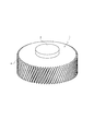
次に本発明の実施形態を説明する。図1、図2に示したように、本発明に係る内歯ギア製造用マンドレル1は、硬質金属からなり、外周面に歯型2が形成された円盤形のもので、その上面中心に円柱状の凸部3が一体に形成され、下面中心には該凸部3が摺動自在に嵌合し得る凹部4が形成されたものである。そして、該凸部3と凹部4とを互いに嵌合することにより、図3に示したように、複数のマンドレル1が同軸上に位置決めされて連なり得るようにしている。   Next, an embodiment of the present invention will be described. As shown in FIGS. 1 and 2, the mandrel 1 for manufacturing an internal gear according to the present invention is a disc-shaped member made of a hard metal and having a tooth mold 2 formed on an outer peripheral surface, and a circular shape is formed at the center of the upper surface. A columnar convex portion 3 is integrally formed, and a concave portion 4 in which the convex portion 3 can be slidably fitted is formed at the center of the lower surface. Then, by fitting the convex portion 3 and the concave portion 4 to each other, as shown in FIG. 3, the plurality of mandrels 1 can be positioned coaxially and connected to each other.

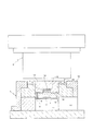
図4は該マンドレル1を使用した内歯ギア製造装置を示し、5はプレス装置、6は該プレス装置のボルスターにベースプレート5aによって固設されたダイスで、該ダイスには貫通状の円筒形空孔7が形成され、該円筒形空孔7は、上方開口縁から続く大径円筒形部分8と、該円筒形部分に続くテーパ状の縮径部9と、該縮径部9に続く小径円筒形部分10とからなり、該小径円筒形部分10の下方は下部空間11に開口し、該下部空間11の側方に取出口12が形成されている。該プレス装置5はダイス6に相対するように押圧部13がベースプレート5bに固設されていて、該押圧部13が油圧によって進出動および後退動(図では上下動)する簡単な構造のもので、該押圧部13の周縁部に前記大径円筒形部分8中に嵌入し得る外径の環状パンチ14が設けられる。15は該環状パンチ14の内側の押圧部13の中心に同軸上に形成された凹所、16は該凹所15の内底部に固設されたマグネットで、前記マンドレル1の凸部3を該凹所15に嵌入するとともに、該マグネットの磁力により該マンドレル1を吸着することにより、該マンドレル1は環状パンチ14の内側に同軸上でかつ該押圧部13から離脱可能に保持される。ここに離脱可能に保持とは、マグネット16の磁力がマンドレル1の重量を負担し得る以上でありつつも、後述するように、成形時に歯車素材から受ける引張力によっては離脱し得る程度の保持力であることをいう。   FIG. 4 shows an internal gear manufacturing apparatus using the mandrel 1, 5 is a pressing device, 6 is a die fixed to a bolster of the pressing device by a base plate 5 a, and the die has a penetrating cylindrical hollow space. A hole 7 is formed. The cylindrical hole 7 includes a large-diameter cylindrical portion 8 that continues from the upper opening edge, a tapered reduced diameter portion 9 that follows the cylindrical portion, and a small diameter that continues to the reduced diameter portion 9. The lower portion of the small-diameter cylindrical portion 10 opens into the lower space 11, and an outlet 12 is formed on the side of the lower space 11. The pressing device 5 has a simple structure in which a pressing portion 13 is fixed to the base plate 5b so as to face the die 6, and the pressing portion 13 moves forward and backward (up and down in the figure) by hydraulic pressure. An annular punch 14 having an outer diameter that can be fitted into the large-diameter cylindrical portion 8 is provided at the peripheral edge of the pressing portion 13. 15 is a recess formed coaxially in the center of the pressing portion 13 inside the annular punch 14, 16 is a magnet fixed to the inner bottom of the recess 15, and the convex portion 3 of the mandrel 1 is By inserting the mandrel 1 into the recess 15 and attracting the mandrel 1 by the magnetic force of the magnet, the mandrel 1 is held coaxially inside the annular punch 14 and detachable from the pressing portion 13. Here, the releasable holding means that the magnetic force of the magnet 16 is more than the weight of the mandrel 1 can be borne, but as will be described later, the holding force can be released depending on the tensile force received from the gear material during molding. It means that.

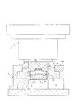
次にこの装置により内歯ギアを製造するための鍛造工程を説明する。歯車素材Wは、外径が前記大径円筒形部分8より僅かに小さく(直径差で0.1mm程度)、内径がマンドレル1の外径よりも僅かに大きい(直径差で0.1mm程度)環状に予め形成されたもので、該歯車素材Wを図4に示したように前記縮径部9上にセットする。そして図5に示したように押圧部13を圧下することにより環状パンチ14およびマンドレル1を円筒形空孔7内に進出させ、該マンドレル1を該歯車素材W内に挿入させる。そして、該環状パンチ14により歯車素材Wを押圧する。これにより図6に示したように該歯車素材Wを縮径部6に沿って内向きに塑性変形させ、該歯車素材Wを該マンドレル1を抱き込んで歯型2内に侵入させる。このように歯車素材Wがマンドレル1を抱き込んで塑性変形するとき、該歯車素材Wは軸方向にも伸びることから該歯車素材Wはその変形に従い該マンドレル1を押圧部13から離脱させる。即ち、歯車素材Wが変形するのに伴いマンドレル1が引っ張られ、その引張力は前記マグネット16による保持力より強力であることから、該マンドレル1は図6に示したように押圧部13から次第に離脱する。   Next, a forging process for manufacturing an internal gear using this apparatus will be described. The gear material W has an outer diameter slightly smaller than the large-diameter cylindrical portion 8 (diameter difference of about 0.1 mm) and an inner diameter slightly larger than the outer diameter of the mandrel 1 (diameter difference of about 0.1 mm). The gear material W is formed in an annular shape in advance, and is set on the reduced diameter portion 9 as shown in FIG. Then, as shown in FIG. 5, the annular punch 14 and the mandrel 1 are advanced into the cylindrical hole 7 by lowering the pressing portion 13, and the mandrel 1 is inserted into the gear material W. Then, the gear material W is pressed by the annular punch 14. As a result, as shown in FIG. 6, the gear material W is plastically deformed inward along the reduced diameter portion 6, and the gear material W is embraced by the mandrel 1 and enters the tooth mold 2. Thus, when the gear material W embraces the mandrel 1 and plastically deforms, the gear material W extends in the axial direction, so that the gear material W separates the mandrel 1 from the pressing portion 13 according to the deformation. That is, as the gear blank W is deformed, the mandrel 1 is pulled, and the tensile force is stronger than the holding force by the magnet 16, so that the mandrel 1 gradually moves from the pressing portion 13 as shown in FIG. break away.

次いで図7に示したように、円筒形空孔7内に該マンドレル1を残したままで環状パンチ14のみをいったん後退させ、押圧部13に新たな同形状のマンドレル1′をマグネット16により保持させる。そして先に塑性変形している歯車素材Wの上に新たな同形状の歯車素材W′をセットし、図8に示したように該環状パンチ14および新たなマンドレル1′を円筒形空孔4内に再進出させ、該歯車素材W′を同様に塑性変形をさせる。このとき、先にセットされた歯車素材Wはこの新たな歯車素材W′によってさらに押圧されることからさらに塑性変形しマンドレル1を抱き込んだ状態で該円筒形空孔4を貫通して、図9に示したように下部空間11に排出される。そして該下部空間11に排出された歯車素材Wはマンドレル1とともに取出口12から側方に取り出される。   Next, as shown in FIG. 7, with the mandrel 1 remaining in the cylindrical hole 7, only the annular punch 14 is retracted once, and a new mandrel 1 ′ having the same shape is held in the pressing portion 13 by the magnet 16. . Then, a new gear material W 'having the same shape is set on the gear material W which has been plastically deformed, and the annular punch 14 and the new mandrel 1' are connected to the cylindrical hole 4 as shown in FIG. The gear material W ′ is plastically deformed in the same manner. At this time, since the previously set gear material W is further pressed by the new gear material W ′, the plastic material is further plastically deformed and penetrates the cylindrical hole 4 in a state where the mandrel 1 is embraced. As shown in FIG. Then, the gear material W discharged into the lower space 11 is taken out sideways from the outlet 12 together with the mandrel 1.

図9に示したように先にセットされた歯車素材Wおよびマンドレル1が下部空間11に排出され、新たにセットされた歯車素材W′が塑性変形しマンドレル1′を抱き込んで歯型2内に侵入したら、該マンドレル1′を円筒形空孔7内に残したままで再び環状パンチ14を図7に示したように後退させて、押圧部13にまた新たな同形状のマンドレルをマグネット16により保持させるとともに該歯車素材W′の上にまた新たな同形状の歯車素材をセットし、該環状パンチ14およびマンドレルを円筒形空孔4内に再々進出させる。以降も同様に環状パンチ14を進出動・後退動させる度に新たなマンドレルおよび歯車素材を上記にようにセットすることにより、該歯車素材が歯型2内に侵入することで内歯が形成され、マンドレルを一体的に抱き込んだ状態で下部空間11に連続的に排出される。   As shown in FIG. 9, the previously set gear blank W and mandrel 1 are discharged into the lower space 11, and the newly set gear blank W 'is plastically deformed to embrace the mandrel 1' and within the tooth mold 2. 7, the mandrel 1 ′ remains in the cylindrical hole 7, and the annular punch 14 is retracted again as shown in FIG. 7, and a new mandrel having the same shape is again put on the pressing portion 13 by the magnet 16. At the same time, a new gear material having the same shape is set on the gear material W ′, and the annular punch 14 and the mandrel are advanced again into the cylindrical hole 4. Similarly, each time the annular punch 14 is moved forward / backward, a new mandrel and gear material are set as described above, and the gear material enters the tooth mold 2 to form internal teeth. The mandrel is continuously discharged into the lower space 11 in a state where the mandrel is integrally held.

なお、図8に示したように円筒形空孔4内に複数のマンドレルが連なっているとき、それらのマンドレルは互いの凸部3と凹部4とが軸方向に摺動自在に嵌合していることでそれらのマンドレルは常に同軸上に保持され、該マンドレルが常に円筒形空孔4の中心に位置する。このため円筒形空孔4の内周面とマンドレルの外周面との間に歯車素材が充填する空隙が高精度で形成され、成形精度を極めて高くすることができる。   As shown in FIG. 8, when a plurality of mandrels are connected in the cylindrical hole 4, the mandrels are fitted so that the convex portions 3 and the concave portions 4 are slidable in the axial direction. As a result, the mandrels are always held coaxially, and the mandrel is always located at the center of the cylindrical hole 4. Therefore, a gap filled with the gear material is formed with high accuracy between the inner peripheral surface of the cylindrical hole 4 and the outer peripheral surface of the mandrel, and the molding accuracy can be extremely increased.

また、この製造方法によれば、高ねじれ角のヘリカルギヤでも高精度に成形できるとともに、先にセットされた歯車素材が新たにセットされた歯車素材によって押圧されて縮径部6から小径円筒形部分10に移動するので、下部空間11に排出された歯車素材の外径を一様に小径円筒形部分10の内径に一致させることができる。このため、従来の歯車素材のように押し残し部が生じることなく歩留りが向上し、製造コストを軽減させる。また、この製造方法には単純なプレス装置が使用され、従来のような複雑な構造の高価な多軸複動プレス装置を必要としないので設備費も軽減される利点がある。   Further, according to this manufacturing method, even a helical gear with a high helix angle can be molded with high precision, and the previously set gear material is pressed by the newly set gear material to reduce the diameter of the small diameter cylindrical portion 6. 10, the outer diameter of the gear blank discharged into the lower space 11 can be made to match the inner diameter of the small-diameter cylindrical portion 10 uniformly. For this reason, the yield is improved without producing a non-pressing portion unlike the conventional gear material, and the manufacturing cost is reduced. In addition, since this manufacturing method uses a simple press device and does not require an expensive multi-axis double-action press device having a complicated structure as in the prior art, there is an advantage that the equipment cost can be reduced.

取出口12から取り出されたマンドレル1と一体的となった歯車素材Wは、図10に製造ラインを示したように、鍛造工程Aから機械加工工程Bに移動され、図11に示したように旋盤20のチャック21に該マンドレル1の凸部3を把持させ、バイト22を歯車素材Wの所要外周部分や端部に当てることによりこれらの部分が切削加工される。このようにマンドレル1を抱き込んだ状態で排出された歯車素材Wから該マンドレル1を分離することなく該マンドレル1の凸部3をチャック21により把持し、該マンドレル1を証として歯車素材Wを機械加工することにより、該歯車素材Wに成形された内歯と該機械加工部分との同芯性が保たれるので、加工精度を向上させ、不良品をなくし、高精度の内歯ギアが容易に製造されるようになる。   The gear material W integrated with the mandrel 1 taken out from the outlet 12 is moved from the forging step A to the machining step B as shown in FIG. 10, and as shown in FIG. By causing the chuck 21 of the lathe 20 to grip the convex portion 3 of the mandrel 1 and applying the cutting tool 22 to a required outer peripheral portion or end portion of the gear material W, these portions are cut. The protrusion 3 of the mandrel 1 is gripped by the chuck 21 without separating the mandrel 1 from the gear material W discharged in the state where the mandrel 1 is held in this way, and the gear material W is By machining, the concentricity between the internal teeth formed in the gear material W and the machined portion is maintained, so that machining accuracy is improved, defective products are eliminated, and high-precision internal gears are produced. It becomes easy to manufacture.

次いで、これを機械加工工程Cに移動し、マンドレル1の凸部3を取外し機構(図示せず)により把持固定し、歯車素材Wの一端面を軸方向に押し込むことにより、該歯車素材Wが回転しながら該マンドレル1から分離する。そして必要に応じ、図12に示したように、旋盤23のチャック24により該歯車素材Wの外周部分を把持し、該歯車素材Wの端部や内周面の一部にバイト25を当てて該歯車素材Wの端部や内周面が切削加工され、さらにバリ取り工程Dに移されてバリ取りが行われた後、検査工程Eに移動され、出来上がった内歯ギアの製品検査をする。   Next, this is moved to the machining step C, the convex portion 3 of the mandrel 1 is removed and held and fixed by a mechanism (not shown), and one end face of the gear material W is pushed in the axial direction. The mandrel 1 is separated while rotating. If necessary, as shown in FIG. 12, the outer peripheral portion of the gear material W is gripped by the chuck 24 of the lathe 23, and the cutting tool 25 is applied to an end portion of the gear material W or a part of the inner peripheral surface. The end portion and inner peripheral surface of the gear material W are cut and further transferred to a deburring process D to be deburred, and then moved to an inspection process E to inspect the finished internal gear product. .

一方、機械加工工程Cにて分離されたマンドレル1は鍛造工程Aに戻され再使用される。このため本発明に係るマンドレルは、一つの製造ラインについて予め数個から十数個備えておき、これら複数のマンドレルを鍛造工程Aと機械加工工程Cとの間で循環させることで、内歯ギアを連続的に製造することが可能となり生産効率を高められる。   On the other hand, the mandrel 1 separated in the machining step C is returned to the forging step A and reused. For this reason, the mandrel according to the present invention is provided with several to a dozen or more in advance for one production line, and the plurality of mandrels are circulated between the forging process A and the machining process C, thereby providing an internal gear. Can be manufactured continuously, and production efficiency can be improved.

なお、この実施形態ではマンドレルをマグネット16によって押圧部13に保持するようにしたが、マンドレルの保持はこの実施形態のような磁力による吸着のほか、押圧部13に真空吸着部材を設けてマンドレルを真空吸着し、その吸着力が上記引張力よりも弱くなるように設定することでマンドレルを離脱可能に保持してもよい。或いは、押圧部13に保持力が上記引張力よりも弱いように設定し得る機械的なチャッキング機構を設けることで、マンドレルを離脱可能に保持してもよい。   In this embodiment, the mandrel is held on the pressing portion 13 by the magnet 16. However, the mandrel is held by the magnetic force as in this embodiment, or a vacuum suction member is provided on the pressing portion 13 to hold the mandrel. The mandrel may be detachably held by vacuum suction and setting the suction force to be weaker than the tensile force. Alternatively, the mandrel may be detachably held by providing the pressing portion 13 with a mechanical chucking mechanism that can be set so that the holding force is weaker than the tensile force.

1,1′ マンドレル
2 歯型
3 凸部
4 凹部
5 プレス装置
6 ダイス
7 円筒形空孔
8 大径円筒形部分
9 縮径部
10 小径円筒形部分
11 下部空間
12 取出口
13 押圧部
14 環状パンチ
15 凹所
16 マグネット
20 旋盤
21 チャック
W,W′ 歯車素材
1, 1 'Mandrel 2 Tooth mold 3 Convex part 4 Concave part 5 Press device 6 Die 7 Cylindrical hole 8 Large-diameter cylindrical part 9 Reduced-diameter part 10 Small-diameter cylindrical part 11 Lower space 12 Outlet 13 Pressing part 14 Circular punch 15 Recess 16 Magnet 20 Lathe 21 Chuck W, W 'Gear material

Claims (5)

外周面に歯型が形成された円盤形のマンドレルであって、プレス装置の押圧部に設けたマグネットの磁力により重量が負担されることで該押圧部に設けた環状パンチの内側に同軸上に保持される一方、成形時に歯車素材から受ける引張力によっては該押圧部から離脱するように離脱可能な保持手段を備えていることを特徴とする内歯ギア製造用マンドレル。 A disk-shaped mandrel having a tooth shape formed on the outer peripheral surface thereof, and is coaxial with the inner side of the annular punch provided in the pressing portion by bearing the weight by the magnetic force of the magnet provided in the pressing portion of the pressing device. A mandrel for manufacturing an internal gear, comprising : holding means that can be detached so as to be detached from the pressing portion depending on a tensile force received from a gear material during molding. 貫通状の円筒形空孔の内周面にテーパ状の縮径部が形成されたダイスをプレス装置に配設し、該ダイスと相対する該プレス装置の押圧部に環状パンチを設け、外周面に歯型が形成された円盤形のマンドレルが該環状パンチの内側に同軸上でかつ成形時に歯車素材から受ける引張力によっては該プレス装置の押圧部から離脱可能に保持され、前記縮径部上に環状の歯車素材をセットして前記環状パンチおよび前記マンドレルを該円筒形空孔内に進出させることにより、該マンドレルを該歯車素材内に挿入するとともに該環状パンチにより該歯車素材を軸方向に押圧し該歯車素材を前記縮径部に沿って内向きに塑性変形させることにより該歯車素材が該マンドレルを抱き込んで外周面の歯型内に侵入し、該歯車素材がマンドレルを抱き込んで塑性変形するのに従い該マンドレルは該プレス装置の押圧部から離脱し、次いで該マンドレルを円筒形空孔内に残したまま該環状パンチを後退させて該プレス装置の押圧部に新たな同形状のマンドレルを保持させるとともに、先にセットされた歯車素材上に新たな同形状の歯車素材をセットしてから該環状パンチおよび新たなマンドレルを円筒形空孔内に進出させることにより、新たにセットされた歯車素材は新たなマンドレルを抱き込んで塑性変形し、先にセットされた歯車素材は新たにセットされた歯車素材によってさらに押圧されることによりさらに塑性変形してマンドレルを抱き込んだ状態で該円筒形空孔を貫通し排出されるようにしたことを特徴とする内歯ギアの製造方法。 A die having a tapered reduced diameter portion formed on the inner peripheral surface of the through-hole-shaped cylindrical hole is disposed in the press device, and an annular punch is provided in the pressing portion of the press device facing the die, and the outer peripheral surface A disc-shaped mandrel having a tooth shape formed on the inner side of the annular punch is held coaxially within the annular punch and detachable from the pressing portion of the pressing device depending on the tensile force received from the gear material during molding. An annular gear blank is set on the annular punch and the mandrel is advanced into the cylindrical hole so that the mandrel is inserted into the gear blank and the gear blank is axially moved by the annular punch. By pressing and plastically deforming the gear material inward along the reduced diameter portion, the gear material embraces the mandrel and enters the tooth mold on the outer peripheral surface, and the gear material embraces the mandrel. Plasticity As it is formed, the mandrel is released from the pressing part of the pressing device, and then the annular punch is retracted while leaving the mandrel in the cylindrical hole to form a new mandrel of the same shape in the pressing part of the pressing device. And setting a new gear material of the same shape on the previously set gear material and then advancing the annular punch and a new mandrel into the cylindrical hole. The gear material embracs a new mandrel and plastically deforms, and the previously set gear material is further pressed by the newly set gear material to further plastically deform and embed the mandrel. A method for manufacturing an internal gear, characterized in that it is discharged through a shaped hole. 請求項2に記載したマンドレルは、前記押圧部に設けたマグネットの磁力により重量が負担されることで該押圧部に設けた環状パンチの内側に同軸上に保持される一方、成形時に歯車素材から受ける引張力によっては該押圧部から離脱するように保持されていることを特徴とした内歯ギアの製造方法。 The mandrel described in claim 2 is held coaxially inside the annular punch provided in the pressing portion by being borne by the magnet's magnetic force provided in the pressing portion. A method for manufacturing an internal gear, wherein the internal gear is held so as to be detached from the pressing portion depending on a tensile force received . マンドレルを抱き込んだ状態で排出された歯車素材からマンドレルを分離することなく該マンドレルを把持して該歯車素材を機械加工することを特徴とする請求項2または3に記載した内歯ギアの製造方法。 4. The manufacturing of an internal gear according to claim 2, wherein the gear material is machined by gripping the mandrel without separating the mandrel from the gear material discharged in a state where the mandrel is held. Method. プレス装置と、貫通状の円筒形空孔の内周面にテーパ状の縮径部が形成されたダイスと、該ダイスと相対する該プレス装置の押圧部に設けられた環状パンチと、複数の請求項1に記載した内歯ギア製造用マンドレルとを具備してなることを特徴とする内歯ギアの製造装置。 A pressing device, a die having a tapered reduced diameter portion formed on the inner peripheral surface of a through-hole cylindrical hole, an annular punch provided in a pressing portion of the pressing device facing the die, and a plurality of punches An internal gear manufacturing apparatus comprising the internal gear manufacturing mandrel according to claim 1 .
JP2010136217A 2010-06-15 2010-06-15 Mandrel for manufacturing internal gear and method and apparatus for manufacturing internal gear using the mandrel Expired - Fee Related JP5609291B2 (en)

Priority Applications (1)

Application Number Priority Date Filing Date Title
JP2010136217A JP5609291B2 (en) 2010-06-15 2010-06-15 Mandrel for manufacturing internal gear and method and apparatus for manufacturing internal gear using the mandrel

Applications Claiming Priority (1)

Application Number Priority Date Filing Date Title
JP2010136217A JP5609291B2 (en) 2010-06-15 2010-06-15 Mandrel for manufacturing internal gear and method and apparatus for manufacturing internal gear using the mandrel

Publications (3)

Publication Number Publication Date
JP2012000625A JP2012000625A (en) 2012-01-05
JP2012000625A5 JP2012000625A5 (en) 2013-04-18
JP5609291B2 true JP5609291B2 (en) 2014-10-22

Family

ID=45533241

Family Applications (1)

Application Number Title Priority Date Filing Date
JP2010136217A Expired - Fee Related JP5609291B2 (en) 2010-06-15 2010-06-15 Mandrel for manufacturing internal gear and method and apparatus for manufacturing internal gear using the mandrel

Country Status (1)

Country Link
JP (1) JP5609291B2 (en)

Families Citing this family (5)

* Cited by examiner, † Cited by third party
Publication number Priority date Publication date Assignee Title
JP5742527B2 (en) * 2011-07-13 2015-07-01 大同特殊鋼株式会社 Mandrel for manufacturing internal helical gear, internal helical gear manufacturing apparatus, and internal helical gear manufacturing method
CN103480787A (en) * 2013-09-27 2014-01-01 江苏太平洋精锻科技股份有限公司 Hot forging forming die for synchronous gear rings
CN106141056A (en) * 2015-04-09 2016-11-23 昌利锻造有限公司 A kind of forging mold
CN106141058A (en) * 2015-04-15 2016-11-23 昌利锻造有限公司 One combines gear ring forging mold
CN106141057A (en) * 2015-04-15 2016-11-23 昌利锻造有限公司 A kind of enclosed circle die holder

Family Cites Families (3)

* Cited by examiner, † Cited by third party
Publication number Priority date Publication date Assignee Title
JPH01170544A (en) * 1987-12-26 1989-07-05 M H Center:Kk Plastic working device for helical internal gear
US5465597A (en) * 1994-07-18 1995-11-14 Ford Motor Company Extrusion forming of internal helical splines
JP2005342779A (en) * 2004-06-07 2005-12-15 Fuji Univance Corp Method for forming gear

Also Published As

Publication number Publication date
JP2012000625A (en) 2012-01-05

Similar Documents

Publication Publication Date Title
US9302317B2 (en) Method for manufacturing hollow engine valve
EP2131995B1 (en) Powder metal forging and method of manufacture
JP5609291B2 (en) Mandrel for manufacturing internal gear and method and apparatus for manufacturing internal gear using the mandrel
JP2006305599A (en) Method and apparatus for forming bevel gear by forging
US20080104843A1 (en) Method and Device for Forging Bevel Gear
KR100817044B1 (en) Method and apparatus for manufacturing input shaft
JP2012000625A5 (en)
JP5742527B2 (en) Mandrel for manufacturing internal helical gear, internal helical gear manufacturing apparatus, and internal helical gear manufacturing method
JP5080359B2 (en) Manufacturing method of hollow tooth profile parts
JP5099877B2 (en) Forming method of forged products
JP2010042440A (en) Method of manufacturing grooved bolt
JP2010064100A (en) Gear production device and method for producing the same
EP1716940B1 (en) Method of preparing a gear structure
JP2006305600A (en) Method and apparatus for forming bevel gear by forging
JPH07144247A (en) Die for forging part with steps and method thereof
JP2008284566A (en) Apparatus for forging teeth having crowning
JP6797917B2 (en) A method of manufacturing a tooth by molding, and a tool device for calibrating a tooth inlet and / or a tooth outlet.
CN212216802U (en) Pole hexagonal head stamping die
JP5707417B2 (en) Method for manufacturing molded part with through hole
JP4764951B1 (en) Method for manufacturing hose fittings
JP4828989B2 (en) Upsetting method
JP4495187B2 (en) CROWNING GEAR MANUFACTURING METHOD
JPS62238040A (en) Cold forming method for hollow shaft like part with flange
JP2005161364A (en) Method for forming involute serration on hollow shaft
JP2001205384A (en) Method for forming gear with boss

Legal Events

Date Code Title Description
A521 Written amendment

Free format text: JAPANESE INTERMEDIATE CODE: A523

Effective date: 20130228

A621 Written request for application examination

Free format text: JAPANESE INTERMEDIATE CODE: A621

Effective date: 20130426

A131 Notification of reasons for refusal

Free format text: JAPANESE INTERMEDIATE CODE: A131

Effective date: 20140225

A977 Report on retrieval

Free format text: JAPANESE INTERMEDIATE CODE: A971007

Effective date: 20140227

A521 Written amendment

Free format text: JAPANESE INTERMEDIATE CODE: A523

Effective date: 20140421

A977 Report on retrieval

Free format text: JAPANESE INTERMEDIATE CODE: A971007

Effective date: 20140424

TRDD Decision of grant or rejection written
A01 Written decision to grant a patent or to grant a registration (utility model)

Free format text: JAPANESE INTERMEDIATE CODE: A01

Effective date: 20140805

A61 First payment of annual fees (during grant procedure)

Free format text: JAPANESE INTERMEDIATE CODE: A61

Effective date: 20140818

R150 Certificate of patent or registration of utility model

Ref document number: 5609291

Country of ref document: JP

Free format text: JAPANESE INTERMEDIATE CODE: R150

LAPS Cancellation because of no payment of annual fees