JP5607464B2 - Objective lens unit and ophthalmic imaging apparatus - Google Patents
Objective lens unit and ophthalmic imaging apparatus Download PDFInfo
- Publication number
- JP5607464B2 JP5607464B2 JP2010197268A JP2010197268A JP5607464B2 JP 5607464 B2 JP5607464 B2 JP 5607464B2 JP 2010197268 A JP2010197268 A JP 2010197268A JP 2010197268 A JP2010197268 A JP 2010197268A JP 5607464 B2 JP5607464 B2 JP 5607464B2
- Authority
- JP
- Japan
- Prior art keywords
- objective lens
- optical system
- black spot
- photographing
- illumination light
- Prior art date
- Legal status (The legal status is an assumption and is not a legal conclusion. Google has not performed a legal analysis and makes no representation as to the accuracy of the status listed.)
- Expired - Fee Related
Links
Images


Classifications
-
- A—HUMAN NECESSITIES
- A61—MEDICAL OR VETERINARY SCIENCE; HYGIENE
- A61B—DIAGNOSIS; SURGERY; IDENTIFICATION
- A61B3/00—Apparatus for testing the eyes; Instruments for examining the eyes
- A61B3/10—Objective types, i.e. instruments for examining the eyes independent of the patients' perceptions or reactions
- A61B3/14—Arrangements specially adapted for eye photography
- A61B3/145—Arrangements specially adapted for eye photography by video means
-
- A—HUMAN NECESSITIES
- A61—MEDICAL OR VETERINARY SCIENCE; HYGIENE
- A61B—DIAGNOSIS; SURGERY; IDENTIFICATION
- A61B3/00—Apparatus for testing the eyes; Instruments for examining the eyes
- A61B3/10—Objective types, i.e. instruments for examining the eyes independent of the patients' perceptions or reactions
- A61B3/12—Objective types, i.e. instruments for examining the eyes independent of the patients' perceptions or reactions for looking at the eye fundus, e.g. ophthalmoscopes
Landscapes
- Health & Medical Sciences (AREA)
- Life Sciences & Earth Sciences (AREA)
- Engineering & Computer Science (AREA)
- Medical Informatics (AREA)
- Surgery (AREA)
- Biophysics (AREA)
- Biomedical Technology (AREA)
- Heart & Thoracic Surgery (AREA)
- Physics & Mathematics (AREA)
- Molecular Biology (AREA)
- Ophthalmology & Optometry (AREA)
- Animal Behavior & Ethology (AREA)
- General Health & Medical Sciences (AREA)
- Public Health (AREA)
- Veterinary Medicine (AREA)
- Multimedia (AREA)
- Eye Examination Apparatus (AREA)
Description
本発明は、対物レンズを含む主光学系と、前記対物レンズを主光学系と共有する照明光学系とを有する眼科撮影装置に用いられる対物レンズユニット、および該対物レンズユニットを用いる眼底カメラなどの眼科撮影装置に関するものである。 The present invention relates to an objective lens unit used in an ophthalmologic photographing apparatus having a main optical system including an objective lens and an illumination optical system sharing the objective lens with the main optical system, and a fundus camera using the objective lens unit. The present invention relates to an ophthalmologic photographing apparatus.
眼底カメラなどの眼科撮影装置において、被検眼を照明するために、ハロゲンランプやフラッシュのような照明光源を用い、観察および撮影のための主光学系対物レンズを共有する照明光源部を配置する構成が知られている。 In an ophthalmologic imaging apparatus such as a fundus camera, an illumination light source such as a halogen lamp or a flash is used to illuminate an eye to be examined, and an illumination light source unit that shares a main optical system objective lens for observation and imaging is arranged It has been known.
蛍光撮影時には強い照明光が必要であり、また秒1コマ程度のインターバルで撮影が行なわれるため、照明光源およびその近辺は非常に高温になり、そのため本体筐体に熱による歪みを発生させるなどの問題がある。 Fluorescent photography requires strong illumination light, and photography takes place at an interval of about 1 frame per second, so the illumination light source and its vicinity become extremely hot, which causes distortion of the main body case due to heat, etc. There's a problem.
この問題に鑑み、照明光源部を眼科撮影装置の本体上部に配置する構成が提案されている(下記の特許文献1)。さらに、この特許文献1では照明光を反射させる穴あきミラーの反射面を装置の下方を向くように配置すべく、撮影光路と照明光路を交差させた複雑な光路配置を採用している。 In view of this problem, the structure which arrange | positions an illumination light source part in the main body upper part of an ophthalmic imaging device is proposed (patent document 1 below). Further, in this Patent Document 1, a complicated optical path arrangement is adopted in which the photographing optical path and the illumination optical path are crossed so that the reflection surface of the perforated mirror that reflects the illumination light faces the lower side of the apparatus.
特許文献1では、このように撮影光路と照明光路を交差させた光路配置を採用する理由として、照明光源部を眼科撮影装置の本体上部に配置するために照明光を反射させる穴あきミラーの反射面を単純に装置の上方に向けただけの構成では、埃によって穴あきミラーの反射が損なわれる問題が認識されている。 In Patent Document 1, as a reason for adopting an optical path arrangement in which the imaging optical path and the illumination optical path intersect in this way, the reflection of the perforated mirror that reflects the illumination light in order to arrange the illumination light source unit on the main body of the ophthalmic imaging apparatus. A problem has been recognized in which the reflection of the perforated mirror is impaired by dust in a configuration in which the surface is simply directed upward.
照明光源部を眼科撮影装置の本体上部に配置するのは、上述の熱の問題の回避、および埃の問題の回避に有効であると考えられるが、特許文献1のような穴あきミラーを下向きにして再度照明光学系を折り曲げて照明光源を上部に配置する構成は複雑高価になりがちで、また、特許文献1のように撮影光路と照明光路を交差させた光路配置では撮影光や観察光にフレアなどが入り易い、という問題がある。 Although it is considered that placing the illumination light source unit on the upper part of the main body of the ophthalmologic photographing apparatus is effective in avoiding the above-described heat problem and the dust problem, the perforated mirror as in Patent Document 1 faces downward. Then, the configuration in which the illumination optical system is bent again and the illumination light source is arranged at the top tends to be complicated and expensive. There is a problem that flare and the like are likely to enter.
また、眼底カメラなどの眼科撮影装置では、眼底撮影時の撮影光が対物レンズで反射してその反射光が撮影および観察に影響するのを防止するために、遮光部材から成る黒点を設けた黒点板を照明光路中に配置することが行なわれている。この黒点板の対物レンズや撮影絞り、穴あきミラーなどの光学系に対する相対位置関係は精密に行なう必要があり、眼科撮影装置の組立、調整、あるいは保守作業時において、たとえば対物レンズ廻りの部品を取り外した場合には再度黒点板の位置を精密に調整し直さなければならない、という問題があった。 Further, in an ophthalmologic photographing apparatus such as a fundus camera, in order to prevent photographing light at the time of fundus photographing from being reflected by an objective lens and affecting the photographing and observation, a black spot provided with a black spot composed of a light shielding member is provided. Placing the plate in the illumination light path is performed. The relative position of the black spot plate with respect to the optical system such as the objective lens, the photographing aperture, and the perforated mirror must be precisely set. For example, when the ophthalmic photographing apparatus is assembled, adjusted, or maintained, the parts around the objective lens are removed. When it was removed, there was a problem that the position of the black spot plate had to be precisely adjusted again.
本実施例の課題は、照明光源部を眼科撮影装置の本体上部に配置する構成において、照明光を反射させる穴あきミラーの反射面を装置の上方に向ける単純な光路配置を用いながら、穴あきミラーの埃の問題を回避し、かつ眼科撮影装置の組立、調整、あるいは保守作業時における対物レンズの反射を防止する黒点板と光学系の位置関係の問題を解決し、眼科撮影装置を簡単安価に構成でき、安定した眼科撮影を行なえるようにすることにある。 The problem of the present embodiment is that, in the configuration in which the illumination light source unit is arranged at the upper part of the main body of the ophthalmologic photographing apparatus, a simple optical path arrangement in which the reflection surface of the perforated mirror that reflects the illumination light is directed upward is used. Eliminates the problem of mirror dust and solves the problem of the positional relationship between the black spot plate and the optical system, which prevents reflection of the objective lens during assembly, adjustment, or maintenance of the ophthalmic imaging apparatus, and makes the ophthalmic imaging apparatus simple and inexpensive. It is to be able to perform stable ophthalmic photography.
上記課題を解決するため、本発明においては、対物レンズを含む主光学系と、前記対物レンズを主光学系と共有する照明光学系とを有する眼科撮影装置に用いられる対物レンズユニットにおいて、前記対物レンズを通過する撮影光または観察光を中央の開口から出射させる開口を有するとともに、前記主光学系の光軸に対して傾斜して配置され、前記照明光学系からの照明光を反射面で反射させる穴あきミラーと、前記穴あきミラーの開口を通過した撮影光または観察光を通過させる撮影絞りと、前記穴あきミラーの反射面に照明光を入射させるための照明光学系の光軸上に前記照明光の前記対物レンズ表面での反射を防止する黒点を配置するための黒点板と、前記対物レンズを収容する第1の鏡筒と、前記黒点板を固定した第2の鏡筒を前記主光学系と前記照明光学系の光軸が交差するように屈曲した姿勢で一体に組合せた形状の鏡筒ユニットを含み、前記対物レンズ、前記穴あきミラー、前記撮影絞り、および前記黒点板が前記鏡筒ユニットに組み付けられて一体化されることによりこれらの各部材の位置関係が保証される構成を採用した。 In order to solve the above problems, in the present invention, in the objective lens unit used in an ophthalmologic photographing apparatus having a main optical system including an objective lens and an illumination optical system sharing the objective lens with the main optical system, the objective It has an aperture that emits the imaging light or observation light that passes through the lens from the central aperture, and is inclined with respect to the optical axis of the main optical system, and reflects the illumination light from the illumination optical system on the reflection surface On the optical axis of the illumination optical system for making the illumination light incident on the reflecting surface of the perforated mirror and the aperture stop for allowing the imaging light or observation light that has passed through the aperture of the perforated mirror to pass. A black spot plate for arranging a black spot for preventing the illumination light from reflecting on the surface of the objective lens, a first lens barrel for housing the objective lens, and a second lens barrel to which the black spot plate is fixed are arranged in front. Including a lens barrel unit integrally formed in a posture bent so that the optical axes of the main optical system and the illumination optical system intersect, and the objective lens, the perforated mirror, the photographing aperture, and the black spot plate A configuration is adopted in which the positional relationship of these members is guaranteed by being assembled and integrated with the lens barrel unit.
また、眼科撮影装置に上記対物レンズユニットを装着する場合、前記穴あきミラーの反射面で反射される照明光を照射する照明光源部が装置本体の上部に配置されるとともに、装置本体の上方を向くように前記対物レンズユニットが装置本体に装着され、上方から入射する前記照明光源部の照明光が前記穴あきミラーの反射面で前記対物レンズの方向に反射される構成を採用した。 In addition, when the objective lens unit is attached to the ophthalmologic photographing apparatus, an illumination light source unit that irradiates illumination light reflected by the reflecting surface of the perforated mirror is disposed on the upper part of the apparatus body, and the upper part of the apparatus body The objective lens unit is mounted on the apparatus main body so as to face, and the illumination light of the illumination light source unit incident from above is reflected by the reflecting surface of the perforated mirror in the direction of the objective lens.
上記対物レンズユニットにおいては、前記対物レンズ、前記穴あきミラー、前記撮影絞り、および前記黒点板が前記鏡筒ユニットに組み付けられて一体化される構成となっているため、精密な位置決めの必要な反射防止用の黒点板と、他の主光学系の部材、すなわち対物レンズ、穴あきミラー、あるいはさらに撮影絞りとの位置関係を保証することができ、眼底カメラの組立、調整、あるいは保守作業は極めて容易になる。 In the objective lens unit, since the objective lens, the perforated mirror, the photographing aperture, and the black spot plate are assembled and integrated with the lens barrel unit, precise positioning is necessary. It can guarantee the positional relationship between the anti-reflection black spot plate and other main optical system members, i.e. objective lens, perforated mirror, or even the aperture stop. It becomes extremely easy.
また、上記眼科撮影装置においては、発熱の問題を回避すべく照明光源部を眼底カメラ本体の上部に配置するための穴あきミラーの反射面を装置の上方に向ける単純な光路配置を用いながら、穴あきミラーの埃の問題を回避し、眼科撮影装置を簡単安価に構成でき、安定した眼科撮影を行なえる、という優れた効果がある。 Further, in the above ophthalmologic photographing apparatus, while using a simple optical path arrangement in which the reflecting surface of the perforated mirror for arranging the illumination light source unit on the upper part of the fundus camera main body is directed upward of the apparatus in order to avoid the problem of heat generation, There is an excellent effect that the problem of dust on the perforated mirror can be avoided, the ophthalmologic photographing apparatus can be simply and inexpensively configured, and stable ophthalmic photographing can be performed.
以下、図面に示す眼底カメラの一実施例に基づき、本発明を実施するための好適な実施形態につき詳細に説明する。本実施例の眼底カメラは対物レンズを含む主光学系と、前記対物レンズを主光学系と共有する照明光学系とを有する。 DESCRIPTION OF EMBODIMENTS Hereinafter, a preferred embodiment for carrying out the present invention will be described in detail based on an example of a fundus camera shown in the drawings. The fundus camera of this embodiment includes a main optical system including an objective lens and an illumination optical system that shares the objective lens with the main optical system.
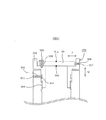
図1〜図3は本発明を採用した眼科撮影装置として眼底カメラの一実施例の概略構成を示しており、図1は本発明を採用した眼底カメラの主に光学系の概略構成を、図2は図1のレンズユニットの構成を、図3は図1および図2のレンズユニットの黒点板の装着機構をそれぞれ示している。 1 to 3 show a schematic configuration of an embodiment of a fundus camera as an ophthalmologic photographing apparatus adopting the present invention, and FIG. 1 is a diagram showing a schematic configuration of an optical system mainly of a fundus camera adopting the present invention. 2 shows the configuration of the lens unit of FIG. 1, and FIG. 3 shows the mounting mechanism of the black spot plate of the lens unit of FIGS.
本実施例において、特徴的なのは観察・撮影のための主光学系の対物レンズと主光学系の光軸と同軸の照明光を反射させる穴あきミラー、および照明光の対物レンズ境界面での反射を除去する黒点板、撮影絞りなどを1つのレンズユニットの筐体内に一体化した構成を採用している点である。 In this embodiment, the main features are an objective lens of the main optical system for observation and photographing, a perforated mirror that reflects illumination light coaxial with the optical axis of the main optical system, and reflection of the illumination light at the boundary surface of the objective lens. In other words, a configuration is adopted in which a black spot plate, a photographing aperture, and the like are integrated in the housing of one lens unit.
以下、本実施例の光学系につき、図1〜図3を参照して説明する。 Hereinafter, the optical system of the present embodiment will be described with reference to FIGS.
図1において符号Cは眼底カメラ本体の筐体の外形を示しており、図1は眼底カメラの光学系の断面構成を概略的に示している。 In FIG. 1, symbol C indicates the outer shape of the housing of the fundus camera body, and FIG. 1 schematically shows the cross-sectional configuration of the optical system of the fundus camera.
主光学系の光軸と同軸の照明光を照射する照明光源部のユニットは、図1では眼底カメラ本体から分離した形で示してあるが、実際には筐体Cの上部の空間内の所定の装着位置に装着される。このように照明光源部を筐体Cの上部に配置するのは、上述の発熱の問題を回避するためである。 The unit of the illumination light source unit that emits illumination light coaxial with the optical axis of the main optical system is shown in a form separated from the fundus camera body in FIG. It is mounted at the mounting position. The reason why the illumination light source unit is arranged in the upper part of the housing C is to avoid the above-described problem of heat generation.
照明光源部内には、観察用光源であるランプLA、撮影光源としてのストロボSR、赤外光を透過させ可視光をカットする挿脱自在のフィルタF、コンデンサーレンズ1、主光学系の方向に照明光を反射させるミラーM2、コンデンサーレンズ2bなどが配置される。 In the illumination light source section, a lamp LA as an observation light source, a strobe SR as a photographing light source, a detachable filter F that transmits infrared light and cuts visible light, a condenser lens 1, and illuminates in the direction of the main optical system. A mirror M2 that reflects light, a condenser lens 2b, and the like are disposed.
照明光源部の装着状態において、ランプLAはミラーM2の中心を向けて配置され、このランプLAから発せられた光は、フィルタFの挿脱位置、ストロボSRの位置を経てコンデンサーレンズ1、全反射ミラーM2により反射され、コンデンサーレンズ2bを経て、眼底カメラの筐体Cの下方に向けて照射される。 In the mounted state of the illumination light source unit, the lamp LA is arranged with the center of the mirror M2 directed, and the light emitted from the lamp LA passes through the insertion / removal position of the filter F and the position of the strobe SR, and the condenser lens 1 is totally reflected. The light is reflected by the mirror M2 and irradiated through the condenser lens 2b toward the lower side of the housing C of the fundus camera.
図中の符号2aは、上記のコンデンサーレンズ2bと同じもので、照明光源部の装着状態におけるコンデンサーレンズ2bの配置位置を示している。
照明光源部の照明光は、リング状照明を形成するためのリングスリット4a、レンズ5を経て、さらに下方に進む。リングスリット4a、レンズ5は筐体C内に設けられる。リングスリット4aは、不図示のターレット機構などを用いて、異なるスリット形状を有するいくつかの別のリングスリット4bと撮影モードに応じて交換できるようになっている。
Illumination light from the illumination light source unit travels further downward through a ring slit 4a and a
さらに照明光源部の照明光は、眼底カメラの筐体下部の所定位置に装着される対物レンズユニット100に入射する。
Further, the illumination light from the illumination light source unit enters the
対物レンズユニット100は、主に対物レンズ8、穴あきミラーM3、および対物レンズ8の境界面での反射を除去する黒点板30、リレーレンズ7、撮影絞りなどを1つのレンズユニットの筐体内に一体化して構成されている。
The
対物レンズユニット100は、図1および図2に示すように対物レンズ8を収容する第1の鏡筒(図中の水平部分)と、黒点板30を固定する第2の鏡筒(図中の上方を向く部分)を前記主光学系と前記照明光学系の光軸が交差するように屈曲した姿勢で一体に組合せた形状、すなわちほぼV字型の形状を有する、鏡筒ユニットを含む。
As shown in FIGS. 1 and 2, the
そして、対物レンズユニット100は、対物レンズ8を収容した第1の鏡筒の部分を水平方向に向け、また、黒点板30を固定する第2の鏡筒の光軸が装置上方の照明光源部からの照明光学系の光軸と一致するように眼底カメラの筐体C下部の所定位置に装着される。
In the
レンズ5を経た照明光源部の照明光は、対物レンズ8の反射を除去するための黒点(遮光部材)31を備えた黒点板30、リレーレンズ7を通過し、中心に穴の開いた穴あきミラー(反射部材)M3で反射されてから対物レンズ8を経て、不図示の被検眼の瞳からその眼底に入射される。被検眼は、観察・撮影時に、不図示のアライメント機構により対物レンズ8の光軸上に位置決めされる。
The illumination light of the illumination light source section that has passed through the
対物レンズユニット100の構成については、より詳細に後述する。
The configuration of the
不図示の被検眼の眼底からの反射光(観察光または撮影光)は再び被検眼の瞳から対物レンズ8を介して受光され、穴あきミラーM3の中央の開口から出射され、穴あきミラーM3の背後に配置された撮影絞り32で絞られ、合焦レンズ9、変倍レンズ10aを通過して、ミラーM5に入射し、筐体C内上方に反射される。変倍レンズ10aは、不図示のターレット機構などを介して他の倍率のいくつかの変倍レンズ10bと交換することができる。あるいは変倍レンズ10aはズーム系などから構成してもよい。
Reflected light (observation light or imaging light) from the fundus of the eye to be examined (not shown) is received again from the pupil of the eye to be examined through the
ミラーM5により反射された観察・撮影光はリターンミラーM6の位置を通過する。リターンミラーM6、不図示の駆動手段を介して光路から外せるように構成されており、リターンミラーM6が光路に挿入されている場合には接眼レンズ50を介して検者が被検眼の眼底の映像を観察することができる。なお、リターンミラーM6の位置には、後述のCCDカメラ26ないし24での撮影時の視野を規制する視野絞り(不図示)を挿入できるようにしておいてもよい。
The observation / photographing light reflected by the mirror M5 passes through the position of the return mirror M6. The return mirror M6 is configured so that it can be removed from the optical path through a driving means (not shown). Can be observed. It should be noted that a field stop (not shown) for restricting the field of view at the time of photographing with the
リターンミラーM6が光路から除去されている場合には、観察・撮影光はフィールドレンズ21を経て、リターン式のミラーM7(あるいはダイクロイックミラーなどを用いることもできる)で反射され、観察用の(赤外)CCDカメラ26に入射する。ミラーM7が光路から離脱される場合は、観察・撮影光はレンズ23、ミラーM8を経てCCDカメラ24に入射し、眼底像が撮影される。(カラー)CCDカメラ24は、既成のデジタルカメラハードウェアなどを用いたもので、当該カメラ24の仕様と合致したレンズマウント24aを介して眼底カメラに装着される。
When the return mirror M6 is removed from the optical path, the observation / photographing light passes through the
CCDカメラ(ユニット)24、26で撮像された眼底の動画あるいは静止画は、記録装置やモニタ(いずれも不図示)に記録したりあるいは表示される。 The fundus moving image or still image captured by the CCD cameras (units) 24 and 26 is recorded or displayed on a recording device or a monitor (both not shown).
このような眼底カメラでは、全反射ミラー(反射部材)である穴あきミラーM3と被検眼の間で照明光路の一部と観察撮影光路の一部が共通化されており、眼底観察時には、照明光源部に赤外光を透過させ可視光をカットするフィルタFが光路に挿入され、眼底が照明光学系により照明される。なおフィルタFは可視光で眼底観察を行う時には光路から離脱できるように構成されている。 In such a fundus camera, part of the illumination optical path and part of the observation photographing optical path are shared between the perforated mirror M3, which is a total reflection mirror (reflection member), and the eye to be examined. A filter F that transmits infrared light through the light source and cuts visible light is inserted into the optical path, and the fundus is illuminated by the illumination optical system. The filter F is configured so as to be able to leave the optical path when performing fundus observation with visible light.
眼底からの反射光が、撮影光学系を介して(赤外)CCDカメラ26に入射し眼底画像が動画像として観察される。アライメントや合焦が終了すると、ミラーM6が光路から離脱されるとともに、ストロボSRが発光し、眼底画像が(カラー)CCDカメラ24で撮影される。CCDカメラ24で撮影される場合には、ミラーM6のみならずミラーM7も光路から離脱される。
Reflected light from the fundus enters the (infrared)
次に、本実施例の対物レンズユニット100に係る構成につき詳細に説明する。
Next, a configuration related to the
眼底カメラでは、眼底撮影時の撮影光が対物レンズ8で反射してその反射光が撮影画像上に写り込んでしまうために、これを防止するために、照明光路中に遮光部材(後述の黒点31)を、対物レンズの各面の反射光によって生じる撮影絞り像の位置にほぼ共役な位置に配置する。
In the fundus camera, the photographing light at the time of fundus photographing is reflected by the
たとえば、図2、図3に示したように、表裏に黒点31a、31bを設けた平面ガラスから成る黒点板30を配置することによって、対物レンズ8の表裏それぞれの面からの反射光によって撮影絞り像が生じることを防止する。黒点31a、31bは不透明材料を黒点板30の表面に付着させることなどにより構成するが、円筒状の不透明材を黒点板30に貫通させる、など公知の他の構造を採用してもよい。
For example, as shown in FIGS. 2 and 3, by arranging a
黒点31a、31bは、対物レンズ8の表裏面の反射を各々除去するために、対物レンズ8および撮影絞り32を含む光学系において撮影絞り32と共役な位置に正確に配置する必要がある。
The
本実施例では、図2に示すようにV字型の対物レンズユニット100の上部の入射部に黒点板30を組み込んで対物レンズユニット100と一体化することにより、対物レンズ8との位置関係を予め固定化することができる。
In the present embodiment, as shown in FIG. 2, the
さらに、本実施例では、黒点板30の光軸に対する位置を調節するために図3のような調節機構を設けている。このような調節機構を設けておくことにより、個々の対物レンズユニット100ごとに黒点板30の光軸に対する位置関係を正確に調節した上、予め固定化することができ、黒点板30の正確な配置位置を保証することができる。
Further, in this embodiment, an adjusting mechanism as shown in FIG. 3 is provided to adjust the position of the
図3に示した黒点板30の調節機構300は、対物レンズユニット100の上部鏡筒(第2の鏡筒)に装着され、黒点板30を保持する黒点板マウント304を含む。
3 includes a black
黒点板マウント304は、その下端のスクリユー部309において、対物レンズユニット100の上部鏡筒に捻じ込まれており、黒点板マウント304を回転させることにより黒点板マウント304の高さ(Q方向に関する位置)を調節することができる。たとえばスクリユー部309のねじ山ピッチを1mm以内程度としておけば、1回転の範囲内で黒点板マウント304の高さは精密に調節することができる。
The black
黒点板マウント304の高さ方向(Q)が決まったら、その位置は、対物レンズユニット100の上部鏡筒のネジ穴301に捻じ込まれたセットビス302により黒点板マウント304を固定することができる。黒点板マウント304下部の鏡筒部分の周囲には、セットビス302の固定範囲を上下方向(Q)に規制できるようにリング状の溝303を切っておいてもよい。
When the height direction (Q) of the black
また、黒点板マウント304上部の皿状に形成された部分には黒点板30が載置され、その光軸と交差する方向(P)の位置は黒点板マウント304上部のフランジに設けたネジ穴307に捻じ込まれたセットビス308により調整できる。ここでは、簡略化のためセットビス308は図中に1本しか示していないが、もちろん、この1本のみならず、黒点板マウント304上部のフランジ周囲に規則的に3〜4本配置しておく構成を採用してもよく、これにより、これらのセットビスを用いて黒点板30の照明光軸と交差する方向(P)の位置の調整(芯出し)を精密に行なうことができる。
Further, the
この黒点板30の照明光軸と交差する方向(P)の位置の調整(芯出し)が終了したら、その黒点板30の位置は、黒点板30の貫通穴306を貫通するロックビス305により固定することができる。
When the adjustment (centering) of the position in the direction (P) intersecting the illumination optical axis of the
上記のQおよびP方向の黒点板30の位置の調節は、たとえば不図示の所定の調整用光学系に対物レンズユニット100を装着した上で、調整用光学系を介して黒点31a、31bの位置を確認しながら行なうことができる。
The adjustment of the position of the
黒点板30の黒点31a、31bの対物レンズ8および撮影絞り32を含む光学系における配置位置は、光学系の倍率の関係から精密に調節する必要がある。本実施例のように黒点板30、対物レンズ8、撮影絞り32を一体化した対物レンズユニット100を用いず、眼底カメラ内に黒点板30を配置する従来構成では、眼底カメラの組立、調整、あるいは保守作業時に眼底カメラごとに黒点板30の配置位置を調整しなければならず煩雑な作業が必要であった。
The arrangement position of the
これに対して、本実施例のような黒点板30、対物レンズ8、穴あきミラーM3、撮影絞り32を一体化した対物レンズユニット100を用いることにより、正確に配置した黒点板30を有する対物レンズユニット100を予め組立てておくことができる。また、保守(あるいは修理)作業時などに対物レンズを取り外す必要が生じても、本実施例では対物レンズユニット100全体を眼底カメラから取り外せばよく、再度対物レンズ8および撮影絞り32を含む光学系に対する黒点板30の配置位置が狂わなくて済む。
On the other hand, by using the
以上のように、本実施例のように黒点板30、対物レンズ8、穴あきミラーM3、撮影絞り32を一体化した対物レンズユニット100を用いることにより、対物レンズユニット100を眼底カメラの所定位置に組み込むだけで精密な黒点31a、31bの位置を保証することができる。
As described above, by using the
また、本実施例においては、照明光を反射させる穴あきミラーM3と、撮影絞り32が対物レンズユニット100に一体的に組み込まれているので、これら穴あきミラーM3および撮影絞り32の対物レンズ8に対する位置も固定的に保証することができる。これにより、眼底カメラの組立、調整、あるいは保守作業は極めて容易になる。
In the present embodiment, the perforated mirror M3 for reflecting the illumination light and the photographing
また、特に、穴あきミラーM3を対物レンズユニット100に一体的に封入しておくことにより、防塵効果を期待することができ、埃によって穴あきミラーM3の反射効率が損なわれたり、黒点やリングスリットの結像状態が悪化する問題を大きく軽減することができる。なお、撮影絞り32には中心部に絞り穴が設けられるが、通常この直径は2mm前後(あるいはそれ以下)であり、本実施例の対物レンズユニット100は、穴あきミラーM3や撮影絞り32を眼底カメラ内にオープン配置する構成に比してかなり大きな防塵効果を発揮することができる。
In particular, when the perforated mirror M3 is integrally enclosed in the
また、上記のように、撮影絞り32の開口は通常2mm前後(あるいはそれ以下)と小さく、そのままでもかなりの防塵効果を期待できるが、撮影絞り32の背面に、破線(図1)で示したように、防塵ガラス32aを配置し、対物レンズユニット100のV字型鏡筒全体をより密閉性の高い防塵構造とすることもできる。
Further, as described above, the aperture of the photographing
以上のように、本実施例によれば、眼底カメラに対物レンズ8、撮影絞り32、および黒点板30を一体化した対物レンズユニット100を用いることにより、精密な位置決めの必要な黒点板30と、他の主光学系の部材、すなわち対物レンズ8、撮影絞り32との位置関係を保証することができ、眼底カメラの組立、調整、あるいは保守作業は極めて容易になる。
As described above, according to the present embodiment, by using the
また、発熱の問題を回避すべく照明光源部を眼底カメラ本体の上部に配置するための穴あきミラーM3の反射面を装置の上方に向ける単純な光路配置を用いながら、穴あきミラーの埃の問題を回避し、眼科撮影装置を簡単安価に構成でき、安定した眼科撮影を行なえる、という優れた効果がある。 Further, in order to avoid the problem of heat generation, while using a simple optical path arrangement in which the reflecting surface of the perforated mirror M3 for arranging the illumination light source unit on the upper part of the fundus camera body is directed upward of the apparatus, There are excellent effects that the problem can be avoided, the ophthalmologic photographing apparatus can be configured simply and inexpensively, and stable ophthalmic photographing can be performed.
また、図3に示すような黒点板30の位置を調節し、所定位置に固定するための調節機構300を設けることにより、あらかじめ対物レンズユニット100を組み立てる際に、予め対物レンズユニット100ごとに黒点板30の位置を正確に決定することができ、対物レンズユニット100を所定位置に組み込むだけで精密な位置決めの必要な黒点板30と、他の主光学系の部材、すなわちレンズ8、撮影絞り32との位置関係を保証することができ、眼科撮影装置の保守や修理のために対物レンズ廻りの分解が必要になって対物レンズユニット100を着脱しても、再度黒点板30の位置を調節する必要がない、という大きな利点がある。
Further, by providing an
なお、黒点板30の相対位置を精密に調整しなければならないのは対物レンズ8、穴あきミラーM3、撮影絞り32などに対してであり、一方、対物レンズユニット100全体と他の光学系部分の組み付け精度は黒点板30の相対位置ほどには要求されないため、本実施例の対物レンズユニット100のような一体構造を採用することよって、眼底カメラの組立、調整、あるいは保守作業を簡略化し、しかも黒点板30の相対位置の精度を保てる、という大きな利点がある。
The relative position of the
なお、以上では表裏に遮光部材から成る黒点31a、31bをそれぞれ付着させた1枚のガラス板から成る黒点板(あるいは円筒状の黒点を貫通させた黒点板)を例示したが、対物レンズ8の表裏(あるいは接合レンズの場合は他の境界面)にそれぞれ対応してそれぞれ黒点を付着させた黒点板を2枚(あるいはそれ以上)配置するような構成を用いてもよい。その場合、2枚(あるいはそれ以上)の黒点ガラスは、それぞれ独立して照明光軸に対する配置位置を調節できるような調整機構を用いるようにすると良い。要するに、照明光の対物レンズ8の境界面における反射の影響を除去する黒点板の構成、およびその位置の調節機構は任意であり、対物レンズユニット100の鏡筒ユニットに対する黒点板の固定位置を調整する調整機構を設けることによって本発明の構成を実施することができる。
In the above, a black spot plate made of a single glass plate (or a black spot plate penetrating a cylindrical black spot) with
C 筐体
1 コンデンサーレンズ
2 ミラーM
M3 穴あきミラー
4a、4b リングスリット
5 レンズ
M6 リターンミラー
7 リレーレンズ
M7 ミラー
8 対物レンズ
9 合焦レンズ
23 レンズ
24 CCDカメラ
30 黒点板
31 黒点(遮光部材)
32 撮影絞り
32a 防塵ガラス
50 接眼レンズ
100 対物レンズユニット
300 調節機構
301 ネジ穴
302 セットビス
303 溝
304 黒点板マウント
305 ロックビス
306 貫通穴
307 ネジ穴
308 セットビス
309 スクリユー部
C Case 1
32
Claims (4)
前記対物レンズを通過する撮影光または観察光を中央の開口から出射させる開口を有するとともに、前記主光学系の光軸に対して傾斜して配置され、前記照明光学系からの照明光を反射面で反射させる穴あきミラーと、
前記穴あきミラーの開口を通過した撮影光または観察光を通過させる撮影絞りと、
前記穴あきミラーの反射面に入射される照明光の光軸上に前記照明光の前記対物レンズ表面での反射を防止する黒点を配置するための黒点板と、
前記対物レンズを収容する第1の鏡筒と、前記黒点板を固定した第2の鏡筒を前記主光学系と前記照明光学系の光軸が交差するように屈曲した姿勢で一体に組合せた形状の鏡筒ユニットを含み、
前記対物レンズ、前記穴あきミラー、前記撮影絞り、および前記黒点板が前記鏡筒ユニットに組み付けられて一体化されることによりこれらの各部材の位置関係が保証されることを特徴とする対物レンズユニット。 In an objective lens unit used in an ophthalmologic photographing apparatus having a main optical system including an objective lens and an illumination optical system sharing the objective lens with the main optical system,
It has an opening for emitting photographing light or observation light passing through the objective lens from a central opening, and is arranged inclined with respect to the optical axis of the main optical system, and reflects the illumination light from the illumination optical system as a reflection surface. With a perforated mirror to reflect on,
A photographing aperture that allows photographing light or observation light that has passed through the aperture of the perforated mirror to pass;
A black spot plate for disposing a black spot for preventing reflection of the illumination light on the objective lens surface on the optical axis of the illumination light incident on the reflection surface of the perforated mirror;
The first lens barrel that accommodates the objective lens and the second lens barrel that fixes the black spot plate are integrally combined in a posture that is bent so that the optical axes of the main optical system and the illumination optical system intersect. Including a lens barrel unit,
An objective lens characterized in that the positional relationship of these members is ensured by assembling the objective lens, the perforated mirror, the photographing aperture stop, and the black spot plate into the barrel unit. unit.
Priority Applications (2)
| Application Number | Priority Date | Filing Date | Title |
|---|---|---|---|
| JP2010197268A JP5607464B2 (en) | 2010-09-03 | 2010-09-03 | Objective lens unit and ophthalmic imaging apparatus |
| PCT/JP2011/069252 WO2012029640A1 (en) | 2010-09-03 | 2011-08-26 | Objective lens unit and ophthalmological filming device |
Applications Claiming Priority (1)
| Application Number | Priority Date | Filing Date | Title |
|---|---|---|---|
| JP2010197268A JP5607464B2 (en) | 2010-09-03 | 2010-09-03 | Objective lens unit and ophthalmic imaging apparatus |
Publications (2)
| Publication Number | Publication Date |
|---|---|
| JP2012050760A JP2012050760A (en) | 2012-03-15 |
| JP5607464B2 true JP5607464B2 (en) | 2014-10-15 |
Family
ID=45772730
Family Applications (1)
| Application Number | Title | Priority Date | Filing Date |
|---|---|---|---|
| JP2010197268A Expired - Fee Related JP5607464B2 (en) | 2010-09-03 | 2010-09-03 | Objective lens unit and ophthalmic imaging apparatus |
Country Status (2)
| Country | Link |
|---|---|
| JP (1) | JP5607464B2 (en) |
| WO (1) | WO2012029640A1 (en) |
Families Citing this family (2)
| Publication number | Priority date | Publication date | Assignee | Title |
|---|---|---|---|---|
| JP2013242413A (en) * | 2012-05-21 | 2013-12-05 | Suwa Optronics:Kk | Imaging optical system and image capturing device |
| JP6757615B2 (en) * | 2016-07-29 | 2020-09-23 | 株式会社トプコン | Ophthalmic equipment |
Family Cites Families (5)
| Publication number | Priority date | Publication date | Assignee | Title |
|---|---|---|---|---|
| JPH10272105A (en) * | 1997-03-31 | 1998-10-13 | Topcon Corp | Fundus camera |
| JPH11206711A (en) * | 1998-01-23 | 1999-08-03 | Nikon Corp | Optometry device |
| JP4619523B2 (en) * | 2000-12-05 | 2011-01-26 | 株式会社トプコン | Model eye |
| JP4512388B2 (en) * | 2004-03-15 | 2010-07-28 | 興和株式会社 | Fundus camera |
| JP5038626B2 (en) * | 2006-01-13 | 2012-10-03 | 興和株式会社 | Fundus photographing device |
-
2010
- 2010-09-03 JP JP2010197268A patent/JP5607464B2/en not_active Expired - Fee Related
-
2011
- 2011-08-26 WO PCT/JP2011/069252 patent/WO2012029640A1/en not_active Ceased
Also Published As
| Publication number | Publication date |
|---|---|
| JP2012050760A (en) | 2012-03-15 |
| WO2012029640A1 (en) | 2012-03-08 |
Similar Documents
| Publication | Publication Date | Title |
|---|---|---|
| TWI549648B (en) | Ophthalmoscope | |
| WO2009145738A1 (en) | Slit lamp with an optoelectronic slit | |
| US6317260B1 (en) | Stereoscopic microscope | |
| JP6168302B2 (en) | Corneal imaging device | |
| JP2002165759A (en) | Model eye | |
| EP2080472B1 (en) | Ophthalmic photography apparatus | |
| JP5607464B2 (en) | Objective lens unit and ophthalmic imaging apparatus | |
| JP2009110004A (en) | Illumination device for light microscope and light microscope with illumination device | |
| JP4393830B2 (en) | Stereoscopic fundus observation device | |
| US9883087B2 (en) | Objective for an image recording device | |
| JP2012181139A (en) | Lens inspection device | |
| WO2019088070A1 (en) | Scan type eyeground imaging device | |
| JP2008276230A (en) | Optical component for stereomicroscope | |
| JP2001340301A (en) | Fundus imaging device | |
| JP2016514536A (en) | Device for fundus examination | |
| SI22179A (en) | Portable slot lamp with integrated digital camera and exposure shutter | |
| JP5409410B2 (en) | Ophthalmic imaging equipment | |
| JP4300601B2 (en) | Binocular microscope and imaging method using binocular microscope | |
| JP6994764B2 (en) | Ophthalmic photography equipment | |
| JP4158092B2 (en) | 3D image adapter and 3D image capturing device mounting mechanism | |
| JPH05245109A (en) | Fundus camera | |
| JP4243938B2 (en) | 3D image adapter and 3D image capturing device mounting mechanism | |
| JP2025067804A (en) | Imaging apparatus | |
| JP2002267919A (en) | Binocular lens barrel | |
| KR20250052976A (en) | Imaging device |
Legal Events
| Date | Code | Title | Description |
|---|---|---|---|
| A621 | Written request for application examination |
Free format text: JAPANESE INTERMEDIATE CODE: A621 Effective date: 20130717 |
|
| RD03 | Notification of appointment of power of attorney |
Free format text: JAPANESE INTERMEDIATE CODE: A7423 Effective date: 20140117 |
|
| TRDD | Decision of grant or rejection written | ||
| A01 | Written decision to grant a patent or to grant a registration (utility model) |
Free format text: JAPANESE INTERMEDIATE CODE: A01 Effective date: 20140820 |
|
| A61 | First payment of annual fees (during grant procedure) |
Free format text: JAPANESE INTERMEDIATE CODE: A61 Effective date: 20140828 |
|
| R150 | Certificate of patent or registration of utility model |
Ref document number: 5607464 Country of ref document: JP Free format text: JAPANESE INTERMEDIATE CODE: R150 |
|
| R250 | Receipt of annual fees |
Free format text: JAPANESE INTERMEDIATE CODE: R250 |
|
| R250 | Receipt of annual fees |
Free format text: JAPANESE INTERMEDIATE CODE: R250 |
|
| LAPS | Cancellation because of no payment of annual fees |