JP5606161B2 - Image forming apparatus - Google Patents

Image forming apparatus Download PDF

Info

Publication number
JP5606161B2
JP5606161B2 JP2010126838A JP2010126838A JP5606161B2 JP 5606161 B2 JP5606161 B2 JP 5606161B2 JP 2010126838 A JP2010126838 A JP 2010126838A JP 2010126838 A JP2010126838 A JP 2010126838A JP 5606161 B2 JP5606161 B2 JP 5606161B2
Authority
JP
Japan
Prior art keywords
sheet
roller
feeding
feeding roller
guide member
Prior art date
Legal status (The legal status is an assumption and is not a legal conclusion. Google has not performed a legal analysis and makes no representation as to the accuracy of the status listed.)
Expired - Fee Related
Application number
JP2010126838A
Other languages
Japanese (ja)
Other versions
JP2011251807A (en
JP2011251807A5 (en
Inventor
圭介 藤田
Current Assignee (The listed assignees may be inaccurate. Google has not performed a legal analysis and makes no representation or warranty as to the accuracy of the list.)
Canon Inc
Original Assignee
Canon Inc
Priority date (The priority date is an assumption and is not a legal conclusion. Google has not performed a legal analysis and makes no representation as to the accuracy of the date listed.)
Filing date
Publication date
Application filed by Canon Inc filed Critical Canon Inc
Priority to JP2010126838A priority Critical patent/JP5606161B2/en
Publication of JP2011251807A publication Critical patent/JP2011251807A/en
Publication of JP2011251807A5 publication Critical patent/JP2011251807A5/ja
Application granted granted Critical
Publication of JP5606161B2 publication Critical patent/JP5606161B2/en
Expired - Fee Related legal-status Critical Current
Anticipated expiration legal-status Critical

Links

Images

Landscapes

  • Sheets, Magazines, And Separation Thereof (AREA)

Description

本発明は、画像形成装置に関し、特に給送ローラにより送り出されるシートを1枚ずつ分離するシート分離部の構成に関するものである。   The present invention relates to an image forming apparatus, and more particularly to a configuration of a sheet separating unit that separates sheets fed by a feeding roller one by one.

従来の画像形成装置においては、例えば電子写真画像形成方式を用いてシートに画像を形成するものがあり、このような画像形成装置は、給紙カセットに収納されたシートを画像形成部に向けて給送するためのシート給送装置を備えている。そして、シート給送装置は、例えば分離パッド等の摩擦部材であるシート分離部材を給送ローラに圧接させることによりシートの重送を防ぎ、最上位のシートのみを1枚ずつ給送するようにしたシート分離部を備えたものがある。   Some conventional image forming apparatuses form an image on a sheet using, for example, an electrophotographic image forming system. Such an image forming apparatus directs a sheet stored in a paper feed cassette toward an image forming unit. A sheet feeding device for feeding is provided. The sheet feeding device prevents the sheet from being double-fed by pressing the sheet separating member, which is a friction member such as a separation pad, against the feeding roller, and feeds only the uppermost sheet one by one. Some have a sheet separation unit.

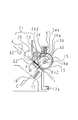
図11は、このような従来のシート分離部を備えたシート給送装置の構成を示す図である。図11において、15は中板13に載置されたシートPを1枚ずつ給送する給送ローラ、16は給送ローラ15と同軸上に設けられた給送コロ、17は分離パッドである。この分離部材である分離パッド17は、回動軸17aを支点とするホルダ17Aの回動端に取り付けられており、このホルダ17Aを分離パッドばね18によって給送ローラ側に付勢することにより、給送ローラ15又は給送コロ16に圧接する。21は、搬送ローラ19と搬送ローラ20とを備えたシート搬送ローラ対である。   FIG. 11 is a diagram illustrating a configuration of a sheet feeding apparatus including such a conventional sheet separating unit. In FIG. 11, 15 is a feeding roller for feeding sheets P placed on the intermediate plate 13 one by one, 16 is a feeding roller provided coaxially with the feeding roller 15, and 17 is a separation pad. . The separation pad 17 which is this separation member is attached to the rotation end of the holder 17A with the rotation shaft 17a as a fulcrum, and by urging the holder 17A toward the feeding roller by the separation pad spring 18, It is brought into pressure contact with the feed roller 15 or the feed roller 16. A sheet conveying roller pair 21 includes a conveying roller 19 and a conveying roller 20.

そして、このようなシート給送装置の場合、シート給送動作が開始されると、シートPは給送ローラ15によって給送された後、分離パッド17によって1枚ずつに分離される。この後、シートPは給送コロ16と分離パッド17に挟持され、シート搬送ローラ対21によって引き抜くように下流に搬送される。   In such a sheet feeding apparatus, when the sheet feeding operation is started, the sheets P are fed by the feeding roller 15 and then separated one by one by the separation pad 17. Thereafter, the sheet P is sandwiched between the feeding roller 16 and the separation pad 17 and conveyed downstream so as to be pulled out by the sheet conveying roller pair 21.

ここで、例えば小型レーザビームプリンタにおいては、シート搬送ローラ対21を、給送コロ16と分離パッド17の当接部の接線Aよりも給送コロ側に設けることにより、シート給送後のパスをコンパクトにしている。しかし、このように構成した場合、シートPの引き抜き方向は給送コロ16に巻き付く方向になる。   Here, for example, in a small laser beam printer, the path after the sheet feeding is provided by providing the sheet conveying roller pair 21 on the feeding roller side with respect to the tangent line A of the contact portion between the feeding roller 16 and the separation pad 17. Is made compact. However, when configured in this way, the drawing direction of the sheet P is a direction around the feeding roller 16.

つまり、シートPが給送コロ16と分離パッド17に挟持された状態でシート搬送ローラ対21により搬送される時、シートPの引き抜き方向は、図12に示すように給送コロ16と分離パッド17の当接部及びシート搬送ローラ対21を結んだ直線B方向になる。これにより、シート搬送ローラ対21がシートPを引き抜く時、シートPによって給送コロ16には直線B方向の力Fが働く。この力Fは、接線A方向の力Ftと法線C方向の力Fnに分解される。   That is, when the sheet P is conveyed by the sheet conveying roller pair 21 while being sandwiched between the feeding roller 16 and the separation pad 17, the drawing direction of the sheet P is as shown in FIG. The direction of the straight line B connects the contact portion 17 and the sheet conveying roller pair 21. Thereby, when the sheet conveying roller pair 21 pulls out the sheet P, a force F in the straight line B direction acts on the feeding roller 16 by the sheet P. This force F is decomposed into a force Ft in the tangential A direction and a force Fn in the normal C direction.

ここで、法線方向の力Fnは給送コロ中心16aに向かう方向であるため、シート搬送ローラ対21によりシートPが搬送引き抜かれる際、シートPにより給送コロ16を介して給送ローラ15及び給送コロ16を支持する不図示の支持部が押圧される。この結果、給送コロ16と一体に不図示の支持部が振動し、この振動により騒音が発生する可能性があった。   Here, since the force Fn in the normal direction is the direction toward the feeding roller center 16a, when the sheet P is conveyed and pulled out by the sheet conveying roller pair 21, the feeding roller 15 passes through the feeding roller 16 by the sheet P. And a support portion (not shown) that supports the feeding roller 16 is pressed. As a result, a support portion (not shown) vibrates integrally with the feeding roller 16, and noise may occur due to the vibration.

なお、このようなシート給送中の騒音の発生を低減するため、従来、例えばホルダ17Aを給送コロ側に付勢する板バネを追加し、常に分離パッドを給送コロに押し付けることにより、振動を抑えるようにしたものがある(特許文献1参照)。また、シート搬送ローラ対21によって搬送される際、給送コロと分離パッドの圧接を解除するようにしたものがある(特許文献2参照)がある。   In order to reduce the occurrence of noise during sheet feeding, conventionally, for example, a leaf spring that urges the holder 17A toward the feeding roller is added, and the separation pad is always pressed against the feeding roller. There is one that suppresses vibration (see Patent Document 1). In addition, there is one in which the pressure contact between the feeding roller and the separation pad is released when the sheet is conveyed by the sheet conveying roller pair 21 (see Patent Document 2).

特開平7−133033号公報JP-A-7-133303 特開平5−208747号公報Japanese Patent Laid-Open No. 5-208747

ところで、このような従来の画像形成装置において、板バネによって振動を抑える方法では、板バネの圧によってシートの給送性能が低下するおそれがある。また、給送コロと分離パッドの圧接を解除する方法では、分離性能が低下し、重送が発生するおそれがある。つまり、板バネによって振動を抑える方法や、給送コロと分離パッドの圧接を解除する方法では、シート給送中の騒音を抑えこむことはできるが、分離給送性能が低下する。   By the way, in such a conventional image forming apparatus, in the method of suppressing the vibration by the leaf spring, the sheet feeding performance may be lowered by the pressure of the leaf spring. Further, in the method of releasing the pressure contact between the feeding roller and the separation pad, the separation performance is deteriorated and there is a possibility that double feeding occurs. That is, in the method of suppressing vibration by the leaf spring and the method of releasing the pressure contact between the feeding roller and the separation pad, noise during sheet feeding can be suppressed, but the separation feeding performance is lowered.

そこで、本発明は、このような現状に鑑みてなされたものであり、シートの分離給送性に影響を与えることなくシート給送中の騒音の発生を抑制することのできる画像形成装置を提供することを目的とするものである。   Accordingly, the present invention has been made in view of such a current situation, and provides an image forming apparatus capable of suppressing generation of noise during sheet feeding without affecting the sheet separation and feeding performance. It is intended to do.

本発明は、周面に切り欠き部を有し、前記周面によりシートを送り出す給送ローラと、前記給送ローラの周面よりも小径に形成された給送コロと、前記給送ローラに圧接するシート分離部材と、前記給送ローラのシート給送方向下流側に設けられた湾曲したシート搬送路に設けられ、前記給送ローラにより給送されたシートを搬送するシート搬送ローラ対とを備え、給送されたシートが前記シート搬送ローラ対に到達すると、前記給送ローラを前記切り欠き部が前記シート分離部に対向し、前記給送コロと前記シート分離部材とでシートを挟持するように構成した画像形成装置において、前記給送ローラ及び前記シート分離部材により構成され、前記給送ローラにより送り出されるシートを分離するシート分離部と、前記湾曲したシート搬送路を構成し、前記シート分離部を通過したシートの先端と当接する位置に配置され、当接したシートを前記シート搬送ローラ対に向かって案内するガイド部材と、前記シート分離部及び前記シート搬送ローラ対の間で前記ガイド部材に近接する突出位置及び前記給送ローラによるシートの給送を妨げない退避位置に移動可能に設けられた突出部材と、前記突出部材を前記退避位置及び前記突出位置に移動させる移動部と、を備え、前記給送ローラにより給送されたシートが前記シート搬送ローラ対に到達する前は前記移動部により前記突出部材を前記退避位置に位置させ、給送された前記シートが前記シート搬送ローラ対に到達すると、前記移動部により前記突出部材を、前記退避位置から前記突出位置に移動させ、前記給送コロと前記シート分離部材により挟持された状態で前記シート搬送ローラ対により搬送されるシートをガイド部材側に押圧することを特徴とするものである。 The present invention provides a feed roller that has a notch in the peripheral surface and feeds a sheet by the peripheral surface, a feed roller formed with a smaller diameter than the peripheral surface of the feed roller, and the feed roller. A sheet separating member that is in pressure contact; and a sheet conveying roller pair that is provided in a curved sheet conveying path provided downstream of the feeding roller in a sheet feeding direction and that conveys a sheet fed by the feeding roller. provided, the fed sheet reaches the sheet conveying roller pair, wherein the cutout portion of the feed roller is opposed to the sheet separating member, sandwiching the sheet between the feeding roller and the sheet separating member In the image forming apparatus configured as described above, a sheet separating unit that includes the feeding roller and the sheet separating member and separates a sheet fed by the feeding roller, and the curved sheet carrying Constitute the road, the arranged sheet leading edge of the sheet which has passed through the separation unit and the abutment position, a guide member for contact with the sheet guide toward the sheet conveying roller pair, the sheet separating unit and said sheet conveying A projecting member provided between the pair of rollers so as to be movable to a projecting position close to the guide member and a retracted position that does not interfere with sheet feeding by the feeding roller; and the projecting member is moved to the retracted position and the projecting position. A moving portion that is moved to a position before the sheet fed by the feeding roller reaches the pair of sheet conveying rollers, and the protruding portion is positioned at the retracted position by the moving portion and fed. wherein when the sheet reaches the sheet transport rollers, the protrusion member by the moving unit, is moved to the projecting position from the retracted position, and the feeding roller Shi It is characterized in that for pressing the sheet to be conveyed in a state of being sandwiched by preparative separation member by the sheet conveying roller pair to the guide member.

本発明のように、シートがシート搬送ローラ対に到達すると、給送コロと分離部材により挟持された状態のシートをガイド部材側に押圧することにより、シート分離部材により給送コロを押圧する力を低減することができる。これにより、シートの分離給送性に影響を与えることなくシート給送中の騒音の発生を抑制することができる。   As in the present invention, when the sheet reaches the pair of sheet conveying rollers, the sheet pressing member is pressed against the guide member side by pressing the sheet sandwiched between the feeding roller and the separating member, thereby pressing the feeding roller with the sheet separating member. Can be reduced. As a result, the generation of noise during sheet feeding can be suppressed without affecting the sheet separation and feeding performance.

本発明の第1の実施の形態に係る画像形成装置の一例である電子写真方式のプリンタの概略構成を示す図。1 is a diagram illustrating a schematic configuration of an electrophotographic printer which is an example of an image forming apparatus according to a first embodiment of the present invention. 上記シート給送装置の構成を説明する図。The figure explaining the structure of the said sheet feeding apparatus. 上記シート給送装置の斜視図。The perspective view of the said sheet feeding apparatus. 上記シート給送装置のシート給送時の力の作用を示す図。The figure which shows the effect | action of the force at the time of sheet feeding of the said sheet feeding apparatus. 本発明の第2の実施の形態に係る画像形成装置に設けられたシート給送装置の構成を説明する図。FIG. 6 is a diagram illustrating a configuration of a sheet feeding device provided in an image forming apparatus according to a second embodiment of the present invention. 上記シート給送装置の斜視図。The perspective view of the said sheet feeding apparatus. 上記シート給送装置のシート給送時の力の作用を示す図。The figure which shows the effect | action of the force at the time of sheet feeding of the said sheet feeding apparatus. 本発明の第3の実施の形態に係る画像形成装置に設けられたシート給送装置の構成を説明する図。FIG. 10 is a diagram illustrating a configuration of a sheet feeding device provided in an image forming apparatus according to a third embodiment of the present invention. 上記シート給送装置の斜視図。The perspective view of the said sheet feeding apparatus. 上記シート給送装置のシート給送時の力の作用を示す図。The figure which shows the effect | action of the force at the time of sheet feeding of the said sheet feeding apparatus. 従来のシート給送装置の概略構成を示す図。FIG. 6 is a diagram illustrating a schematic configuration of a conventional sheet feeding apparatus. 従来のシート給送装置のシート給送時の力の作用を示す図。The figure which shows the effect | action of the force at the time of sheet feeding of the conventional sheet feeding apparatus.

以下、本発明を実施するための形態について図面を用いて詳細に説明する。図1は、本発明の第1の実施の形態に係る画像形成装置の一例である電子写真方式のプリンタの概略構成を示す図である。図1において、50はプリンタ、51はプリンタ本体、52はプリンタ本体51に設けられ、電子写真方式により画像形成を行う画像形成部、1は画像形成部52にシートPを給送するシート給送装置である。   Hereinafter, embodiments for carrying out the present invention will be described in detail with reference to the drawings. FIG. 1 is a diagram showing a schematic configuration of an electrophotographic printer which is an example of an image forming apparatus according to a first embodiment of the present invention. In FIG. 1, 50 is a printer, 51 is a printer main body, 52 is provided in the printer main body 51, an image forming unit that forms an image by electrophotography, and 1 is a sheet feeding that feeds a sheet P to the image forming unit 52 Device.

ここで、画像形成部52はトナー像を形成する感光体ドラム2、感光体ドラム2の表面を一様に帯電させる帯電ローラ3、現像スリーブ4、トナー容器5等を備え、プリンタ本体51に着脱自在に装着されているプロセスカートリッジ53を備えている。また、感光体ドラム2に形成されたトナー像をシートPに転写する転写ローラ6等を備えている。   The image forming unit 52 includes a photosensitive drum 2 that forms a toner image, a charging roller 3 that uniformly charges the surface of the photosensitive drum 2, a developing sleeve 4, a toner container 5, and the like, and is attached to and detached from the printer main body 51. A process cartridge 53 that is freely mounted is provided. Further, a transfer roller 6 for transferring the toner image formed on the photosensitive drum 2 to the sheet P is provided.

シート給送装置1は、プリンタ本体51に設けられた不図示の給紙トレイと、給紙トレイに回動自在に設けられた中板13に積載収納されたシートPを給送する周面に切り欠き部15Aを有する半月状のシート給送ローラ15を備えている。また、このシート給送ローラ(以下、給送ローラという)15の軸15aに同軸上に設けられた給送ローラ15よりも小径の給送コロ16、給送ローラ15により送り出されたシートPを分離するシート分離部54を備えている。   The sheet feeding apparatus 1 has a sheet feeding tray (not shown) provided in the printer main body 51 and a circumferential surface for feeding sheets P stacked and stored on a middle plate 13 rotatably provided on the sheet feeding tray. A half-moon shaped sheet feeding roller 15 having a notch 15A is provided. Further, the feeding roller 16 having a smaller diameter than the feeding roller 15 provided coaxially with the shaft 15a of the sheet feeding roller (hereinafter referred to as the feeding roller) 15 and the sheet P fed by the feeding roller 15 are fed. A sheet separation unit 54 for separation is provided.

ここで、給送ローラ15は1回転制御により、バネ13aによって給送ローラ側に付勢されている中板13から1枚ずつシートPを送り出すことができる。なお、給送ローラ15及び給送コロ16は不図示の支持部により回転自在に支持されている。また、図1において、21はシート分離部54のシート搬送方向下流側に設けられたシート搬送ローラ対である。   Here, the feeding roller 15 can feed the sheets P one by one from the intermediate plate 13 urged toward the feeding roller by the spring 13a by one rotation control. The feed roller 15 and the feed roller 16 are rotatably supported by a support unit (not shown). In FIG. 1, reference numeral 21 denotes a sheet conveying roller pair provided on the downstream side of the sheet separating unit 54 in the sheet conveying direction.

シート分離部54は、給送ローラ15に圧接するシート分離部材である分離パッド17と、分離パッド17を給送ローラ15に圧接するように保持する分離パッドホルダ17Aを備えている。この分離パッドホルダ17Aは、分離パッド17よりもシート給送方向上流の回動軸17aによりプリンタ本体51に回動自在に支持されると共に、分離パッドばね18によって給送ローラ15に向けて付勢されている。なお、本実施の形態では、分離パッド17は、分離パッドばね18により、給送ローラ15によりシートを送り出すときは給送ローラ15に圧接するように付勢され、給送ローラ15によりシートが送り出された後は、給送コロ16に圧接するように付勢される。   The sheet separation unit 54 includes a separation pad 17 that is a sheet separation member that is in pressure contact with the feeding roller 15, and a separation pad holder 17 </ b> A that holds the separation pad 17 in pressure contact with the feeding roller 15. The separation pad holder 17A is rotatably supported by the printer main body 51 by a rotation shaft 17a upstream of the separation pad 17 in the sheet feeding direction, and is urged toward the feeding roller 15 by the separation pad spring 18. Has been. In this embodiment, the separation pad 17 is urged by the separation pad spring 18 so as to come into pressure contact with the feeding roller 15 when the sheet is fed by the feeding roller 15, and the sheet is fed by the feeding roller 15. After being pushed, it is urged to press against the feeding roller 16.

次に、このような構成のプリンタ50における画像形成動作について説明する。トナーが転写されるシートPが給紙トレイの中板13上にセットされた後、プリント開始信号が入力されると、図示しない駆動ギア列によって駆動力を与えられ、給送ローラ15が1回転駆動されると共に、シート搬送ローラ対21、感光体ドラム2等が駆動される。   Next, an image forming operation in the printer 50 having such a configuration will be described. When a print start signal is input after the sheet P to which toner is transferred is set on the intermediate plate 13 of the paper feed tray, a driving force is applied by a driving gear train (not shown), and the feeding roller 15 rotates once. While being driven, the sheet conveying roller pair 21 and the photosensitive drum 2 are driven.

ここで、給送ローラ15が回転すると、給送ローラ15の軸15aには、回動自在な中板13の位置を規制する不図示の給紙カムが取り付けられており、この給紙カムも給送ローラ15と共に回転する。そして、このような給紙カムの回転に連動して中板13は上方回動し、シートPを給送ローラ15に押し付ける。これにより、まず中板13上にセットされたシートPのうちの最上位シートP1が、給送ローラ15との摩擦により送り出される。   Here, when the feed roller 15 rotates, a feed cam (not shown) that regulates the position of the rotatable intermediate plate 13 is attached to the shaft 15a of the feed roller 15. It rotates with the feeding roller 15. Then, the intermediate plate 13 rotates upward in conjunction with the rotation of the sheet feeding cam and presses the sheet P against the feeding roller 15. As a result, first, the uppermost sheet P <b> 1 of the sheets P set on the intermediate plate 13 is sent out by friction with the feeding roller 15.

一方、給送ローラ15が回転すると同時に、分離パッドばね18により付勢された分離パッド17によって最上位のシートP1が、分離パッド17によって次のシートと分離される。これにより、最上位のシートP1のみがシート搬送ローラ対21によって画像形成部52に搬送されていく。なお、給送ローラ15の1回転駆動終了直前には、給紙カムが中板13を給紙待機位置まで押し下げる。また、シートP1がシート搬送ローラ対21に到達すると、給送ローラ15は、切り欠き部15AがシートP1に面する状態となり、シートP1から離間すると共に、シートPの重送を防ぐように給送コロ16に分離パッド17が当接する。つまり、シートP1がシート搬送ローラ対21に到達すると、給送ローラ15の切り欠き部15Aが分離パッド17に対向するようになると共に、給送コロ16と分離パッド17とにより、シートP1を挟持する状態となる。   On the other hand, simultaneously with the rotation of the feeding roller 15, the uppermost sheet P 1 is separated from the next sheet by the separation pad 17 by the separation pad 17 biased by the separation pad spring 18. Thus, only the uppermost sheet P1 is conveyed to the image forming unit 52 by the sheet conveying roller pair 21. Note that immediately before the rotation of the feeding roller 15 is completed, the sheet feeding cam pushes the intermediate plate 13 down to the sheet feeding standby position. When the sheet P1 reaches the sheet conveying roller pair 21, the feeding roller 15 is in a state in which the notch 15A faces the sheet P1, is separated from the sheet P1, and is fed so as to prevent the sheet P from being double-fed. The separation pad 17 comes into contact with the feeding roller 16. That is, when the sheet P1 reaches the sheet conveying roller pair 21, the notch 15A of the feeding roller 15 faces the separation pad 17, and the sheet P1 is sandwiched between the feeding roller 16 and the separation pad 17. It becomes a state to do.

次に、シートP1がシート搬送ローラ対21により搬送されると、所定のタイミングでレーザー露光装置7が、帯電ローラ3によって表面が一様に帯電された感光体ドラム2にレーザー光を照射し、感光体ドラム2上に静電潜像を形成する。この後、現像スリーブ4が回転する。これにより、トナー容器5の中に充填されたトナーTが、現像スリーブ4の回転に伴って適度の帯電を受けた後、感光体ドラム2上に供給され、感光ドラム2上の静電潜像に付着する。これにより、潜像が現像され、トナー像として可視化され、この後、可視化された感光体ドラム2上のトナー像は転写ローラ6によりシートP1上に転写される。なお、シートP1に転写されずに感光体ドラム2上に残った転写残トナーは不図示のクリーニングブレードによりプロセスカートリッジ53に設けられた廃トナー容器27に収納される。また、このように表面をクリーニングされた感光体ドラム2は繰り返し次の画像形成プロセスに入る。   Next, when the sheet P1 is conveyed by the sheet conveying roller pair 21, the laser exposure device 7 irradiates the photosensitive drum 2 whose surface is uniformly charged by the charging roller 3 with a laser beam at a predetermined timing. An electrostatic latent image is formed on the photosensitive drum 2. Thereafter, the developing sleeve 4 rotates. As a result, the toner T filled in the toner container 5 is appropriately charged with the rotation of the developing sleeve 4 and then supplied to the photosensitive drum 2, and the electrostatic latent image on the photosensitive drum 2 is supplied. Adhere to. As a result, the latent image is developed and visualized as a toner image. Thereafter, the visualized toner image on the photosensitive drum 2 is transferred onto the sheet P 1 by the transfer roller 6. Note that the untransferred toner remaining on the photosensitive drum 2 without being transferred to the sheet P1 is stored in a waste toner container 27 provided in the process cartridge 53 by a cleaning blade (not shown). Further, the photosensitive drum 2 whose surface has been cleaned in this manner repeatedly enters the next image forming process.

次に、トナー像が形成されたシートP1は、加熱装置8と加圧ローラ9とからなる定着装置10に搬送され、この定着装置10において加熱、加圧されることにより、シートP1上にトナー像が永久定着される。そして、このように画像が定着された後、シートP1は排紙ローラ11と排紙コロ12に挟持、搬送され、排出積載トレイ26に排出される。   Next, the sheet P1 on which the toner image is formed is conveyed to a fixing device 10 including a heating device 8 and a pressure roller 9, and is heated and pressed by the fixing device 10, whereby the toner is formed on the sheet P1. The image is permanently fixed. After the image is fixed in this manner, the sheet P1 is sandwiched and conveyed between the paper discharge roller 11 and the paper discharge roller 12, and is discharged to the discharge stack tray 26.

図2はシート給送装置1の構成を説明する図であり、図3はシート給送装置1の斜視図である。図2及び図3において、22は第1シートガイド部材、23は第2シートガイド部材である。この第1シートガイド部材22は、シート分離部54のシート給送方向下流側に設けられ、分離されたシートをシート搬送ローラ対21に案内する湾曲したシート搬送路Rを構成するガイド部材である。   FIG. 2 is a diagram illustrating the configuration of the sheet feeding apparatus 1, and FIG. 3 is a perspective view of the sheet feeding apparatus 1. 2 and 3, reference numeral 22 denotes a first sheet guide member, and reference numeral 23 denotes a second sheet guide member. The first sheet guide member 22 is a guide member that is provided on the downstream side of the sheet separating unit 54 in the sheet feeding direction and constitutes a curved sheet conveyance path R that guides the separated sheet to the sheet conveyance roller pair 21. .

なお、この第1シートガイド部材22は、給送ローラ15とシート搬送ローラ対21の間に、シート搬送ローラ対21のニップ部に対し精度よく設けられ、給送されたシートPの分離パッド17側をガイドする。また突出部材である第2シートガイド部材23は、給送ローラ15とシート搬送ローラ対21の間に設けられ、給送されたシートPの給送コロ16側をガイドする。ここで、シート搬送ローラ対21は、搬送ローラ19,20により構成されており、ニップ部は、図2に示すように、給送コロ16と分離パッド17の当接部において給送コロ16の当接面に対して引かれる接線(延長線)Aよりも給送コロ側に設けられている。   The first sheet guide member 22 is provided between the feeding roller 15 and the sheet conveying roller pair 21 with high accuracy with respect to the nip portion of the sheet conveying roller pair 21, and the separation pad 17 for the fed sheet P. Guide the side. The second sheet guide member 23 that is a protruding member is provided between the feeding roller 15 and the sheet conveying roller pair 21 and guides the feeding roller 16 side of the fed sheet P. Here, the sheet conveying roller pair 21 is constituted by conveying rollers 19 and 20, and the nip portion of the feeding roller 16 is in contact with the feeding roller 16 and the separation pad 17 as shown in FIG. 2. It is provided closer to the feeding roller than the tangent line (extension line) A drawn to the contact surface.

第2シートガイド部材23は、給送ローラ15の動作中は、図2において実線で示す、接線A上よりも給送コロ側の退避位置Eに保持される。また、第2シートガイド部材23は、給送ローラ15のシート給送動作を終了すると、破線で示す、退避位置Eから接線A上(延長線上)、もしくは接線Aよりも第1シートガイド部材22に近接する方向に突出する突出位置Dに移動する。なお、このように突出位置Dに移動した際、第2シートガイド部材23と第1シートガイド部材22との間にはシートの給送を妨げないような間隙が形成される。   During operation of the feed roller 15, the second sheet guide member 23 is held at the retracted position E on the feed roller side from the tangent line A, which is indicated by a solid line in FIG. Further, when the sheet feeding operation of the feeding roller 15 is completed, the second sheet guide member 23 is located on the tangent line A (extended line) from the retracted position E or indicated by the broken line, or on the first sheet guide member 22 from the tangent line A. It moves to the projecting position D projecting in the direction of approaching. When moving to the protruding position D in this way, a gap is formed between the second sheet guide member 23 and the first sheet guide member 22 so as not to prevent sheet feeding.

28は退避位置E又は、第2シートガイド部材22に近接する突出位置Dに移動可能な第2シートガイド部材23を、退避位置E又は突出位置Dに移動させる移動部を構成するソレノイドである。ソレノイド28がONとなると、第2シートガイド部材23は退避位置Eに保持され、OFFとなると突出位置Dに移動する。なお、本実施の形態において、ソレノイド28は、給送ローラ15が動作中はON、給送ローラ15が動作を終了するとOFFとなる。つまり、ソレノイド28は、給送ローラ15の制御を利用して同調的にON・OFFされ、これに伴い第2シートガイド部材23は退避位置E又は突出位置Dに移動する。   Reference numeral 28 denotes a solenoid that constitutes a moving unit that moves the second sheet guide member 23 movable to the retracted position E or the projecting position D close to the second sheet guide member 22 to the retracted position E or the projecting position D. When the solenoid 28 is turned on, the second sheet guide member 23 is held at the retracted position E, and when it is turned off, the second sheet guide member 23 moves to the protruding position D. In the present embodiment, the solenoid 28 is turned on while the feeding roller 15 is in operation, and turned off when the feeding roller 15 finishes the operation. That is, the solenoid 28 is turned ON / OFF synchronously using the control of the feeding roller 15, and accordingly, the second sheet guide member 23 moves to the retracted position E or the protruding position D.

そして、このような構成のシート給送装置1において、給送ローラ15が回転すると、中板13に載置されたシートPは給送ローラ15によって送り出され、分離パッドばね18によって給送ローラ15に押圧された分離パッド17により、1枚毎に分離される。なお、分離パッド17は、一般的にコルクを含有したウレタンゴム等から構成されると共に、その表面摩擦係数、接触角度、形状は1度の給送動作毎に最上位のシート、1枚のみを搬送することができるように調整されている。また、シートPを給送した後、分離パッド17は給送コロ16に圧接してシートPを挟持する。   In the sheet feeding apparatus 1 having such a configuration, when the feeding roller 15 rotates, the sheet P placed on the intermediate plate 13 is fed out by the feeding roller 15 and is fed by the separation pad spring 18. The sheets are separated one by one by the separation pad 17 pressed against the sheet. The separation pad 17 is generally made of urethane rubber or the like containing cork, and the surface friction coefficient, contact angle, and shape of the top sheet and only one sheet for each feeding operation. It is adjusted so that it can be transported. Further, after the sheet P is fed, the separation pad 17 presses against the feeding roller 16 and sandwiches the sheet P.

次に、給送されたシートPは第1シートガイド部材22によってガイドされ、シート搬送ローラ対21まで給送される。そして、シート搬送ローラ対21によってシートPが搬送開始されると、シートPは分離パッド17と給送コロ16で挟持されたまま引き抜くように搬送される。   Next, the fed sheet P is guided by the first sheet guide member 22 and is fed to the sheet conveying roller pair 21. When the conveyance of the sheet P is started by the sheet conveyance roller pair 21, the sheet P is conveyed so as to be pulled out while being held between the separation pad 17 and the feeding roller 16.

このとき既述したように、シート搬送ローラ対21は給送コロ16と分離パッド17の当接部において給送コロ16の当接面に対して引かれる接線Aよりも、給送コロ側に設けられている。この場合、シートPの引き抜き方向は給送コロ16に巻き付く方向になる。ここで、シートPの給送コロ16側をガイドする第2シートガイド部材23が無い場合、シート搬送ローラ対21がシートPを搬送する際、分離パッド17を給送コロ16に押し付ける力を発生させながらシートPが引き抜かれるようになる。このような場合、給送コロ16と一体に不図示の支持部が振動し、この振動により騒音が発生するおそれがある。   At this time, as described above, the sheet conveying roller pair 21 is closer to the feeding roller than the tangent line A drawn to the contact surface of the feeding roller 16 at the contact portion between the feeding roller 16 and the separation pad 17. Is provided. In this case, the drawing direction of the sheet P is a direction around the feeding roller 16. Here, when there is no second sheet guide member 23 that guides the feeding roller 16 side of the sheet P, a force that presses the separation pad 17 against the feeding roller 16 is generated when the sheet conveying roller pair 21 conveys the sheet P. Then, the sheet P is pulled out. In such a case, a support portion (not shown) vibrates integrally with the feeding roller 16, and noise may be generated by this vibration.

しかし、本実施の形態においては、給送ローラ15が動作を終了し、シートPがシート搬送ローラ対21に到達して搬送され始めると、ソレノイド28がOFFとなり、図4に示すように、第2シートガイド部材23が退避位置Eから突出位置Dに移動する。これにより、シートPが第2シートガイド部材23により押圧されて第1シートガイド部材側に移動し、これに伴いシートPの引き抜き方向は、給送コロ16と分離パッド17の当接部と第2シートガイド部材23の先端とを結ぶ直線B1の方向になる。つまり、シートPが給送コロ16と分離パッド17に挟持された状態でシート搬送ローラ対21によって搬送される時、第2シートガイド部材23の移動により、シートPの引き抜き方向は接線Aよりも分離パッド側(シート分離部材側)の直線B1の方向になる。   However, in the present embodiment, when the feeding roller 15 finishes operating and the sheet P reaches the sheet conveying roller pair 21 and begins to be conveyed, the solenoid 28 is turned OFF, and as shown in FIG. The two-sheet guide member 23 moves from the retracted position E to the protruding position D. As a result, the sheet P is pressed by the second sheet guide member 23 and moves to the first sheet guide member side. Accordingly, the sheet P is pulled out in the direction in which the feeding roller 16 and the separation pad 17 are in contact with each other. It becomes the direction of the straight line B1 which connects the front-end | tip of the 2 sheet | seat guide member 23. FIG. That is, when the sheet P is conveyed by the sheet conveying roller pair 21 while being sandwiched between the feeding roller 16 and the separation pad 17, the drawing direction of the sheet P is more than the tangent line A due to the movement of the second sheet guide member 23. The direction is the straight line B1 on the separation pad side (sheet separation member side).

そして、このように引き抜き方向が直線B1の方向になると、シート搬送ローラ対21がシートPを引き抜く時、シートPによって分離パッド17には直線B1の方向の力F1が働く。この力F1は、接線A方向の力Ft1と、法線C方向の力Fn1に分解されるが、この法線方向の力Fn1は給送コロ中心16aから離れる方向になる。   When the drawing direction becomes the direction of the straight line B1 in this way, when the sheet conveying roller pair 21 pulls out the sheet P, a force F1 in the direction of the straight line B1 acts on the separation pad 17 by the sheet P. This force F1 is decomposed into a force Ft1 in the tangential A direction and a force Fn1 in the normal C direction, but this normal direction force Fn1 is away from the feeding roller center 16a.

このため、シート搬送ローラ対21がシートPを引き抜くように搬送する際、シートPの引き抜き力によって分離パッド17を給送コロ16に押し付けながら搬送することが無くなる。この結果、給送コロ16と一体に支持部が振動することがなくなり、騒音の発生を防止することができる。   For this reason, when the sheet conveying roller pair 21 conveys the sheet P so as to pull out the sheet P, the separation pad 17 is not conveyed while being pressed against the feeding roller 16 by the pulling force of the sheet P. As a result, the support portion does not vibrate integrally with the feeding roller 16, and the generation of noise can be prevented.

なお、シートPがシート搬送ローラ対21に搬送されるまでは、図2に示すように第2シートガイド部材23は、ソレノイド28によって退避位置Eに保持されるため、シート先端が第2シートガイド部材23に衝突することはない。また、給送ローラ15がシートPを給送するとき、第2シートガイド部材23がシートPと当接することもないので、第2シートガイド部材23が給送抵抗になることはなく、良好な給送性能を実現できる。   Until the sheet P is conveyed to the sheet conveying roller pair 21, the second sheet guide member 23 is held at the retracted position E by the solenoid 28 as shown in FIG. There is no collision with the member 23. Further, when the feeding roller 15 feeds the sheet P, the second sheet guide member 23 does not come into contact with the sheet P, so that the second sheet guide member 23 does not become a feeding resistance and is good. Feeding performance can be realized.

以上説明したように、本実施の形態ではシートがシート搬送ローラ対21により搬送される時は、第2シートガイド部材23を突出位置に移動させ、シートPを第1シートガイド部材側に押圧するようにしている。これにより、シートの引き抜き方向が分離パッド側に変更されるようになり、シートPの引き抜きによって分離パッド17を給送コロ16に押し付ける力が発生することなくなる。このため、シート搬送ローラ対21がシートを分離パッド17と給送コロ16で挟持されたまま搬送する際の騒音の発生を低減することができる。   As described above, in the present embodiment, when the sheet is conveyed by the sheet conveying roller pair 21, the second sheet guide member 23 is moved to the protruding position and the sheet P is pressed toward the first sheet guide member. I am doing so. Thereby, the drawing direction of the sheet is changed to the separation pad side, and the force for pressing the separation pad 17 against the feeding roller 16 by the drawing of the sheet P is not generated. For this reason, it is possible to reduce the generation of noise when the sheet conveying roller pair 21 conveys the sheet while being sandwiched between the separation pad 17 and the feeding roller 16.

次に、本発明の第2の実施の形態について説明する。図5は、本実施の形態に係る画像形成装置に設けられたシート給送装置の構成を説明する図、図6は、その斜視図である。なお、図5及び図6において、既述した図2及び図3と同一符号は、同一又は相当部分を示している。   Next, a second embodiment of the present invention will be described. FIG. 5 is a diagram illustrating the configuration of the sheet feeding device provided in the image forming apparatus according to the present embodiment, and FIG. 6 is a perspective view thereof. 5 and 6, the same reference numerals as those in FIGS. 2 and 3 described above indicate the same or corresponding parts.

図5及び図6において、24は第2シートガイド部材であり、本実施の形態において、この第2シートガイド部材24は、シート搬送ローラ対21の給送ローラ側の搬送ローラ19のローラ軸19aに回動自在に軸支されている。なお、第1シートガイド部材22は、シートをシート搬送ローラ対21のニップ部にスムースに導入させるため、シート搬送ローラ対21に対し精度良く配設されている。したがって、第2シートガイド部材24を搬送ローラ19に軸支するようにすれば第2シートガイド部材24を、第1シートガイド部材22に対し精度良く配設することができる。また、この第2シートガイド部材24の側面にはボス24aが突設されている。   5 and 6, reference numeral 24 denotes a second sheet guide member. In the present embodiment, the second sheet guide member 24 is a roller shaft 19 a of the conveying roller 19 on the feeding roller side of the sheet conveying roller pair 21. Is pivotally supported by the shaft. The first sheet guide member 22 is arranged with high accuracy with respect to the sheet conveying roller pair 21 in order to smoothly introduce the sheet into the nip portion of the sheet conveying roller pair 21. Therefore, if the second sheet guide member 24 is pivotally supported by the conveying roller 19, the second sheet guide member 24 can be disposed with respect to the first sheet guide member 22 with high accuracy. Further, a boss 24 a is projected from the side surface of the second sheet guide member 24.

40は、給送ローラ15が固定されている給送軸であり、この給送軸40に、第2シートガイド部材24を、退避位置E又は突出位置Dに移動させる移動部であるカム30が設けられている。そして、この給送軸40により、給送ローラ15及びカム30は1回転制御される。ここで、カム30は連続的なカム外形形状30aを有しており、このカム外形形状30aにより、給送ローラ15が動作している間はボス24aを給送軸40から遠ざけ、給送ローラ15が動作を終了するとボス24aを給送軸40から近づけることができる。なお、41はカム外形形状30aにボス24aを連続的に追従させるために配設された押圧部材である。   Reference numeral 40 denotes a feeding shaft to which the feeding roller 15 is fixed, and a cam 30 which is a moving unit that moves the second sheet guide member 24 to the retracted position E or the protruding position D on the feeding shaft 40. Is provided. The feed roller 15 and the cam 30 are controlled to rotate once by the feed shaft 40. Here, the cam 30 has a continuous cam outer shape 30a. With this cam outer shape 30a, the boss 24a is moved away from the feeding shaft 40 while the feeding roller 15 is operating. When the operation of 15 is finished, the boss 24a can be moved closer to the feeding shaft 40. Reference numeral 41 denotes a pressing member disposed in order to cause the boss 24a to continuously follow the cam outer shape 30a.

そして、このような構成のシート給送装置1において、給送ローラ15が回転すると、シートPが送り出され、分離パッドばね18によって給送ローラ15に押圧された分離パッド17によって1枚毎に分離される。なお、シートPを給送した後、分離パッド17は給送コロ16に圧接してシートPを挟持する。次に、給送されたシートPは第1シートガイド部材22によってガイドされ、シート搬送ローラ対21まで給送され、この後、シート搬送ローラ対21によって分離パッド17と給送コロ16で挟持されたまま引き抜くように搬送される。   In the sheet feeding apparatus 1 having such a configuration, when the feeding roller 15 rotates, the sheet P is fed out and separated one by one by the separation pad 17 pressed against the feeding roller 15 by the separation pad spring 18. Is done. In addition, after feeding the sheet P, the separation pad 17 presses against the feeding roller 16 and sandwiches the sheet P. Next, the fed sheet P is guided by the first sheet guide member 22 and fed to the sheet conveying roller pair 21, and thereafter, is sandwiched between the separation pad 17 and the feeding roller 16 by the sheet conveying roller pair 21. It is transported as it is pulled out.

ここで、このようにシートPがシート搬送ローラ対21により搬送され始めると、ボス24aに圧接するカム30のカム外形形状30aによって第2シートガイド部材24は、ボス24aを給送軸40に近づけるように、連続的に追従して移動する。これにより、第2シートガイド部材24は、図7に示すように、退避位置Eから接線A上、もしくは接線Aよりも第1シートガイド部材側に突出した突出位置Dに移動し、シートPを第1シートガイド部材側に押圧する。   Here, when the sheet P starts to be conveyed by the sheet conveying roller pair 21 in this way, the second sheet guide member 24 brings the boss 24a closer to the feeding shaft 40 by the cam outer shape 30a of the cam 30 pressed against the boss 24a. So as to move continuously following. Accordingly, as shown in FIG. 7, the second sheet guide member 24 moves from the retracted position E to the tangent line A or to the projecting position D projecting to the first sheet guide member side from the tangent line A. Press toward the first sheet guide member.

このため、シートPがシート搬送ローラ対21によって引き抜かれる時、シートPの引き抜き方向は、給送コロ16と分離パッド17の当接部と第2シートガイド部材24の先端とを結ぶ直線B2の方向になる。そして、このように引き抜き方向が直線B2の方向になると、シート搬送ローラ対21がシートPを引き抜く時、シートPによって分離パッド17に線B2の方向の力F2が働く。この力F2は、接線A方向の力Ft2と法線C方向の力Fn2に分解され、この法線方向の力Fn2が給送コロ中心16aから離れる方向になる。   For this reason, when the sheet P is pulled out by the sheet conveying roller pair 21, the drawing direction of the sheet P is a straight line B <b> 2 that connects the contact portion of the feeding roller 16 and the separation pad 17 and the tip of the second sheet guide member 24. Become a direction. When the drawing direction is the direction of the straight line B2, the force P2 in the direction of line B2 acts on the separation pad 17 by the sheet P when the sheet conveying roller pair 21 pulls out the sheet P. This force F2 is decomposed into a force Ft2 in the tangential line A direction and a force Fn2 in the normal line C direction, and this normal direction force Fn2 is in a direction away from the feeding roller center 16a.

このため、シート搬送ローラ対21がシートPを分離パッド17と給送コロ16で挟持されたまま搬送する際、シートPの引き抜き力によって分離パッド17を給送コロ16に押し付けながら搬送することが無くなる。この結果、給送コロ16と一体に支持部が振動することがなくなり、騒音の発生を防止することができる。   For this reason, when the sheet conveying roller pair 21 conveys the sheet P while being held between the separation pad 17 and the feeding roller 16, it can be conveyed while pressing the separation pad 17 against the feeding roller 16 by the pulling force of the sheet P. Disappear. As a result, the support portion does not vibrate integrally with the feeding roller 16, and the generation of noise can be prevented.

なお、シートPがシート搬送ローラ対21に搬送されるまでは、図5に示すように第2シートガイド部材24は、カム30により退避位置Eに保持されるため、シート先端が第2シートガイド部材24に衝突することはない。また、給送ローラ15がシートPを給送するとき、第2シートガイド部材24がシートPと当接することもないので、第2シートガイド部材24が給送抵抗になることはなく、良好な給送性能を実現することができる。   Until the sheet P is conveyed to the sheet conveying roller pair 21, the second sheet guide member 24 is held at the retracted position E by the cam 30, as shown in FIG. There is no collision with the member 24. Further, when the feeding roller 15 feeds the sheet P, the second sheet guide member 24 does not come into contact with the sheet P, so that the second sheet guide member 24 does not become a feeding resistance and is good. Feeding performance can be realized.

このように、本実施の形態においては、第2シートガイド部材24をシート搬送ローラ対21の一方の搬送ローラ19に軸支すると共に、第2シートガイド部材24を給送軸40に軸支したカム30により退避位置E又は突出位置Dに移動させるようにしている。そして、このように第2シートガイド部材24を搬送ローラ19に軸支することにより、第2シートガイド部材24を、第1シートガイド部材22に対し精度良く配設することができる。   As described above, in the present embodiment, the second sheet guide member 24 is pivotally supported by one of the conveyance rollers 19 of the sheet conveyance roller pair 21, and the second sheet guide member 24 is pivotally supported by the feeding shaft 40. The cam 30 is moved to the retracted position E or the protruding position D. The second sheet guide member 24 can be accurately arranged with respect to the first sheet guide member 22 by pivotally supporting the second sheet guide member 24 on the conveying roller 19 in this way.

このため、第1シートガイド部材22の近傍まで、第2シートガイド部材24を突出させることができるようになり、より騒音の発生を防止することができる。また、給送軸40に固定されているカム30により、第2シートガイド部材24を移動させるため、簡便かつ低コストな構成で第2シートガイド部材24の移動タイミングとシート給送タイミングを精度良く設定することができる。   For this reason, the second sheet guide member 24 can be protruded to the vicinity of the first sheet guide member 22, and the generation of noise can be further prevented. Further, since the second sheet guide member 24 is moved by the cam 30 fixed to the feeding shaft 40, the movement timing and the sheet feeding timing of the second sheet guide member 24 can be accurately adjusted with a simple and low-cost configuration. Can be set.

次に、本発明の第3の実施の形態について説明する。図8は、本実施の形態に係る画像形成装置に設けられたシート給送装置の構成を説明する図、図9は、その斜視図である。なお、図8及び図9において、既述した図5及び図6と同一符号は、同一又は相当部分を示している。   Next, a third embodiment of the present invention will be described. FIG. 8 is a diagram illustrating the configuration of the sheet feeding device provided in the image forming apparatus according to the present embodiment, and FIG. 9 is a perspective view thereof. 8 and 9, the same reference numerals as those in FIGS. 5 and 6 described above indicate the same or corresponding parts.

図8及び図9において、25は第2シートガイド部材であり、本実施の形態において、この第2シートガイド部材25は、シート搬送ローラ対21の給送ローラ側の搬送ローラ19のローラ軸19aに回動自在に軸支されている。また、第2シートガイド部材25の先端部には回転体である従動コロ25bが配設されており、第2シートガイド部材25が第1シートガイド部材22に向けて回動した際、第1シートガイド部材22に最も近い位置に従動コロ25bが位置するようになる。これにより、第2シートガイド部材25が突出位置Dに移動した際、従動コロ25bがシートを押圧するようになる。   8 and 9, reference numeral 25 denotes a second sheet guide member. In the present embodiment, the second sheet guide member 25 is a roller shaft 19 a of the conveyance roller 19 on the feeding roller side of the sheet conveyance roller pair 21. Is pivotally supported by the shaft. A driven roller 25b, which is a rotating body, is disposed at the distal end of the second sheet guide member 25. When the second sheet guide member 25 rotates toward the first sheet guide member 22, the first The driven roller 25b is positioned closest to the sheet guide member 22. Thus, when the second sheet guide member 25 moves to the protruding position D, the driven roller 25b presses the sheet.

そして、このような構成のシート給送装置1において、給送ローラ15が回転すると、シートPが送り出され、分離パッドばね18によって給送ローラ15に押圧された分離パッド17によって1枚毎に分離される。なお、シートPを給送した後、分離パッド17は給送コロ16に対して押圧され、シートPを挟持する。   In the sheet feeding apparatus 1 having such a configuration, when the feeding roller 15 rotates, the sheet P is fed out and separated one by one by the separation pad 17 pressed against the feeding roller 15 by the separation pad spring 18. Is done. In addition, after feeding the sheet P, the separation pad 17 is pressed against the feeding roller 16 to sandwich the sheet P.

次に、給送されたシートPは第1シートガイド部材22によってガイドされ、シート搬送ローラ対21まで給送され、この後、シート搬送ローラ対21によって分離パッド17と給送コロ16で挟持されたまま引き抜くように搬送される。ここで、このようにシートPがシート搬送ローラ対21により搬送され始めると、第2シートガイド部材25は、カム30によって退避位置Eから突出位置Dに移動する。これにより、第2シートガイド部材25の従動コロ25bが接線A上、もしくは接線Aよりも第1シートガイド部材側に突出した突出位置Dに移動し、シートPを第1シートガイド部材側に押圧する。   Next, the fed sheet P is guided by the first sheet guide member 22 and fed to the sheet conveying roller pair 21, and thereafter, is sandwiched between the separation pad 17 and the feeding roller 16 by the sheet conveying roller pair 21. It is transported as it is pulled out. Here, when the sheet P starts to be conveyed by the sheet conveying roller pair 21 in this way, the second sheet guide member 25 is moved from the retracted position E to the protruding position D by the cam 30. As a result, the driven roller 25b of the second sheet guide member 25 moves to the tangent line A or to the projecting position D that projects from the tangent line A to the first sheet guide member side, and presses the sheet P toward the first sheet guide member side. To do.

このため、シート搬送ローラ対21によるシートPの引き抜き方向は、図10に示すように給送コロ16と分離パッド17の当接部と第2シートガイド部材25の先端とを結ぶ直線B3の方向になる。そして、引き抜き方向が直線B3の方向になると、シート搬送ローラ対21がシートPを引き抜く時、シートPによって分離パッド17には直線B3の方向の力F3が働く。この力F3は、接線A方向の力Ft3と、法線C方向の力Fn3に分解されるが、この法線方向の力Fn3は給送コロ中心16aから離れる方向になる。
For this reason, the drawing direction of the sheet P by the sheet conveying roller pair 21 is the direction of a straight line B3 connecting the contact portion of the feeding roller 16 and the separation pad 17 and the tip of the second sheet guide member 25 as shown in FIG. become. When the drawing direction is the direction of the straight line B3, when the sheet conveying roller pair 21 pulls out the sheet P, a force F3 in the direction of the straight line B3 acts on the separation pad 17 by the sheet P. This force F3 is decomposed into a force Ft3 in the tangential A direction and a force Fn3 in the normal C direction, but this normal direction force Fn3 is away from the feeding roller center 16a.

このため、シート搬送ローラ対21がシートPを分離パッド17と給送コロ16で挟持されたまま搬送する際、シートPの引き抜き力によって分離パッド17を給送コロ16に押し付けながら搬送することが無くなる。この結果、給送コロ16と一体に支持部が振動することがなくなり、騒音の発生を防止することができる。   For this reason, when the sheet conveying roller pair 21 conveys the sheet P while being held between the separation pad 17 and the feeding roller 16, it can be conveyed while pressing the separation pad 17 against the feeding roller 16 by the pulling force of the sheet P. Disappear. As a result, the support portion does not vibrate integrally with the feeding roller 16, and the generation of noise can be prevented.

なお、シートPがシート搬送ローラ対21に搬送されるまでは、図8に示すように第2シートガイド部材25が、カム30により退避位置Eに保持されるため、シート先端が第2シートガイド部材25に衝突することはない。また、給送ローラ15がシートPを給送するとき、第2シートガイド部材25がシートPと当接することもないので、第2シートガイド部材25が給送抵抗になることはなく、良好な給送性能を実現できる。   Until the sheet P is conveyed to the sheet conveying roller pair 21, the second sheet guide member 25 is held at the retracted position E by the cam 30, as shown in FIG. There is no collision with the member 25. Further, when the feeding roller 15 feeds the sheet P, the second sheet guide member 25 does not come into contact with the sheet P, so that the second sheet guide member 25 does not become a feeding resistance and is good. Feeding performance can be realized.

さらに、本実施の形態のように、第2シートガイド部材25の回動端に従動コロ25bを配設することにより、シート搬送ローラ対21がシートを搬送する際、シートと第2シートガイド部材25との接触をすべり接触から転がり接触に変えることができる。この結果、シートPを給送する際に生じる摺擦音の発生が低減されると共に、給送抵抗による給送性のばらつきを低減することができる。   Further, as in the present embodiment, by arranging the driven roller 25b at the rotating end of the second sheet guide member 25, when the sheet conveying roller pair 21 conveys the sheet, the sheet and the second sheet guide member The contact with 25 can be changed from a sliding contact to a rolling contact. As a result, it is possible to reduce the generation of rubbing noise that occurs when the sheet P is fed, and to reduce variations in feeding properties due to feeding resistance.

1…シート給送装置、15…給送ローラ、16…給送コロ、17…分離パッド、17A…分離パッドホルダ、19…搬送ローラ、19a…ローラ軸、21…シート搬送ローラ対、22…第1シートガイド部材、23…第2シートガイド部材、24…第2シートガイド部材、24a…ボス、25…第2シートガイド部材、25b…従動コロ、28…ソレノイド、30…カム、40…給送軸、50…プリンタ、51…プリンタ本体、54…シート分離部、D…突出位置、E…退避位置、P…シート、R…シート搬送路 DESCRIPTION OF SYMBOLS 1 ... Sheet feeding apparatus, 15 ... Feed roller, 16 ... Feed roller, 17 ... Separation pad, 17A ... Separation pad holder, 19 ... Conveyance roller, 19a ... Roller shaft, 21 ... Sheet conveyance roller pair, 22 ... 1st 1 sheet guide member, 23 ... second sheet guide member, 24 ... second sheet guide member, 24a ... boss, 25 ... second sheet guide member, 25b ... driven roller, 28 ... solenoid, 30 ... cam, 40 ... feeding Axis 50 ... Printer 51 ... Printer body 54 ... Sheet separation part D ... Projection position E ... Retraction position P ... Sheet, R ... Sheet conveyance path

Claims (4)

周面に切り欠き部を有し、前記周面によりシートを送り出す給送ローラと、前記給送ローラの周面よりも小径に形成された給送コロと、前記給送ローラに圧接するシート分離部材と、前記給送ローラのシート給送方向下流側に設けられた湾曲したシート搬送路に設けられ、前記給送ローラにより給送されたシートを搬送するシート搬送ローラ対とを備え、給送されたシートが前記シート搬送ローラ対に到達すると、前記給送ローラを前記切り欠き部が前記シート分離部に対向し、前記給送コロと前記シート分離部材とでシートを挟持するように構成した画像形成装置において、
前記給送ローラ及び前記シート分離部材により構成され、前記給送ローラにより送り出されるシートを分離するシート分離部と、
前記湾曲したシート搬送路を構成し、前記シート分離部を通過したシートの先端と当接する位置に配置され、当接したシートを前記シート搬送ローラ対に向かって案内するガイド部材と、
前記シート分離部及び前記シート搬送ローラ対の間で前記ガイド部材に近接する突出位置及び前記給送ローラによるシートの給送を妨げない退避位置に移動可能に設けられた突出部材と、
前記突出部材を前記退避位置及び前記突出位置に移動させる移動部と、を備え、
前記給送ローラにより給送されたシートが前記シート搬送ローラ対に到達する前は前記移動部により前記突出部材を前記退避位置に位置させ、給送された前記シートが前記シート搬送ローラ対に到達すると、前記移動部により前記突出部材を、前記退避位置から前記突出位置に移動させ、前記給送コロと前記シート分離部材により挟持された状態で前記シート搬送ローラ対により搬送されるシートをガイド部材側に押圧することを特徴とする画像形成装置。
A feed roller that has a notch in the peripheral surface and feeds the sheet by the peripheral surface, a feed roller formed with a smaller diameter than the peripheral surface of the feed roller, and a sheet separation that is in pressure contact with the feed roller A sheet conveying roller pair that conveys a sheet fed by the feeding roller, and is provided in a curved sheet conveying path provided downstream of the feeding roller in the sheet feeding direction. When sheets reaches the sheet conveying roller pair, constituting the feeding roller so that the notch is opposite the sheet separating member, for clamping the sheet between the sheet separating member and the feed roller In the image forming apparatus,
A sheet separating unit configured by the feeding roller and the sheet separating member, for separating the sheet fed by the feeding roller;
A guide member that configures the curved sheet conveying path, is disposed at a position that contacts the leading edge of the sheet that has passed through the sheet separating unit, and guides the contacted sheet toward the pair of sheet conveying rollers ;
A projecting member provided movably to a projecting position adjacent to the guide member between the sheet separating unit and the pair of sheet conveying rollers and a retracted position that does not interfere with sheet feeding by the feeding roller;
A moving part for moving the protruding member to the retracted position and the protruding position,
Before the sheet fed by the feeding roller reaches the sheet conveying roller pair, the projecting member is positioned at the retracted position by the moving unit, and the fed sheet reaches the sheet conveying roller pair. Then, the projecting member is moved from the retracted position to the projecting position by the moving unit, and the sheet conveyed by the sheet conveying roller pair in a state of being sandwiched between the feeding roller and the sheet separating member, is a guide member. An image forming apparatus that is pressed to the side.
前記突出部材の突出位置は、押圧したシートが前記給送コロ及び前記分離部材の当接部の延長線上又は前記延長線よりもシート分離部材側となる位置であることを特徴とする請求項1記載の画像形成装置。   2. The protruding position of the protruding member is a position where the pressed sheet is on the extension line of the contact portion of the feeding roller and the separation member or on the sheet separation member side with respect to the extension line. The image forming apparatus described. 前記突出部材を、前記シート搬送ローラ対を構成する給送コロ側の搬送ローラのローラ軸に軸支し、かつ前記移動部を前記給送ローラのローラ軸に設けられたカムとし、前記突出部材を、前記給送ローラのローラ軸の回転に伴って移動させることを特徴とする請求項1又は2記載の画像形成装置。   The protruding member is pivotally supported on a roller shaft of a conveying roller on a feeding roller side that constitutes the sheet conveying roller pair, and the moving portion is a cam provided on the roller shaft of the feeding roller, and the protruding member The image forming apparatus according to claim 1, wherein the image forming apparatus is moved in accordance with rotation of a roller shaft of the feeding roller. 前記突出部材が前記突出位置に移動した際、シートを押圧する部分に回転体を設けたことを特徴とする請求項1乃至3のいずれか1項に記載の画像形成装置。   The image forming apparatus according to claim 1, wherein a rotating body is provided at a portion that presses the sheet when the protruding member moves to the protruding position.
JP2010126838A 2010-06-02 2010-06-02 Image forming apparatus Expired - Fee Related JP5606161B2 (en)

Priority Applications (1)

Application Number Priority Date Filing Date Title
JP2010126838A JP5606161B2 (en) 2010-06-02 2010-06-02 Image forming apparatus

Applications Claiming Priority (1)

Application Number Priority Date Filing Date Title
JP2010126838A JP5606161B2 (en) 2010-06-02 2010-06-02 Image forming apparatus

Publications (3)

Publication Number Publication Date
JP2011251807A JP2011251807A (en) 2011-12-15
JP2011251807A5 JP2011251807A5 (en) 2013-07-18
JP5606161B2 true JP5606161B2 (en) 2014-10-15

Family

ID=45416101

Family Applications (1)

Application Number Title Priority Date Filing Date
JP2010126838A Expired - Fee Related JP5606161B2 (en) 2010-06-02 2010-06-02 Image forming apparatus

Country Status (1)

Country Link
JP (1) JP5606161B2 (en)

Families Citing this family (3)

* Cited by examiner, † Cited by third party
Publication number Priority date Publication date Assignee Title
JP5832956B2 (en) 2012-05-25 2015-12-16 株式会社東芝 Semiconductor light emitting device
JP5869961B2 (en) 2012-05-28 2016-02-24 株式会社東芝 Semiconductor light emitting device
JP5744805B2 (en) 2012-08-23 2015-07-08 キヤノン株式会社 Sheet feeding apparatus and image forming apparatus

Family Cites Families (5)

* Cited by examiner, † Cited by third party
Publication number Priority date Publication date Assignee Title
JPH01162446U (en) * 1988-04-30 1989-11-13
JPH05208747A (en) * 1991-01-11 1993-08-20 Canon Inc Paper sheet feeding device
JP2571311Y2 (en) * 1992-09-24 1998-05-18 ブラザー工業株式会社 Paper feeder
JPH10291660A (en) * 1997-04-21 1998-11-04 Seiko Epson Corp Paper feeder
JP2008213998A (en) * 2007-03-01 2008-09-18 Canon Inc Sheet feeding device, and image forming device

Also Published As

Publication number Publication date
JP2011251807A (en) 2011-12-15

Similar Documents

Publication Publication Date Title
JP4710430B2 (en) Sheet supply apparatus and image forming apparatus
JP5565343B2 (en) Image forming apparatus
JP2008127118A (en) Sheet feeder and image forming device
JP5494002B2 (en) Fixing apparatus and image forming apparatus
JP4475181B2 (en) Sheet supply apparatus and image forming apparatus
JP2013177245A (en) Sheet detecting device, sheet conveying device and image forming device
JP5606161B2 (en) Image forming apparatus
JP2008213998A (en) Sheet feeding device, and image forming device
JP5095341B2 (en) Image forming apparatus
US20190129357A1 (en) Image forming apparatus
JP2007121407A (en) Fixing device, image forming apparatus and advance transfer method for fixing device
JP6890954B2 (en) Sheet transfer device and image forming device
JP2002145507A (en) Paper delivery device and image forming device
JP6708408B2 (en) Sheet discharge device and image forming apparatus
JP7119586B2 (en) image forming device
JP2011207617A (en) Paper feeder and image forming apparatus
JP2008170787A (en) Image forming apparatus
JP3931555B2 (en) Image forming apparatus
JP2019144410A (en) Fixing device and image forming apparatus
JP2009007087A (en) Image forming device
JP5854880B2 (en) Sheet feeding apparatus and image forming apparatus
JP5959931B2 (en) Sheet feeding apparatus and image forming apparatus
JPH10254204A (en) Image forming device
JP4534878B2 (en) Sheet supply apparatus and image forming apparatus
JP4072470B2 (en) Sheet feeding apparatus and image forming apparatus

Legal Events

Date Code Title Description
RD03 Notification of appointment of power of attorney

Free format text: JAPANESE INTERMEDIATE CODE: A7423

Effective date: 20120203

RD04 Notification of resignation of power of attorney

Free format text: JAPANESE INTERMEDIATE CODE: A7424

Effective date: 20130228

A521 Request for written amendment filed

Free format text: JAPANESE INTERMEDIATE CODE: A523

Effective date: 20130531

A621 Written request for application examination

Free format text: JAPANESE INTERMEDIATE CODE: A621

Effective date: 20130531

A977 Report on retrieval

Free format text: JAPANESE INTERMEDIATE CODE: A971007

Effective date: 20140228

A131 Notification of reasons for refusal

Free format text: JAPANESE INTERMEDIATE CODE: A131

Effective date: 20140311

A521 Request for written amendment filed

Free format text: JAPANESE INTERMEDIATE CODE: A523

Effective date: 20140430

TRDD Decision of grant or rejection written
A01 Written decision to grant a patent or to grant a registration (utility model)

Free format text: JAPANESE INTERMEDIATE CODE: A01

Effective date: 20140729

A61 First payment of annual fees (during grant procedure)

Free format text: JAPANESE INTERMEDIATE CODE: A61

Effective date: 20140826

R151 Written notification of patent or utility model registration

Ref document number: 5606161

Country of ref document: JP

Free format text: JAPANESE INTERMEDIATE CODE: R151

LAPS Cancellation because of no payment of annual fees