JP5605389B2 - Optical fiber - Google Patents
Optical fiber Download PDFInfo
- Publication number
- JP5605389B2 JP5605389B2 JP2012091829A JP2012091829A JP5605389B2 JP 5605389 B2 JP5605389 B2 JP 5605389B2 JP 2012091829 A JP2012091829 A JP 2012091829A JP 2012091829 A JP2012091829 A JP 2012091829A JP 5605389 B2 JP5605389 B2 JP 5605389B2
- Authority
- JP
- Japan
- Prior art keywords
- layer
- meth
- optical fiber
- ink layer
- clad
- Prior art date
- Legal status (The legal status is an assumption and is not a legal conclusion. Google has not performed a legal analysis and makes no representation as to the accuracy of the status listed.)
- Expired - Fee Related
Links
Images
Classifications
-
- G—PHYSICS
- G02—OPTICS
- G02B—OPTICAL ELEMENTS, SYSTEMS OR APPARATUS
- G02B6/00—Light guides; Structural details of arrangements comprising light guides and other optical elements, e.g. couplings
- G02B6/02—Optical fibres with cladding with or without a coating
- G02B6/02395—Glass optical fibre with a protective coating, e.g. two layer polymer coating deposited directly on a silica cladding surface during fibre manufacture
-
- C—CHEMISTRY; METALLURGY
- C03—GLASS; MINERAL OR SLAG WOOL
- C03C—CHEMICAL COMPOSITION OF GLASSES, GLAZES OR VITREOUS ENAMELS; SURFACE TREATMENT OF GLASS; SURFACE TREATMENT OF FIBRES OR FILAMENTS MADE FROM GLASS, MINERALS OR SLAGS; JOINING GLASS TO GLASS OR OTHER MATERIALS
- C03C25/00—Surface treatment of fibres or filaments made from glass, minerals or slags
- C03C25/10—Coating
- C03C25/104—Coating to obtain optical fibres
- C03C25/105—Organic claddings
-
- C—CHEMISTRY; METALLURGY
- C03—GLASS; MINERAL OR SLAG WOOL
- C03C—CHEMICAL COMPOSITION OF GLASSES, GLAZES OR VITREOUS ENAMELS; SURFACE TREATMENT OF GLASS; SURFACE TREATMENT OF FIBRES OR FILAMENTS MADE FROM GLASS, MINERALS OR SLAGS; JOINING GLASS TO GLASS OR OTHER MATERIALS
- C03C25/00—Surface treatment of fibres or filaments made from glass, minerals or slags
- C03C25/10—Coating
- C03C25/104—Coating to obtain optical fibres
- C03C25/106—Single coatings
-
- G—PHYSICS
- G02—OPTICS
- G02B—OPTICAL ELEMENTS, SYSTEMS OR APPARATUS
- G02B1/00—Optical elements characterised by the material of which they are made; Optical coatings for optical elements
- G02B1/04—Optical elements characterised by the material of which they are made; Optical coatings for optical elements made of organic materials, e.g. plastics
- G02B1/045—Light guides
- G02B1/048—Light guides characterised by the cladding material
Description
本発明は、石英ガラスからなるコア層とその外周に樹脂からなるクラッド層とインク層とを有する光ファイバに関する。 The present invention relates to an optical fiber having a core layer made of quartz glass, a clad layer made of resin on the outer periphery thereof, and an ink layer.
光ファイバの一種に、プラスチッククラッド光ファイバと呼ばれるものがある。このプラスチッククラッド光ファイバは、例えば純シリカなどの石英系ガラスからなるコア層と、該コア層を中心としてその外周上に設けられたプラスチックからなるクラッド層を有する。かかる構造のプラスチッククラッド光ファイバは、通常、線引機で石英系ガラス母材を溶融線引きして光ファイバのコア層を形成した後、該コア層の外周にコーティングダイス等によってクラッド層となる硬化性樹脂を塗布し、硬化させることにより形成される。 One type of optical fiber is called a plastic clad optical fiber. This plastic clad optical fiber has a core layer made of quartz glass such as pure silica, for example, and a clad layer made of plastic provided on the outer periphery around the core layer. A plastic clad optical fiber having such a structure is usually cured after a quartz glass base material is melt-drawn by a drawing machine to form a core layer of the optical fiber, and then the outer circumference of the core layer is cured by a coating die or the like. It is formed by applying and curing a functional resin.
プラスチッククラッド光ファイバは、このように層状になっているため、クラッド層とコア層の界面が剥離すると、その部分の強度が低下し、コア層にクラックが発生するなどの劣化につながる。従って、層間の密着力を維持することは、従来から重要な課題とされており、例えば特許文献1では、コア層とクラッド層の密着力が優れたものが提案されている。 Since the plastic clad optical fiber is layered in this way, if the interface between the clad layer and the core layer is peeled off, the strength of that portion is reduced, leading to deterioration such as cracks in the core layer. Therefore, maintaining the adhesion between the layers has been an important issue in the past. For example, Patent Document 1 proposes a material having excellent adhesion between the core layer and the clad layer.
識別のためにプラスチッククラッド光ファイバを着色したいという要求がある。そこで、クラッド層の外側にさらにインク層を設けることが考えられる。このインク層は、通常、顔料等の色材を含む樹脂組成物により形成される。 There is a need to color plastic clad optical fibers for identification. Therefore, it is conceivable to further provide an ink layer outside the cladding layer. This ink layer is usually formed of a resin composition containing a color material such as a pigment.
しかし、このような着色プラスチッククラッド光ファイバをそのままコネクタに固定すると、コネクタに温度変化がかかった場合、クラッド層とインク層との間が滑り、クラッド層とコア層が、コネクタ端面から突き出る、いわゆるピストニングが生じるおそれがある。
このようなピストニングを抑制する手段としては、クラッド層とインク層との密着性を大きくするか、あるいは、コネクタへの固定の際に、インク層を除去してクラッドを露出させ、この露出したクラッド部分をコネクタに固定することが考えられる。
上記の2つの手段を比較した場合、クラッド層とインク層との間の滑りをなくすためにクラッド層とインク層との密着性を高めることは、クラッド部分を露出させてコネクタに固定するためにクラッド層からのインク層の剥離性を高めることよりも難しく現実的ではない。
したがって、本発明の目的とするところは、インク層の剥離性が適度に良く、かつ、光信号の伝送損失が小さい光ファイバを提供することである。
However, when such a colored plastic clad optical fiber is fixed to the connector as it is, when the connector is subjected to a temperature change, the clad layer and the ink layer slide between the clad layer and the core layer, and the so-called clad layer and the core layer protrude from the connector end surface. Pistoning may occur.
As means for suppressing such pistoning, the adhesion between the clad layer and the ink layer is increased, or when fixing to the connector, the ink layer is removed to expose the clad, and the exposed clad It is conceivable to fix the part to the connector.
When the above two means are compared, in order to eliminate the slip between the clad layer and the ink layer, the adhesion between the clad layer and the ink layer is improved by exposing the clad portion and fixing it to the connector. It is more difficult and impractical than increasing the peelability of the ink layer from the cladding layer.
Accordingly, an object of the present invention is to provide an optical fiber having a reasonably good peelability of the ink layer and a small optical signal transmission loss.
本発明の発明者らは、特定の組成のクラッド層形成用樹脂組成物に含まれるフッ素含有量を適切な範囲内とすることによりインク層の剥離性が良く、かつ、クラッド層に白濁がないため光信号の伝播性が良いことに着目した。 The inventors of the present invention have good releasability of the ink layer by making the fluorine content contained in the resin composition for forming a cladding layer having a specific composition within an appropriate range, and there is no cloudiness in the cladding layer. Therefore, we paid attention to the good propagation of optical signals.
すなわち、本発明の光ファイバは、
石英ガラスからなるコア層の外周に、硬化性樹脂組成物を硬化することにより形成されたクラッド層と、前記クラッド層の外周に接するように形成されたインク層とを設けた光ファイバであって、
前記コア層と前記クラッド層との密着力が1.5g/mm〜4.0g/mmであり、
前記インク層は着色顔料と紫外線硬化型ウレタン(メタ)アクリレート化合物とを含む組成物より形成され、
前記クラッド層を形成するための硬化性樹脂組成物は、(A)フッ素原子含有ウレタン(メタ)アクリレート化合物、フッ素化されたポリエーテルを構造中に有する(メタ)アクリレート化合物、および(メタ)アクリレート化されたフッ素原子含有ビニル重合体から選ばれる少なくともいずれかの化合物と、(B)下記一般式(1)で表わされるアルコキシシランを0.2〜1wt%含有し、
前記クラッド層中のフッ素含有量が20〜60wt%であり、
前記インク層は最外層であり、
前記クラッド層と前記インク層との密着力が0.1g/mm〜0.4g/mmであることを特徴とする。
一般式(1) Z−R−Si(X)3
(式中、Zは(メタ)アクリル基、メルカプト基またはエポキシ基を、Xは−OCH3または−OC2H5を、RはCnH2n(n=1,2,3,4,5)を表す。)
That is, the optical fiber of the present invention is
An optical fiber provided with a cladding layer formed by curing a curable resin composition on an outer periphery of a core layer made of quartz glass, and an ink layer formed so as to be in contact with the outer periphery of the cladding layer. ,
The adhesion between the core layer and the clad layer is 1.5 g / mm to 4.0 g / mm,
The ink layer is formed from a composition containing a color pigment and an ultraviolet curable urethane (meth) acrylate compound,
The curable resin composition for forming the cladding layer includes (A) a fluorine atom-containing urethane (meth) acrylate compound, a (meth) acrylate compound having a fluorinated polyether in the structure, and (meth) acrylate. Containing at least one compound selected from the fluorine atom-containing vinyl polymer and 0.2 to 1 wt% of alkoxysilane represented by the following general formula (1),
The fluorine content in the cladding layer is 20-60 wt% ,
The ink layer is the outermost layer;
The adhesion between the cladding layer and the ink layer is characterized 0.1g / mm~0.4g / mm der Rukoto.
General formula (1) Z—R—Si (X) 3
(In the formula, Z represents a (meth) acryl group, mercapto group or epoxy group, X represents —OCH 3 or —OC 2 H 5 , and R represents C n H 2n (n = 1, 2, 3, 4, 5 )
本発明の光ファイバによれば、インク層の剥離性及び光信号の伝播性に優れたものとすることができる。 According to the optical fiber of the present invention, the ink layer can be excellent in peelability and optical signal propagation.
以下、本発明の光ファイバについて、図1を参照して詳細に説明する。
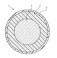
図1は、本発明の光ファイバの一例を示す概略断面図である。
光ファイバ1は、純シリカなどの石英系ガラスからなるコア層2の外周に紫外線硬化型樹脂などを硬化させてなるクラッド層3と、さら該クラッド層の外周に接するように形成されたインク層4とを有する。
例えば、該コア層2の外径は50μm〜100μm、該クラッド層3の厚さは12μm〜38μm(クラッド層3の外径125μm)、該インク層4の厚さは2μm〜10μm(インク層4の外径135μm)とすることができる。特に家庭用光複合USBケーブルやHDMIケーブルに用いる場合は、最小許容曲げ半径を小さくして取扱易くするために、該コア層2の外径を50μm〜90μm、該クラッド層3の厚さを17μm〜38μm(クラッド層3の外径125μm)、該インク層4の厚さを3μm〜8μm(インク層4の外径135μm)、として、比較的、細径にすることが好ましい。
Hereinafter, the optical fiber of the present invention will be described in detail with reference to FIG.
FIG. 1 is a schematic cross-sectional view showing an example of the optical fiber of the present invention.
The optical fiber 1 includes a clad layer 3 formed by curing an ultraviolet curable resin or the like on the outer periphery of a
For example, the outer diameter of the
また、前記コア層2と前記クラッド層3の界面の密着力は、1.5g/mm〜4.0g/mmである。密着力を当該値に規定することにより、光ファイバ1に外力がかかったときの剥離を抑制することができる。
即ち、光ファイバ1に外力、特に曲げ歪みが発生した場合、湾曲部においてクラッド層3の外側界面にはせん断応力が、内側界面には圧縮応力が生じクラッド層3をコア層2から剥がそうとする力が働く。そのため界面の密着力が弱いとクラッド層3が剥離する。特に、コア層2をカバーしていたクラッド層3の内側界面が剥がれると、当該部分のコア層2に他の部分よりも小径の曲げが発生する。そして緩衝材として働くはずのクラッド層3が剥離して空孔ができている為に、その部分での微小クラックの発生が急速に進行し、破断する可能性が高くなる。
従って、曲げ応力が加わったときのクラッド層3の剥離に伴う破断を抑制するには、界面の密着力を上記の値に規定する必要がある。
Moreover, the adhesive force at the interface between the
That is, when an external force, particularly a bending strain, is generated in the optical fiber 1, a shear stress is generated at the outer interface of the cladding layer 3 and a compressive stress is generated at the inner interface in the curved portion, so that the cladding layer 3 is peeled off from the
Therefore, in order to suppress breakage due to peeling of the clad layer 3 when bending stress is applied, it is necessary to define the adhesion force at the interface to the above value.
本発明の光ファイバ1のクラッド層3は硬化性樹脂組成物を硬化することにより形成される。
本発明の光ファイバ1のクラッド層3を形成するための硬化性樹脂組成物は、(A)フッ素原子含有ウレタン(メタ)アクリレート化合物、フッ素化されたポリエーテルを構造中に有する(メタ)アクリレート化合物、および(メタ)アクリレート化されたフッ素原子含有ビニル重合体から選ばれる少なくともいずれかの化合物(以下、フッ素系紫外線硬化型樹脂とも称する)と、(B)下記一般式(1)で表わされるアルコキシシランを0.2〜1wt%含有し、該クラッド層3中のフッ素含有量を20〜60wt%にできるものである。
一般式(1) Z−R−Si(X)3
(式中、Zは(メタ)アクリル基、メルカプト基またはエポキシ基を、Xは−OCH3または−OC2H5を、RはCnH2n(n=1,2,3,4,5)を表す。)
The clad layer 3 of the optical fiber 1 of the present invention is formed by curing a curable resin composition.
The curable resin composition for forming the cladding layer 3 of the optical fiber 1 of the present invention has (A) a fluorine atom-containing urethane (meth) acrylate compound and (meth) acrylate having a fluorinated polyether in the structure. A compound and at least one compound selected from a (meth) acrylated fluorine atom-containing vinyl polymer (hereinafter also referred to as a fluorine-based ultraviolet curable resin), and (B) represented by the following general formula (1) It contains 0.2 to 1 wt% of alkoxysilane, and the fluorine content in the cladding layer 3 can be set to 20 to 60 wt%.
General formula (1) Z—R—Si (X) 3
(In the formula, Z represents a (meth) acryl group, mercapto group or epoxy group, X represents —OCH 3 or —OC 2 H 5 , and R represents C n H 2n (n = 1, 2, 3, 4, 5 )
フッ素原子含有ウレタン(メタ)アクリレート化合物は、例えば、フッ素原子含有(メタ)アクリレート化合物とジイソシアネート化合物を反応させることにより得ることができる。また、ポリエーテルを分子構造中に有するフッ素原子含有(メタ)アクリレート化合物は、例えば、フッ素原子含有(メタ)アルコール化合物と、フッ素原子含有(メタ)アクリレート化合物またはアクリル酸とを反応させることによって得ることができる。 The fluorine atom-containing urethane (meth) acrylate compound can be obtained, for example, by reacting a fluorine atom-containing (meth) acrylate compound with a diisocyanate compound. The fluorine atom-containing (meth) acrylate compound having a polyether in the molecular structure is obtained by, for example, reacting a fluorine atom-containing (meth) alcohol compound with a fluorine atom-containing (meth) acrylate compound or acrylic acid. be able to.
また、該硬化性樹脂組成物には、上記一般式(1)で表わされるアルコキシシラン(シランカップリング剤)を含有することにより、前述に規定の密着力が実現できる。 Further, the curable resin composition contains the alkoxysilane (silane coupling agent) represented by the above general formula (1), whereby the prescribed adhesion can be realized.
また、該硬化性樹脂組成物には、上記の化合物以外に、例えばN−ビニルカプロラクタムなどの重合性不飽和モノマーや、下記光重合開始剤、あるいは各種添加剤など、光ファイバ1のクラッド層3の形成材料として通常用いられるものを使用することができる。 In addition to the above compounds, the curable resin composition includes, for example, a polymerizable unsaturated monomer such as N-vinylcaprolactam, the following photopolymerization initiator, or various additives, and the like. As the forming material, those usually used can be used.
更に、該硬化性樹脂組成物における上記アルコキシシラン以外の成分は、上記アルコキシシランを除く成分を混合した硬化性組成物を硬化させた際の屈折率が1.401〜1.450となるものを用いることが好ましい(ここでいう「アルコキシシラン以外の成分」とは、クラッド層3の形成に実質的に関与する、重合性化合物、光重合開始剤、あるいはフッ素系紫外線硬化型樹脂等を意味する(単に溶解させる等のみに添加される揮発性溶媒等は含まない))。この範囲の屈折率の硬化性樹脂組成物で優れたファイバ強度と伝送特性を両立することが確認されている(具体的には1.401、1.413、1.430、1.450)。屈折率が1.450を超えるとコア層2との屈折率の差が小さく光信号を伝搬するに適さない。また、アルコキシシランとクラッド層3を構成する主材料となるフッ素系紫外線硬化型樹脂等の相溶性が低下すると、クラッド層3を構成する樹脂が白濁してしまい、伝送特性の低下の原因となる。本硬化性樹脂組成物においては、クラッド層3のアルコキシシラン以外の成分を混合した硬化性組成物の屈折率を上記数値範囲とすることで、クラッド層3を構成する主材料となるフッ素系紫外線樹脂等と上記アルコキシシランとの相溶性を担保している。
Furthermore, the components other than the alkoxysilane in the curable resin composition have a refractive index of 1.401 to 1.450 when the curable composition obtained by mixing the components excluding the alkoxysilane is cured. It is preferable to use (the “component other than alkoxysilane” here means a polymerizable compound, a photopolymerization initiator, or a fluorine-based ultraviolet curable resin that substantially participates in the formation of the clad layer 3. (It does not include volatile solvents that are added only to dissolve them). It has been confirmed that a curable resin composition having a refractive index in this range achieves both excellent fiber strength and transmission characteristics (specifically, 1.401, 1.413, 1.430, 1.450). If the refractive index exceeds 1.450, the difference in refractive index from the
硬化性樹脂組成物において、上記一般式(I)で表されるアルコキシシランは、硬化性樹脂組成物中に0.2〜1wt%含有される。クラッド層3を形成する硬化性樹脂組成物において、一般式(I)で表されるアルコキシシランを上記数値範囲で含有させることにより、硬化性樹脂組成物の硬化前の初期1秒間における動的接触角の低下量を大きくでき、即ち、硬化性樹脂組成物とコア層2とが短時間でなじむため、形成されるクラッド層3とコア層2との密着力を格段に向上させることができる。上記一般式(I)で表されるアルコキシシランの添加量が0.2wt%未満であると密着力向上効果が得られず、一方、添加量が1wt%を超えると、ファイバ強度は向上するものの、一般式(I)で表されるアルコキシシランとフッ素系紫外線硬化型樹脂の相溶性が低下し、樹脂が白濁することにより伝送特性が低下する懸念がある。
In the curable resin composition, the alkoxysilane represented by the general formula (I) is contained in the curable resin composition in an amount of 0.2 to 1 wt%. In the curable resin composition for forming the clad layer 3, by containing the alkoxysilane represented by the general formula (I) in the above numerical range, the dynamic contact in the initial 1 second before the curable resin composition is cured. The amount of decrease in corners can be increased, that is, the curable resin composition and the
該硬化性樹脂組成物における光重合開始剤としては公知のどのような光重合開始剤を用いても構わないが、配合した後の貯蔵安定性のよいことが要求される。このような光重合開始剤の具体例としては、例えば、2−ヒドロキシ−2−メチル−1−フェニルプロパン−1−オン等を挙げることができる。 Any known photopolymerization initiator may be used as the photopolymerization initiator in the curable resin composition, but it is required to have good storage stability after blending. Specific examples of such a photopolymerization initiator include 2-hydroxy-2-methyl-1-phenylpropan-1-one.
本発明の光ファイバ1において、上記のような硬化性樹脂組成物を硬化することにより形成されたクラッド層3は、フッ素含有量が20〜60wt%である。
クラッド層3中のフッ素含有量が20wt%未満であると、クラッド層3とインク層4の剥離性が低下し、インク層4が除去し難くくなる。クラッド層3中のフッ素含有量が60wt%を超えると、フッ素系紫外線硬化型樹脂と前記アルコキシシランとの相溶性が悪くなり、クラッド層3が白濁し、光信号が伝播できなくなり、伝送損失が大きくなる。
また、本発明の光ファイバにおいて、クラッド層3とインク層4との密着力は0.1〜0.4g/mmであることが好ましい。
In the optical fiber 1 of the present invention, the clad layer 3 formed by curing the curable resin composition as described above has a fluorine content of 20 to 60 wt%.
When the fluorine content in the clad layer 3 is less than 20 wt%, the peelability between the clad layer 3 and the ink layer 4 decreases, and the ink layer 4 becomes difficult to remove. When the fluorine content in the clad layer 3 exceeds 60 wt%, the compatibility between the fluorine-based ultraviolet curable resin and the alkoxysilane is deteriorated, the clad layer 3 becomes clouded, the optical signal cannot be propagated, and transmission loss is reduced. growing.
In the optical fiber of the present invention, the adhesion between the clad layer 3 and the ink layer 4 is preferably 0.1 to 0.4 g / mm.
本発明の光ファイバ1のインク層4は、前記クラッド層3の外周に接するように形成される。
前記インク層4は、着色顔料と紫外線硬化型ウレタン(メタ)アクリレート化合物とを含む組成物より形成される。
該紫外線硬化型ウレタン(メタ)アクリレート化合物としては、特に限定されないが、例えば、
(a)ビスフェノールA又はビスフェノールFのアルキレンオキサイド付加物
(b)ジイソシアネート及び
(c)ヒドロキシル基含有(メタ)アクリレート化合物
を反応させてなるウレタン(メタ)アクリレートが好ましい。
The ink layer 4 of the optical fiber 1 of the present invention is formed so as to be in contact with the outer periphery of the cladding layer 3.
The ink layer 4 is formed of a composition containing a color pigment and an ultraviolet curable urethane (meth) acrylate compound.
The ultraviolet curable urethane (meth) acrylate compound is not particularly limited.
Urethane (meth) acrylate obtained by reacting (a) bisphenol A or bisphenol F alkylene oxide adduct (b) diisocyanate and (c) hydroxyl group-containing (meth) acrylate compound is preferred.
上記(a)成分のビスフェノールA(2,2−ビス(4′−ヒドロキシフェニル)プロパン)又はビスフェノールF(ビス(4−ヒドロキシフェニル)メタン)のアルキレンオキサイド付加物としては、例えばエチレンオキサイド、プロピレンオキサイド、ブチレンオキサイド等の付加物が挙げられる。これらのアルキレンオキサイドの付加モル数としては、ビスフェノールA又はビスフェノールF1モル当り1〜15モルが好ましい。
(b)成分のジイソシアネートとしては、例えばトリレンジイソシアネート(TDI)、ヘキサメチレンジイソシアネート(HDI)、ジフェニルメタンジイソシアネート(MDI)、水添ジフェニルメタンジイソシアネート(水添MDI)、イソフォロンジイソシアネート(IPDI)等が挙げられる。
(c)成分のヒドロキシル基含有(メタ)アクリレート化合物としては、例えば2−ヒドロキシエチル(メタ)アクリレート、2−ヒドロキシプロピル(メタ)アクリレート等が挙げられる。これらのうち、得られるインク層形成用組成物の硬化速度向上の点から、特にメタアクリレート化合物よりもアクリレート化合物が好ましい。
Examples of the alkylene oxide adduct of bisphenol A (2,2-bis (4′-hydroxyphenyl) propane) or bisphenol F (bis (4-hydroxyphenyl) methane) as component (a) include ethylene oxide and propylene oxide. And adducts such as butylene oxide. The added mole number of these alkylene oxides is preferably 1 to 15 moles per mole of bisphenol A or bisphenol F.
Examples of component (b) diisocyanate include tolylene diisocyanate (TDI), hexamethylene diisocyanate (HDI), diphenylmethane diisocyanate (MDI), hydrogenated diphenylmethane diisocyanate (hydrogenated MDI), isophorone diisocyanate (IPDI), and the like. .
Examples of the hydroxyl group-containing (meth) acrylate compound (c) include 2-hydroxyethyl (meth) acrylate and 2-hydroxypropyl (meth) acrylate. Of these, acrylate compounds are particularly preferable to methacrylate compounds from the viewpoint of improving the curing rate of the resulting ink layer forming composition.
これら(a)〜(c)を反応させる方法としては、例えば触媒の存在下、通常20〜60℃で(1)(b)成分、(a)成分、(c)成分又は(b)成分、(c)成分、(a)成分の順序で添加させる方法、(2)(a)、(b)両成分を反応させた後(c)成分を添加する方法、(3)(a)、(b)、(c)各成分を同時に反応させる方法等が挙げられる。触媒としては、例えばトリエチルアミン等の3級アミン化合物、ジブチル錫ジラウレート等の有機錫化合物等が挙げられる。このようにして得られるウレタン(メタ)アクリレートは、例えば下記一般式(II)で表わされるものである。 As a method for reacting these (a) to (c), for example, in the presence of a catalyst, usually at 20 to 60 ° C., (1) (b) component, (a) component, (c) component or (b) component, (C) component, a method of adding component (a) in this order, (2) (a), (b) a method of adding component (c) after reacting both components, (3) (a), ( Examples thereof include a method of reacting each component b) and (c) simultaneously. Examples of the catalyst include tertiary amine compounds such as triethylamine, and organic tin compounds such as dibutyltin dilaurate. The urethane (meth) acrylate thus obtained is represented, for example, by the following general formula (II).

(式中、R1及びR5は、それぞれ水素原子又はメチル基を示し、R2は炭素数1〜6のアルキレン基を示し、R3はジイソシアネート残基を示し、R4は水素原子、メチル基又はエチル基を示し、lは1〜10、m及びnは1〜30の整数を示す) (In the formula, R 1 and R 5 each represent a hydrogen atom or a methyl group, R 2 represents an alkylene group having 1 to 6 carbon atoms, R 3 represents a diisocyanate residue, and R 4 represents a hydrogen atom or methyl. A group or an ethyl group, l is 1 to 10, m and n are integers of 1 to 30)
一般式(II)中、R2で示される炭素数1〜6のアルキレン基としては、例えばメチレン基、エチレン基、プロピレン基、ブチレン基、ペンタメチレン基、ヘキサメチレン基などが挙げられる。また、lは1〜10の整数であるが、特に1〜4が好ましく、m及びnは1〜30の整数であるが特に1〜15が好ましい。
一般式(II)で表わされるウレタン(メタ)アクリレートは、エチレンオキサイド(又はプロピレンオキサイド若しくはブチレンオキサイド)変性ビスフェノールF(又はA)ウレタン(メタ)アクリレートであり、これらの市販品としては、例えばNKエステルU−1301A(新中村化学(株)製)、NKエステルU−701A(新中村化学(株)製)、NKエステルU−401A(新中村化学(株)製)、NKエステルU−601BA(新中村化学(株)製)、NKエステルU−1001BA(新中村化学(株)製)等が挙げられる。これらウレタン(メタ)アクリレートは、インク層形成用組成物中に通常5〜80重量%(以下、単に「%」で示す)。好ましくは5〜70%配合することができる。
Examples of the alkylene group having 1 to 6 carbon atoms represented by R 2 in the general formula (II) include a methylene group, an ethylene group, a propylene group, a butylene group, a pentamethylene group, and a hexamethylene group. L is an integer of 1 to 10, particularly preferably 1 to 4, and m and n are integers of 1 to 30, but 1 to 15 is particularly preferable.
The urethane (meth) acrylate represented by the general formula (II) is ethylene oxide (or propylene oxide or butylene oxide) modified bisphenol F (or A) urethane (meth) acrylate, and examples of these commercially available products include NK ester. U-1301A (made by Shin-Nakamura Chemical Co., Ltd.), NK ester U-701A (made by Shin-Nakamura Chemical Co., Ltd.), NK ester U-401A (made by Shin-Nakamura Chemical Co., Ltd.), NK ester U-601BA (new) Nakamura Chemical Co., Ltd.), NK ester U-1001BA (manufactured by Shin-Nakamura Chemical Co., Ltd.) and the like. These urethane (meth) acrylates are usually 5 to 80% by weight (hereinafter simply indicated as “%”) in the ink layer forming composition. Preferably 5 to 70% can be blended.
前記ウレタン(メタ)アクリレート以外に、各種の紫外線硬化性樹脂を併用することができる。かかる紫外線硬化性樹脂としては、例えば各種エポキシアクリレート樹脂、ポリエステルアクリレート樹脂等のアクリレートオリゴマーと、ネオペンチルグリコールアクリレート、N−ビニルピロリドン、ペンタエリスリトールトリアクリレート等のエチレン性不飽和基を有する単官能及び多官能モノマーから成るもの等が挙げられる。これらの樹脂は、インク層形成用組成物中に通常0〜90%、好ましくは20〜80%配合することができる。 In addition to the urethane (meth) acrylate, various ultraviolet curable resins can be used in combination. Examples of the ultraviolet curable resin include monofunctional and polyfunctional monomers having an ethylenically unsaturated group such as acrylate oligomers such as various epoxy acrylate resins and polyester acrylate resins, and neopentyl glycol acrylate, N-vinylpyrrolidone, and pentaerythritol triacrylate. The thing which consists of a functional monomer is mentioned. These resins can be blended in the ink layer forming composition usually in an amount of 0 to 90%, preferably 20 to 80%.
また、インク層形成用組成物中には、着色顔料、光重合開始剤等を配合する。
着色顔料としては、例えばカーボンブラック、酸化チタン、亜鉛華、不溶性アゾ顔料、縮合アゾ顔料、多環式顔料等が挙げられる。これら着色顔料を、インク層形成用組成物中に通常0.1〜50%、好ましくは2〜10%配合することができる。
Further, a coloring pigment, a photopolymerization initiator, and the like are blended in the ink layer forming composition.
Examples of the color pigment include carbon black, titanium oxide, zinc white, insoluble azo pigment, condensed azo pigment, and polycyclic pigment. These color pigments can be generally blended in the ink layer forming composition in an amount of 0.1 to 50%, preferably 2 to 10%.
光重合開始剤としては、例えばベンゾフェノン、ベンゾイン、ベンゾインイソブチルエーテル、ベンジル、ベンゾインエチルエーテル、2,2−ジメトキシ−2−フェニルアセトフェノン、キサントン、フルオレノン、4−クロロベンゾフェノン、トリフェニルアミン、カルバゾール、3−メチルアセトフェノン、4,4′−ジメトキシベンゾフェノン、4,4′−ジアミノベンゾフェノン、ミヒラーケトン、ベンゾインプロピルエーテル、アセトフェノンジエチルケタール、ベンゾインエチルエーテル、1−ヒドロキシシクロヘキシルフェニルケトン、4′−イソプロピル−2−ヒドロキシ−2−メチル−プロピオフェノン、2−ヒドロキシ−2−メチル−プロピオフェノン、α、α′−ジクロロ−4−フェノキシアセトフェノン、ベンジルジメチルケタール、2,2−ジエトキシアセトフェノン、クロロチオキサントン、2−イソプロピルチオキサントン、ジエチルチオキサントン、3,3−ジメチル−4−メトキシベンゾフェノン、2−メチル−1−〔4−(メチルチオ)フェニル〕−2−モルホリノプロパノン、α−ヒドロキシシクロヘキシルフェニルケトン、ユペクリルP36(UCB社製高分子量化ベンゾフェノン)、2,4,6−トリメチルベンゾイルジフェニルホスフィンオキシド等のラジカル系光重合開始剤、2,5−ジエトキシ−4−(p−トリルメルカプト)ベンゼンジアゾニウムPF6 −、2,4,6−トリクロロベンゼンジアゾニウムPF6 −、4−ジメチルアミノナフタレンジアゾニウムPF6 −、シクロペンタジエニルフェロセニウムPF6 −等のイオン系光重合開始剤等が挙げられる。これら光重合開始剤は、インク層形成用組成物中に通常0.5〜20%、好ましくは3〜10%配合することができる。 Examples of the photopolymerization initiator include benzophenone, benzoin, benzoin isobutyl ether, benzyl, benzoin ethyl ether, 2,2-dimethoxy-2-phenylacetophenone, xanthone, fluorenone, 4-chlorobenzophenone, triphenylamine, carbazole, 3- Methyl acetophenone, 4,4'-dimethoxybenzophenone, 4,4'-diaminobenzophenone, Michler's ketone, benzoin propyl ether, acetophenone diethyl ketal, benzoin ethyl ether, 1-hydroxycyclohexyl phenyl ketone, 4'-isopropyl-2-hydroxy-2 -Methyl-propiophenone, 2-hydroxy-2-methyl-propiophenone, α, α'-dichloro-4-phenoxyacetophenone, benzyl Dimethyl ketal, 2,2-diethoxyacetophenone, chlorothioxanthone, 2-isopropylthioxanthone, diethylthioxanthone, 3,3-dimethyl-4-methoxybenzophenone, 2-methyl-1- [4- (methylthio) phenyl] -2- Radical photopolymerization initiators such as morpholinopropanone, α-hydroxycyclohexyl phenyl ketone, Upecyl P36 (high molecular weight benzophenone manufactured by UCB), 2,4,6-trimethylbenzoyldiphenylphosphine oxide, 2,5-diethoxy-4 - (p-tolyl-mercapto) benzene diazonium PF 6 -, 2,4,6-trichlorobenzene diazonium PF 6 -, 4-dimethylamino-naphthalene diazonium PF 6 -, cyclopentadienyl ferrocenium PF 6 - And ionic photopolymerization initiators. These photopolymerization initiators can be normally blended in the ink layer forming composition in an amount of 0.5 to 20%, preferably 3 to 10%.
さらに、必要に応じて光増感剤、保存安定剤、レベリング剤又は紫外線吸収剤であるn−ブチルアミン、トリ−n−ブチルホスフィン、S−ベンジルイソチウロニウム−R−トルエンスルホネート、トリエチルアミン、ジエチルアミノエチル(メタ)アクリレート、ハイドロキノンモノメチルエーテル、p−ジメチルアミノ安息香酸エチルエステル、2,6−ジ−t−ブチル−p−メチルフェノール等を配合することができる。
上記各成分を常法により混合して製造することができ、これを光ファイバ1のクラッド層3に塗布後、高圧水銀灯、メタルハライドランプ等により紫外線を照射して硬化せしめれば光ファイバ1にインク層4を形成することができる。
Further, n-butylamine, tri-n-butylphosphine, S-benzylisothuronium-R-toluenesulfonate, triethylamine, diethylaminoethyl which is a photosensitizer, a storage stabilizer, a leveling agent or an ultraviolet absorber as necessary. (Meth) acrylate, hydroquinone monomethyl ether, p-dimethylaminobenzoic acid ethyl ester, 2,6-di-t-butyl-p-methylphenol and the like can be blended.
Each of the above components can be mixed by a conventional method to be manufactured. After coating the clad layer 3 of the optical fiber 1, the ink is applied to the optical fiber 1 by curing it by irradiating ultraviolet rays with a high pressure mercury lamp, a metal halide lamp or the like. Layer 4 can be formed.
コア層とクラッド層との密着力は下記のようにして測定できる。
板ガラス(大型スライドガラス、76×52mm)にクラッド層を形成する硬化性組成物を厚さ10μmになるようにスピンコーティングし、100mJ/cm2のUV光を照射して硬化して板ガラス上に樹脂フィルムを形成する。
常温で一昼夜以上放置後、樹脂フィルムに切込みを入れ、樹脂フィルムを1cm剥がす。樹脂フィルム端を引張試験機のチャックで挟み90°剥離強度を測定する。測定は、50Nのロードセルを使用し、引張強度100mm/minとする。剥離する時の力をサンプル幅で割った値を密着力とする。
The adhesion between the core layer and the clad layer can be measured as follows.
A curable composition for forming a clad layer is spin-coated on a plate glass (large slide glass, 76 × 52 mm) so as to have a thickness of 10 μm, and cured by irradiating with 100 mJ / cm 2 of UV light to be a resin on the plate glass. Form a film.
After leaving at room temperature for a day or more, cut into the resin film and peel off the resin film by 1 cm. The 90 ° peel strength is measured by sandwiching the end of the resin film with a chuck of a tensile tester. The measurement uses a 50N load cell and the tensile strength is 100 mm / min. The value obtained by dividing the force at the time of peeling by the sample width is defined as the adhesion force.
クラッド層とインク層との密着力は下記のようにして測定できる。
クラッド層を形成する硬化性組成物を厚さ130μmになるように硬化して樹脂フィルムを形成する。 このフィルム上にインク層を厚さ10μmになるようにスピンコーティングし、20mJ/cm2のUV光を照射して硬化してクラッド層の樹脂フィルム上にインク層の樹脂フィルムを形成する。
常温で一昼夜以上放置後、インク層の樹脂フィルムを1cm剥がす。インク層の樹脂フィルム端を引張試験機のチャックで挟み90°剥離強度を測定する。測定は、10Nのロードセルを使用し、引張強度50mm/minとする。剥離する時の力をサンプル幅で割った値を密着力とする。
The adhesion between the clad layer and the ink layer can be measured as follows.
A curable composition for forming the cladding layer is cured to a thickness of 130 μm to form a resin film. An ink layer is spin-coated on this film so as to have a thickness of 10 μm, and cured by irradiating with 20 mJ / cm 2 of UV light to form a resin film of the ink layer on the resin film of the clad layer.
After leaving at room temperature for a day or more, 1 cm of the resin film of the ink layer is peeled off. The 90 ° peel strength is measured by sandwiching the resin film end of the ink layer with a chuck of a tensile tester. The measurement uses a 10N load cell and the tensile strength is 50 mm / min. The value obtained by dividing the force at the time of peeling by the sample width is defined as the adhesion force.
以下、本発明に係る実施例及び比較例を用いた評価試験の結果を示し、本発明をさらに詳細に説明する。なお、本発明はこれら実施例に限定されるものではない。 Hereinafter, the results of evaluation tests using examples and comparative examples according to the present invention will be shown, and the present invention will be described in more detail. The present invention is not limited to these examples.
[光ファイバの作製]
石英系ガラスからなる外径80μmのコア層の外周に下記組成のクラッド層形成用硬化性樹脂組成物によりクラッド層を外径125μmになるように形成し、該クラッド層の外周に下記組成のインク層形成用組成物によりインク層を外径135μmになるように形成し、光ファイバ(実施例1〜2、比較例1〜2)を作製した。
[Fabrication of optical fiber]
A clad layer is formed on the outer periphery of a core layer made of quartz glass having an outer diameter of 80 μm with a curable resin composition for forming a clad layer having the following composition so that the outer diameter is 125 μm. An ink layer was formed to have an outer diameter of 135 μm with the layer forming composition, and optical fibers (Examples 1 and 2 and Comparative Examples 1 and 2) were produced.
〔クラッド層形成用硬化性樹脂組成物〕
フッ素原子含有ウレタン(メタ)アクリレート化合物 30重量%
3-アクリロキシプロピルメチルトリメトキシシラン 0.36重量%
光重合開始剤 LucirinTPO(BASF社製) 2重量%
アクリル酸 3.6重量%
多官能アクリル系モノマー(ペンタエリスリトールテトラメタクリレート)
40重量%
フッ素系モノマー(ビスコート17F;2−パーフルオロオクチルエチル(メタ)アクリレート,大阪有機化学工業社製) 25重量%
[Curable layer forming curable resin composition]
Fluorine atom-containing urethane (meth) acrylate compound 30% by weight
3-acryloxypropylmethyltrimethoxysilane 0.36% by weight
Photopolymerization initiator LucirinTPO (BASF) 2% by weight
Acrylic acid 3.6% by weight
Multifunctional acrylic monomer (pentaerythritol tetramethacrylate)
40% by weight
Fluorine monomer (Biscoat 17F; 2-perfluorooctylethyl (meth) acrylate, manufactured by Osaka Organic Chemical Industry Co., Ltd.) 25% by weight
〔インク層形成用組成物〕
ウレタンアクリレート(新中村化学(株)製 NKエステルU-1301A) 60 重量部
ネオペンチルグリコールジアクリレート(日本化薬(株)製 NPGOA) 40 重量部
光重合開始剤(チバガイギー社製 イルガキュア907) 5 重量部
青色顔料(大日精化製 フタロシアニンブルー2CA104) 6 重量部
[Ink layer forming composition]
Urethane acrylate (NK Nakano U-1301A manufactured by Shin-Nakamura Chemical Co., Ltd.) 60 parts by weight Neopentyl glycol diacrylate (NPGOA manufactured by Nippon Kayaku Co., Ltd.) 40 parts by weight Photopolymerization initiator (Irgacure 907 manufactured by Ciba Geigy) 5 parts by weight Part Blue Pigment (Daiichi Seikagaku Phthalocyanine Blue 2CA104) 6 parts by weight
[光ファイバの評価]
作製した光ファイバについてインク層の除去性と光信号の伝播性の評価を行った。インク層の除去性と光信号の伝播性の評価方法は以下の通りであり。結果を下記表1に示す。
[Evaluation of optical fiber]
The fabricated optical fiber was evaluated for ink layer removal and optical signal propagation. The evaluation method of the removal property of the ink layer and the propagation property of the optical signal is as follows. The results are shown in Table 1 below.
〔インク層の除去性〕
評価方法と判断基準
光ファイバ除去具(通常の125マイクロメートルのガラスファイバ用、ここではRIPLEY Co.製のFO103−S)を使用しN=20でインク層のみの除去試験を行った。除去時は、除去具を手前側に約45°傾けた状態で除去し、アルコールで軽くファイバ表面を洗浄した後、光ファイバクラッド樹脂層表面を観察した。このとき、傷や樹脂剥がれ、インク残り等の異常が無いかを確認した。N=20全数で異常が無かった場合に合格(○の判定)、1つでも異常が発見された場合には不合格(×の判定)とした。
[Removability of ink layer]
Evaluation Method and Judgment Criteria An optical fiber removal tool (for ordinary 125 micrometer glass fiber, here FO103-S manufactured by RIPLEY Co.) was used, and a removal test of only the ink layer was performed at N = 20. At the time of removal, the removal tool was removed in a state tilted by about 45 ° toward the front side, the surface of the fiber was lightly washed with alcohol, and then the surface of the optical fiber clad resin layer was observed. At this time, it was confirmed whether there were any abnormalities such as scratches, peeling of the resin, and remaining ink. If no abnormality was found in all N = 20, it was judged to be acceptable (good judgment), and if any abnormality was found, it was judged to be unacceptable (good judgment).
〔光ファイバの伝送損失〕
評価方法と判断基準
伝送損失は、カットバック法で測定した。コア径65マイクロメートル、クラッド径125マイクロメートルの市販のGIファイバ(NA=0.29)のファイバの片端側断面と、被測定HPCFの片端側断面をつき合わせる。GIファイバのもう片端から光源からの光を入射し、被測定ファイバHPCFのもう片端は光強度測定機に接続する。光源光は、白色光をモノクロメーターに通して波長を掃引することで、HPCFからの出射光強度スペクトル(P’(λ))を測定する。続いて、HPCFのGIファイバとの接続端から1mのところでファイバを切断し、切断した端部を光検出器に接続して同様に出射光の強度スペクトルを測定する(P(λ))。P’(λ)とP(λ)の差を被測定光ファイバの距離で除して伝送損失スペクトルを測定し、波長850nmの伝送損失を測定した。850nmの伝送損失が15dB/kmよりも大きい伝送損失もしくは異常なスペクトル成分があった場合に不合格(×の判定)、15dB/km以下(○の判定)かつスペクトルに異常なき場合に合格とした。
[Optical fiber transmission loss]
Evaluation Method and Judgment Criteria Transmission loss was measured by the cutback method. A cross section of one end of a commercially available GI fiber (NA = 0.29) having a core diameter of 65 micrometers and a clad diameter of 125 micrometers is matched with a cross section of one end of the HPCF to be measured. Light from the light source is incident from the other end of the GI fiber, and the other end of the fiber to be measured HPCF is connected to a light intensity measuring machine. As the light source light, white light is passed through a monochromator and the wavelength is swept to measure the intensity spectrum (P ′ (λ)) emitted from the HPCF. Subsequently, the fiber is cut at 1 m from the connection end with the HPCF GI fiber, the cut end is connected to a photodetector, and the intensity spectrum of the emitted light is similarly measured (P (λ)). The transmission loss spectrum was measured by dividing the difference between P ′ (λ) and P (λ) by the distance of the optical fiber to be measured, and the transmission loss at a wavelength of 850 nm was measured. Fail when the transmission loss at 850 nm is greater than 15 dB / km or abnormal spectral components (decision x), and pass if it is 15 dB / km or less (circle judgment) and the spectrum is not abnormal .
上記結果より、クラッド層中のフッ素原子濃度を20〜60wt%の範囲とすることによってインク層の除去性と光信号の伝播性が両立できることが確認された。 From the above results, it was confirmed that both the removability of the ink layer and the propagation property of the optical signal can be achieved by setting the fluorine atom concentration in the clad layer in the range of 20 to 60 wt%.
1 光ファイバ、2 コア層、3 クラッド層、4 インク層 1 optical fiber, 2 core layer, 3 cladding layer, 4 ink layer
Claims (2)
前記コア層と前記クラッド層との密着力が1.5g/mm〜4.0g/mmであり、
前記インク層は着色顔料と紫外線硬化型ウレタン(メタ)アクリレート化合物とを含む組成物より形成され、
前記クラッド層を形成するための硬化性樹脂組成物は、フッ素原子含有ウレタン(メタ)アクリレート化合物、フッ素化されたポリエーテルを構造中に有する(メタ)アクリレート化合物、および(メタ)アクリレート化されたフッ素原子含有ビニル重合体から選ばれる少なくともいずれかの化合物と、下記一般式(1)で表わされるアルコキシシランを0.2〜1wt%含有し、
前記クラッド層中のフッ素含有量が20〜60wt%であり、
前記インク層は最外層であり、
前記クラッド層と前記インク層との密着力が0.1g/mm〜0.4g/mmである光ファイバ。
一般式(1) Z−R−Si(X) 3
(式中、Zは(メタ)アクリル基、メルカプト基またはエポキシ基を、Xは−OCH 3 または−OC 2 H 5 を、RはC n H 2n (n=2,3,4,5)を表す。) An optical fiber provided with a cladding layer formed by curing a curable resin composition on an outer periphery of a core layer made of quartz glass, and an ink layer formed so as to be in contact with the outer periphery of the cladding layer. ,
Ri adhesion is 1.5g / mm~4.0g / mm der between the cladding layer and the core layer,
The ink layer is formed from a composition containing a color pigment and an ultraviolet curable urethane (meth) acrylate compound,
The curable resin composition for forming the cladding layer is a fluorine atom-containing urethane (meth) acrylate compound, a (meth) acrylate compound having a fluorinated polyether in the structure, and (meth) acrylated Containing at least one compound selected from fluorine atom-containing vinyl polymers and 0.2 to 1 wt% of alkoxysilane represented by the following general formula (1),
The fluorine content in the cladding layer is 20-60 wt%,
The ink layer is the outermost layer;
An optical fiber having an adhesion force between the clad layer and the ink layer of 0.1 g / mm to 0.4 g / mm .
General formula (1) Z—R—Si (X) 3
(In the formula, Z represents a (meth) acryl group, mercapto group or epoxy group, X represents —OCH 3 or —OC 2 H 5 , and R represents C n H 2n (n = 2, 3, 4, 5). Represents.)
Priority Applications (3)
| Application Number | Priority Date | Filing Date | Title |
|---|---|---|---|
| JP2012091829A JP5605389B2 (en) | 2012-04-13 | 2012-04-13 | Optical fiber |
| US13/861,649 US9229159B2 (en) | 2012-04-13 | 2013-04-12 | Optical fiber |
| CN2013101273815A CN103376500A (en) | 2012-04-13 | 2013-04-12 | Fiber |
Applications Claiming Priority (1)
| Application Number | Priority Date | Filing Date | Title |
|---|---|---|---|
| JP2012091829A JP5605389B2 (en) | 2012-04-13 | 2012-04-13 | Optical fiber |
Publications (3)
| Publication Number | Publication Date |
|---|---|
| JP2013221978A JP2013221978A (en) | 2013-10-28 |
| JP2013221978A5 JP2013221978A5 (en) | 2013-12-26 |
| JP5605389B2 true JP5605389B2 (en) | 2014-10-15 |
Family
ID=49461886
Family Applications (1)
| Application Number | Title | Priority Date | Filing Date |
|---|---|---|---|
| JP2012091829A Expired - Fee Related JP5605389B2 (en) | 2012-04-13 | 2012-04-13 | Optical fiber |
Country Status (3)
| Country | Link |
|---|---|
| US (1) | US9229159B2 (en) |
| JP (1) | JP5605389B2 (en) |
| CN (1) | CN103376500A (en) |
Families Citing this family (7)
| Publication number | Priority date | Publication date | Assignee | Title |
|---|---|---|---|---|
| JP6369215B2 (en) * | 2014-08-13 | 2018-08-08 | 住友電気工業株式会社 | Optical fiber core and manufacturing method thereof |
| JP6428101B2 (en) * | 2014-09-26 | 2018-11-28 | 住友電気工業株式会社 | Optical fiber core and optical fiber ribbon |
| US10241262B2 (en) * | 2015-10-14 | 2019-03-26 | Sumitomo Electric Industries, Ltd. | Optical fiber |
| US9874684B2 (en) * | 2015-11-09 | 2018-01-23 | Sumitomo Electric Industries, Ltd. | Optical fiber |
| KR101858732B1 (en) * | 2016-09-13 | 2018-05-16 | 한국광기술원 | optical transmission apparatus of medical endoscope |
| NL2020318B1 (en) * | 2017-12-07 | 2019-07-31 | Corning Inc | Improved method of applying an ink layer onto an optical fibre |
| JPWO2022168476A1 (en) * | 2021-02-04 | 2022-08-11 |
Family Cites Families (31)
| Publication number | Priority date | Publication date | Assignee | Title |
|---|---|---|---|---|
| US4290668A (en) * | 1978-11-29 | 1981-09-22 | Raychem Corporation | Fiber optic waveguide termination and method of forming same |
| US4317616A (en) * | 1979-10-09 | 1982-03-02 | Raychem Corporation | Fluorosiloxane optical cladding |
| US4583851A (en) * | 1981-07-13 | 1986-04-22 | Northern Telecom Limited | Method and apparatus for monitoring optical fiber concentricity |
| CA1315430C (en) * | 1987-03-12 | 1993-03-30 | Andrew Garton | Fortifiers for anhydride-cured epoxy resins |
| JPS6424203A (en) * | 1987-07-20 | 1989-01-26 | Sumitomo Electric Industries | Polymer-clad optical fiber and clad material |
| JPH03107105A (en) * | 1989-09-20 | 1991-05-07 | Toray Ind Inc | Optical fiber clad material |
| JPH03163505A (en) * | 1989-11-22 | 1991-07-15 | Furukawa Electric Co Ltd:The | Coated optical fiber |
| WO1996003609A1 (en) * | 1994-07-22 | 1996-02-08 | Optical Polymer Research, Inc. | Curable, inter-polymer optical fiber cladding compositions |
| US5740295A (en) * | 1994-11-02 | 1998-04-14 | Lucent Technologies Inc. | Low fiber count optical cable |
| JP2000056191A (en) * | 1998-08-10 | 2000-02-25 | Sumitomo Electric Ind Ltd | Coated optical fiber |
| WO2002006175A1 (en) * | 2000-06-22 | 2002-01-24 | Pirelli Cavi E Sistemi S.P.A. | Colored optical fiber and optical fiber ribbon assembly containing said fiber |
| JP2004012679A (en) * | 2002-06-05 | 2004-01-15 | Fujikura Ltd | Visible small-diameter optical fiber |
| JP2004021118A (en) * | 2002-06-19 | 2004-01-22 | Sumitomo Electric Ind Ltd | Plastic clad optical fiber |
| US20040037521A1 (en) * | 2002-08-22 | 2004-02-26 | Shunhe Xiong | Methods and apparatus for coloring optical fibers during draw |
| KR100500191B1 (en) * | 2002-09-10 | 2005-07-14 | 에스에스씨피 주식회사 | Uv-curable resin composition for cladding layer of optical fiber |
| JP2004198506A (en) * | 2002-12-16 | 2004-07-15 | Fujikura Ltd | Thin film optical fiber, thin film coated optical fiber, and connector connecting part |
| JP2004309648A (en) * | 2003-04-03 | 2004-11-04 | Sumitomo Electric Ind Ltd | Method for manufacturing fiberoptic cable |
| KR100506200B1 (en) * | 2003-05-07 | 2005-08-05 | 삼성전자주식회사 | Double-coated optical fiber |
| KR100579007B1 (en) * | 2003-08-13 | 2006-05-12 | 주식회사 루밴틱스 | Photocurable and antistatic resin composition for optical fiber coating |
| ATE451405T1 (en) * | 2004-10-15 | 2009-12-15 | Dsm Ip Assets Bv | RADIATION CURED COATING COMPOSITION |
| JP2006201469A (en) * | 2005-01-20 | 2006-08-03 | Sumitomo Electric Ind Ltd | Plastic clad optical fiber |
| US7323535B2 (en) * | 2005-05-20 | 2008-01-29 | General Electric Company | Transparent compositions, methods for the preparation thereof, and articles derived therefrom |
| JP2007017549A (en) * | 2005-07-05 | 2007-01-25 | Sumitomo Electric Ind Ltd | Overcoated core wire |
| WO2008118488A1 (en) * | 2007-03-26 | 2008-10-02 | Egene, Inc. | Capillary electrophoresis using clear coated capillary tubes |
| WO2009096557A1 (en) * | 2008-01-30 | 2009-08-06 | Asahi Glass Co., Ltd. | Optical fiber preform used for energy transmission or ultraviolet light transmission and method of manufacturing the optical fiber preform |
| JP2009198706A (en) * | 2008-02-20 | 2009-09-03 | Sumitomo Electric Ind Ltd | Polymer clad coated optical fiber |
| ES2431014T3 (en) * | 2009-03-31 | 2013-11-22 | Toray Industries, Inc. | Plastic fiber optic and plastic fiber optic code |
| JP2011107217A (en) * | 2009-11-12 | 2011-06-02 | Sumitomo Electric Ind Ltd | Method for manufacturing plastic clad optical fiber core wire, and plastic clad optical fiber core wire |
| JP2011154107A (en) * | 2010-01-26 | 2011-08-11 | Sumitomo Electric Ind Ltd | Plastic-cladding optical fiber |
| JP2012018258A (en) * | 2010-07-07 | 2012-01-26 | Furukawa Electric Co Ltd:The | Optical fiber core wire |
| JP2012042795A (en) * | 2010-08-20 | 2012-03-01 | Sumitomo Electric Ind Ltd | Hard plastic clad primary coated optical fiber |
-
2012
- 2012-04-13 JP JP2012091829A patent/JP5605389B2/en not_active Expired - Fee Related
-
2013
- 2013-04-12 CN CN2013101273815A patent/CN103376500A/en active Pending
- 2013-04-12 US US13/861,649 patent/US9229159B2/en not_active Expired - Fee Related
Also Published As
| Publication number | Publication date |
|---|---|
| CN103376500A (en) | 2013-10-30 |
| JP2013221978A (en) | 2013-10-28 |
| US9229159B2 (en) | 2016-01-05 |
| US20140079362A1 (en) | 2014-03-20 |
Similar Documents
| Publication | Publication Date | Title |
|---|---|---|
| JP5605389B2 (en) | Optical fiber | |
| US11009656B2 (en) | Low diameter optical fiber | |
| JP2022522975A (en) | Fiber optic cable with many fibers | |
| US20060228083A1 (en) | Optical fiber | |
| JP5790942B2 (en) | Optical fiber | |
| JP2022521898A (en) | Puncture resistant small diameter multimode optical fiber | |
| JP2009132800A (en) | Radiation-curable resin composition | |
| JP2022521899A (en) | Multimode optical fiber with reduced clad thickness | |
| JP2014219550A (en) | Coated optical fiber | |
| KR100500191B1 (en) | Uv-curable resin composition for cladding layer of optical fiber | |
| JP2017007896A (en) | Optical fiber and optical fiber tape core wire | |
| US9134495B2 (en) | Optical fiber | |
| JP2005509053A (en) | Radiation curable compositions and related methods for assembly and repair of optical elements and products produced thereby | |
| JP2015229609A (en) | Optical fiber and method for producing the same | |
| JP5702951B2 (en) | Optical fiber core | |
| KR101519099B1 (en) | A coating composition for optical fibers and optical fibers coated with the same | |
| JP2009198706A (en) | Polymer clad coated optical fiber | |
| JP4952140B2 (en) | Polymer clad optical fiber | |
| JP6672584B2 (en) | Optical fiber | |
| CN115190871A (en) | Reduced coating diameter chlorine doped silica optical fiber with low loss and microbending sensitivity | |
| JP5107686B2 (en) | Radiation curable resin composition | |
| JP2014234317A (en) | Coated optical fiber | |
| US20230042395A1 (en) | Optical fiber and method for manufacturing optical fiber | |
| WO2023162569A1 (en) | Resin composition, optical fiber, optical fiber manufacturing method, optical fiber ribbon, and optical fiber cable | |
| JP4982209B2 (en) | Radiation curable resin composition |
Legal Events
| Date | Code | Title | Description |
|---|---|---|---|
| A521 | Written amendment |
Free format text: JAPANESE INTERMEDIATE CODE: A523 Effective date: 20131107 |
|
| A621 | Written request for application examination |
Free format text: JAPANESE INTERMEDIATE CODE: A621 Effective date: 20140116 |
|
| A977 | Report on retrieval |
Free format text: JAPANESE INTERMEDIATE CODE: A971007 Effective date: 20140425 |
|
| A131 | Notification of reasons for refusal |
Free format text: JAPANESE INTERMEDIATE CODE: A131 Effective date: 20140507 |
|
| A521 | Written amendment |
Free format text: JAPANESE INTERMEDIATE CODE: A523 Effective date: 20140707 |
|
| TRDD | Decision of grant or rejection written | ||
| A01 | Written decision to grant a patent or to grant a registration (utility model) |
Free format text: JAPANESE INTERMEDIATE CODE: A01 Effective date: 20140729 |
|
| A61 | First payment of annual fees (during grant procedure) |
Free format text: JAPANESE INTERMEDIATE CODE: A61 Effective date: 20140811 |
|
| R150 | Certificate of patent or registration of utility model |
Ref document number: 5605389 Country of ref document: JP Free format text: JAPANESE INTERMEDIATE CODE: R150 |
|
| R250 | Receipt of annual fees |
Free format text: JAPANESE INTERMEDIATE CODE: R250 |
|
| LAPS | Cancellation because of no payment of annual fees |