JP5604652B2 - Current sensor - Google Patents
Current sensor Download PDFInfo
- Publication number
- JP5604652B2 JP5604652B2 JP2012501728A JP2012501728A JP5604652B2 JP 5604652 B2 JP5604652 B2 JP 5604652B2 JP 2012501728 A JP2012501728 A JP 2012501728A JP 2012501728 A JP2012501728 A JP 2012501728A JP 5604652 B2 JP5604652 B2 JP 5604652B2
- Authority
- JP
- Japan
- Prior art keywords
- current
- magnetic
- magnetic field
- current sensor
- measured
- Prior art date
- Legal status (The legal status is an assumption and is not a legal conclusion. Google has not performed a legal analysis and makes no representation as to the accuracy of the status listed.)
- Active
Links
- 238000001514 detection method Methods 0.000 claims description 66
- 230000000694 effects Effects 0.000 claims description 26
- 230000008859 change Effects 0.000 claims description 6
- 230000035945 sensitivity Effects 0.000 claims description 6
- 239000004020 conductor Substances 0.000 claims description 2
- 230000005389 magnetism Effects 0.000 claims 1
- 238000005259 measurement Methods 0.000 description 19
- 238000000034 method Methods 0.000 description 9
- 229920006395 saturated elastomer Polymers 0.000 description 5
- 230000006698 induction Effects 0.000 description 4
- 230000008901 benefit Effects 0.000 description 2
- 238000010586 diagram Methods 0.000 description 2
- 238000004519 manufacturing process Methods 0.000 description 2
- 238000012986 modification Methods 0.000 description 2
- 230000004048 modification Effects 0.000 description 2
- 229910005813 NiMH Inorganic materials 0.000 description 1
- 230000003796 beauty Effects 0.000 description 1
- 238000006243 chemical reaction Methods 0.000 description 1
- 230000007423 decrease Effects 0.000 description 1
- 238000007599 discharging Methods 0.000 description 1
- 230000010354 integration Effects 0.000 description 1
- 229910001416 lithium ion Inorganic materials 0.000 description 1
- 230000009993 protective function Effects 0.000 description 1
- 230000004044 response Effects 0.000 description 1
- 230000006641 stabilisation Effects 0.000 description 1
- 238000011105 stabilization Methods 0.000 description 1
- 239000000758 substrate Substances 0.000 description 1
Images


Classifications
-
- G—PHYSICS
- G01—MEASURING; TESTING
- G01R—MEASURING ELECTRIC VARIABLES; MEASURING MAGNETIC VARIABLES
- G01R15/00—Details of measuring arrangements of the types provided for in groups G01R17/00 - G01R29/00, G01R33/00 - G01R33/26 or G01R35/00
- G01R15/14—Adaptations providing voltage or current isolation, e.g. for high-voltage or high-current networks
- G01R15/20—Adaptations providing voltage or current isolation, e.g. for high-voltage or high-current networks using galvano-magnetic devices, e.g. Hall-effect devices, i.e. measuring a magnetic field via the interaction between a current and a magnetic field, e.g. magneto resistive or Hall effect devices
- G01R15/207—Constructional details independent of the type of device used
-
- G—PHYSICS
- G01—MEASURING; TESTING
- G01R—MEASURING ELECTRIC VARIABLES; MEASURING MAGNETIC VARIABLES
- G01R15/00—Details of measuring arrangements of the types provided for in groups G01R17/00 - G01R29/00, G01R33/00 - G01R33/26 or G01R35/00
- G01R15/14—Adaptations providing voltage or current isolation, e.g. for high-voltage or high-current networks
- G01R15/20—Adaptations providing voltage or current isolation, e.g. for high-voltage or high-current networks using galvano-magnetic devices, e.g. Hall-effect devices, i.e. measuring a magnetic field via the interaction between a current and a magnetic field, e.g. magneto resistive or Hall effect devices
- G01R15/205—Adaptations providing voltage or current isolation, e.g. for high-voltage or high-current networks using galvano-magnetic devices, e.g. Hall-effect devices, i.e. measuring a magnetic field via the interaction between a current and a magnetic field, e.g. magneto resistive or Hall effect devices using magneto-resistance devices, e.g. field plates
-
- G—PHYSICS
- G01—MEASURING; TESTING
- G01R—MEASURING ELECTRIC VARIABLES; MEASURING MAGNETIC VARIABLES
- G01R31/00—Arrangements for testing electric properties; Arrangements for locating electric faults; Arrangements for electrical testing characterised by what is being tested not provided for elsewhere
- G01R31/36—Arrangements for testing, measuring or monitoring the electrical condition of accumulators or electric batteries, e.g. capacity or state of charge [SoC]
- G01R31/364—Battery terminal connectors with integrated measuring arrangements
Description
本発明は、広い測定範囲にわたって高精度かつ低消費電力である電流センサに関する。 The present invention relates to a current sensor having high accuracy and low power consumption over a wide measurement range.
例えば、電気自動車のモータ駆動用の電流の大きさは、電流センサにより測定される。この電流センサとしては、磁気比例式電流センサと、磁気平衡式電流センサとがある。磁気比例式電流センサにおいては、磁性体コアの中に生じた磁力線によりコアギャップに被測定電流に比例した磁界が通り、磁気検出素子がこの磁界を電圧信号に変換して、被測定電流に比例した出力電圧を発生する。一方、磁気平衡式電流センサにおいては、被測定電流が流れると、電流に応じた磁界により磁気検出素子に出力電圧が生じ、この磁気検出素子から出力された電圧信号が電流に変換されてフィードバックコイルにフィードバックされ、このフィードバックコイルにより発生する磁界(キャンセル磁界)と被測定電流により生じる磁界とが打ち消しあって磁界が常に0になるように動作し、このときフィードバックコイルに流れるフィードバック電流を電圧変換させて出力として取り出す。 For example, the magnitude of a current for driving a motor of an electric vehicle is measured by a current sensor. As this current sensor, there are a magnetic proportional type current sensor and a magnetic balance type current sensor. In a magnetic proportional current sensor, a magnetic field proportional to the measured current passes through the core gap due to the lines of magnetic force generated in the magnetic core, and the magnetic detection element converts this magnetic field into a voltage signal, which is proportional to the measured current. Output voltage. On the other hand, in a magnetic balance type current sensor, when a current to be measured flows, an output voltage is generated in the magnetic detection element by a magnetic field corresponding to the current, and a voltage signal output from the magnetic detection element is converted into a current, and a feedback coil The magnetic field generated by the feedback coil (cancellation magnetic field) and the magnetic field generated by the current to be measured cancel each other so that the magnetic field is always zero. At this time, the feedback current flowing through the feedback coil is converted into a voltage. And take it out as output.
上記電流センサにおける磁気検出素子としては、例えば、ホール素子やGMR(Giant Magneto Resistance)素子のような磁気抵抗効果素子が用いられる。磁気検出素子としてホール素子を用いた磁気比例式電流センサでは、測定レンジを広げると、被測定電流が小さいときに分解能が落ち、磁気検出素子としてホール素子を用いた磁気平衡式電流センサでは、大電流による磁場を打ち消しきれない。このため、両者の欠点を補う方法として、特許文献1には、ホール素子を用いた磁気比例式電流センサとホール素子を用いた磁気平衡式電流センサを配置して、被測定電流の大小に応じてこれらを切り替えて用いる方法が開示されている。 As the magnetic detection element in the current sensor, for example, a magnetoresistive effect element such as a Hall element or a GMR (Giant Magneto Resistance) element is used. In a magnetic proportional current sensor using a Hall element as a magnetic detection element, when the measurement range is widened, the resolution decreases when the current to be measured is small. In a magnetic balanced current sensor using a Hall element as a magnetic detection element, the resolution is large. The magnetic field caused by the current cannot be canceled out. For this reason, as a method for compensating for the disadvantages of both, Patent Document 1 arranges a magnetic proportional current sensor using a Hall element and a magnetic balance type current sensor using a Hall element, depending on the magnitude of the current to be measured. A method of switching and using these is disclosed.
特許文献1に開示された技術では、2種類の電流センサを別々に用意しなければならない。このため、省スペース化が図れず、また、製造プロセスも複雑になる。さらに、特許文献1に開示された技術では、被測定電流が大きい場合には、使用しない磁気平衡式電流センサ内での磁気平衡が崩れるために、磁気検出素子としてGMR素子を用いた場合に磁気飽和を起こしてしまう。このため、特許文献1に開示された技術では、磁気検出素子によっては、広い測定範囲にわたって高精度に測定することができない。 In the technique disclosed in Patent Document 1, two types of current sensors must be prepared separately. For this reason, space saving cannot be achieved and the manufacturing process becomes complicated. Furthermore, in the technique disclosed in Patent Document 1, when the current to be measured is large, the magnetic balance in the magnetic balance type current sensor that is not used is lost. It will cause saturation. For this reason, with the technique disclosed in Patent Document 1, it is impossible to measure with high accuracy over a wide measurement range depending on the magnetic detection element.
本発明はかかる点に鑑みてなされたものであり、広い測定範囲にわたる高精度の測定及び省電力化を両立でき、しかも省スペース化を図ることができる電流センサを提供することを目的とする。 The present invention has been made in view of this point, and an object of the present invention is to provide a current sensor that can achieve both high-accuracy measurement and power saving over a wide measurement range, and can save space.
本発明の電流センサは、被測定電流からの誘導磁界により特性が変化する磁気抵抗効果素子と固定抵抗素子とを組み合わせて構成されたブリッジ回路と、前記ブリッジ回路の出力を増幅する差動アンプと、前記磁気抵抗効果素子の近傍に配置され、前記誘導磁界を相殺するキャンセル磁界を発生するフィードバックコイルと、前記差動アンプからの出力を基に前記キャンセル磁界を発生させるように前記フィードバックコイルに供給する電流を制御する電流アンプと、前記フィードバックコイルに流れた電流を電圧に変換するI/Vアンプと、前記差動アンプの出力と前記I/Vアンプの出力とを切り替えて出力するスイッチ回路とを具備し、前記被測定電流の発生する磁場の大きさが前記磁気抵抗効果素子の磁気特性の直線性が維持される第1の領域である場合に、前記差動アンプの出力を前記スイッチ回路が出力する磁気比例式を選択し、前記被測定電流の発生する磁場の大きさが前記第1の領域より大きく、前記磁気特性の直線性が維持されない第2の領域である場合に、前記電流アンプで制御された電流を前記フィードバックコイルに通電して、前記I/Vアンプの出力を前記スイッチ回路が出力する磁気平衡式を選択する。
A current sensor according to the present invention includes a bridge circuit configured by combining a magnetoresistive effect element whose characteristics are changed by an induced magnetic field from a current to be measured and a fixed resistance element, and a differential amplifier that amplifies the output of the bridge circuit; A feedback coil that is disposed in the vicinity of the magnetoresistive effect element and generates a canceling magnetic field that cancels the induction magnetic field, and is supplied to the feedback coil so as to generate the canceling magnetic field based on an output from the differential amplifier A current amplifier that controls a current to be transmitted; an I / V amplifier that converts the current flowing through the feedback coil into a voltage; a switch circuit that switches between an output of the differential amplifier and an output of the I / V amplifier; And the linearity of the magnetic characteristics of the magnetoresistive element is maintained by the magnitude of the magnetic field generated by the current to be measured. 1 is selected, a magnetic proportional expression for outputting the output of the differential amplifier by the switch circuit is selected, and the magnitude of the magnetic field generated by the current to be measured is larger than the first area, and the magnetic field In the second region where the linearity of the characteristic is not maintained, the current controlled by the current amplifier is supplied to the feedback coil, and the output of the I / V amplifier is output by the switch circuit. Select.
この構成によれば、単一の電流センサにおいて磁気比例式及び磁気平衡式を切り替えるので、磁気平衡式による広い測定範囲と省電力化とを両立することができる。特に、本発明は、磁気抵抗効果素子を用いた電流センサであって、フィードバックコイルが近接している構成において有効である。
According to this configuration, since the switching between the magnetic proportion Shiki及 beauty magnetic balance system in a single current sensor, it is possible to achieve both the power saving wide measurement range of the magnetic balance equation. In particular, the present invention is a current sensor using a magnetoresistive effect element, and is effective in a configuration in which a feedback coil is close.
本発明の電流センサにおいては、前記被測定電流を通流する導体を挟んで上記2つの電流センサが配置されており、前記2つの電流センサにおけるそれぞれの前記磁気抵抗効果素子の感度軸方向が同じであることが好ましい。この構成によれば、2つの磁気平衡式センサの差動出力により、地磁気などの外部磁場の影響をキャンセルし、より高精度に電流を測定することができる。 In the current sensor of the present invention, the two current sensors are arranged across the conductor through which the current to be measured is passed, and the sensitivity axis directions of the magnetoresistive effect elements in the two current sensors are the same. It is preferable that According to this configuration, the influence of an external magnetic field such as geomagnetism can be canceled and the current can be measured with higher accuracy by the differential outputs of the two magnetic balance sensors.
本発明の電流センサにおいては、前記スイッチ回路は、外部信号により前記磁気比例式と前記磁気平衡式とを切り替えることが好ましい。この構成によれば、スリープモードなど、ユーザが省電力化したいタイミングで、電流センサの消費電力を抑えることができる。 In the current sensor of the present invention, it is preferable that the switch circuit switches between the magnetic proportional type and the magnetic balanced type by an external signal. According to this configuration, the power consumption of the current sensor can be suppressed at the timing when the user wants to save power, such as in the sleep mode.
本発明の電流センサにおいては、 前記電流センサの検出方式が、前記磁気比例式又は前記磁気平衡式であることを示す信号を外部に出力することが好ましい。この構成によれば、電流センサが現在どのモードであるかを確認することができる。
In the current sensor of the present invention, the detection method of the current sensor, the magnetic proportion Shikimata is preferably outputs a signal indicating that said magnetic balance type to the outside. According to this configuration, it is possible to check which mode the current sensor is currently in.
本発明のバッテリーは、電流線を備えたバッテリー本体と、前記電流線に取り付けられ、上記電流センサと、を具備することを特徴とする。 The battery of the present invention includes a battery body having a current line, and the current sensor attached to the current line.
本発明の電流センサによれば、被測定電流からの誘導磁界により特性が変化する磁気センサ素子の近傍に配置され、前記誘導磁界を相殺するキャンセル磁界を発生するフィードバックコイルとを含む磁気平衡式センサと、電圧差をセンサ出力とする磁気比例式検出、及び、前記電圧差により前記フィードバックコイルに通電して前記誘導磁界と前記キャンセル磁界とが相殺される平衡状態となったときの前記フィードバックコイルに流れる電流をセンサ出力する磁気平衡式検出を切り替える切り替え手段と、を具備しており、単一の電流センサで磁気比例式検出及び磁気平衡式検出を行う。このため、広い測定範囲にわたって高精度の測定及び省電力化を両立でき、しかも省スペース化を図ることができる。 According to the current sensor of the present invention, the magnetic balance type sensor includes the feedback coil that is disposed in the vicinity of the magnetic sensor element whose characteristics change due to the induced magnetic field from the current to be measured and generates a canceling magnetic field that cancels the induced magnetic field. And a magnetic proportional detection using the voltage difference as a sensor output, and the feedback coil when the feedback coil is energized by the voltage difference and the induced magnetic field and the canceling magnetic field cancel each other. Switching means for switching the magnetic balance type detection that outputs the flowing current as a sensor, and performs a magnetic proportional type detection and a magnetic balance type detection with a single current sensor. For this reason, it is possible to achieve both high-accuracy measurement and power saving over a wide measurement range, and to save space.
GMR素子を用いた磁気比例式電流センサは、少ない消費電力で比較的小さな被測定電流を高精度に測定することができる。しかしながら、GMR素子を用いた磁気比例式電流センサは、被測定電流が大きい場合には、その磁場によりGMR素子が磁気飽和してその後の出力値が狂ってしまうため利用できず、被測定電流の測定レンジが狭いものとなってしまう。一方、GMR素子を用いた磁気平衡式電流センサは、磁気比例式電流センサよりも構成が複雑ではあるが、やはり高精度で、広い測定レンジで被測定電流を測定することができる。しかしながら、フィードバックコイルに電流を流し続ける必要があるため、被測定電流が小さい場合に、シャント抵抗などの他の方式に比べ消費電力が大きくなってしまう。 A magnetic proportional current sensor using a GMR element can measure a relatively small measured current with low power consumption with high accuracy. However, a magnetic proportional current sensor using a GMR element cannot be used when the current to be measured is large, because the magnetic field of the GMR element is magnetically saturated due to the magnetic field and the output value thereafter becomes erratic. The measurement range will be narrow. On the other hand, a magnetic balance type current sensor using a GMR element has a more complicated configuration than a magnetic proportional type current sensor, but can measure a current to be measured with high accuracy and a wide measurement range. However, since it is necessary to keep current flowing through the feedback coil, when the current to be measured is small, power consumption becomes larger than other methods such as a shunt resistor.
本発明者らは上記の点に着目し、消費電力をできるだけ少なくするように磁気平衡式検出と磁気比例式検出とを切り替えて利用することにより、高精度で、広いレンジで被測定電流を測定することができ、しかも、省電力化、省スペース化を実現できることを見出し本発明をするに至った。特に、相対的に小さい電流を測定する際に磁気比例式検出を用いるように構成することにより、消費電力を小さくすることができる。 The present inventors pay attention to the above points and measure the current to be measured in a wide range with high accuracy by switching between magnetic balance detection and magnetic proportional detection so as to minimize power consumption. In addition, the inventors have found that power saving and space saving can be realized, and have reached the present invention. In particular, the power consumption can be reduced by using the magnetic proportional detection when measuring a relatively small current.
すなわち、本発明の骨子は、被測定電流からの誘導磁界により特性が変化する磁気センサ素子の近傍に配置され、前記誘導磁界を相殺するキャンセル磁界を発生するフィードバックコイルとを含む磁気平衡式センサと、電圧差をセンサ出力とする磁気比例式検出、及び、前記電圧差により前記フィードバックコイルに通電して前記誘導磁界と前記キャンセル磁界とが相殺される平衡状態となったときの前記フィードバックコイルに流れる電流をセンサ出力する磁気平衡式検出を切り替える切り替え手段と、を具備する電流センサにより、広い測定範囲にわたる高精度の測定及び省電力化を両立し、しかも省スペース化を図ることである。 That is, the gist of the present invention is a magnetic balance sensor including a feedback coil that is disposed in the vicinity of a magnetic sensor element whose characteristics change due to an induced magnetic field from a current to be measured and generates a canceling magnetic field that cancels the induced magnetic field; , A magnetic proportional detection using a voltage difference as a sensor output, and a current flowing through the feedback coil when the feedback coil is energized by the voltage difference and the induction magnetic field and the canceling magnetic field cancel each other. A current sensor provided with a switching means for switching the magnetic balance type detection that outputs the current to the sensor is to achieve both high-accuracy measurement and power saving over a wide measurement range, and to save space.
以下、本発明の実施の形態について、添付図面を参照して詳細に説明する。
(実施の形態1)
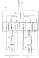
図1は、本発明の実施の形態1に係る電流センサを示す図である。本実施の形態においては、図1に示す電流センサ1は、被測定電流が流れる電流線の近傍に配設される。電流センサ1は、センサ部11と、制御部12とから主に構成されている。Hereinafter, embodiments of the present invention will be described in detail with reference to the accompanying drawings.
(Embodiment 1)
FIG. 1 is a diagram showing a current sensor according to Embodiment 1 of the present invention. In the present embodiment, the current sensor 1 shown in FIG. 1 is disposed in the vicinity of the current line through which the current to be measured flows. The current sensor 1 is mainly composed of a sensor unit 11 and a
センサ部11は、被測定電流によって発生する磁界を打ち消す方向の磁界を発生可能となるよう配置されたフィードバックコイル111と、磁気検出素子である2つの磁気抵抗効果素子及び2つの固定抵抗素子からなるブリッジ回路112とから構成されている。制御部12は、ブリッジ回路112の差動出力を増幅する差動アンプ121と、フィードバックコイルのフィードバック電流を制御する電流アンプ124と、フィードバック電流を電圧に変換するI/Vアンプ122と、磁気比例式検出及び磁気平衡式検出を切り替えるスイッチ回路123とを含む。
The sensor unit 11 includes a
フィードバックコイル111は、ブリッジ回路112の磁気抵抗効果素子の近傍に配置されており、被測定電流により発生する誘導磁界を相殺するキャンセル磁界を発生する。ブリッジ回路112の磁気抵抗効果素子としては、GMR(Giant Magneto Resistance)素子やTMR(Tunnel Magneto Resistance)素子などを挙げることができる。磁気抵抗効果素子は、被測定電流からの誘導磁界の印加により抵抗値が変化する。2つの磁気抵抗効果素子と2つの固定抵抗素子によりブリッジ回路112を構成することにより、高感度の電流センサを実現することができる。ブリッジ回路112は、被測定電流からの誘導磁界に応じた電圧差を生じる2つの出力を備える。また、磁気抵抗効果素子を用いることにより、電流センサを設置する基板面と平行な方向に感度軸を配置し易く、平面コイルを使用することが可能となる。
The
ブリッジ回路112は、被測定電流により生じた誘導磁界に応じた電圧差を生じる2つの出力を備える。ブリッジ回路112の2つの出力は差動アンプ121で増幅される。磁気比例式検出のモード(比例式モード)の場合には、差動アンプ121の電圧差がレベル調整されてセンサ出力となる。一方、磁気平衡式検出のモード(平衡式モード)の場合には、増幅された出力が電流アンプ124によりフィードバックコイル111に電流(フィードバック電流)として与えられる。このフィードバック電流は、誘導磁界に応じた電圧差に対応する。このとき、フィードバックコイル111には、誘導磁界を相殺するキャンセル磁界が発生する。そして、誘導磁界とキャンセル磁界とが相殺される平衡状態となったときのフィードバックコイル111に流れる電流がI/Vアンプ122で電圧に変換され、この電圧がセンサ出力となる。
The
なお、電流アンプ124においては、電源電圧を、I/V変換の基準電圧+(フィードバックコイル抵抗の定格内最大値 ×フルスケール時フィードバックコイル電流)に近い値に設定することで、フィードバック電流が自動的に制限され、磁気抵抗効果素子やフィードバックコイルを保護する効果が得られる。また、ここではブリッジ回路112の二つの出力の差動を増幅してフィードバック電流に用いたが、ブリッジ回路からは中点電位のみを出力とし、所定の基準電位との電位差をもとにフィードバック電流としてもよい。
In the
スイッチ回路123は、差動アンプ121からの電圧差をセンサ出力とする磁気比例式検出、及び、前記電圧差によりフィードバックコイル111に通電して誘導磁界とキャンセル磁界とが相殺される平衡状態となったときのフィードバックコイル111に流れる電流をセンサ出力する磁気平衡式検出を切り替える。このように、スイッチ回路123は、平衡式モードの際に、電流線に流れる被測定電流による誘導磁界を打ち消す磁界(キャンセル磁界)を生じさせ、比例式モードの際に、キャンセル磁界を生じさせないように回路制御を行う。すなわち、スイッチ回路123は、磁気平衡式検出モードのフィードバック電流のON/OFFを切り替える。
The
上述したように、GMR素子を用いた磁気比例式電流センサは、被測定電流が大きい場合には、その磁場によりGMR素子が磁気飽和するので、被測定電流の測定レンジが狭くなり、GMR素子を用いた磁気平衡式電流センサは、被測定電流が小さい場合に、シャント抵抗などの他の方式に比べ消費電力が大きくなる。したがって、測定レンジを広くし、しかも消費電力を少なくするためには、相対的に低い被測定電流の領域で磁気比例式検出を用い、相対的に高い被測定電流の領域で磁気平衡式検出を用いることが望ましい。また、磁気比例式検出において被測定電流の測定レンジが狭くなるのは、GMR素子が磁気飽和することが原因である。このため、磁気抵抗効果素子の磁気特性の直線性が維持される被測定電流の領域で磁気比例式検出を用いることが望ましい。 As described above, in the magnetic proportional current sensor using the GMR element, when the current to be measured is large, the GMR element is magnetically saturated by the magnetic field. The magnetic balance type current sensor used consumes more power than other methods such as a shunt resistor when the current to be measured is small. Therefore, in order to widen the measurement range and reduce power consumption, magnetic proportional detection is used in the region of relatively low measured current, and magnetic balance detection is performed in the region of relatively high measured current. It is desirable to use it. In addition, in the magnetic proportional detection, the measurement range of the current to be measured is narrowed because the GMR element is magnetically saturated. Therefore, it is desirable to use magnetic proportional detection in the region of the current to be measured where the linearity of the magnetic characteristics of the magnetoresistive element is maintained.
したがって、スイッチ回路123は、被測定電流に対して閾値判定することにより、磁気比例式検出と磁気平衡式検出とを切り替える(モード切り替え)。具体的には、低い被測定電流側で磁気比例式検出とし、それより高い被測定電流側で磁気平衡式検出とする。このとき、被測定電流の閾値は、例えば、磁気抵抗効果素子の磁気特性の直線性が維持される被測定電流にすることが望ましい。なお、磁気抵抗効果素子の磁気特性の直線性が維持される被測定電流は、磁気抵抗効果素子自体の特性や磁気抵抗効果素子とフィードバックコイルとの間の距離に起因するので、これらの要因に応じて適宜設定する。また、磁気平衡式検出から磁気比例式検出に切り替える閾値は、頻繁な切り替えを避けるためにヒステリシスを設けるのが良い。
Therefore, the
また、スイッチ回路123は、外部信号により磁気比例式検出と磁気平衡式検出とを切り替えても良い。このようにすることにより、スリープモードなど、ユーザが省電力化したいタイミングで、電流センサの消費電力を抑えることができる。この場合においては、モード信号が外部からスイッチ回路123に入力される(モード入力)。この際、GMR素子が磁気飽和するような被測定電流であった場合には、実際にはモードを切り替えないような保護機能を用意しておくことが望ましく、さらに次に述べるモード出力などを併用すれば、より状態を分かりやすくすることができる。
The
また、スイッチ回路123は、自動的にモード切り替えを行う場合には、どちらのモードで被測定電流を測定しているかの情報(磁気比例式検出状態又は磁気平衡式検出状態であることを示す信号)を外部に出力するように構成しても良い。これにより、電流センサが現在どのモードであるかを確認することができる。この場合においては、スイッチ回路123が外部モニタに接続可能に構成される。なお、スイッチ回路123において自動的にモード切り替えを行う場合には、被測定電流に対して閾値判定を行い、その結果に基づいてモード切り替えを行っても良く、電流センサが装着されている機器からの情報に基づいてモード切り替えを行っても良い。
In addition, when the mode is automatically switched, the
ここで、本発明の電流センサを用いて磁気比例式検出と磁気平衡式検出とを切り替える例について説明する。GMR素子を用いた磁気平衡式電流センサ(GMR平衡式)とGMR素子を用いた磁気比例式電流センサ(GMR比例式)の消費電力の例を図2に示す。上述したように、GMR平衡式は、被測定電流が小さい場合に、シャント抵抗などの他の方式に比べて消費電力が大きい。一方、GMR比例式は、被測定電流が大きい場合に、その磁場によりGMR素子が磁気飽和してその後の出力値が狂ってしまうため利用できない。さらに、GMR比例式では、ヒステリシスを持ったGMR素子の(非線形な)特性を直接利用するため、電流センサとして使用可能な範囲はおおよそ飽和磁場の10%弱までの線形性のある範囲に限られてしまう。図2においては、この線形性のある範囲が被測定電流換算で40A程度までである。 Here, an example of switching between magnetic proportional detection and magnetic balance detection using the current sensor of the present invention will be described. FIG. 2 shows an example of power consumption of a magnetic balance type current sensor (GMR balance type) using a GMR element and a magnetic proportional type current sensor (GMR proportional type) using a GMR element. As described above, the GMR balanced type consumes more power than other methods such as a shunt resistor when the current to be measured is small. On the other hand, the GMR proportional expression cannot be used when the current to be measured is large, because the GMR element is magnetically saturated by the magnetic field and the output value thereafter becomes incorrect. Furthermore, since the GMR proportional expression directly uses the (non-linear) characteristics of a GMR element having hysteresis, the range that can be used as a current sensor is limited to a linear range up to about 10% of the saturation magnetic field. End up. In FIG. 2, this linear range is about 40 A in terms of measured current.
本発明の電流センサを、動作時の大電流モードとそれ以外の小電流モードがはっきり分かれている例として考えられる、電気自動車やハイブリッドカーのバッテリー電流センサに適用する例を示す。例えば、ハイブリッドカーに搭載されるモータの定格が60kWであり、バッテリーが28直列であり、電圧が201.6Vとする。この場合、モータの定格運転中には、バッテリー電流は300A程度流れることとなる。一方、停車時においては、電力消費は主に電装品によるものとなり、これらを全て足しても87A(12V)であり、これは電流電圧変換してバッテリー電流にすれば5A程度となる。 An example in which the current sensor of the present invention is applied to a battery current sensor of an electric vehicle or a hybrid car, which can be considered as an example in which a large current mode during operation and a small current mode other than that are clearly separated, will be described. For example, the rating of the motor mounted on the hybrid car is 60 kW, the battery is 28 in series, and the voltage is 201.6V. In this case, during the rated operation of the motor, about 300 A of battery current flows. On the other hand, when the vehicle is stopped, the power consumption is mainly due to the electrical components, and even if all of these are added, it is 87 A (12 V), which is about 5 A if the current is converted into a battery current.
そこで、電流センサを磁気比例式検出から磁気平衡式検出へと切り替える閾値として、まず、磁気比例式検出として使用可能な範囲の50%程度と余裕のある20Aを選定する。これは、上記5Aよりも十分に大きく、上記300Aより十分に小さい値である。応答速度としては、例えば、フィードバック電流をONとし、安定するまでの時間が1μsである場合には、磁気比例式検出の使用範囲の40Aまでを考え、20A/1μs=20A/μsの電流変化に対応できるものである。これより速い電流変化の生じるシステムにおいては、同様の検討にてより余裕を持った閾値とすれば良い。逆に、磁気平衡式検出から磁気比例式検出に切り替える閾値は、頻繁な切り替えを避けるためにヒステリシスを設け、例えば20Aと5Aから適度に離れた10Aを選定するのが良い。 Therefore, as a threshold for switching the current sensor from magnetic proportional detection to magnetic balance detection, first, about 20% of the range that can be used for magnetic proportional detection and 20 A with a margin are selected. This is a value sufficiently larger than 5A and sufficiently smaller than 300A. As the response speed, for example, when the feedback current is turned ON and the time until stabilization is 1 μs, the use range of 40 A of the magnetic proportional detection is considered, and the current change is 20 A / 1 μs = 20 A / μs. It can respond. In a system in which a faster current change occurs, a threshold value with more margin may be set by the same examination. On the contrary, the threshold value for switching from magnetic balance detection to magnetic proportional detection is preferably provided with hysteresis in order to avoid frequent switching, for example, 10A that is moderately separated from 20A and 5A.
上記条件において、本発明の電流センサ(Hybrid)の消費電力を図3及び図4に示す。図4は、図3における切り替え部分を拡大した図である。図3及び図4から分かるように、被測定電流20Aを閾値として検出モードの切り替えを行うことにより、磁気平衡式検出の広い測定範囲でかつ高精度であるという利点を生かしつつ、自動車の停車時のような被測定電流が小さい場合には、消費電力を少なくすることができる。 3 and 4 show the power consumption of the current sensor (Hybrid) of the present invention under the above conditions. FIG. 4 is an enlarged view of the switching portion in FIG. As can be seen from FIGS. 3 and 4, by switching the detection mode using the measured current 20A as a threshold, while taking advantage of the wide measurement range and high accuracy of magnetic balance detection, the vehicle can be stopped. When the current to be measured is small, the power consumption can be reduced.
上記説明は、電流センサの消費電力に着目し、磁気平衡式検出モードのフィードバック電流のON/OFFを切り替える構成であるが、さらに、このフィードバック電流のON/OFFに加えて、PGA(プログラマブル・ゲイン・アンプ)などを用いて、ブリッジ回路112の差動アンプ121のゲインを変えられるように回路を構成することにより、被測定電流が小さい場合において、測定の分解能を上げることが可能となる。これは、例えば、自動車バッテリーの電流センサ用途であれば、運転時のアイドリング中や停車中における待機電流の測定精度が上がることとなり、バッテリーの充放電管理の効率を上げる効果が得られる。
The above description focuses on the power consumption of the current sensor and switches the feedback current in the magnetic balance detection mode ON / OFF. In addition to the feedback current ON / OFF, the PGA (programmable gain) is used. By configuring the circuit so that the gain of the
また、ハイブリッドカーの場合にはバッテリーの電流は直流であるが、家庭用電源などの交流の電流を測定する場合においても、本発明の構成を適用することができる。この場合の検出モードの切り替えの閾値は、例えば図3及び図4のような特性の場合には、電流の最大値(ピーク)が磁気比例式検出で使用可能な範囲の50%(20A)を超えた場合に磁気平衡式に切り替え、逆に電流の最大値が省電力モードの電流範囲、例えば10Aを下回る状態となったときに磁気比例式に切り替える、といったように設定が可能である。直流の場合のモード切り替え制御の違いは、交流変動の最大値によってのみ判断をすることであり、磁気平衡式検出として動作させている間には、交流変動周期での10A以下の電流値の時間もすべて磁気平衡式として動作させる、という点である。この場合を消費電力のグラフ(図4)上で説明をすると、(電流の最大値が20A以上の場合で)磁気平衡式として動作している間は、被測定電流の瞬時値が10A以下の時間にも、磁気平衡式検出としての電力にて動作するということである。これにより、フィードバック電流の頻繁なON/OFFを防ぎ、より大電流への変化への追従を早くできるという効果が得られる。一方、磁気比例式に切り替える閾値、例えば10Aを適切に設定できれば、磁気平衡式検出での動作の間に消費電流を抑える効果が薄れたとしても、省電力モードでは本来の狙い通り、消費電流を抑える効果が得られる。 In the case of a hybrid car, the current of the battery is a direct current, but the configuration of the present invention can also be applied when measuring an alternating current of a household power source or the like. For example, in the case of the characteristics shown in FIGS. 3 and 4, the threshold value for switching the detection mode in this case is 50% (20 A) of the range in which the maximum value (peak) of the current can be used for magnetic proportional detection. It is possible to set so that the magnetic balance type is switched when exceeding, and the magnetic proportional type is switched when the maximum current value falls below the current range of the power saving mode, for example, 10A. The difference in mode switching control in the case of direct current is that judgment is made only by the maximum value of alternating current fluctuation, and during operation as magnetic balance detection, the time of the current value of 10 A or less in the alternating current fluctuation period. Are all operated as a magnetic balance type. Explaining this case on the power consumption graph (FIG. 4), the instantaneous value of the measured current is 10 A or less while operating as a magnetic balance type (when the maximum value of the current is 20 A or more). This means that even with time, it operates with power as magnetic balance detection. As a result, it is possible to prevent the feedback current from being frequently turned on and off, and to quickly follow the change to a larger current. On the other hand, if the threshold value for switching to the magnetic proportional type, for example, 10 A, can be set appropriately, even if the effect of suppressing the current consumption during the operation in the magnetic balance type detection is weakened, the current consumption is reduced as originally intended in the power saving mode. The effect of suppressing is obtained.
このように、本発明の電流センサによれば、単一の電流センサにおいて磁気比例式検出及び磁気平衡式検出を切り替えるので、磁気平衡式による広い測定範囲と省電力化とを両立することができる。特に、本発明は、磁気抵抗効果素子を用いた電流センサであって、フィードバックコイルが近接している構成において有効である。また、磁気抵抗効果素子は、その感度軸が面内方向であるため、電流センサの製造工程において、磁気抵抗効果素子の直近にコイルを成膜することができ、結果として比較的小さいフィードバック電流で、大電流による磁場を打ち消す磁場を発生できる構成がとれる、という利点がある。 As described above, according to the current sensor of the present invention, since the magnetic proportional detection and the magnetic balance detection are switched in a single current sensor, it is possible to achieve both a wide measurement range by the magnetic balance method and power saving. . In particular, the present invention is a current sensor using a magnetoresistive effect element, and is effective in a configuration in which a feedback coil is close. In addition, since the sensitivity axis of the magnetoresistive effect element is in the in-plane direction, a coil can be formed in the immediate vicinity of the magnetoresistive effect element in the current sensor manufacturing process, and as a result, a relatively small feedback current can be obtained. There is an advantage that it is possible to generate a magnetic field that cancels a magnetic field caused by a large current.
(実施の形態2)
本実施の形態においては、被測定電流を通流する電流線を挟んで2つの電流センサが配置されており、2つの電流センサにおけるそれぞれの磁気抵抗効果素子の感度軸方向が同じである場合について説明する。(Embodiment 2)
In the present embodiment, two current sensors are arranged across a current line through which a current to be measured is passed, and the sensitivity axis directions of the magnetoresistive effect elements in the two current sensors are the same. explain.
図5は、本発明の実施の形態2に係る電流センサの配置状態を示す図である。図5に示す構成においては、被測定電流が通流する電流線2を中心に対向して2つの電流センサ1A,1Bが配設されている。 FIG. 5 is a diagram showing an arrangement state of the current sensor according to the second embodiment of the present invention. In the configuration shown in FIG. 5, two current sensors 1 </ b> A and 1 </ b> B are disposed facing the current line 2 through which the current to be measured flows.
電流センサにおいては、図6に示すように、センサ部11A,11Bは、被測定電流によって発生する磁界を打ち消す方向に巻回されたフィードバックコイル111と、磁気検出素子である2つの磁気抵抗効果素子及び2つの固定抵抗素子からなるブリッジ回路112とから構成されている。制御部13は、センサ部11Aのブリッジ回路112の差動出力を増幅する差動アンプ131と、センサ部11Aのフィードバックコイル111のフィードバック電流を制御する電流アンプ133と、センサ部11Aのフィードバック電流を電圧に変換するI/Vアンプ132と、センサ部11Bのブリッジ回路112の差動出力を増幅する差動アンプ134と、センサ部11Bのフィードバックコイル111のフィードバック電流を制御する電流アンプ135と、センサ部11Bのフィードバック電流を電圧に変換するI/Vアンプ136と、磁気比例式検出及び磁気平衡式検出を切り替えるスイッチ回路137とを含む。
In the current sensor, as shown in FIG. 6, the
図6に示す回路における各部位は図1と同じであるので、その詳細な説明は省略する。図6に示す構成において、スイッチ回路137は、電流センサ1A,1Bを同じ検出モードで動作させるように切り替え制御する。そして、スイッチ回路137は、磁気比例式検出モードにおいては、差動アンプ131,134の電圧差の差動をとってセンサ出力とし、磁気平衡式検出モードにおいては、I/Vアンプ132,136の電圧の差動をとってセンサ出力とする。このような処理を行うことにより、2つの電流センサ1A,1Bにおけるそれぞれの磁気抵抗効果素子の感度軸方向は同じであるため地磁気などの外部磁場はキャンセルされ、より高精度に電流を測定することができる。
Each part in the circuit shown in FIG. 6 is the same as that shown in FIG. In the configuration shown in FIG. 6, the
(電流センサを用いたバッテリー)
本発明の電流センサを用いたバッテリーは、電流線を備えたバッテリー本体と、この電流線に取り付けられた電流センサとを具備する。このような構成を有するバッテリーにおいて充放電制御を行ってバッテリーのマネジメントを行う場合(バッテリーマネジメントシステム)について説明する。(Battery using current sensor)
A battery using the current sensor of the present invention includes a battery main body provided with a current line, and a current sensor attached to the current line. A case where battery management is performed by performing charge / discharge control in a battery having such a configuration (battery management system) will be described.
本実施の形態で示した電流センサは、バッテリーに設けることにより、バッテリーの管理を行うことができる。具体的には、図7に示すように、Liイオン電池、NiMH電池、鉛蓄電池等の充放電を行うバッテリーの端子(プラス極又はマイナス極)に電流センサを設け、当該電流センサを用いてバッテリーの充放電の電流を計測し、積算することによりバッテリーの残量管理を行うことができる。 The current sensor described in this embodiment can be managed by being provided in the battery. Specifically, as shown in FIG. 7, a current sensor is provided at a terminal (plus or minus pole) of a battery that performs charging / discharging such as a Li ion battery, a NiMH battery, or a lead storage battery, and the battery using the current sensor is provided. The remaining amount of the battery can be managed by measuring and integrating the charge / discharge current.
バッテリーの使用時の場合と未使用時の場合とで流れる電流値は大きく異なるが、本実施の形態で示した電流センサを用いることにより、すなわち、被測定電流が低い場合に磁気比例式検出とし、被測定電流が高い場合に磁気平衡式検出とすることにより、一つの電流センサで使用時と未使用時の電流量を高い精度で検出することができる。バッテリーの電流値を高精度で測定することにより、積算誤差が低下することが可能となるため、過充電、過放電のためにバッテリーに設けるマージンを小さくすることができる。その結果、バッテリーを効率的に使用することが可能となり、例えば、電気自動車などのバッテリーに本実施の形態で示す電流センサを適用することにより、走行距離を延ばすことができる。 The value of the current that flows when the battery is used and when it is not used differs greatly, but by using the current sensor shown in this embodiment, that is, when the measured current is low, magnetic proportional detection is used. By using magnetic balance detection when the current to be measured is high, a single current sensor can detect the amount of current during use and when not used with high accuracy. By measuring the current value of the battery with high accuracy, the integration error can be reduced, so that a margin provided in the battery for overcharge and overdischarge can be reduced. As a result, the battery can be used efficiently. For example, the travel distance can be extended by applying the current sensor described in this embodiment to a battery of an electric vehicle or the like.
本発明は上記実施の形態1,2に限定されず、種々変更して実施することができる。例えば、上記実施の形態1,2における各素子の接続関係、大きさなどは適宜変更して実施することが可能である。また、上記実施の形態においては、磁気平衡式電流センサに磁気抵抗効果素子を用いた場合について説明しているが、磁気平衡式電流センサにホール素子やその他の磁気検出素子を用いて構成してもよい。その他、本発明は、本発明の範囲を逸脱しないで適宜変更して実施することができる。 The present invention is not limited to the first and second embodiments, and can be implemented with various modifications. For example, the connection relation and size of each element in the first and second embodiments can be changed as appropriate. Further, in the above embodiment, a case where a magnetoresistive effect element is used for the magnetic balance type current sensor has been described. However, a Hall element or other magnetic detection element is used for the magnetic balance type current sensor. Also good. In addition, the present invention can be implemented with appropriate modifications without departing from the scope of the present invention.
本発明は、電気自動車やハイブリッドカーのモータ駆動用の電流の大きさを検出する電流センサに適用することが可能である。 The present invention can be applied to a current sensor that detects the magnitude of a current for driving a motor of an electric vehicle or a hybrid car.
本出願は、2010年2月23日出願の特願2010−037456に基づく。この内容は、全てここに含めておく。 The present application is based on Japanese Patent Application No. 2010-037456 filed on Feb. 23, 2010. All this content is included here.
Claims (5)
前記ブリッジ回路の出力を増幅する差動アンプと、
前記磁気抵抗効果素子の近傍に配置され、前記誘導磁界を相殺するキャンセル磁界を発生するフィードバックコイルと、
前記差動アンプからの出力を基に前記キャンセル磁界を発生させるように前記フィードバックコイルに供給する電流を制御する電流アンプと、
前記フィードバックコイルに流れた電流を電圧に変換するI/Vアンプと、
前記差動アンプの出力と前記I/Vアンプの出力とを切り替えて出力するスイッチ回路とを具備し、
前記被測定電流の発生する磁場の大きさが前記磁気抵抗効果素子の磁気特性の直線性が維持される第1の領域である場合に、前記差動アンプの出力を前記スイッチ回路が出力する磁気比例式を選択し、
前記被測定電流の発生する磁場の大きさが前記第1の領域より大きく、前記磁気特性の直線性が維持されない第2の領域である場合に、前記電流アンプで制御された電流を前記フィードバックコイルに通電して、前記I/Vアンプの出力を前記スイッチ回路が出力する磁気平衡式を選択する
電流センサ。 A bridge circuit configured by combining a magnetoresistive effect element whose characteristics change due to an induced magnetic field from a current to be measured and a fixed resistance element;
A differential amplifier for amplifying the output of the bridge circuit;
A feedback coil disposed in the vicinity of the magnetoresistive element and generating a canceling magnetic field that cancels the induced magnetic field;
A current amplifier for controlling a current supplied to the feedback coil so as to generate the canceling magnetic field based on an output from the differential amplifier;
An I / V amplifier that converts a current flowing through the feedback coil into a voltage;
A switch circuit for switching and outputting the output of the differential amplifier and the output of the I / V amplifier;
When the magnitude of the magnetic field generated by the current to be measured is the first region where the linearity of the magnetic characteristics of the magnetoresistive effect element is maintained, the magnetism that the switch circuit outputs the output of the differential amplifier Select a proportional expression,
When the magnitude of the magnetic field generated by the current to be measured is larger than the first area and the second area where the linearity of the magnetic characteristics is not maintained, the current controlled by the current amplifier is supplied to the feedback coil. A current sensor that selects a magnetic balance type in which the switch circuit outputs the output of the I / V amplifier.
A battery comprising: a battery main body provided with a current line; and the current sensor according to claim 1 attached to the current line.
Priority Applications (1)
| Application Number | Priority Date | Filing Date | Title |
|---|---|---|---|
| JP2012501728A JP5604652B2 (en) | 2010-02-23 | 2011-02-08 | Current sensor |
Applications Claiming Priority (4)
| Application Number | Priority Date | Filing Date | Title |
|---|---|---|---|
| JP2010037456 | 2010-02-23 | ||
| JP2010037456 | 2010-02-23 | ||
| JP2012501728A JP5604652B2 (en) | 2010-02-23 | 2011-02-08 | Current sensor |
| PCT/JP2011/052657 WO2011105209A1 (en) | 2010-02-23 | 2011-02-08 | Current sensor |
Publications (2)
| Publication Number | Publication Date |
|---|---|
| JPWO2011105209A1 JPWO2011105209A1 (en) | 2013-06-20 |
| JP5604652B2 true JP5604652B2 (en) | 2014-10-08 |
Family
ID=44506625
Family Applications (1)
| Application Number | Title | Priority Date | Filing Date |
|---|---|---|---|
| JP2012501728A Active JP5604652B2 (en) | 2010-02-23 | 2011-02-08 | Current sensor |
Country Status (4)
| Country | Link |
|---|---|
| US (1) | US8465859B2 (en) |
| JP (1) | JP5604652B2 (en) |
| CN (1) | CN102812366B (en) |
| WO (1) | WO2011105209A1 (en) |
Families Citing this family (14)
| Publication number | Priority date | Publication date | Assignee | Title |
|---|---|---|---|---|
| ATE545871T1 (en) * | 2009-06-17 | 2012-03-15 | Nxp Bv | MAGNETIC FIELD SENSOR |
| JP2011164019A (en) * | 2010-02-12 | 2011-08-25 | Alps Green Devices Co Ltd | Current measuring device |
| WO2012011306A1 (en) * | 2010-07-20 | 2012-01-26 | アルプス・グリーンデバイス株式会社 | Current sensor |
| JP5728719B2 (en) * | 2011-12-28 | 2015-06-03 | アルプス・グリーンデバイス株式会社 | Current sensor |
| US9625534B2 (en) * | 2012-11-21 | 2017-04-18 | Allegro Microsystems, Llc | Systems and methods for detection of magnetic fields |
| TWI499791B (en) | 2013-12-20 | 2015-09-11 | Ind Tech Res Inst | A compensating apparatus for a non-contact current sensor installing variation in two wire power cable |
| JPWO2015111163A1 (en) * | 2014-01-23 | 2017-03-23 | 三菱電機株式会社 | Magnetic detector |
| US9762071B2 (en) * | 2014-11-13 | 2017-09-12 | Servato Corp. | Battery management circuit and related techniques using MOSFET power switch with intelligent switch control |
| CN107533088B (en) * | 2015-07-22 | 2019-10-18 | 株式会社村田制作所 | Current sensor |
| CN105606877B (en) * | 2016-02-22 | 2019-01-04 | 宁波中车时代传感技术有限公司 | A kind of closed loop TMR current sensor |
| JP7140149B2 (en) * | 2020-01-31 | 2022-09-21 | Tdk株式会社 | Current sensors, magnetic sensors and circuits |
| JP7106591B2 (en) * | 2020-03-18 | 2022-07-26 | Tdk株式会社 | Magnetic field detector and current detector |
| JP7273876B2 (en) | 2021-03-08 | 2023-05-15 | Tdk株式会社 | Magnetic sensor device, inverter device and battery device |
| US20240027501A1 (en) * | 2022-07-20 | 2024-01-25 | GM Global Technology Operations LLC | Positioning and correction of current sensing devices |
Citations (3)
| Publication number | Priority date | Publication date | Assignee | Title |
|---|---|---|---|---|
| JP2002243816A (en) * | 2001-02-16 | 2002-08-28 | Fuji Electric Co Ltd | Magnetic detector |
| JP2007078416A (en) * | 2005-09-12 | 2007-03-29 | Denso Corp | Current sensor and current sensing method |
| JP2007163424A (en) * | 2005-12-16 | 2007-06-28 | Japan Aviation Electronics Industry Ltd | Flux gate type magnetic sensor |
Family Cites Families (3)
| Publication number | Priority date | Publication date | Assignee | Title |
|---|---|---|---|---|
| CN2385339Y (en) * | 1999-07-09 | 2000-06-28 | 保定市霍尔电子有限公司 | Magnetic balancing current sensor for current measuring sampling |
| CN2522866Y (en) * | 2002-04-02 | 2002-11-27 | 华北电力大学(北京) | Electric energy mass on-line monitoring apparatus based on virtual instrument technology |
| WO2011111493A1 (en) * | 2010-03-12 | 2011-09-15 | アルプス・グリーンデバイス株式会社 | Current sensor |
-
2011
- 2011-02-08 JP JP2012501728A patent/JP5604652B2/en active Active
- 2011-02-08 CN CN201180010192.9A patent/CN102812366B/en not_active Expired - Fee Related
- 2011-02-08 WO PCT/JP2011/052657 patent/WO2011105209A1/en active Application Filing
-
2012
- 2012-06-22 US US13/531,445 patent/US8465859B2/en active Active
Patent Citations (3)
| Publication number | Priority date | Publication date | Assignee | Title |
|---|---|---|---|---|
| JP2002243816A (en) * | 2001-02-16 | 2002-08-28 | Fuji Electric Co Ltd | Magnetic detector |
| JP2007078416A (en) * | 2005-09-12 | 2007-03-29 | Denso Corp | Current sensor and current sensing method |
| JP2007163424A (en) * | 2005-12-16 | 2007-06-28 | Japan Aviation Electronics Industry Ltd | Flux gate type magnetic sensor |
Also Published As
| Publication number | Publication date |
|---|---|
| WO2011105209A1 (en) | 2011-09-01 |
| JPWO2011105209A1 (en) | 2013-06-20 |
| US8465859B2 (en) | 2013-06-18 |
| US20120263985A1 (en) | 2012-10-18 |
| CN102812366B (en) | 2015-03-11 |
| CN102812366A (en) | 2012-12-05 |
Similar Documents
| Publication | Publication Date | Title |
|---|---|---|
| JP5604652B2 (en) | Current sensor | |
| JP5699301B2 (en) | Current sensor | |
| JP5531213B2 (en) | Current sensor | |
| US8970214B2 (en) | Current sensor | |
| WO2012011306A1 (en) | Current sensor | |
| JP5584918B2 (en) | Current sensor | |
| WO2012070337A1 (en) | Current sensor | |
| WO2012053296A1 (en) | Current sensor | |
| JP2011164027A (en) | Current sensor and battery with current sensor | |
| JP2008215970A (en) | Bus bar integrated current sensor | |
| JP5487403B2 (en) | Current sensor | |
| JP2007033222A (en) | Current sensor | |
| JP5891516B2 (en) | Current sensor | |
| JP5531216B2 (en) | Current sensor | |
| JP2007040758A (en) | Current sensor | |
| US20240118319A1 (en) | Current detection device and related devices, systems and methods thereof | |
| JP2005345267A (en) | Current sensor | |
| JP2005351701A (en) | Current detecting apparatus |
Legal Events
| Date | Code | Title | Description |
|---|---|---|---|
| RD02 | Notification of acceptance of power of attorney |
Free format text: JAPANESE INTERMEDIATE CODE: A7422 Effective date: 20130620 |
|
| A521 | Request for written amendment filed |
Free format text: JAPANESE INTERMEDIATE CODE: A523 Effective date: 20130710 |
|
| A131 | Notification of reasons for refusal |
Free format text: JAPANESE INTERMEDIATE CODE: A131 Effective date: 20131105 |
|
| RD04 | Notification of resignation of power of attorney |
Free format text: JAPANESE INTERMEDIATE CODE: A7424 Effective date: 20131120 |
|
| A521 | Request for written amendment filed |
Free format text: JAPANESE INTERMEDIATE CODE: A523 Effective date: 20131224 |
|
| A521 | Request for written amendment filed |
Free format text: JAPANESE INTERMEDIATE CODE: A523 Effective date: 20131220 |
|
| TRDD | Decision of grant or rejection written | ||
| A01 | Written decision to grant a patent or to grant a registration (utility model) |
Free format text: JAPANESE INTERMEDIATE CODE: A01 Effective date: 20140710 |
|
| A61 | First payment of annual fees (during grant procedure) |
Free format text: JAPANESE INTERMEDIATE CODE: A61 Effective date: 20140725 |
|
| R150 | Certificate of patent or registration of utility model |
Ref document number: 5604652 Country of ref document: JP Free format text: JAPANESE INTERMEDIATE CODE: R150 |
|
| S111 | Request for change of ownership or part of ownership |
Free format text: JAPANESE INTERMEDIATE CODE: R313111 |
|
| R350 | Written notification of registration of transfer |
Free format text: JAPANESE INTERMEDIATE CODE: R350 |
|
| S533 | Written request for registration of change of name |
Free format text: JAPANESE INTERMEDIATE CODE: R313533 |
|
| R350 | Written notification of registration of transfer |
Free format text: JAPANESE INTERMEDIATE CODE: R350 |