JP5601769B2 - Fishing line guide - Google Patents
Fishing line guide Download PDFInfo
- Publication number
- JP5601769B2 JP5601769B2 JP2008312466A JP2008312466A JP5601769B2 JP 5601769 B2 JP5601769 B2 JP 5601769B2 JP 2008312466 A JP2008312466 A JP 2008312466A JP 2008312466 A JP2008312466 A JP 2008312466A JP 5601769 B2 JP5601769 B2 JP 5601769B2
- Authority
- JP
- Japan
- Prior art keywords
- fishing line
- line guide
- frame
- rod
- diameter
- Prior art date
- Legal status (The legal status is an assumption and is not a legal conclusion. Google has not performed a legal analysis and makes no representation as to the accuracy of the status listed.)
- Active
Links
Images


Description
本発明は、釣り糸ガイドに関し、特にフレームに釣糸案内部と固定部とを形成し、この固定部を筒状体の受け部に装着した釣り糸ガイドに関する。 The present invention relates to a fishing line guide, and more particularly to a fishing line guide in which a fishing line guide portion and a fixing portion are formed on a frame , and the fixing portion is attached to a receiving portion of a cylindrical body.
一般に、釣り糸ガイドは、釣り糸が釣り竿の表面に付着するのを防止するために、間隔をおいて釣り竿の外側に取付けられる。このような釣り糸ガイドには、糸通し環を支える金属製フレームをプラスチック製の竿保護管に固定したものが開発されている(例えば特許文献1参照)。 In general, the fishing line guide is attached to the outside of the fishing rod at an interval in order to prevent the fishing line from adhering to the surface of the fishing rod. Such fishing line guides have been developed in which a metal frame that supports a threading ring is fixed to a plastic rod protection tube (see, for example, Patent Document 1).
このプラスチック製の竿保護管は、フレームを装着する部位の後端側すなわち釣り竿の元側に、フレームの回り止め突起を形成すると共に、この後方で弾性変形する円筒部を後方に向けて径を小さくしたテーパ状に形成してある。また、フレームは、プレス加工により板状に形成し、竿保護管に固定する部分は、絞り加工により、水平部を有する管形に形成し、この管形の部分に回り止め用の切欠き部を形成してある。 This plastic rod protection tube is formed with a detent projection of the frame on the rear end side of the part where the frame is to be attached, that is, on the base side of the fishing rod. It is formed in a reduced taper shape. In addition, the frame is formed into a plate shape by pressing, and the portion that is fixed to the saddle protection tube is formed into a tubular shape having a horizontal portion by drawing, and a notch portion for preventing rotation is added to this tubular portion. Is formed.
このフレームを竿保護管に装着する際は、竿保護管の小径に形成した後方から管形の部分を挿入し、円筒部を弾性変形により縮径させつつ前方に向けて圧入し、回り止め突起に管形部分の切欠き部を嵌合することで、回り止め突起を損傷することなく、竿保護管上の所定位置にフレームを確実に固定するものである。
しかし、従来の釣り糸ガイドは、釣り竿に取付けたときに、竿保護管が、フレームを挿入する側すなわちテーパ状形状の小径部を元側に配置することになり、釣り竿の外周面上で竿保護管が段差を形成し、更に、竿保護管とフレームとの径差により段差が形成される。これらの段差は、フレームよりも元側すなわち魚釣用リールに近接する側に位置するため、釣り糸が引っ掛かり易く、糸ガラミし易い
本発明は、このような事情に基づいてなされたもので、釣り糸が絡まり難く、軽量化、小型化が図れ、釣り糸案内特性に優れた釣り糸ガイドを提供することを目的とする。
However, when the conventional fishing line guide is attached to a fishing rod, the rod protection tube will be arranged on the side where the frame is inserted, that is, the tapered small diameter portion on the original side, protecting the rod on the outer peripheral surface of the fishing rod. The tube forms a step, and further, the step is formed by the difference in diameter between the heel protection tube and the frame. Since these steps are located on the original side of the frame, that is, on the side closer to the fishing reel, the fishing line is easily caught and the yarn is easily crushed. It is an object of the present invention to provide a fishing line guide that is less likely to get tangled, can be reduced in weight and size, and has excellent fishing line guide characteristics.
上記目的を達成するため、本発明によると、フレームに釣り糸案内部と固定部とを形成し、この固定部を筒状体の受け部に装着し、釣り竿の前方の穂先側から後方の元側に沿って竿杆上を前後動し、この竿杆の外周上に保持される釣り糸ガイドであって、前記フレームは、前記釣り糸案内部と前記固定部との間に配置される連結部を有し、この連結部は、前記固定部との間に段部を形成することなく滑らかに湾曲しつつ前記釣り糸案内部に連続し、前記フレームの前記釣り糸案内部は前記固定部に対して軸方向の前方に傾斜し、前記筒状体は、前記受け部の軸方向前側に配置された小径部と軸方向後側に配置された大径部とを有し、前記大径部は、軸方向に沿う竿杆挿入孔の後端周縁部から前方に向かって湾曲する湾曲面状の外周面を有し、前記フレームの前記固定部は、前記連結部の側縁部に連続し、かつ前記大径部よりも2mm以内の範囲でこの大径部から外方に突出する外側部を有し、この外側部を前記釣り糸案内部と同程度の平滑面に形成する釣り糸ガイドが提供される。 To achieve the above object, according to the present invention, to form a fixing portion fishing Ri thread guide portion to the frame, fitted with the fixed portion to the receiving portion of the tubular body, the front of the rod from the tip side behind the moving back and forth a rod杆上along the original side, a fishing line guide that is held on the outer periphery of this rod rod, the frame, the connecting portion disposed between the stationary portion and the fishing line guide portion the a, the connecting portion is continuous with the fishing line guide portion while smoothly curved without forming a step portion between the fixing portion, the fishing line guide portion of the frame relative to the fixed part Inclined forward in the axial direction, the cylindrical body has a small diameter portion disposed on the front side in the axial direction of the receiving portion and a large diameter portion disposed on the rear side in the axial direction. have a curved surface shaped outer peripheral surface of which is curved toward the front from the rear end periphery of the rod rod insertion hole along the axial direction, The fixed portion of the frame has an outer portion that is continuous with a side edge portion of the connecting portion and protrudes outward from the large diameter portion within a range of 2 mm from the large diameter portion. Is provided on a smooth surface comparable to the fishing line guide portion .
更に、フレームに釣り糸案内部と固定部とを形成し、この固定部を筒状体の受け部に装着し、釣り竿の前方の穂先側から後方の元側に沿って竿杆上を前後動し、この竿杆の外周上に保持される釣り糸ガイドであって、前記フレームは、前記釣り糸案内部と前記固定部との間に配置される連結部を有し、この連結部は、前記固定部との間に段部を形成することなく滑らかに湾曲しつつ前記釣り糸案内部に連続し、前記フレームの前記釣り糸案内部は前記固定部に対して軸方向の前方に傾斜し、前記筒状体は、前記受け部の軸方向前側に配置された小径部と軸方向後側に配置された大径部とを有し、前記大径部は、軸方向に沿う竿杆挿入孔の後端周縁部から前方に向かって順に拡径する外周面を有し、前記小径部は、拡径した厚肉部を有し、前記フレームの前記固定部は、前記連結部の側縁部に連続し、かつ前記大径部よりも2mm以内の範囲でこの大径部から外方に突出する外側部を有し、この外側部を前記釣り糸案内部と同程度の平滑面に形成する釣り糸ガイドが提供される。 Furthermore, to form a fixing portion fishing Ri thread guide portion to the frame, the fixed portion is attached to the receiving portion of the tubular body, before and after the rod杆上from the tip side of the front of the fishing rod along the original side of the rear dynamic and, a fishing line guide that is held on the outer periphery of this rod rod, the frame has a connecting portion disposed between the fishing line guide portion and the fixed portion, the connecting portion, the continuously to the fishing line guide portion while smoothly curved without forming a step portion between the fixed portion, the fishing line guide portion of the frame is inclined forward in the axial direction with respect to the fixed portion, the cylindrical The state body has a small-diameter portion disposed on the front side in the axial direction of the receiving portion and a large-diameter portion disposed on the rear side in the axial direction, and the large-diameter portion is disposed behind the flange insertion hole along the axial direction. It has an outer peripheral surface that sequentially increases in diameter toward the front from the end periphery, the small diameter portion, have a diameter the thick portion, wherein The fixing portion of the lem has an outer portion that is continuous with the side edge portion of the connecting portion and protrudes outward from the large diameter portion within a range of 2 mm from the large diameter portion. There is provided a fishing line guide formed on a smooth surface comparable to the fishing line guide.
前記フレームの固定部は、この連結部の側縁部に連続し、かつ前記大径部よりも2mm以内の範囲でこの大径部から外方に突出する外側部を有し、この外側部を前記釣り糸案内部と同程度の平滑面に形成したものであってもよい。 Fixed part of the frame has an outer portion projecting from the large diameter portion at the side edges contiguous to the portion, and the range within 2mm than the large diameter portion of the connecting portion outwardly, the outer portion It may be formed on the same smooth surface as the fishing line guide.
前記大径部は、小径部よりも2倍以上の軸方向長さを有することが好ましい。 The large-diameter portion preferably has an axial length twice or more that of the small-diameter portion .
前記フレームの釣り糸案内部と固定部とは、それぞれ前方に突出する突部を有し、前記固定部の突部が突出する長さは、釣り糸案内部の突部よりも短くかつフレームの肉厚以下とすることができる。 Each of the fishing line guide portion and the fixing portion of the frame has a protrusion protruding forward, and the length of the protrusion of the fixing portion protruding is shorter than the protrusion of the fishing line guide portion and the thickness of the frame. It can be as follows.
筒状体の大径部が、軸方向に沿う竿杆挿入孔の後端周縁部から前方に向かって湾曲する湾曲面状の外周面を有する釣り糸ガイドにあっては、フレームの後方に、段差が形成されず、大径部に係合した釣り糸は、湾曲面状の外周面に沿って前方に移動され、これにより、釣り糸が後筒部に当たった場合でも、特別な部材を必要とすることなく、釣り糸を外周面に沿って釣り糸案内部に案内することができ、更に、フレームの連結部が固定部との間に段部を形成することないため、糸ガラミが発生し難く、軽量化、小型化が図れ、釣り糸案内特性に優れた釣り糸ガイドを形成することができる。 In a fishing line guide having a curved outer peripheral surface in which the large-diameter portion of the cylindrical body is curved forward from the rear end peripheral portion of the rod insertion hole along the axial direction, a step is provided behind the frame. Is not formed, and the fishing line engaged with the large-diameter portion is moved forward along the outer peripheral surface of the curved surface, so that a special member is required even when the fishing line hits the rear tube portion. The fishing line can be guided along the outer peripheral surface to the fishing line guide part, and the connecting part of the frame does not form a step part between the fixed part, so that it is difficult to cause line glare and light weight. Therefore, a fishing line guide having excellent fishing line guide characteristics can be formed.
また、筒状体の大径部が前方に向かって順に拡径する外周面を有し、小径部が拡径した厚肉部を有する釣り糸ガイドにあっては、フレームの後方に、段差が形成されず、大径部に係合した釣り糸は、外周面に沿って前方に移動され、釣り糸が大径部に当たった場合でも、特別な部材を必要とすることなく、釣り糸を外周面に沿って釣り糸案内部に案内することができ、更に、フレームの連結部が固定部との間に段部を形成することないため、糸ガラミが発生し難く、更に、小径部の厚肉部は、特別な部材を設けることなく、前部における強度を向上することで、筒状体の前端部および後端部からの割れや破損を防止し、釣り竿上で安定した状態に配置することができ、これにより、軽量化、小型化が図れ、釣り糸案内特性に優れた釣り糸ガイドを形成することができる。 Further, in the fishing line guide having the outer peripheral surface in which the large-diameter portion of the cylindrical body expands in order toward the front and the thick- diameter portion in which the small-diameter portion expands, a step is formed at the rear of the frame. The fishing line engaged with the large diameter portion is moved forward along the outer peripheral surface, and even if the fishing line hits the large diameter portion , the fishing line is moved along the outer peripheral surface without requiring a special member. can be guided to the fishing line guide portion Te, further, since never connecting portion of the frame to form a stepped portion between the fixed portion, the thread Garami hardly occurs, further, the thick portion of the small-diameter portion, Without providing a special member, by improving the strength at the front portion, it can be prevented from cracking and breakage from the front end portion and the rear end portion of the cylindrical body, can be placed in a stable state on the fishing rod, This makes it possible to reduce the weight and size of the fishing line guide with excellent fishing line guide characteristics. It can be formed.
また、フレームの固定部が、大径部よりも外方に突出する外側部を釣り糸案内部と同程度の平滑面に形成されている場合には、この外側部で釣り糸が滑り易く、より確実に糸ガラミを防止することができる。 In addition, when the outer part of the frame fixing part is formed on the same smooth surface as the fishing line guide part, the outer part of the fixed part of the frame protrudes outward from the large-diameter part. It is possible to prevent yarn glare.
筒状体の大径部が、フレームの抜け止めとして作用する小径部よりも2倍以上の軸方向長さを有する場合には、筒状体の前後における形状および強度をバランスさせ、竿杆に取付けた際の釣り糸ガイドの全体のバランスを好適に維持しつつ強度向上を図ることができる。 When the large-diameter portion of the cylindrical body has an axial length more than twice as long as the small-diameter portion that acts as a retainer for the frame, balance the shape and strength of the cylindrical body before and after , Strength improvement can be aimed at maintaining the balance of the whole fishing line guide at the time of attaching suitably.
また、釣り糸案内部と固定部とが、それぞれ前方に突出する突部を有し、固定部の突部が突出する長さを、釣り糸案内部の突部よりも短くかつフレームの肉厚以下とする場合には、フレームの軽量化、小型化が可能で、更に、釣り糸案内部の突部が相対的に大きく形成され、釣り糸の案内特性に優れた釣り糸ガイドを係止することができる。 Further, the fishing line guide portion and the fixing portion each have a protrusion protruding forward, and the length of the protrusion of the fixing portion protruding is shorter than the protrusion of the fishing line guide portion and not more than the thickness of the frame. In this case, the weight of the frame can be reduced and the size of the frame can be reduced. Further, the protrusion of the fishing line guide portion is relatively large, and the fishing line guide having excellent fishing line guiding characteristics can be locked.
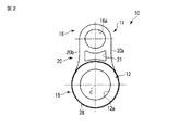
図1から図4は、本発明の好ましい実施形態による釣り糸ガイド10を示す。
1-4 show a
本実施形態の釣り糸ガイド10は、釣り竿の竿杆8(図3)の外面に釣り糸tが付着するのを防止する外ガイドとして形成してあり、僅かな勾配を形成された竿杆8の外周上を、前方の穂先側8aから後方の元側8bに沿って、竿杆8の軸線Cと平行な軸方向に前後動し、所要位置に摩擦力で保持することができる。必要な場合には、接着剤等の適宜の固定手段により、所要位置に移動不能に固定することも可能である。
The
この釣り糸ガイド10は、竿杆挿入孔として滑らかな内周面を有する内孔12aを軸方向に貫通させた筒状体12に、金属製フレーム14を装着し、この内孔12aに挿通した竿杆8上を所要位置に移動し、フレーム14に形成した釣り糸案内部16を介して釣り糸tを案内する。必要な場合には、竿杆8の好適位置に、筒状体12を固定するための大径化部(図示しない)を形成してもよい。
This
本実施形態のフレーム14は、釣り糸を案内するリング状の釣り糸案内部16と、筒状体12に固定するリング状の固定部18とを連結部20で一体化した板状に形成してある。この連結部20は、ほぼ中央部位に、軽量化を図る開口21を形成し、側縁部20a,20bは、固定部18から釣り糸案内部16の外端に向けて次第に幅が狭まる滑らかな凹曲線あるいは凹曲面で形成してある。このフレーム14の釣り糸案内部16、固定部18および連結部20の外周に沿う縁部は、釣り糸ガラミを防止するため、全体にわたって板厚d(図4)方向にも丸みを付けられ、同様に、開口21の周縁部も、板厚方向に丸みを付けてある。
The
連結部20の上方に配置される釣り糸案内部16は、固定部18に対して軸方向の前方に向けて傾斜し、軸線Cに垂直に配置される固定部16との間に角度θを形成する。また、釣り糸案内部16を支える連結部20は、固定部18との間に段部を形成することなく、滑らかに湾曲しつつ釣り糸案内部16に連続し、釣り糸案内部16と共に、釣り糸を前方に案内し易くしてある。この角度θは、釣り糸ガラミを防止できるものであれば、例えば5°〜45°、好ましくは15°〜45°の範囲で適宜に設定することができる。この釣り糸ガイド10の角度θは、穂先側よりも元側で小さくし、図示しない魚釣用リールに近い側で、ガイド孔16aの開口面積を大きくしてもよい。
The fishing
このフレーム14は、釣り糸案内部16に形成した円形状のガイド孔16aを、釣り糸が引っ掛かり難い滑らかな曲面状の釣り糸案内面22で囲んである。この釣り糸案内面22は、例えばガイド孔16aの周部をカーリング加工する等、適宜の方法により、フレーム14と一体の突部24の内面側で形成することもできる。あるいは、セラミックス製等の他の硬質材で形成したリング部材等をガイド孔16aに固定し、このような別体のリング部材で釣り糸案内面を形成することも可能である。いずれの場合も、釣り糸案内面22は、フレーム14の後方側の側面から、突部24の前端を介して前方側の側面まで、滑らかに連続する曲面状に形成することが好ましい。この突部24がフレーム14の前面から突出する突出量d1は、フレーム14の板厚dよりも大きいことが好ましい。
The
連結部20の下方に配置される固定部18は、筒状体12の受け部(後述する)に装着するための円形状の装着孔18aを有し、この装着孔18の周部の一部に、回り止め凹部18bを形成してある。この固定部18は、装着孔18の周部に、例えばバーリング加工した突部26を形成してあり、筒状体12の受け部との接触面積を増大し、筒状体12の受け部に安定した状態で保持される。
The
突部26がフレーム14の前面から突出する突出量d2は、フレーム14の板厚dの寸法以下で、釣り糸案内部16に設けた突部24の突出量d1よりも少ないことが好ましい。釣り糸案内部16および固定部18の突部24,26の突出量d1、d2をこのように形成することにより、フレーム14および釣り糸ガイド10の小型、軽量化を図りつつ釣り糸の案内性を向上させることができる。
The protrusion amount d2 from which the
また、外周縁部28は、後述する筒状体12の大径部と同径又は僅かに大きな外径を有し、筒状体12の受け部に装着したときに、大径部よりも2mm以内の範囲、好ましくは釣り糸tの径の半分以下の大きさだけ突出する。この外周縁部28の周面が上述のようにフレーム14の板厚方向に丸みを付けた曲面状に形成されているため、筒状体12から突出した場合でも、釣り糸が絡まり難い状態に配置される。
The outer
このように形成されるフレーム14は、例えばマグネシウム、ステンレス鋼、チタン、チタン合金、アルミニウム、アルミニウム合金等の金属、繊維強化樹脂(FRP)又は繊維強化金属(FRM)等の適宜の材料で形成することができる。そして、外部に露出する部分、特に釣り糸案内部16、連結部20、固定部18の外周縁部28、釣り糸案内面22、開口21の内周面、および、フレーム14の周側面を鏡面研磨し、釣り糸の引っかかり、絡みを防止する状態とすることが好ましい。特に、固定部18の外周縁部28を釣り糸案内部16と同程度の平滑面に形成する場合は、この外周縁部28が筒状体12から径方向外方に突出しても、この外周縁部28で釣り糸が係止されることはなく、糸ガラミを確実に防止することができる。
図4に示すように、このフレーム14を支える筒状体12は、後方に配置される後筒部である大径部と、フレーム14の固定部18を装着する受け部32と、前方に配置される前筒部である小径部34とを有し、受け部32の周部に、フレーム14に形成した回り止め凹部18bに嵌合する回り止め突起36を形成してある。図示の実施形態では、回り止め凹部18bおよび回り止め突起36をそれぞれ1つずつ形成してあるが、複数設けることも可能なことは明らかである。
As shown in FIG. 4, the
大径部30は、内孔12aの後端周縁部から前方に向けて拡径する滑らかな湾曲面状の外周面すなわち楕円球状又は球状に湾曲する球面状部30aを後側に有し、この球面状部30aに連続する円筒状部30bを前側に有する。球面状部30aは、後端部が内孔12aの後端周縁部に連続し、軸線cに対して90°以下で、好ましくは80°〜30°の鋭角状の立上がり角度α(図3)を形成する。この球面状部30aは、後端側で曲率が大きく形成され、前方に向けて徐々に曲率が小さくなり、円筒状部30bに滑らかに移行する。球面状部30aの後端の立上がり角度αが鋭角状に形成されることで、後端側の曲率が大きく形成されていても、この後端に釣り糸が引っ掛かったり、絡まってしまうことなく、釣り糸は球面状部30aから前方に向けて滑らかに移動される
このような湾曲面で外周面を形成された大径部30は、竿杆8に装着されたときに、この竿杆8の外周面との間に、釣り糸tを係止する大きさの段部を形成することはない。また、球面状部30aの前部に形成される円筒状部30bは、受け部32との間に軸線Cにほぼ垂直な前端面38を形成し、受け部32に装着したフレーム14の固定部18の後側の側面を、この前端部38に当接させた状態で保持することができる。
The large-
フレーム14の固定部18を装着して一体的に固定する受け部32は、固定部18を突部26と共に強固に保持する構造を備えており、小径部34は後方に向けて僅かに拡径し、受け部32に圧入された状態の固定部18の抜け止め部を形成する。ここに、固定部18と受け部32とを一体的に固定することは、フレーム14の固定部18を受け部32に圧入嵌合すること、嵌合接着すること、又はこれらの組み合わせにより、取れたり外れたりしない状態とすることをいう。
The receiving
この抜け止め部を形成する小径部34は、例えば前端から後方に向けて僅かに拡径した厚肉部で形成することができる。また、受け部32よりも小径に形成し、外周に複数の突条を形成してもよい。
The small-
いずれの場合も、フレーム14の前方移動を阻止する抜け止め手段を小径部34に設けることにより、フレーム14に大きな負荷が作用しても、筒状体12から脱落するのを防止できる強度を確保し、安定化を図ることができる。また、小径部34から受け部32にフレーム14の固定部18を圧入する際、受け部32に形成した回り止め突起36に大きな負荷が作用することはなく、フレーム14を確実に保持することができる。
In any case, by providing the small-
なお、フレーム14の固定部18をプレスで圧入する場合は、小径部34の外径を図4に示すように受け部32とほぼ同じかあるいは僅かに大きく形成することが好ましいが、射出成型等金型を用いて成形する場合には、大径部30の円筒状部30bと同じ大きさに形成し、あるいは、これよりも大きく形成することができる。
When the fixing
この筒状体12にフレーム14を装着する場合は、図4に示すように、筒状体12の内孔12aと固定部18の装着孔18aを軸方向に整合させ、前方の小径部34から挿通する。フレーム14の回り止め凹部18bと受け部32に形成した回り止め突起36とを互いに軸方向に整合させた状態で、小径部34上に圧入し、この小径部34を越えて受け部32上に押し込み、固定部18の後側の側面を大径部30の前端面38に当接させる。
When attaching the
これにより、フレーム14は、小径部34で筒状体12上に抜け止めされた状態で保持され、糸ガラミを確実に防止することのできる釣り糸ガイド10を容易に製造することができる。この小径部34は、フレーム14の抜け止めとして作用することに加え、受け部32から、例えば1〜6mm程度の長さで軸方向前方に突出することで、この筒状体12の強度を向上し、釣り竿の竿杆8に装着した際に安定した状態で保持することができる。この小径部34と大径部30との軸方向長さは、大径部30が小径部34よりも2倍から4倍程度の軸方向長さとすることが好ましく、このように形成することにより、筒状体12の前後における形状および強度をバランスさせ、竿杆8に取付けた際の釣り糸ガイド10の全体のバランスを好適に維持しつつ強度向上を図ることができる。
Thereby, the
この釣り糸ガイド10は、筒状体12の大径部30が後端から前方に向けて拡径する湾曲面状の外周面を形成することで、釣り糸が大径部30の後端に当たった場合でも、特別な部材を必要とすることなく、釣り糸が大径部30の球面状部30aの湾曲面に沿って前方の釣り糸案内部16まで案内され、糸ガラミが発生し難く、軽量化、小型化が図れ、釣り糸案内特性に優れた釣り糸ガイドを形成することができる。
In the
また、筒状体12の大径部30の外径を大きくすることで、フレーム14の固定部18との径差を、例えば釣り糸の径の半分以下まで小さくすることができ、大径部30の前端における糸ガラミを防止することができる。また、後方に大径部30を形成しても、前端面38に当接するフレーム14の固定部18はこれよりも小径の受け部32に装着されるため、大径部30に対応させて大きく形成する必要がなく、小型化および軽量化を容易に行うことができる。
Further, by increasing the outer diameter of the large-
更に、筒状体12の前端の小径部34に、拡径した厚肉部が配置されることにより、特別な部材を設けることなく、前部における強度を向上することができる。筒状体12の後端部に配置される大きな強度の球面状部30aと共に、前端部に配置される小径部34が特に前端の強度を向上し、筒状体12の前端部および後端部からの割れや破損を防止することができる。これにより、釣り糸ガイド10を釣り竿上で安定した状態に配置することができ。
Furthermore, the strength at the front portion can be improved without providing a special member by disposing the thickened portion with the enlarged diameter in the
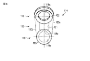
図5から図8は、他の実施形態による釣り糸ガイド110を示す。なお、以下に説明する実施形態も基本的には上述の実施形態と同様であるため、同様な部位には100番台の同様な符号を付し、詳細な説明を省略する。
5 to 8 show a
図5および図6に示すように、この実施形態のフレーム114は、釣り糸案内部116を固定部118よりも大径に形成してあり、連結部120の側縁部120a,120bは上方に向けて幅が拡大する直線状に形成してある。
As shown in FIGS. 5 and 6, the
釣り糸案内部116の突部124がフレーム114の前側側面から突出する突出量d1は、固定部118の突部126の突出量d2よりも大きく形成してあり、フレーム114の後側の側面から前端まで、軸方向に沿って滑らかにカールした曲面状の広い釣り糸案内面122を形成する。また、突部124の外径は、符号rで示すように釣り糸案内部116の頂部の外径よりも小さく形成してあり、フレーム114との間に微小凹部125を形成する。このような突部124により、糸ガカリを確実に防止することのできる案内面122の加工性を向上することができる。
The protrusion amount d1 of the
また、固定部118の突部126は、フレーム114から前方に突出する筒状構造を有しており、例えばバーリング加工により形成することができる。固定部118を軸方向に長い筒状構造に形成することにより、筒状体112上に安定した状態で保持することができる。装着孔118aの後端部には、後方に向けて拡径する曲面状の案内面118cを形成してあり、筒状体112の小径部134を装着孔118a内に滑らかに案内することができる。
Further, the
図7に示すように、筒状体112は、大径部130が球面状部130aと円筒状部130bとの間に、円錐状部130cを配置してあり、この円錐状部は、球面状部130aから拡径しつつ円筒状部130まで滑らかに連続する円錐状面を形成する。このため、円筒状部130bの軸方向寸法は球面状部130aよりも短く形成してある。本実施形態では、円錐状部130cが大径部130上で最も大きな領域を占めている。
As shown in FIG. 7, in the
受け部132は、フレーム114の固定部118とほぼ等しい軸方向寸法を有し、回り止め突起136を、固定部118の回り止め凹部118bに嵌合することで、筒状体112とフレーム114との相対回転を確実に防止する。
The receiving
また、小径部134は、前端に形成したテーパ面134aと、後端に形成した厚肉部134bとを有する。この厚肉部134bは受け部132よりも僅かに大径に拡径した円筒状面を有し、回り止め突起136の外端面に連続する。厚肉部134bは、固定部118の突起126の前端面に当接し、フレーム114の抜け止めとして作用する。
Moreover, the
この小径部134の前端部は、大径部130の球状面部130aよりも大径に形成してあり、軸線Cに対して垂直な環状端面135を形成する。
The front end portion of the
この筒状体112にフレーム114を装着する場合も、図7に示すように、筒状体112の内孔112aと固定部118の装着孔118aを軸方向に整合させ、前方の小径部134から挿通する。テーパ面134aが装着孔118aの案内面118cで案内される。フレーム114の回り止め凹部118bと受け部132に形成した回り止め突起136とを互いに軸方向に整合させた状態で、固定部118を小径部134上に圧入し、この小径部134の厚肉部134bを越えて受け部132上に押し込み、固定部118の後側の側面を大径部130の前端面138に当接させる。
Even when the
これにより、フレーム114は、小径部134で筒状体112上に抜け止めされた状態で保持され、糸ガラミを確実に防止することのできる釣り糸ガイド110を容易に製造することができる。この小径部134は、フレーム114の抜け止めとして作用することに加え、球状面部130a大きな外径を有して受け部132から前方に突出することで、この筒状体112の強度を向上し、釣り竿の竿杆8に装着した際に安定した状態で保持することができる。
As a result, the
前記フレーム14,114に炭素ドープ酸化チタン層を形成するとよい。これにより、フレーム自体の表面硬度を高くでき、耐磨耗性を向上できる。また、フレーム14,114自体に層を形成できるので、メッキ等のように剥離が発生することもない。
A carbon-doped titanium oxide layer may be formed on the
なお、本発明は、上述の実施形態に限るものではなく、これらの実施形態を様々に組合せあるいは変形することが可能である。例えばフレーム14に筒状体112を組合せ、あるいは、フレーム114に筒状体12を組み合わせることも可能である。
以下に、本願出願の当初の特許請求の範囲に記載された発明を付記する。
[1] 金属製フレームに釣糸案内部と固定部とを形成し、この固定部を筒状体の受け部に装着した釣り糸ガイドであって、
前記フレームの釣り糸案内部は固定部に対して軸方向の前方に傾斜し、
前記筒状体は、前記受け部の軸方向前側に配置された前筒部と軸方向後側に配置された後筒部とを有し、
前記後筒部は、軸方向に沿う竿杆挿入孔の後端周縁部から前方に向かって湾曲する湾曲面状の外周面を有することを特徴とする釣り糸ガイド。
[2] 金属製フレームに釣糸案内部と固定部とを形成し、この固定部を筒状体の受け部に装着した釣り糸ガイドであって、
前記フレームの釣り糸案内部は固定部に対して軸方向の前方に傾斜し、
前記筒状体は、前記受け部の軸方向前側に配置された前筒部と軸方向後側に配置された後筒部とを有し、
前記後筒部は、軸方向に沿う竿杆挿入孔の後端周縁部から前方に向かって順に拡径する外周面を有し、
前記前筒部は、拡径した厚肉部を有することを特徴とする釣り糸ガイド。
[3] 前記フレームは、釣り糸案内部と固定部との間に配置される連結部を有し、前記固定部は、この連結部の側縁部に連続し、かつ前記後筒部よりも2mm以内の範囲でこの後筒部から外方に突出する外側部を有し、この外側部を前記釣り糸案内部と同程度の平滑面に形成したことを特徴とする[1]又は[2]に記載の釣り糸ガイド。
[4] 前記後筒部は、前筒部よりも2倍以上の軸方向長さを有することを特徴とする[1]から[3]のいずれか1に記載の釣り糸ガイド。
[5] 前記フレームの釣り糸案内部と固定部とは、それぞれ前方に突出する突部を有し、前記固定部の突部が突出する長さは、釣り糸案内部の突部よりも短くかつフレームの肉厚以下であることを特徴とする[1]から[4]のいずれか1に記載の釣り糸ガイド。
In addition, this invention is not restricted to the above-mentioned embodiment, These embodiments can be combined or modified in various ways. For example, the
Hereinafter, the invention described in the scope of claims of the present application will be appended.
[1] A fishing line guide in which a fishing line guide portion and a fixing portion are formed on a metal frame, and the fixing portion is attached to a receiving portion of a cylindrical body,
The fishing line guide part of the frame is inclined forward in the axial direction with respect to the fixed part,
The cylindrical body has a front cylindrical portion disposed on the front side in the axial direction of the receiving portion and a rear cylindrical portion disposed on the rear side in the axial direction.
The fishing line guide characterized in that the rear tube portion has a curved outer peripheral surface that curves forward from a rear end peripheral portion of the rod insertion hole along the axial direction.
[2] A fishing line guide in which a fishing line guide portion and a fixing portion are formed on a metal frame, and the fixing portion is attached to a receiving portion of a cylindrical body,
The fishing line guide part of the frame is inclined forward in the axial direction with respect to the fixed part,
The cylindrical body has a front cylindrical portion disposed on the front side in the axial direction of the receiving portion and a rear cylindrical portion disposed on the rear side in the axial direction.
The rear cylinder portion has an outer peripheral surface that gradually increases in diameter from the rear end peripheral portion of the flange insertion hole along the axial direction toward the front,
The fishing line guide characterized in that the front cylinder part has a thick part with an enlarged diameter.
[3] The frame includes a connecting portion disposed between the fishing line guide portion and the fixing portion, and the fixing portion is continuous with a side edge portion of the connecting portion and is 2 mm from the rear tube portion. [1] or [2], characterized in that it has an outer part protruding outward from the rear cylinder part within a range of within, and this outer part is formed on a smooth surface comparable to the fishing line guide part. The described fishing line guide.
[4] The fishing line guide according to any one of [1] to [3], wherein the rear tube portion has an axial length twice or more that of the front tube portion.
[5] The fishing line guide portion and the fixing portion of the frame each have a protrusion protruding forward, and the length of the protrusion of the fixing portion protruding is shorter than the protrusion of the fishing line guide portion and the frame. The fishing line guide according to any one of [1] to [4], wherein the fishing line guide has a thickness equal to or less than the thickness of the fishing line.
10,110…釣り糸ガイド、12,112…筒状体、14,114…フレーム、16,116…釣り糸案内部、18,118…固定部、30,130…大径部(後筒部)、32,132…受け部、34,134…小径部(前筒部)。 DESCRIPTION OF SYMBOLS 10,110 ... Fishing line guide, 12, 112 ... Cylindrical body, 14, 114 ... Frame, 16, 116 ... Fishing line guide part, 18, 118 ... Fixed part, 30, 130 ... Large diameter part (rear cylinder part), 32 132, receiving part, 34, 134, small diameter part (front cylinder part).
Claims (4)
前記フレームは、前記釣り糸案内部と前記固定部との間に配置される連結部を有し、この連結部は、前記固定部との間に段部を形成することなく滑らかに湾曲しつつ前記釣り糸案内部に連続し、
前記フレームの前記釣り糸案内部は前記固定部に対して軸方向の前方に傾斜し、
前記筒状体は、前記受け部の軸方向前側に配置された小径部と軸方向後側に配置された大径部とを有し、
前記大径部は、軸方向に沿う竿杆挿入孔の後端周縁部から前方に向かって湾曲する湾曲面状の外周面を有し、
前記フレームの前記固定部は、前記連結部の側縁部に連続し、かつ前記大径部よりも2mm以内の範囲でこの大径部から外方に突出する外側部を有し、この外側部を前記釣り糸案内部と同程度の平滑面に形成することを特徴とする釣り糸ガイド。 Frame to form a fixing portion fishing Ri thread guide portion, the fixed portion is attached to the receiving portion of the cylindrical body, moving back and forth a rod杆上from the tip side of the front of the fishing rod along the original side of the rear A fishing line guide held on the outer periphery of the rod,
Wherein the frame has a connecting portion disposed between the fishing line guide portion and the fixed portion, the connecting portion, while smoothly curved without forming a step portion between the fixing portion Continue to the fishing line guide,
The fishing line guide portion of the frame is inclined forward in the axial direction with respect to the fixed portion,
The cylindrical body has a small-diameter portion disposed on the front side in the axial direction of the receiving portion and a large-diameter portion disposed on the rear side in the axial direction.
The large diameter portion, have a curved surface shaped outer peripheral surface of which is curved toward the front from the rear end periphery of the rod rod insertion hole along the axial direction,
The fixing portion of the frame has an outer portion that is continuous with a side edge portion of the connecting portion and protrudes outward from the large diameter portion within a range of 2 mm from the large diameter portion. Is formed on a smooth surface comparable to the fishing line guide portion .
前記フレームは、前記釣り糸案内部と前記固定部との間に配置される連結部を有し、この連結部は、前記固定部との間に段部を形成することなく滑らかに湾曲しつつ前記釣り糸案内部に連続し、
前記フレームの前記釣り糸案内部は前記固定部に対して軸方向の前方に傾斜し、
前記筒状体は、前記受け部の軸方向前側に配置された小径部と軸方向後側に配置された大径部とを有し、
前記大径部は、軸方向に沿う竿杆挿入孔の後端周縁部から前方に向かって順に拡径する外周面を有し、前記小径部は、拡径した厚肉部を有し、
前記フレームの前記固定部は、前記連結部の側縁部に連続し、かつ前記大径部よりも2mm以内の範囲でこの大径部から外方に突出する外側部を有し、この外側部を前記釣り糸案内部と同程度の平滑面に形成することを特徴とする釣り糸ガイド。 Frame to form a fixing portion fishing Ri thread guide portion, the fixed portion is attached to the receiving portion of the cylindrical body, moving back and forth a rod杆上from the tip side of the front of the fishing rod along the original side of the rear A fishing line guide held on the outer periphery of the rod,
Wherein the frame has a connecting portion disposed between the fishing line guide portion and the fixed portion, the connecting portion, while smoothly curved without forming a step portion between the fixing portion Continue to the fishing line guide,
The fishing line guide portion of the frame is inclined forward in the axial direction with respect to the fixed portion,
The cylindrical body has a small-diameter portion disposed on the front side in the axial direction of the receiving portion and a large-diameter portion disposed on the rear side in the axial direction.
Said large diameter portion has an outer peripheral surface that sequentially increases in diameter toward the front from the rear end periphery of the rod rod insertion hole along the axial direction, the small diameter portion, have a diameter the thick portions,
The fixing portion of the frame has an outer portion that is continuous with a side edge portion of the connecting portion and protrudes outward from the large diameter portion within a range of 2 mm from the large diameter portion. Is formed on a smooth surface comparable to the fishing line guide portion .
Priority Applications (1)
| Application Number | Priority Date | Filing Date | Title |
|---|---|---|---|
| JP2008312466A JP5601769B2 (en) | 2008-12-08 | 2008-12-08 | Fishing line guide |
Applications Claiming Priority (1)
| Application Number | Priority Date | Filing Date | Title |
|---|---|---|---|
| JP2008312466A JP5601769B2 (en) | 2008-12-08 | 2008-12-08 | Fishing line guide |
Publications (3)
| Publication Number | Publication Date |
|---|---|
| JP2010130988A JP2010130988A (en) | 2010-06-17 |
| JP2010130988A5 JP2010130988A5 (en) | 2012-01-26 |
| JP5601769B2 true JP5601769B2 (en) | 2014-10-08 |
Family
ID=42342980
Family Applications (1)
| Application Number | Title | Priority Date | Filing Date |
|---|---|---|---|
| JP2008312466A Active JP5601769B2 (en) | 2008-12-08 | 2008-12-08 | Fishing line guide |
Country Status (1)
| Country | Link |
|---|---|
| JP (1) | JP5601769B2 (en) |
Families Citing this family (5)
| Publication number | Priority date | Publication date | Assignee | Title |
|---|---|---|---|---|
| JP5393627B2 (en) * | 2010-04-19 | 2014-01-22 | グローブライド株式会社 | Fishing line guide |
| JP5606858B2 (en) * | 2010-09-30 | 2014-10-15 | グローブライド株式会社 | Fishing line guide |
| JP5838127B2 (en) * | 2012-05-30 | 2015-12-24 | グローブライド株式会社 | Fishing line guide |
| JP2015047079A (en) * | 2013-08-30 | 2015-03-16 | グローブライド株式会社 | Fishing line guide and fishing rod |
| JP6906938B2 (en) * | 2016-12-13 | 2021-07-21 | 株式会社シマノ | Floating guide for swing rod and swing rod |
Family Cites Families (4)
| Publication number | Priority date | Publication date | Assignee | Title |
|---|---|---|---|---|
| JPS53150792U (en) * | 1977-05-06 | 1978-11-28 | ||
| JPS53162096U (en) * | 1977-05-27 | 1978-12-19 | ||
| JPS5649344Y2 (en) * | 1978-10-13 | 1981-11-17 | ||
| JP4275457B2 (en) * | 2003-05-16 | 2009-06-10 | 富士工業株式会社 | Fishing rod guide |
-
2008
- 2008-12-08 JP JP2008312466A patent/JP5601769B2/en active Active
Also Published As
| Publication number | Publication date |
|---|---|
| JP2010130988A (en) | 2010-06-17 |
Similar Documents
| Publication | Publication Date | Title |
|---|---|---|
| JP5601769B2 (en) | Fishing line guide | |
| JP5555419B2 (en) | Fishing line guide | |
| CA2524768C (en) | Reinforcing ring for a plastic fitting and plastic fitting incorporating a reinforcing ring | |
| TWI804710B (en) | Guide frame of fishing line guiding device, fishing line guiding device and fishing rod | |
| JP2017046644A (en) | Fishing line guide, fishing rod, guide frame, and guide frame manufacturing method | |
| JP2004337105A (en) | Guide for fishing rod | |
| JP6805029B2 (en) | Fishing rod and tip rod body of fishing rod | |
| JP6443975B2 (en) | Fishing line guide, fishing rod and guide frame | |
| JP2007006767A (en) | Fishing rod | |
| JP6553456B2 (en) | Fishing line guide, fishing rod and guide ring | |
| JP6247587B2 (en) | Fishing line guide and swing rod for swing rod | |
| JP2017029074A (en) | Top guide, fishing rod, and guide frame | |
| JP6723851B2 (en) | Top guides for draw-out rods, draw-out rods and guide frames | |
| WO2019142622A1 (en) | Fishing line guide and fishing rod equipped with same | |
| JP2019097540A (en) | Top guide and fishing rod, and guide frame | |
| JP2016015950A (en) | Fishing line guide and fishing rod as well as guide ring | |
| JP7372855B2 (en) | Soft member mounting structure | |
| JP2021133673A (en) | Mounting structure of soft member | |
| JP7169932B2 (en) | Guide frame for fishing line guide, fishing line guide and fishing rod | |
| JP5662716B2 (en) | Reel seat and bat | |
| JP2007259740A (en) | Fishing rod | |
| JP2023144589A (en) | Fish line guide and fish rod | |
| KR20210108870A (en) | Fixing supporter and fishing rod | |
| JP2023008795A (en) | Guide frame for fishing line guide, fishing line guide, and fishing rod | |
| JP2023156221A (en) | Guide frame of fishing thread guide, fishing thread guide, and fishing rod |
Legal Events
| Date | Code | Title | Description |
|---|---|---|---|
| A621 | Written request for application examination |
Free format text: JAPANESE INTERMEDIATE CODE: A621 Effective date: 20111102 |
|
| A521 | Request for written amendment filed |
Free format text: JAPANESE INTERMEDIATE CODE: A523 Effective date: 20111201 |
|
| A977 | Report on retrieval |
Free format text: JAPANESE INTERMEDIATE CODE: A971007 Effective date: 20121116 |
|
| A131 | Notification of reasons for refusal |
Free format text: JAPANESE INTERMEDIATE CODE: A131 Effective date: 20121120 |
|
| A521 | Request for written amendment filed |
Free format text: JAPANESE INTERMEDIATE CODE: A523 Effective date: 20130118 |
|
| A131 | Notification of reasons for refusal |
Free format text: JAPANESE INTERMEDIATE CODE: A131 Effective date: 20130924 |
|
| A02 | Decision of refusal |
Free format text: JAPANESE INTERMEDIATE CODE: A02 Effective date: 20140507 |
|
| A521 | Request for written amendment filed |
Free format text: JAPANESE INTERMEDIATE CODE: A523 Effective date: 20140611 |
|
| A911 | Transfer to examiner for re-examination before appeal (zenchi) |
Free format text: JAPANESE INTERMEDIATE CODE: A911 Effective date: 20140707 |
|
| TRDD | Decision of grant or rejection written | ||
| A01 | Written decision to grant a patent or to grant a registration (utility model) |
Free format text: JAPANESE INTERMEDIATE CODE: A01 Effective date: 20140722 |
|
| A61 | First payment of annual fees (during grant procedure) |
Free format text: JAPANESE INTERMEDIATE CODE: A61 Effective date: 20140819 |
|
| R150 | Certificate of patent or registration of utility model |
Ref document number: 5601769 Country of ref document: JP Free format text: JAPANESE INTERMEDIATE CODE: R150 |
|
| R250 | Receipt of annual fees |
Free format text: JAPANESE INTERMEDIATE CODE: R250 |
|
| R250 | Receipt of annual fees |
Free format text: JAPANESE INTERMEDIATE CODE: R250 |
|
| R250 | Receipt of annual fees |
Free format text: JAPANESE INTERMEDIATE CODE: R250 |
|
| R250 | Receipt of annual fees |
Free format text: JAPANESE INTERMEDIATE CODE: R250 |
|
| R250 | Receipt of annual fees |
Free format text: JAPANESE INTERMEDIATE CODE: R250 |
|
| R250 | Receipt of annual fees |
Free format text: JAPANESE INTERMEDIATE CODE: R250 |
|
| R250 | Receipt of annual fees |
Free format text: JAPANESE INTERMEDIATE CODE: R250 |